

Page 1

Translation of the original manual
Assembly and Operating Manual
PGM 29 - 140
2-Finger Parallel Gripper
Page 2

Imprint
2
04.00 | PGM 29 - 140 | Assembly and Operating Manual | en | 389284
Imprint
Copyright:
This manual is protected by copyright. The author is SCHUNK GmbH & Co. KG. All rights
reserved. Any reproduction, processing, distribution (making available to third parties),
translation or other usage - even excerpts - of the manual is especially prohibited and
requires our written approval.
Technical changes:
We reserve the right to make alterations for the purpose of technical improvement.
Document number: 389284
Version: 04.00|05/02/2019|en
© SCHUNK GmbH & Co. KG
All rights reserved.
Dear Customer,
thank you for trusting our products and our family-owned company, the leading
technology supplier of robots and production machines.
Our team is always available to answer any questions on this product and other solutions.
Ask us questions and challenge us. We will find a solution!
Best regards,
Your SCHUNK team
SCHUNK GmbH & Co. KG
Spann- und Greiftechnik
Bahnhofstr. 106 – 134
D-74348 Lauffen/Neckar
Tel. +49-7133-103-0
Fax +49-7133-103-2399
[email protected]
schunk.com
Page 3

Table of contents
04.00 | PGM 29 - 140 | Assembly and Operating Manual | en | 389284
3
Table of contents
1 General.................................................................................................................... 4
1.1 About this manual ................................................................................................4
1.1.1 Presentation of Warning Labels ...............................................................4
1.1.2 Applicable documents ..............................................................................5
1.2 Warranty .............................................................................................................. 5
1.3 Scope of delivery ..................................................................................................5
1.3.1 Accessories pack.......................................................................................5
1.4 Accessories ........................................................................................................... 5
2 Basic safety notes ................................................................................................... 6
2.1 Intended use......................................................................................................... 6
2.2 Not intended use.................................................................................................. 6
2.3 Environmental and operating conditions .............................................................6
2.4 Product safety ...................................................................................................... 7
2.5 Personnel qualification......................................................................................... 7
2.6 Using personal protective equipment ..................................................................8
2.7 Notes on particular risks....................................................................................... 8
3 Technical data.........................................................................................................10
4 Assembly ................................................................................................................11
4.1 Mechanical connection ...................................................................................... 11
4.2 Air connection .................................................................................................... 12
4.3 Mounting the sensor .......................................................................................... 13
4.3.1 Proximity switch IN 40 / 80.....................................................................13
4.3.2 Programmable magnetic switch (MMS-P)..............................................16
5 Troubleshooting .....................................................................................................21
5.1 Product is not moving......................................................................................... 21
5.2 The module does not travel through the entire stroke? .................................... 21
5.3 Product opens or closes abruptly ....................................................................... 21
5.4 Gripping force is dropping.................................................................................. 22
5.5 Product does not achieve the opening and closing times.................................. 22
6 Maintenance ..........................................................................................................23
6.1 Notes ..................................................................................................................23
6.2 Maintenance and lubrication intervals............................................................... 23
6.3 Lubricants/Lubrication points (basic lubrication) ..............................................23
6.4 Servicing the module.......................................................................................... 23
7 Translation of original declaration of incorporation ................................................24
8 Annex to Declaration of Incorporation....................................................................25
Page 4
General
4
04.00 | PGM 29 - 140 | Assembly and Operating Manual | en | 389284
1 General
1.1 About this manual
This manual contains important information for a safe and
appropriate use of the product.
This manual is an integral part of the product and must be kept
accessible for the personnel at all times.
Before starting work, the personnel must have read and
understood this operating manual. Prerequisite for safe working is
the observance of all safety instructions in this manual.
Illustrations in this manual are provided for basic understanding
and may differ from the actual product design.
In addition to these instructions, the documents listed under
Applicable documents [}5] are applicable.
1.1.1 Presentation of Warning Labels
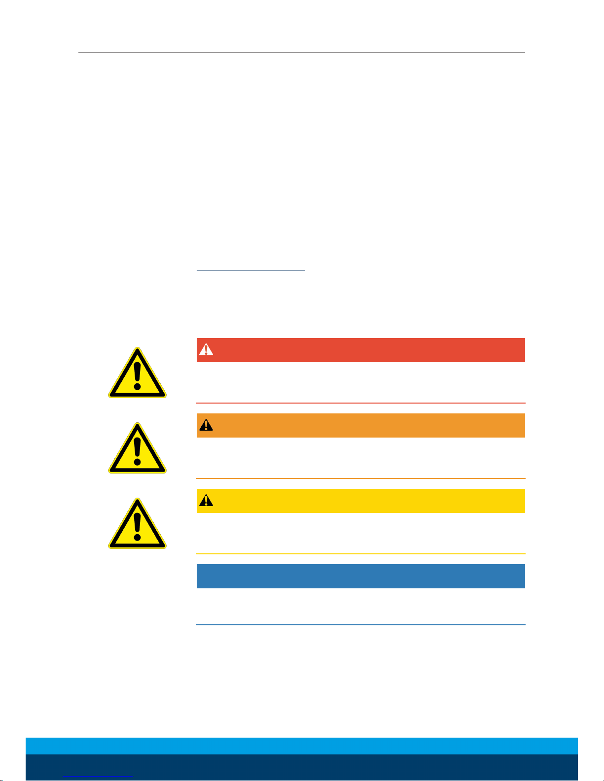
To make risks clear, the following signal words and symbols are
used for safety notes.
DANGER
Danger for persons!
Non-observance will inevitably cause irreversible injury or death.
WARNING
Dangers for persons!
Non-observance can lead to irreversible injury and even death.
CAUTION
Dangers for persons!
Non-observance can cause minor injuries.
NOTICE
Material damage!
Information about avoiding material damage.
Page 5
General
04.00 | PGM 29 - 140 | Assembly and Operating Manual | en | 389284
5
1.1.2 Applicable documents
• General terms of business*
• Catalog data sheet of the purchased product *
• Assembly and operating manuals of the accessories *
The documents marked with an asterisk (*) can be downloaded on
our homepage schunk.com
1.2 Warranty
If the product is used as intended, the warranty is valid for 24
months from the ex-works delivery date under the following
conditions:
• Observe the specified maintenance and lubrication intervals
• Observe the ambient conditions and operating conditions
Parts touching the workpiece and wear parts are not included in
the warranty.
1.3 Scope of delivery
The scope of delivery includes
• 2-Finger Parallel Gripper PGM in the version ordered
• Assembly and Operating Manual
• Accessory pack
1.3.1 Accessories pack
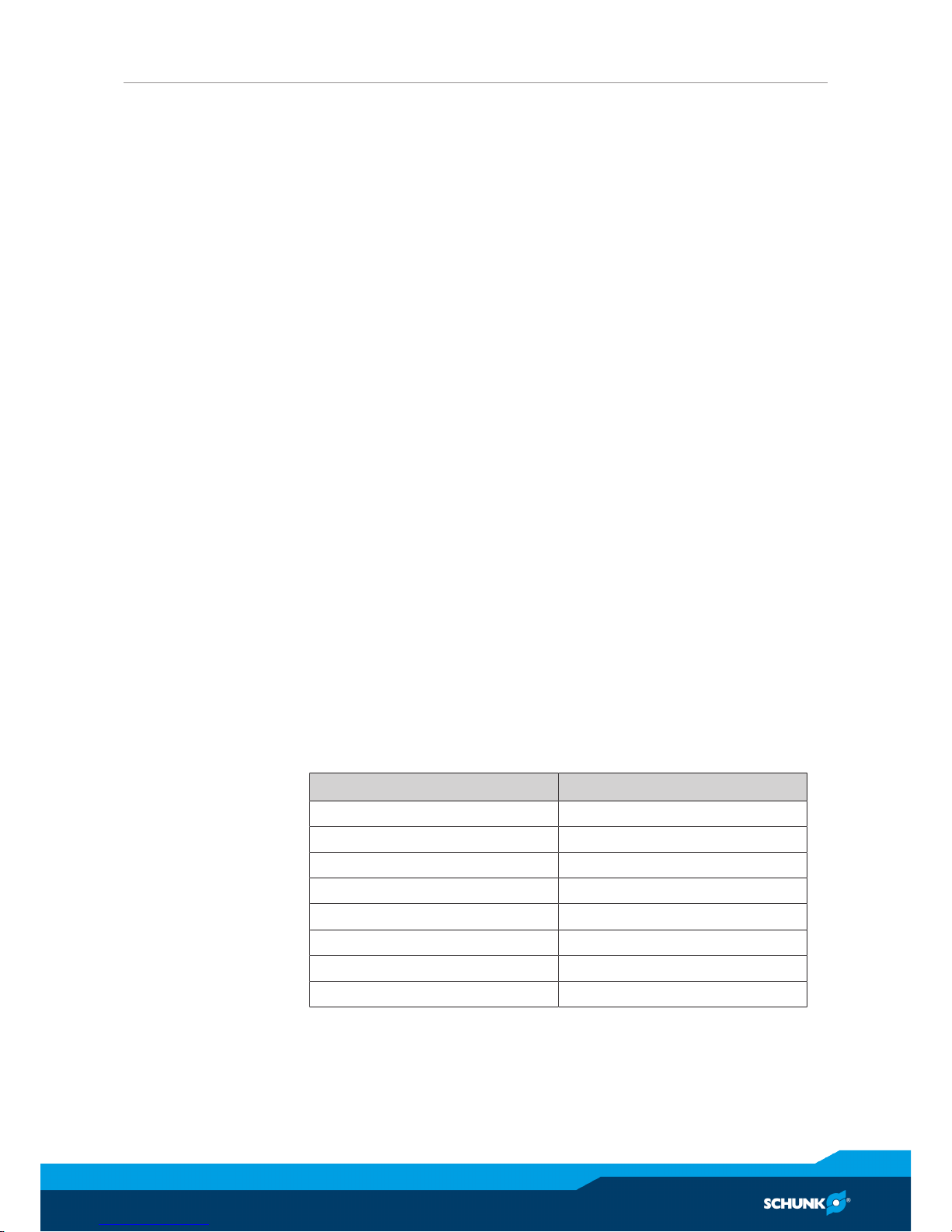
Content of the accessory pack:
• 6 x Centering sleeves for mounting
ID.-No. of the accessory pack
Accessory pack for ID number
PGM 29 5516094
PGM 38 5516095
PGM 50 5516096
PGM 60 5516097
PGM 82 5516098
PGM 96 5516099
PGM 120 5516100
PGM 140 5516101
1.4 Accessories
A wide range of accessories are available for this product
For information regarding which accessory articles can be used
with the corresponding product variants, see catalog data sheet.
Page 6

Basic safety notes
6
04.00 | PGM 29 - 140 | Assembly and Operating Manual | en | 389284
2 Basic safety notes
2.1 Intended use
The product is designed exclusively for gripping and temporarily
holding workpieces or objects.
• The product may only be used within the scope of its technical
data, Technical data [}10].
• When implementing and operating components in safetyrelated parts of the control systems, the basic safety principles
in accordance with DIN EN ISO 13849-2 apply. The proven safety
principles in accordance with DIN EN ISO 13849-2 also apply to
categories 1, 2, 3 and 4.
• The product is intended for installation in a machine/system.
The applicable guidelines must be observed and complied with.
• The product is intended for industrial and industry-oriented use.
• Appropriate use of the product includes compliance with all
instructions in this manual.
2.2 Not intended use
It is not intended use if the product is used, for example, as a
pressing tool, stamping tool, lifting gear, guide for tools, cutting
tool, clamping device or a drilling tool.
• Any utilization that exceeds or differs from the appropriate use
is regarded as misuse.
2.3 Environmental and operating conditions
Required ambient conditions and operating conditions
Incorrect ambient and operating conditions can make the product
unsafe, leading to the risk of serious injuries, considerable material
damage and/or a significant reduction to the product's life span.
See also Environmental and operating conditions [}6].
• Make sure that the product and the top jaws are a sufficient
size for the application.
• Ensure that maintenance and lubrication intervals are observed,
Maintenance [}23].
Page 7

Basic safety notes
04.00 | PGM 29 - 140 | Assembly and Operating Manual | en | 389284
7
2.4 Product safety
Dangers arise from the product, if:
• the product is not used in accordance with its intended
purpose.
• the product is not installed or maintained properly.
• the safety and installation notes are not observed.
Avoid any manner of working that may interfere with the function
and operational safety of the product.
Wear protective equipment.
NOTE
More information is contained in the relevant chapters.
2.5 Personnel qualification
Inadequate qualifications of the personnel
If the personnel working with the product is not sufficiently
qualified, the result may be serious injuries and significant
property damage.
• All work may only be performed by qualified personnel.
• Before working with the product, the personnel must have read
and understood the complete assembly and operating manual.
• Observe the national safety regulations and rules and general
safety instructions.
The following personal qualifications are necessary for the various
activities related to the product:
Trained electrician
Due to their technical training, knowledge and experience, trained
electricians are able to work on electrical systems, recognize and
avoid possible dangers and know the relevant standards and
regulations.
Qualified personnel
Due to its technical training, knowledge and experience, qualified
personnel is able to perform the delegated tasks, recognize and
avoid possible dangers and knows the relevant standards and
regulations.
Instructed person
Instructed persons were instructed by the operator about the
delegated tasks and possible dangers due to improper behaviour.
Service personnel of
the manufacturer
Due to its technical training, knowledge and experience, service
personnel of the manufacturer is able to perform the delegated
tasks and to recognize and avoid possible dangers.
Page 8

Basic safety notes
8
04.00 | PGM 29 - 140 | Assembly and Operating Manual | en | 389284
2.6 Using personal protective equipment
When using this product, observe the relevant industrial safety
regulations and use the personal protective equipment (PPE)
required!
• Use protective gloves, safety shoes and safety goggles..
• Observe safe distances.
2.7 Notes on particular risks
Generally valid:
• Remove the energy supplies before installation, modification,
maintenance, or adjustment work.
• Make sure that no residual energy remains in the system.
• Do not move parts by hand when the energy supply is
connected.
• Do not reach into the open mechanism or the movement area
of the module.
• Perform maintenance, modifications, and additions outside of
the danger zone.
• For all work, secure the unit against accidental operation.
• Take a precautionary approach by maintenance and
disassembly.
• Only specially trained staff should disassemble the module.
Page 9
Basic safety notes
04.00 | PGM 29 - 140 | Assembly and Operating Manual | en | 389284
9
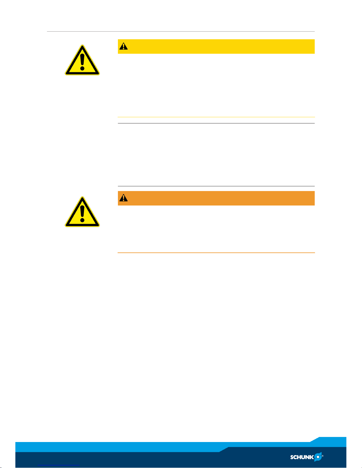
CAUTION
Possible risk of injury due to electrostatic energy!
Components or assembly groups may become electrostatically
charged. When touched, the electrostatic discharge can trigger a
startle response, which can result in injuries.
• The operator must ensure that all components and assembly
groups are included in the local equipotential bonding in line
with the applicable regulations.
NOTE
• The equipotential bonding must be installed by a specialist
electrician in line with the applicable regulations, paying
particular attention to the actual conditions in the working
environment.
• The effectiveness of the equipotential bonding must be verified
by a specialist electrician through regular safety measurements.
WARNING
Risk of injury from objects falling and being ejected!
Falling and ejected objects during operation can lead to serious
injury or death.
• Take appropriate protective measures to secure the danger
zone.
Page 10

Technical data
10
04.00 | PGM 29 - 140 | Assembly and Operating Manual | en | 389284
3 Technical data
Size 29 38 50 60 82 96 120 140
Weight [kg] 0.025 0.050 0.105 0.210 0.60 0.84 1.26 2.55
Max. permissible finger length [mm] 15 25 40 50 65 80 110 140
Max. permitted weight per top jaw
[kg]
0.010 0.017 0.035 0.070 0.17 0.28 0.58 1.0
Min. ambient temperature [°C] - 10
Max. ambient temperature [°C] + 90
Stroke per jaw [mm] 2 3 4 5 10 12 12 15
Closing force [N] 30 47 75 190 320 540 760 1180
Opening force [N] 40 63 95 210 350 580 810 1250
IP rating 30
Noise emission [dB(A)] ≤ 70
Pressure medium Compressed air, compressed air quality according
to ISO 8573-1:7 4 4
Min. pressure [bar] 2
Max. pressure [bar] 8
Nominal working pressure [bar] 6
More technical data is included in the catalog data sheet.
Whichever is the latest version.
Page 11
Assembly
04.00 | PGM 29 - 140 | Assembly and Operating Manual | en | 389284
11
4 Assembly
4.1 Mechanical connection
Evenness of the
mounting surface
The values apply to the whole mounting surface to which the
product is mounted.
Requirements for evenness of the mounting surface (Dimensions in mm)
Edge length Permissible unevenness
< 100 < 0.02
> 100 < 0.05
Mounting
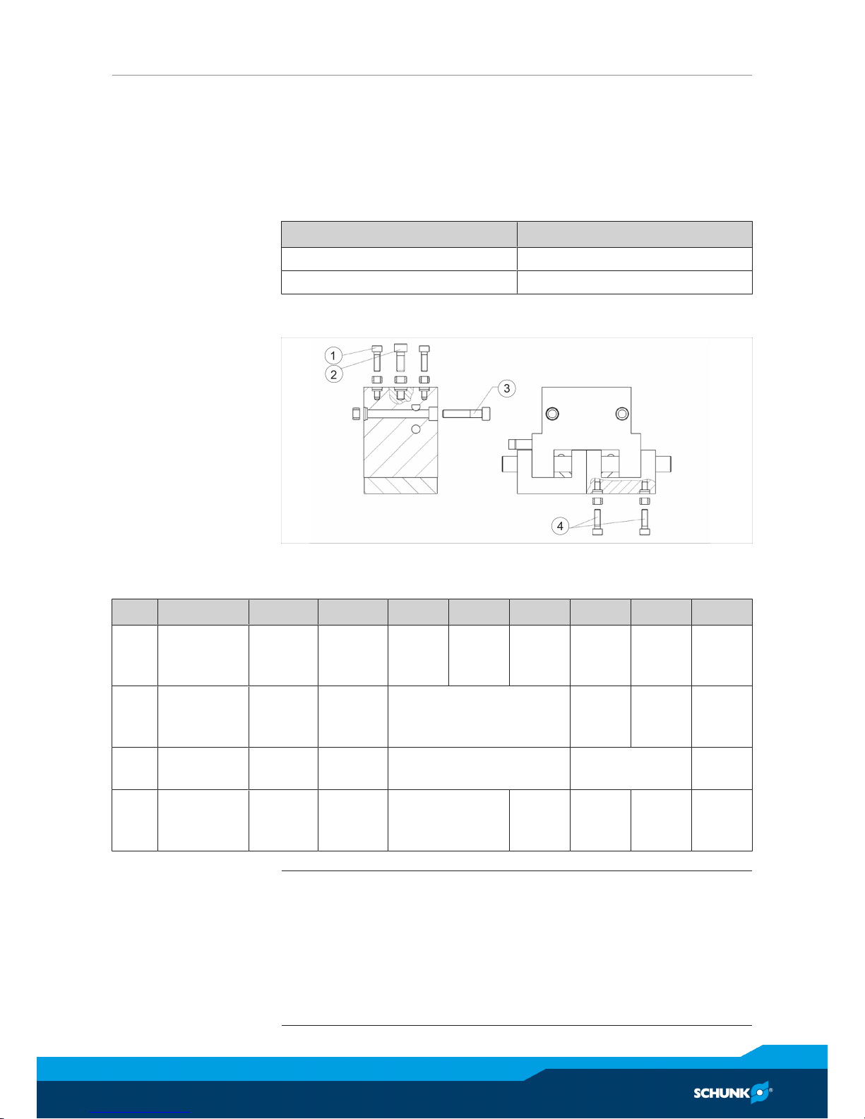
The module can be mounted from the side and rear.
Assembly options
Mounting material (provided by customer)
Item Mounting 29 38 50 60 82 96 120 140
1 Rear
module
M3
4.5 deep
- - - - - - M6
10
deep
2 Rear
module
M2.5
4.5 deepM37 deep
M4
10 deep
M6
10
deep
M6
11
deep
M8
12
deep
3 Module on
the side
- M2.5 M4 M6 M8
4 Top jaws M3
4 deepM37.5 deep
M4
8 deep
M4
10
deep
M6
10
deep
M4
11
deep
M4
12
deep
NOTE
• The centering sleeves needed for centering are supplied in the
accessory pack.
• For mounting from the rear or side fix the module on the
proposed fixing bores with centering sleeves.
• Mount the module using the mounting bores.
• Mount the top jaws using the mounting bores.
Page 12
Assembly
12
04.00 | PGM 29 - 140 | Assembly and Operating Manual | en | 389284
4.2 Air connection
NOTICE
Damage to the gripper is possible!
If the maximum permissible finger weight or the permissible
mass moment of inertia of the fingers is exceeded, the gripper
can be damaged.
• A jaw movement always has to be without jerks and bounce.
• You must therefore implement sufficient reduction and/or
damping.
• Observe the diagrams and information in the catalog data
sheet.
NOTE
• Observe the requirements for the compressed air supply,
Technical data [}10].
• In case of compressed air loss (cutting off the energy line), the
components lose their dynamic effects and do not remain in a
secure position. However, the use of a SDV-P pressure
maintenance valve is recommended in this case in order to
maintain the dynamic effect for some time. Product variants
are also offered with mechanical gripping force via springs,
which also ensure a minimum clamping force in the event of a
pressure drop.
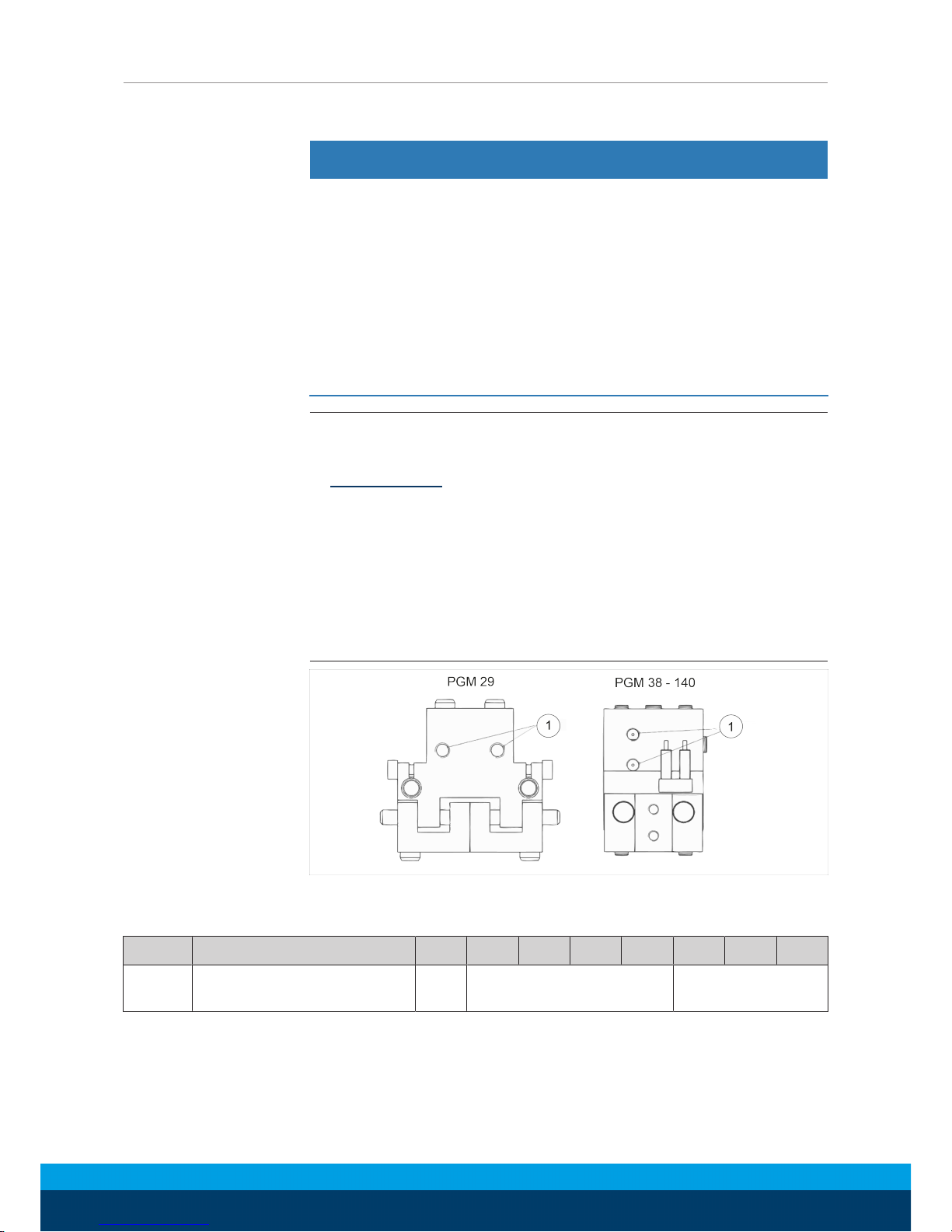
Luftanschlüsse
Thread diameter of the air connections
Item Connection 26 38 50 60 82 96 120 140
1 Hose connection
(A = AUF, B = ZU)
M3 M5 G 1/8"
• Open only the air connections that are needed.
• Close unused main air connections using the screw plugs from
the enclosed pack.
• For a hose-free direction connection, use the O-rings from the
enclosed pack.
Page 13
Assembly
04.00 | PGM 29 - 140 | Assembly and Operating Manual | en | 389284
13
4.3 Mounting the sensor
NOTE
Observe the assembly and operating manual of the sensor for
mounting and connecting.
The product is prepared for the use of sensors.
• For the exact type designations of suitable sensors, please see
catalog datasheet and Link Übersicht Sensoren.
• For technical data for the suitable sensors, see assembly and
operating manual and catalog datasheet.
– The assembly and operating manual and catalog datasheet
are included in the scope of delivery for the sensors and are
available at schunk.com.
• Information on handling sensors is available at schunk.com or
from SCHUNK contact persons.
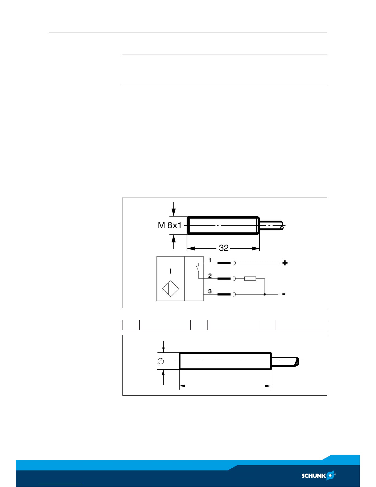
4.3.1 Proximity switch IN 40 / 80
Connection example for IN 80
1 brown 2 black 3 blue
4
25
Page 14
Assembly
14
04.00 | PGM 29 - 140 | Assembly and Operating Manual | en | 389284
brown
black
blue
load
closer
Types that can be ordered (☞ catalog):
The inductive proximity switches used are equipped with reverse
polarity protection and are short-circuit-proof.
Make sure that you handle the proximity switches properly:
• Do not pull on the cable.
• Do not allow the sensor to dangle from the cable.
• Do not overtighten the mounting screw or mounting clip.
• Please adhere to a permitted bend radius of the cable (☞
catalog).
• Avoid contact of the proximity switches with hard objects and
with chemicals, in particular nitric acid, chromic acid and
sulphuric acid.
The inductive proximity switches are electronic components,
which can react sensitively to high-frequency interference or
electromagnetic fields.
• Check to make sure that the cable is fastened and installed
correctly. Provide for sufficient clearance to sources of highfrequency interference and their supply cables.
• Parallel switching of several sensor outputs of the same type
(npn, pnp) is permissible, but does not increase the permissible
load current.
• Note that the leakage current of the individual sensors (approx.
2 mA) is cumulative.
Page 15
Assembly
04.00 | PGM 29 - 140 | Assembly and Operating Manual | en | 389284
15
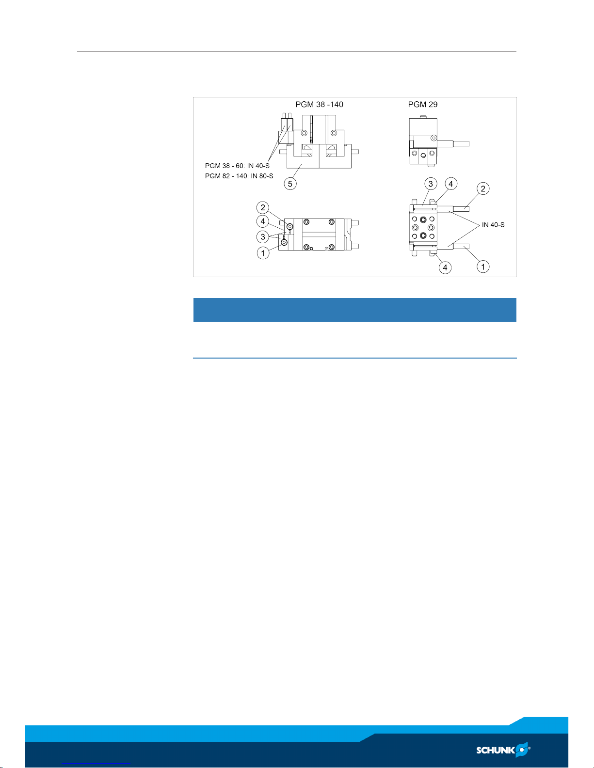
Assembly of the
proximity switch
The switching points of the "open" and "closed" position were set
at the factory by SCHUNK.
NOTICE
The sensor may become damaged then the gripper os operated.
Observe the steps for mounting the sensor.
Gripper open:
Ø Set the gripper in position "open".
Ø Carefully push proximity switch 1 (1) into the bracket (3) until it
touches the base jaq (5).
Ø Pull proximity switch 1 (1) back again by approx. 0.5mm.
Ø Fasten the proximity switch by tightening the screw (4). Tighten
the screw (4) with max. 30Ncm.
Ø Test the function by closing the gripper and then opening it
again.
Gripper closed:
Ø Set the gripper in position "closed".
Ø Carefully push proximity switch 2 (2) into the bracket (3) until it
touches the base jaw (5).
Ø Pull proximity switch 2 (2) back again by approx. 0.5mm.
Ø Fasten the proximity switch by tightening the screw (4). Tighten
the screw (4) with max. 30Ncm.
Ø Test the function by closing the gripper and then opening it
again.
Page 16
Assembly
16
04.00 | PGM 29 - 140 | Assembly and Operating Manual | en | 389284
4.3.2 Programmable magnetic switch (MMS-P)
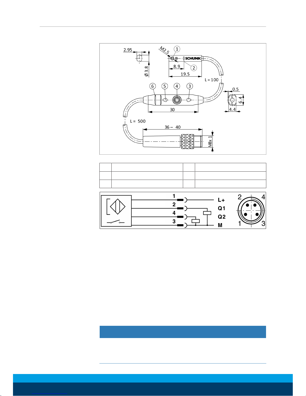
Magnetic switch MMS-P 22
1 Mounting screw 4 Teach-button
2 Center sensor elements 5 LED display
3 LED display 6 Ribs for cable tires
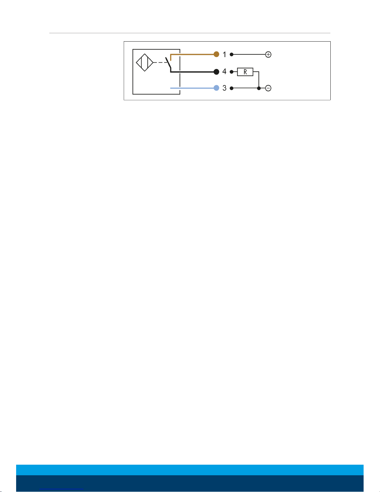
brown
white
black
blue
Connection diagram PNP-4 conductor (MMS-P 22)
Types available for order (see catalog):
• MMS-P 22-S-M8-PNP
• MMSK-P 22-S-PNP
• V2-M8-4-2XM8-3
The MMSK-P 22-S-PNP features a cable with open strands so that
it can be connected via terminal contacts.
The V2-M8-4-2XM8-3 distributor is used to convert the 4-pin
connector plug of the MMS-P 22-S-M8-PNP sensor to two
standard M8 plugs with 3 pins each.
Mounting of the
sensor
NOTICE
Sensor can be damaged during assembly.
• Do not exceed the maximum tightening torque of 10 Ncm for
the set screws!
Page 17
Assembly
04.00 | PGM 29 - 140 | Assembly and Operating Manual | en | 389284
17
NOTE
Ferromagnetic material changes the switching positions of the
sensor (e.g. Adapter plate made of ordinary steel).
For ferromagnetic adapter plates:
• The module must be first mounted on the adapter plate.
• Then, the position of the magnetic switchs has to be set.
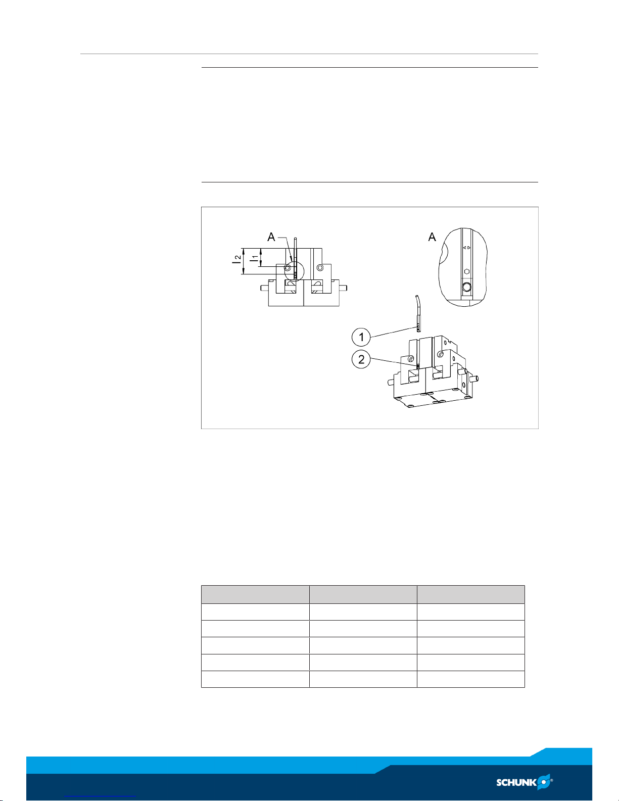
Ø Slide or turn in the magnetic switch (1) into the groove until it
bears against the stop (2) (if available).
Ø If there is no terminal stop, then slide the magnetic switch
according to dimension l2 (bottom edge of gripper up to front
side of sensor) or according to dimension l1 (bottom edge of
gripper up to double arrow on sensor) and then clamp with the
mounting screw.
Type Maß l
1
Maß l
2
PGM 60 23.9 32.8
PGM 82 21.3 30.2
PGM 96 27.4 36.3
PGM 120 26.9 35.8
PGM 140 34.2 43.1
Page 18
Assembly
18
04.00 | PGM 29 - 140 | Assembly and Operating Manual | en | 389284
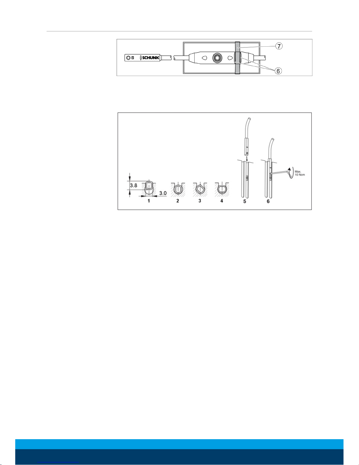
Ø To relieve the cable, the electronics have to be fixed in place
using cable ties (7).
There are ribs (6) in place on the electronics for mounting
purposes.
Ø Turn in the sensor (1 - 4).
OR
Push the sensor axially into the slot until it contacts the stop (5).
Ø Fix the sensor with an Allen wrench (6).
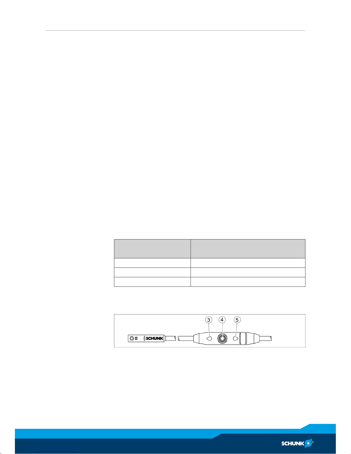
Ø Keep the Teach-Button (4) pressed for 2 seconds.
✓ After 2 seconds flashing LED 1 (3).
Ø Move the gripper into position 1 (e.g. "0 - position").
Ø Press the Teach-Button (4) briefly.
✓ LED 1 (3) lights up and LED 2 (5) is flashing.
Ø Move the gripper manually into position 2 (e.g. "-2mm").
✓ LED 1 (3) should turn out as soon as the switching point 1 is
left.
Ø Press the Teach-Button (4) briefly.
✓ LED 2 (5) lights up.
✔ The switching points are set.
Page 19
Assembly
04.00 | PGM 29 - 140 | Assembly and Operating Manual | en | 389284
19
Adjusting the
hysteresis
The hysteresis to both switching points will be adjusted
automatically corresponding to the characteristics of the magnetic
field.
The user can set the switching and trigging points of each position
a little bit closer than for the automatic mode. The trigging point is
closer to the switching point. At the same time the susceptibility to
trouble and damage increases. In the mode of the lowest
hysteresis, an error signal (such as jitter or untimely switch off) can
be avoided, if the sensor is protected against all types of
disturbances (i.e. by shielding). Frequent types of disturbances are
change in temperature and electro-magnetic influences.
Within the closest fine-teach mode, SCHUNK cannot guarantee
EMC-compatibility any more.
The hysteresis adjustment is used for the manual adjustment of
the switching points (if necessary).
In case that the hysteresis automatically determined by the sensor
should be too high or too low after “the adjustment of the
switching points”, you may correct the value as follows.
The sensor avoids a too small hysteresis during hysteresis
adjustment.
Sensors MMS 22, MMS-P 22, MMS 22-PI1 and MMS 22-PI2
The smallest detectable difference in stroke is defined in the
following table:
The smallest detectable difference in stroke based on the nominal stroke
For grippers with X mm
nominal stroke per jaw
Min. query range per jaw/
min. queried stroke difference per jaw
X ≤ 5 mm 30% of the nominal stroke per jaw
X > 5 mm to X ≤ 10 mm 20% of the nominal stroke per jaw
X > 10 mm 10% of the nominal stroke per jaw
Example: Product with 7 mm nominal stroke per jaw
7 mm * 20% = 1.4 mm
Page 20

Assembly
20
04.00 | PGM 29 - 140 | Assembly and Operating Manual | en | 389284
Ø Press the Teach-button (4) for 5 seconds.
✓ LED 1 (3) will flash up after 2 seconds.
✓ LED 1 will stop after 5 seconds.
Ø Release the Teach-button.
Ø Put the gripper to position "switch-off point of switching point
1".
Ø Press the Teach-Button (4) briefly. LED 1 (3) will light up twice.
Ø Put the gripper to position "switch-off point of switching point
2".
Ø Press the Teach-Button (4) briefly.
✓ LED 1 (3) will light up twice.
✔ The mounting of the sensor MMS-P is completed.
Page 21
Troubleshooting
04.00 | PGM 29 - 140 | Assembly and Operating Manual | en | 389284
21
5 Troubleshooting
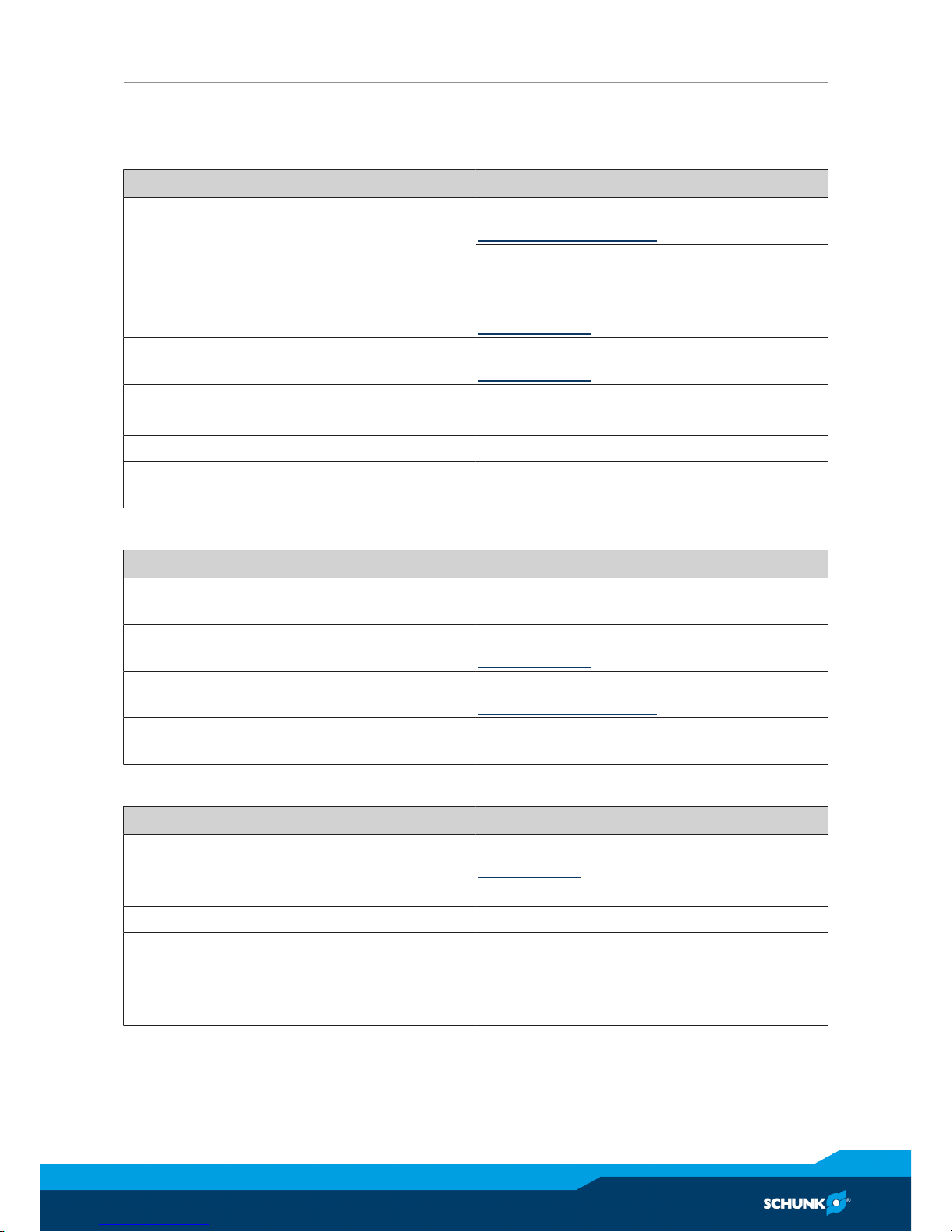
5.1 Product is not moving
Possible cause Corrective action
Base jaws jam in housing, e.g. mounting
surface is not sufficiently even.
Check the evenness of the mounting surface.
Mechanical connection [}11]
Loosen the mounting screws of the product
and actuate the product again.
Pressure drops below minimum. Check air supply.
Air connection [}12]
Compressed air lines switched. Check compressed air lines.
Air connection [}12]
Proximity switch defective or set incorrect. Readjust or change sensor.
Unused air connections open. Close unused air connections.
Flow control valve closed. Open the flow control valve.
Component part defective. Replace component or send it to SCHUNK
for repair.
5.2 The module does not travel through the entire stroke?
Possible cause Corrective action
Dirt deposits between basic jaws and
guidance.
Disassemble and clean the product.
Pressure drops below minimum. Check air supply.
Air connection [}12]
Mounting surface is not sufficiently flat. Check the evenness of the mounting surface.
Mechanical connection [}11]
Components have come loose e.g. due to
overloading.
Completely replace the module
5.3 Product opens or closes abruptly
Possible cause Corrective action
Too little grease in the mechanical guiding
areas.
Clean and lubricate product.
Maintenance [}23]
Compressed air lines blocked. Check compressed air lines of damage.
Mounting surface is not sufficiently flat. Check the evenness of the mounting surface.
One-way flow control valve is missing or
adjustet incorrectly.
Install and adjust one-way flow control
valve.
Loading too large. Check permissible weight and length of the
gripper fingers.
Page 22

Troubleshooting
22
04.00 | PGM 29 - 140 | Assembly and Operating Manual | en | 389284
5.4 Gripping force is dropping
Possible cause Corrective action
Compressed air can escape. Check seals, if necessary, disassemble the
product and replace seals.
Too much grease in the mechanical
movement space.
Clean and lubricate product.
Maintenance [}23]
Pressure drops below minimum. Check air supply.
Link Pneumatischer Anschluss
Component part defective. Replace component or send it to SCHUNK
for repair.
5.5 Product does not achieve the opening and closing times
Possible cause Corrective action
Compressed air lines are not installed
optimally.
If present: Open the flow control couplings
on the product to the maximum that the
movement of the jaws occurs without
bouncing and hitting.
Check compressed air lines.
Inner diameters of compressed air lines are
of sufficient size in relation to compressed
air consumption.
Keep compressed air lines between the
product and directional control valve as
short as possible.
Flow rate of valve is sufficiently large
relative to the compressed air consumption.
NOTICE!The throttle check valve must not
be removed, even if the product has not
reached the opening and closing times.
If, despite optimum air connections, the
opening and closing times specified in the
catalogue are not achieved, SCHUNK
recommends the use of quick-air-vent-
valves directly at the product.
Loading too large. Check permissible weight and length of the
gripper fingers.
Page 23
Maintenance
04.00 | PGM 29 - 140 | Assembly and Operating Manual | en | 389284
23
6 Maintenance
6.1 Notes
Original spare parts
Use only original spare parts of SCHUNK when replacing spare and
wear parts.
Exchange of housing and base jaws
The base jaws and the guidance in the housing are matched. To
exchange these parts, send the product with a repair order to
SCHUNK or order the housing with the base jaws as a set.
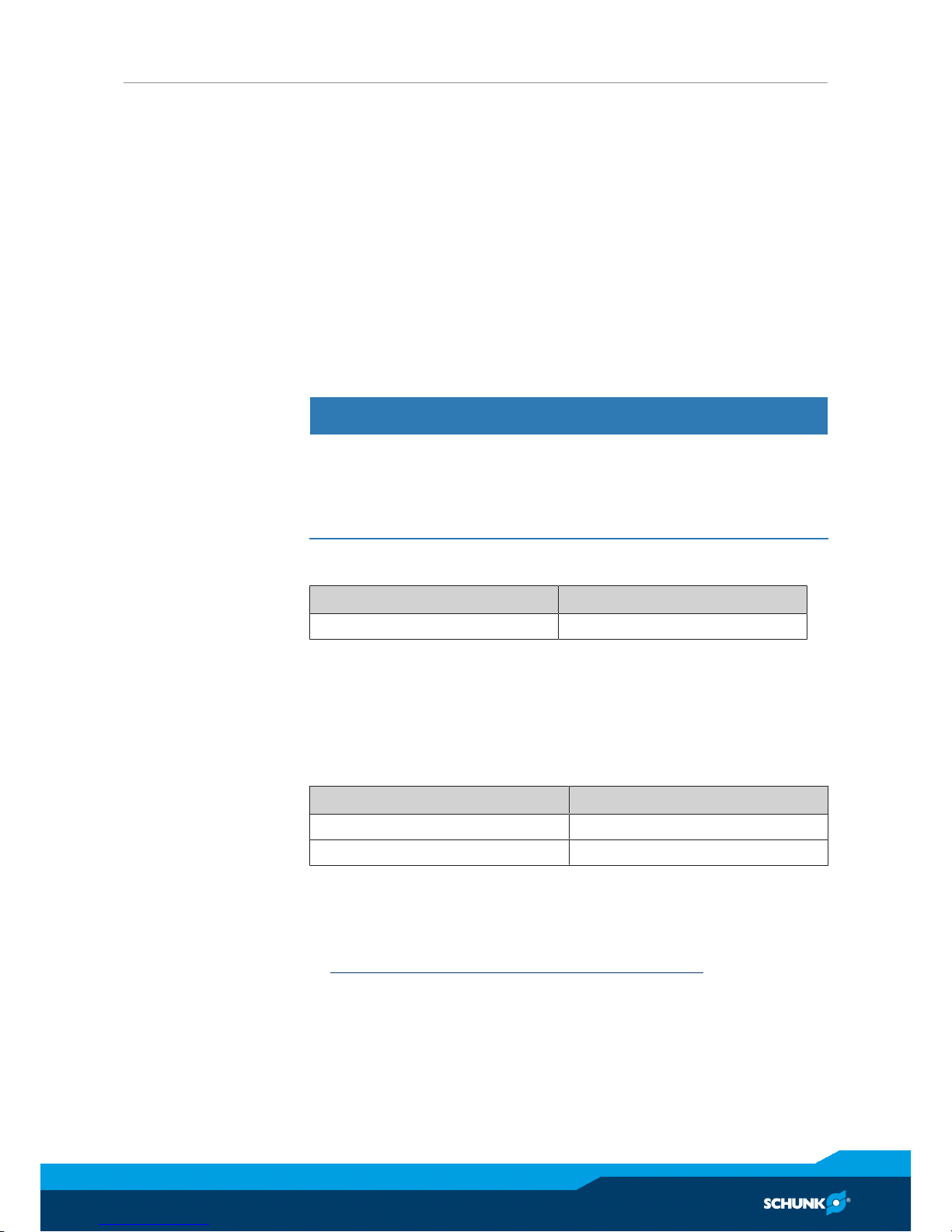
6.2 Maintenance and lubrication intervals
NOTICE
Material damage due to hardening lubricants!
Lubricants harden more quickly at temperatures above 60°C,
leading to possible product damage.
• Reduce the lubricant intervals accordingly.
Size 29 - 140
Interval [Mio. cycles] 2
6.3 Lubricants/Lubrication points (basic lubrication)
SCHUNK recommends the lubricants listed.
During maintenance, treat all greased areas with lubricant. Thinly
apply lubricant with a lint-free cloth.
Lubricant point Lubricant
Metallic sliding surfaces microGLEIT GP 360
All seals Renolit HLT 2
6.4 Servicing the module
Maintenance
• Clean all parts thoroughly and check for damage and wear.
• Treat all greased areas with lubricant.
Lubricants/Lubrication points (basic lubrication) [}23]
• Oil or grease bare external steel parts.
Page 24
Translation of original declaration of incorporation
24
04.00 | PGM 29 - 140 | Assembly and Operating Manual | en | 389284
7 Translation of original declaration of incorporation
in terms of the Directive 2006/42/EG, Annex II, Part 1.B of the European Parliament and of
the Council on machinery.
Manufacturer/
Distributor
SCHUNK GmbH & Co. KG Spann- und Greiftechnik
Bahnhofstr. 106 – 134
D-74348 Lauffen/Neckar
We hereby declare that on the date of the declaration the following partly completed
machine complied with all basic safety and health regulations found in the directive
2006/42/EC of the European Parliament and of the Council on machinery. The declaration
is rendered invalid if modifications are made to the product.
Product designation: 2-Finger Parallel Gripper / PGM 29 - 140 / pneumatic
ID number 0302680 ... 0302687
The partly completed machine may not be put into operation until conformity of the
machine into which the partly completed machine is to be installed with the provisions of
the Machinery Directive (2006/42/EC) is confirmed.
Applied harmonized standards, especially:
EN ISO 12100:2010 Safety of machinery - General principles for design -
Risk assessment and risk reduction
The manufacturer agrees to forward on demand the relevant technical documentation for
the partly completed machinery in electronic form to national authorities.
The relevant technical documentation according to AnnexVII, Part B, belonging to the
partly completed machinery, has been created.
Person authorized to compile the technical documentation:
Robert Leuthner, Address: see manufacturer's address
Lauffen/Neckar, January 2019 p.p. Ralf Winkler,
Manager for development
of gripping system components
Page 25
Annex to Declaration of Incorporation
04.00 | PGM 29 - 140 | Assembly and Operating Manual | en | 389284
25
8 Annex to Declaration of Incorporation
according 2006/42/EG, Annex II, No. 1 B
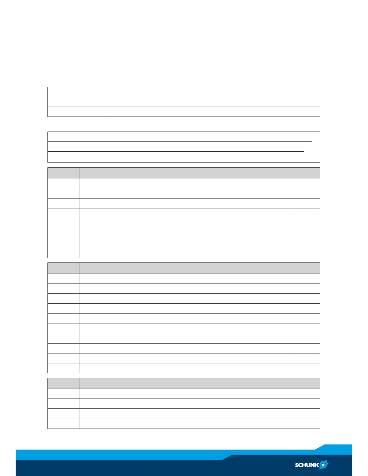
1.Description of the essential health and safety requirements pursuant to 2006/42/EC,
Annex I that are applicable and that have been fulfilled with:
Product designation 2-Finger Parallel Gripper
Type designation PGM
ID number 0302680 ... 0302687
To be provided by the System Integrator for the overall machine ⇓
Fulfilled for the scope of the partly completed machine ⇓
Not relevant ⇓
1.1 Essential Requirements
1.1.1 Definitions X
1.1.2 Principles of safety integration X
1.1.3 Materials and products X
1.1.4 Lighting X
1.1.5 Design of machinery to facilitate its handling X
1.1.6 Ergonomics X
1.1.7 Operating positions X
1.1.8 Seating X
1.2 Control Systems
1.2.1 Safety and reliability of control systems X
1.2.2 Control devices X
1.2.3 Starting X
1.2.4 Stopping X
1.2.4.1 Normal stop X
1.2.4.2 Operational stop X
1.2.4.3 Emergency stop X
1.2.4.4 Assembly of machinery X
1.2.5 Selection of control or operating modes X
1.2.6 Failure of the power supply X
1.3 Protection against mechanical hazards
1.3.1 Risk of loss of stability X
1.3.2 Risk of break-up during operation X
1.3.3 Risks due to falling or ejected objects X
1.3.4 Risks due to surfaces, edges or angles X
Page 26

Annex to Declaration of Incorporation
26
04.00 | PGM 29 - 140 | Assembly and Operating Manual | en | 389284
1.3 Protection against mechanical hazards
1.3.5 Risks related to combined machinery X
1.3.6 Risks related to variations in operating conditions X
1.3.7 Risks related to moving parts X
1.3.8 Choice of protection against risks arising from moving parts X
1.3.8.1 Moving transmission parts X
1.3.8.2 Moving parts involved in the process X
1.3.9 Risks of uncontrolled movements X
1.4 Required characteristics of guards and protective devices
1.4.1 General requirements X
1.4.2 Special requirements for guards X
1.4.2.1 Fixed guards X
1.4.2.2 Interlocking movable guards X
1.4.2.3 Adjustable guards restricting access X
1.4.3 Special requirements for protective devices X
1.5 Risks due to other hazards
1.5.1 Electricity supply X
1.5.2 Static electricity X
1.5.3 Energy supply other than electricity X
1.5.4 Errors of fitting X
1.5.5 Extreme temperatures X
1.5.6 Fire X
1.5.7 Explosion X
1.5.8 Noise X
1.5.9 Vibrations X
1.5.10 Radiation X
1.5.11 External radiation X
1.5.12 Laser radiation X
1.5.13 Emissions of hazardous materials and substances X
1.5.14 Risk of being trapped in a machine X
1.5.15 Risk of slipping, tripping or falling X
1.5.16 Lightning X
1.6 Maintenance
1.6.1 Machinery maintenance X
1.6.2 Access to operating positions and servicing points X
1.6.3 Isolation of energy sources X
1.6.4 Operator intervention X
1.6.5 Cleaning of internal parts X
Page 27

Annex to Declaration of Incorporation
04.00 | PGM 29 - 140 | Assembly and Operating Manual | en | 389284
27
1.7 Information
1.7.1 Information and warnings on the machinery X
1.7.1.1 Information and information devices X
1.7.1.2 Warning devices X
1.7.2 Warning of residual risks X
1.7.3 Marking of machinery X
1.7.4 Instructions X
1.7.4.1 General principles for the drafting of instructions X
1.7.4.2 Contents of the instructions X
1.7.4.3 Sales literature X
The classification from Annex 1 is to be supplemented from here
forward.
2 Supplementary essential health and safety requirements for certain
categories of machinery
X
2.1 Foodstuffs machinery and machinery for cosmetics or pharmaceutical
products
X
2.2 Portable hand-held and/or guided machinery X
2.2.1 Portable fixing and other impact machinery X
2.3 Machinery for working wood and material with similar physical
characteristics
X
3 Supplementary essential health and safety requirements to offset
hazards due to the mobility of machinery
X
4 Supplementary essential health and safety requirements to offset
hazards due to lifting operations
X
5 Supplementary essential health and safety requirements for machinery
intended for underground work
X
6 Supplementary essential health and safety requirements for machinery
presenting particular hazards due to the lifting of persons
X
Page 28

28
04.00 | PGM 29 - 140 | Assembly and Operating Manual | en | 389284
 Loading...