

SCHUNK NSE mini 90, NSE-M mini 90, NSE mini 90-V1, NSE-M mini 90-V1 Assembly And Operating Manual
Page 1

Translation of Original Operating Manual
VERO-S quick-change pallet system
NSE mini 90, NSE-M mini 90
Assembly and Operating Manual
Superior Clamping and Gripping
Page 2

Imprint
2
02.00|NSE mini 90, NSE-M mini 90 |en
Imprint
Copyright:
This manual is protected by copyright. The author is SCHUNK GmbH & Co. KG. All rights
reserved. Any reproduction, processing, distribution (making available to third parties),
translation or other usage - even excerpts - of the manual is especially prohibited and
requires our written approval.
Technical changes:
We reserve the right to make alterations for the purpose of technical improvement.
Document number: 1372754
Version: 02.00 |19/09/2018|en
© H.-D. SCHUNK GmbH & Co.
All rights reserved.
Dear Customer,
thank you for trusting our products and our family-owned company, the leading
technology supplier of robots and production machines.
Our team is always available to answer any questions on this product and other solutions.
Ask us questions and challenge us. We will find a solution!
Best regards,
Your SCHUNK team
H.-D. SCHUNK GmbH & Co.
Spanntechnik KG
Lothringer Str. 23
D-88512 Mengen
Tel. +49–7572-7614-0
Fax +49-7572-7614-1099
[email protected]
schunk.com
Page 3

Table of Contents
02.00|NSE mini 90, NSE-M mini 90 |en
3
Table of Contents
1
General .................................................................................................................... 5
1.1
Warnings ................................................................................................................... 5
1.2
Applicable documents .............................................................................................. 6
2
Basic safety notes ..................................................................................................... 7
2.1
Intended use ............................................................................................................. 7
2.2
Not intended use ...................................................................................................... 7
2.3
Notes on particular risks ........................................................................................... 8
2.4
Product safety......................................................................................................... 11
2.4.1
Holding force and screw strength ............................................................... 11
2.4.2
Using personal protective equipment ........................................................ 12
2.5
Personnel qualification ........................................................................................... 12
2.6
Organizational measures ........................................................................................ 12
2.7
Using personal protective equipment .................................................................... 13
3
Warranty ................................................................................................................. 14
4
Scope of delivery ..................................................................................................... 14
4.1
Accessories ............................................................................................................. 14
5
Technical data ......................................................................................................... 15
6
Assembly ................................................................................................................. 16
6.1
Pre-assembly measures .......................................................................................... 16
6.2
General assembly notes ......................................................................................... 16
6.3
Fastening and connection ...................................................................................... 18
6.3.1
Fastening and connection NSE mini 90 ....................................................... 22
6.3.2
Fastening and connection NSE-M mini 90 .................................................. 22
6.3.3
Fastening and NSE mini 90-V1, NSE-M mini 90-V1 connection ................. 22
6.4
SPA 20 mini, SPB 20 mini, SPC 20 mini clamping bolts .......................................... 23
6.5
Note about pallet changing .................................................................................... 25
6.6
Pneumatic circuit diagram...................................................................................... 26
7
Function .................................................................................................................. 28
7.1
Clamping functions in the pneumatically actuated clamping system ................... 28
7.2
Clamping functions with the manually actuated clamping system ....................... 29
7.3
Clamping slide position monitoring ....................................................................... 30
8
Maintenance and care ............................................................................................. 32
8.1
Ambient conditions and operating conditions ....................................................... 33
9
Troubleshooting ...................................................................................................... 34
9.1
Malfunctions in the pneumatically actuated clamping system ............................. 34
Page 4

Table of Contents
4
02.00|NSE mini 90, NSE-M mini 90 |en
9.1.1
Emergency unlocking in case of malfunctions in the pneumatically
actuated clamping system .......................................................................... 34
9.2
Malfunctions in the manually actuated clamping system ..................................... 35
9.2.1
Emergency unlocking in case of malfunctions in the manually actuated
clamping system .......................................................................................... 35
10
Seal kit and part lists ............................................................................................... 37
10.1
Seal kit lists ............................................................................................................. 37
10.2
Parts lists ................................................................................................................. 37
11
Drawings ................................................................................................................. 40
12
Translation of original EC declaration of incorporation ............................................ 43
Page 5

General
02.00|NSE mini 90, NSE-M mini 90 |en
5
General
This operating manual is an integral component of the product and
contains important information on safe and proper assembly,
commissioning, operation, care, maintenance and disposal. This
manual must be stored in the immediate vicinity of the product
where it is accessible to all users at all times.
Before using the product, read and comply with this manual,
especially the chapter “Basic safety notes”.( 2, Page 7)
If the product is passed on to a third party, these instructions must
also be passed on.
Illustrations in this manual are provided for basic understanding of
the product and may differ from the actual product design.
We accept no liability for damage resulting from the failure to
observe and comply with this operating manual.
Warnings
To make risks clear, the following signal words and symbols are
used for safety notes.
DANGER
Danger for persons!
Non-observance will inevitably cause irreversible injury or death.
WARNING
Dangers for persons!
Non-observance can lead to irreversible injury and even death.
CAUTION
Dangers for persons!
Non-observance can cause minor injuries.
NOTICE
Material damage!
Information about avoiding material damage.
1
1.1
Page 6

General
6
02.00|NSE mini 90, NSE-M mini 90 |en
WARNING
Warning about hand injuries
WARNING
Warning about hot surfaces
Applicable documents
General terms of business
Katalogdatenblatt des gekauften Produkts
The documents listed here, can be downloaded on our homepage
www.schunk.com
1.2
Page 7

Basic safety notes
02.00|NSE mini 90, NSE-M mini 90 |en
7
Basic safety notes
Risks to persons and property may arise from incorrect handling,
assembly and adjustment of this product if these instructions are
disregarded.
Report breakdowns and damages as soon as you detect it and
repair immediately, so as to keep the extent of damage as small as
possible and to avoid risking the safety of the product.
Only original SCHUNK spare parts may be used.
Intended use
This product is intended solely for positioning and clamping
workpieces or clamping pallets on machine tools or other suitable
technical devices.
• The product may only be used within the scope of its technical
data, ( 5, Page 15).
• The product is intended for industrial and industry-oriented
use.
• Appropriate use of the product includes compliance with all
instructions in this manual.
Not intended use
The product is not being used as intended if, for example:
• It is used as a pressing tool, a chuck, a load-handling device or
as lifting equipment.
• It is used for turning applications without consulting SCHUNK.
• It is used in working environments that are not permissible.
• People work on machines or technical equipment that do not
comply with the EC Machinery Directive 2006/42/EC,
disregarding the applicable safety regulations.
• The technical data specified by the manufacturer are exceeded
during usage.
2
2.1
2.2
Page 8

Basic safety notes
8
02.00|NSE mini 90, NSE-M mini 90 |en
Notes on particular risks
This product may pose a danger to persons and property if, for
example:
• It is not used as intended;
• It is not installed or maintained properly;
• The safety and installation instructions, local applicable safety
and accident prevention regulations or the EC Machinery
Directive are not observed.
WARNING
Risk of injury due falling parts during transport, assembly and
disassembly the Quick-Change Pallet System.
Improperly secured parts can break off and fall.
• Use a suitable lifting equipment and transport.
• During transport do not step into the danger area.
• Wear personal protective equipment.
WARNING
Risk of injury to persons due to falling down of the fixture, pallet
or workpiece by erroneous or negligent loosening of the
clamping pins.
• During operation, incorrect or incautious loosening of the
clamping pin must be prevented by suitable measures
(disconnection of power supply after locking, use of safety
valves or safety switches).
• The machines and facilities must fulfill the minimum
requirements of the EC Machinery Directive 2006/42/EC;
specifically, they must have effective technical measures to
protect against possible mechanical hazards.
• Wear personal protective equipment.
2.3
Page 9

Basic safety notes
02.00|NSE mini 90, NSE-M mini 90 |en
9
WARNING
Risk of injury to persons during transport of the system and in
case of horizontally placed clamping pin axis or overhead
applications due to falling down of the fixture or pallet.
• Use a crane or trolley for transport.
• In case of horizontal or overhead applications, secure the
fixture or pallet against falling down during loosening the
clamping modules.
WARNING
The system is spring-packaged. Risk of injury due to
independent motions of components into its end positions after
pressing the “Emergency stop” or switching off or failure of the
energy supply.
• Wait until the system stops completely.
• Do not reach into the clamping modules.
• Use pressure maintenance valves.
CAUTION
Risk of injury due impurities (e.g. metal shavings) in the exhaust
and air purge ports of the clamping station.
• The danger zone must be surrounded by a protective
enclosure during operation.
• Wear personal protective equipment (safety goggles).
CAUTION
Danger of injury due to loosening of incorrectly connected
compressed air hoses.
• Wear safety valves or safety switches.
• The danger zone must be surrounded by a protective
enclosure during operation.
Page 10
Basic safety notes
10
02.00|NSE mini 90, NSE-M mini 90 |en
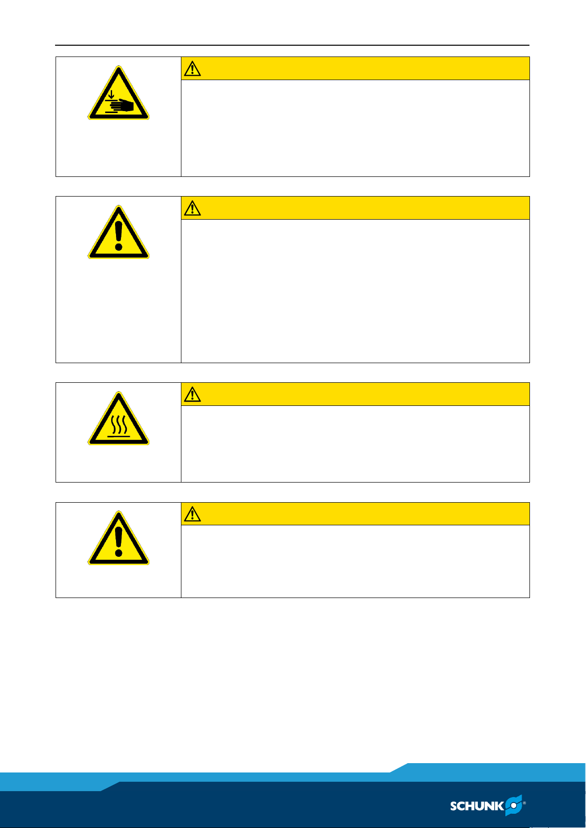
CAUTION
There is a risk of limbs being crushed during manual loading and
unloading of moving parts and during the clamping process.
• Do not reach into the clamping pin holder.
• Use loading aids.
• Wear protective gloves.
CAUTION
Risk of slipping or falling if the chuck's operational environment
is not clean (e.g. contaminated with cooling lubricants or oil).
• Ensure that the working environment is clean before starting
assembly and installation work.
• Wear suitable safety boots.
• Follow the safety and accident-prevention regulations when
operating the chuck, especially when working with machine
tools and other technical equipment.
CAUTION
Risk of burns due to workpieces with high temperatures
Workpieces with high temperatures pose the risk of burns.
• Wear protective gloves when removing the workpieces.
• Automatic loading is preferred.
CAUTION
Risk of exposure to pneumatic´s exhaust noise
Noise from air system and pneumatic equipment during the
machining process.
• Wear hearing protection.
Page 11

Basic safety notes
02.00|NSE mini 90, NSE-M mini 90 |en
11
Product safety
• Disconnect the energy supply lines and ensure that there is no
residual energy in the system when performing assembly,
modification, maintenance, or adjustment work.
• Perform maintenance work, modifications, and attachments
outside the danger zone.
• During all work, secure the system against accidental start-up.
• Do not reach into the open mechanical parts of the clamping
pin holder.
• All assembly, modifications and disassembly must be
performed by trained personnel.
Maintenance instructions
The maintenance and servicing intervals must always be complied
with. The intervals indicated refer to a standard working
environment. Operating the gripper in an environment in which it
is subjected to abrasive dusts or corrosive and/or aggressive
vapours and/or liquids requires the prior consent of SCHUNK.
Safety during assembly and maintenance
During assembly, connection, setting, commissioning and testing,
it is important to eliminate the possibility of the fitter or any other
persons accidentally activating the system.
Refrain from all work that could threaten safety.
Holding force and screw strength
The holding force of the System is essentially limited by the
strength of the screwed connections with which the clamping pin
is connected to the pallet or device. On this basis fastening
screws of the property class 12.9 are to be used only.
Only original SCHUNK Clamping-Pins are to be used.
When the clamping pin is used in the customer’s own assembly
device, the customer is to provide for a sufficiently dimensioned
tap and satisfactory strength of the fastening material.
2.4
2.4.1
Page 12

Basic safety notes
12
02.00|NSE mini 90, NSE-M mini 90 |en
Using personal protective equipment
When using this product, you must comply with the relevant
health and safety at work rules and you must use the required
personal safety equipment (minimum: category 2).
Personnel qualification
The assembly and disassembly, commissioning, operation and
maintenance of the system may be performed only by trained
specialist personnel.
Every person called upon by the operator to work on the system
must have read and understood the complete Assembly and
Operating Manual, especially chapter 2 "Basic safety notes".
Trainees may work on machines and technical equipment in which
a Quick Change Pallet System is installed provided that they are
supervised at all times by qualified specialist personnel.
Organizational measures
Obeying the rules
The operator must employ suitable organizational measures and
instructions in order to ensure that the relevant safety rules are
obeyed by the persons asked to operate, maintain and repair the
product.
Checking the behavior of personnel
The operator must at least occasionally check that the personnel
are behaving in a safety conscious manner and are aware of the
potential hazards.
Danger signs
The operator must ensure that the signs concerning safety and
hazards on the machine where the product is mounted are clearly
legible and are observed.
2.4.2
2.5
2.6
Page 13

Basic safety notes
02.00|NSE mini 90, NSE-M mini 90 |en
13
Faults
If a malfunction occurs in the product and endangers safety, or if a
problem is suspected due to production behavior, the machine on
which the product is mounted must be stopped immediately and
remain shut down until the malfunction has been located and
remedied. Only allow specialists to remedy malfunctions.
Spare parts
Only use original SCHUNK spare parts.
Environmental regulations
The applicable environmental regulations must be observed for all
maintenance and repair work.
Using personal protective equipment
When using this product, you must comply with the relevant
health and safety at work rules and you must use the required
personal safety equipment (minimum: category 2).
2.7
Page 14

Scope of delivery
14
02.00|NSE mini 90, NSE-M mini 90 |en
Warranty
If the product is used as intended, the warranty is valid for 24
months from the ex-works delivery date under the following
conditions:
• Observe the applicable documents ( 1.2, Page 6)
• Observe the ambient conditions and operating conditions,
( 8.1, Page 33)
• Observe the maximum number of clamping cycles
( 5, Page 15)
• Observance of the specified care and maintenance instructions
( 8, Page 32)
Parts touching the workpiece and wear parts are not included in
the warranty.
Scope of delivery
• Quick-change pallet system
NSE mini 90, NSE mini 90-V1,
NSE-M mini 90, NSE-M mini 90-V1
• Assembly and Operating Manual
• Accessory kits
NSE mini 90:
5 O-rings Ø 6 x 1.5
6 cover caps
6 fastening screws M6
NSE-M mini 90:
2 O-rings Ø 6 x 1.5
6 cover caps
6 fastening screws M6
Accessories
(see catalog or data sheets when ordering separately)
Clamping pallets PAL mini
Clamping pins SPA mini, SPB mini, SPC mini
Protective covers SDE mini
Indexing pins IXB V1 PAL mini
Indexing pins IXB V1 WDS mini
Fitting screws PSC mini
Allen wrenches
3
4
4.1
Page 15

Technical data
02.00|NSE mini 90, NSE-M mini 90 |en
15
Technical data
Designation
NSE
mini 90
NSE
mini 90-V1
NSE-M
mini 90
NSE-M
mini 90-V1
ID no.
0435100
0435105
0435140
0435145
Holding force (M6 / M8)*
15 / 25 kN
15 / 25 kN
15 / 25 kN
15 / 25 kN
Pull-in force without turbo
500 N
500 N
1000 N
1000 N
Pull-down force with turbo
1500 N
1500 N
- - Actuation pressure
6 bar
6 bar
- - Unlocking torque
- - 10 Nm
10 Nm
Repeat accuracy
< 0.005 mm
< 0.005 mm
< 0.005 mm
< 0.005 mm
Operating temperature
+ 15°C – + 60°C
Installation position
Any
Noise emission [dB(A)]
≤ 70
Pressure medium
Compressed air, compressed air quality according to ISO
8573-1:7 4 4
* Holding force when fastening the clamping pin with cylindrical
screw – DIN EN ISO 4762/12.9
The operating pressure must not fall below 6 bar.
A separate maintenance unit with oiler must be used for the air
supply.
Warranty and maximum clamping cycles
Duration of warranty
24 Months
Maximum clamping cycles
500 000
5
Page 16

Assembly
16
02.00|NSE mini 90, NSE-M mini 90 |en
Assembly
Pre-assembly measures
Carefully lift the product out of the packaging (e.g. with suitable
lifting equipment).
CAUTION
Risk of injury due to sharp edges and rough or slippery surfaces
Wear personal protective equipment, particularly protective
gloves.
Check that the delivery is complete and that there is no transport
damage.
General assembly notes
The item numbers specified for the corresponding individual
components relate to chapter drawings.( 11, Page 40)
Assembly, dismantling and modification work on the quick-change
pallet system may only be carried out by specialist personnel.
Request our installation drawings if doing the installation yourself.
Disconnect the power supply lines and ensure that there is no
residual energy in the system before performing assembly,
modification, maintenance, or adjustment work on the
pneumatically actuated quick-change pallet system.
Wear protective equipment (gloves, protective shoes).
Access to the drive piston (pos. 4) on the side must be ensured
during the assembly of the manually actuated quick-change
pallet system, in particular in the event of clamped clamping
pallets. Check whether the drive piston is easy to access in order
to open or close the clamping module prior to the installation.
WARNING
Risk of injury due to dropping the quick-change pallet system
during transport
Transport with care.
6
6.1
6.2
Page 17

Assembly
02.00|NSE mini 90, NSE-M mini 90 |en
17
CAUTION
Risk of injury due to crushing
Install the quick-change pallet system carefully.
Do not place any limbs into the gaps or between the clamping
station and the machine.
If several linked clamping units are mounted, make sure that the
flatness and height deviation of the locating surface from module
to module (based on a gauge of 200 mm) lies within 0.01 mm. The
interface position deviation must not exceed ± 0.015 mm.
Due to redundancy, the clamping pins with positioning accuracy in
one direction (SPB mini 20) should be used for clamping systems
that are more than 160 mm apart or that do not show a
positioning tolerance of ± 0.01 mm. For the clamping areas that
are not intended for alignment of the device or pallet, clamping
pins with centering clearance (SPB mini 20) can be used (also refer
to chapter "Clamping pins SPA 20 mini, SPB 20 mini, SPC 20 mini"
( 6.4, Page 23)).
NOTE
When connecting the pneumatically actuated quick-change pallet
system, ensure that it is only possible to completely ventilate the
piston chamber via the air connection on the base side during the
locking process. The relevant valves or shut-off valves should
therefore be equipped with load relief. This also applies to the
turbo connection.
If the turbo connection is not used, it must be possible to
ventilate the relevant side of the piston. Be sure to take the
ventilation methods into account (see Fig. "Air bleed screw via
turbo connection").
Ventilation via turbo connection
When dismantling the clamping system from the machine table,
the corresponding openings must be secured with set-screws to
prevent ingress of dirt.
If several units are activated via shared hose lines, feed lines with
the following minimum cross-sections must be used.
Page 18

Assembly
18
02.00|NSE mini 90, NSE-M mini 90 |en
Number of modules
At least nominal hose width
1, 2
4 mm
3, 4, 5, 6
6 mm
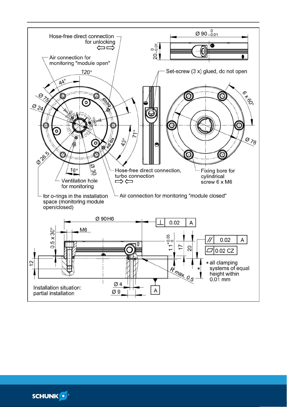
Fastening and connection
The item numbers specified for the corresponding individual
components relate to chapter drawings.( 11, Page 40)
Request our installation drawings if doing the installation of the
module yourself.
6.3
Page 19
Assembly
02.00|NSE mini 90, NSE-M mini 90 |en
19
Fastening and connections NSE mini 90
Page 20
Assembly
20
02.00|NSE mini 90, NSE-M mini 90 |en
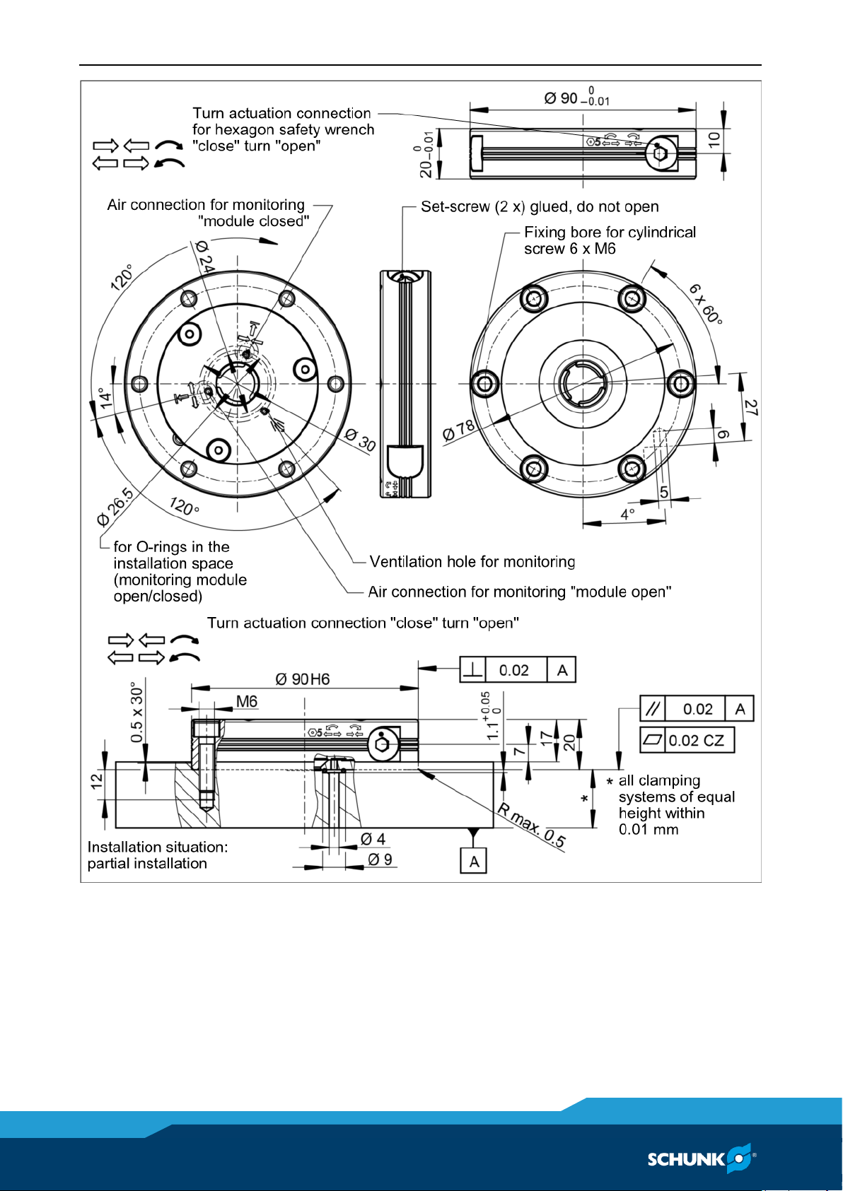
Fastening and connections NSE-M mini 90
Page 21

Assembly
02.00|NSE mini 90, NSE-M mini 90 |en
21
Fastening and connections NSE mini 90-V1, NSE-M mini 90-V1
Page 22

Assembly
22
02.00|NSE mini 90, NSE-M mini 90 |en
Fastening and connection NSE mini 90
The NSE mini 90 is fastened in the installation space by 6 M6
screws (see Fig. "Fastening and connections NSE mini 90").
The assembly module is positioned using the centering diameter of
the installation space: Ø 90H6.
The air connection is made the standard way via the coupling bore
on the lower face side of the quick-change pallet module. This
requires that the bottom opening be sealed with an O-ring, which
is inserted into the O-ring seat in the table top.
Machine the axial sealing O-ring seat according to the following
dimensions: Ø 9
+ 0.1
x 1.1
+ 0.05
.
The accessory pack of the NSE mini 90 contains the O-rings Ø 6 x
1.5 (item 14) for sealing the hose-free direct connections on the
base side.
When the turbo connection is used, the spring-actuated locking
procedure is actively supported with air pressure.
If the turbo connection is not used, the relevant side of the piston
must be able to ventilate.
Fastening and connection NSE-M mini 90
The NSE-M mini 90 is fastened in the installation space by 6 M6
screws (see Fig. "Fastening and connections NSE-M mini 90").
The assembly module is positioned using the centering diameter of
the installation space: Ø 90H6.
As standard, the clamping system is driven manually by rotary
movement at the drive piston (item 4), which is on the side in the
base body (item 1).
The clamping system can be operated by means of a hexagonal
screwdriver (angled pin wrench).
No air supply is required for the operation of the clamping system.
The openings on the base side therefore do not have to be sealed.
Fastening and NSE mini 90-V1, NSE-M mini 90-V1 connection
The NSE mini 90-V1 and NSE-M mini 90-V1 clamping modules have
fitting grooves for position orientation of the clamping pallet.
The modules are fixed in the installation space with 6 M6 screws.
One of them is a mounting location fixed with a fitting
6.3.1
6.3.2
6.3.3
Page 23

Assembly
02.00|NSE mini 90, NSE-M mini 90 |en
23
screw (see fig. "Fastening and connections NSE mini 90-V1, NSE-M
mini 90-V1").
The fitting screw is designed for position orientation and anti-turn
protection of the quick-change pallet module in the installation
space. In the installation space an additional fitting bore is
required for position orientation via the fitting screw.
The Fig. "Fastening and connections NSE mini 90-V1, NSE-M mini
90-V1" below shows how a clamping pallet is connected to the
VERO-S NSE mini 90-V1 quick-change pallet system (NSE-M mini
90-V1). Individual clamping pallets and clamping devices can be
attached to the interface of the VERO-S NSE mini 90-V1.
When producing clamping pallets in-house, pay attention to the
exact positioning clearance of the indexing pin bore to the middle
of the clamping pin. For dimensions, please refer to the
illustration. The indexing pin IXB V1 PAL mini is not included in the
scope of delivery of the quick-change pallet system and must be
ordered separately (see "Accessories" chapter ( 4.1, Page 14)).
SPA 20 mini, SPB 20 mini, SPC 20 mini clamping bolts
NOTICE
Notes on clamping pins and mounting screws
The holding force of the quick-change pallet system is limited
essentially by the tightness of the screw connection which
connects the clamping pin to the pallet or the device. This is why
only screws of strength class 12.9 may be used.
Only original SCHUNK clamping pins may be used.
If the clamping pins are to be used in customer-owned devices,
the customer must provide sufficiently dimensioned threaded
holes or a sufficiently thick mounting material.
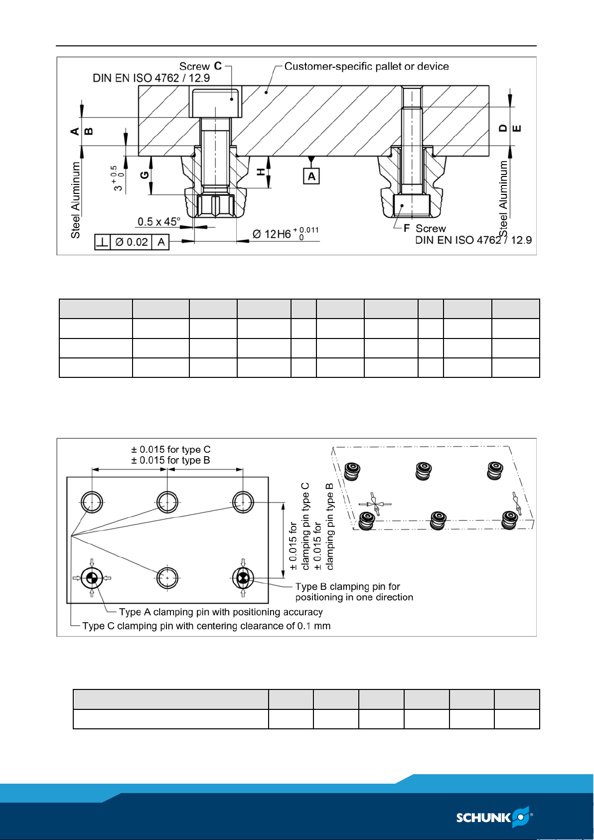
The clamping pins can be attached to the device or pallet in two
different ways. The mounting variant on the left in the illustration,
which is screwed from above, is the preferred variant. With this
variant, if there is a module failure then the device or pallet can be
removed after disassembling the clamping pins.
6.4
Page 24
Assembly
24
02.00|NSE mini 90, NSE-M mini 90 |en
Mounting the clamping pins
Tolerances and installation conditions
Type
ID no.
A B C D E F G H SPA mini 20
0435610
> 8 mm
> 13 mm
M8
> 9 mm
> 11 mm
M6
11 mm
> 8 mm
SPB mini 20
0435620
> 8 mm
> 13 mm
M8
> 9 mm
> 11 mm
M6
11 mm
> 8 mm
SPC mini 20
0435630
> 8 mm
> 13 mm
M8
> 9 mm
> 11 mm
M6
11 mm
> 8 mm
Usage/arrangement of the different types of clamping pins
(Application: pallet with 6 clamping positions)
Tightening torques for mounting clamping pins
(Screw quality 12.9)
Screw size
M6
M8
M10
M12
M14
M16
Tightening torque (Nm)
15
32
62
108
170
262
Page 25
Assembly
02.00|NSE mini 90, NSE-M mini 90 |en
25
Note about pallet changing
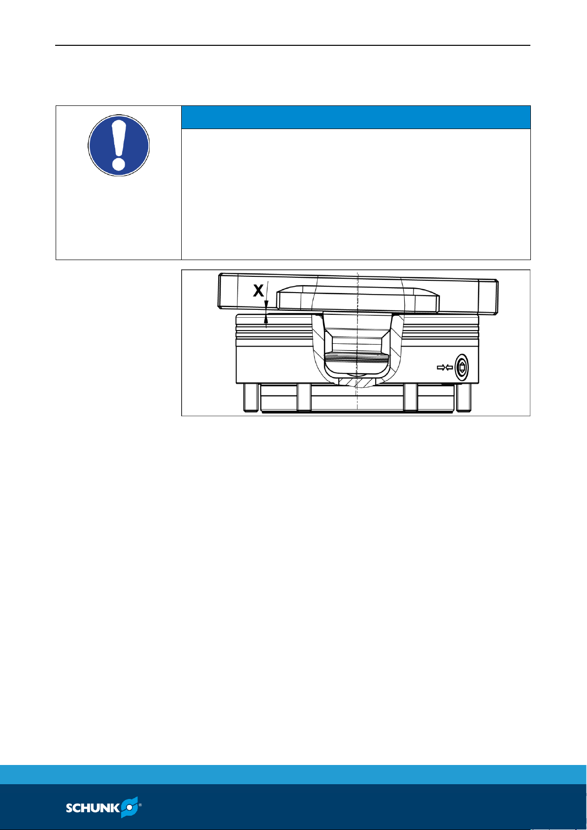
NOTICE
When changing the pallet using lifting equipment or a robot,
ensure that the pallet is lifted exactly parallel to the modules.
The inclination (X) during lifting may not exceed 1.2°.
If the inclination is larger, the clamping pins can jam and the
system components could be damaged or destroyed. In this
case, the system must be inspected and damaged parts must be
replaced immediately.
Only original SCHUNK spare parts may be used!
6.5
Page 26

Assembly
26
02.00|NSE mini 90, NSE-M mini 90 |en
Pneumatic circuit diagram
The pneumatic circuit diagram shows the supply lines and the
pneumatic components for actuating the different functions of the
clamping system. When the monitoring function is connected, the
measurable differential pressure should reach at least 1 bar when
one clamping module is shut down so that secure evaluation can
be performed via the air gap sensor. The maximum pressure of the
monitoring function is 2 bar. In order for the monitoring function
to be actuated, a flow control valve with a preset air volume flow
of approx. 15 l/min must be connected upstream in the feed line.
In order to guarantee reliable evaluation, the pressure and air
volume must be held constant. Pressure fluctuations can affect the
settings of the pressure switch and lead to incorrect measurement
results.
6.6
Page 27

Assembly
02.00|NSE mini 90, NSE-M mini 90 |en
27
The length and cross-section of the line can affect the switching
time of the control components. It may be necessary to readjust
the control components. Check the control components of the
monitoring functions at regular intervals. If errors occur in the
monitoring control system, you must detect the cause of the error.
Page 28

Function
28
02.00|NSE mini 90, NSE-M mini 90 |en
Function
The item numbers specified for the corresponding individual
components relate to chapter drawings.( 11, Page 40)
Clamping functions in the pneumatically actuated clamping
system
The pneumatically actuated clamping system is actuated with
compressed air. An external compressed air supply is required for
it to function.
Unlocking
1 Supply compressed air through the hose-free direct
connection on the base side (operating pressure 6 bar).
2 The clamping slides (item 5) move outward in a radial
direction and release the clamping pin.
3 The pallet can be removed.
The clamping pins are available as separate accessories in three
models (see chapter "Clamping pin SPA 20 mini, SPB 20 mini, SPC
20 mini" Link Spannbolzen). The clamping pins are mounted on
customized pallets or devices.
Locking
1 Depressurize the system.
2 The clamping slides are guided inwards by spring force. When
locking, the pallet is pulled onto the contact surface of the
clamping module and the clamping pin is clamped in the
clamping module in a self-locking and form-fitting manner. It
is therefore not necessary to apply pressure to the clamping
module during machining.
3 When the turbo connection is used, the spring-actuated
locking procedure is actively supported with air pressure. A
turbo impulse is sufficient for a higher pull down force. If the
turbo connection is not used, the relevant side of the piston
must be able to ventilate. The clamping pin is centered at the
taper bore of the clamping module, which is why the angular
alignment of the clamping system can be selected as desired.
7
7.1
Page 29

Function
02.00|NSE mini 90, NSE-M mini 90 |en
29
Clamping functions with the manually actuated clamping
system
The manually actuated clamping system can be operated by
means of a hexagonal screwdriver (angled pin wrench).
No compressed air is required for the function. This makes the
clamping system extremely flexible and allows it to be used
wherever no pressure medium is available.
Unlocking
1 The manually operated clamping system is unlocked by a
rotary movement on the side drive piston (item 4) with the
required unlocking torque (see chapter "Technical Data"
( 5, Page 15)). Insert the spanner wrench into the hexagon
socket of the actuator spindle and turn counter-clockwise.
2 The clamping slides secured by springs (item 7) move
outwards until the final position of the rotary movement
noticeably engages. If the rotary movement is not carried out
to the end position during opening, the drive piston can turn
back and lock the clamping system again.
3 The clamping pin is released.
The clamping pins are available as separate accessories in
three models (see chapter "Clamping pin SPA 20 mini, SPB 20
mini, SPC 20 mini). The clamping pins are mounted on
customized pallets or devices.
4 The pallet can be removed.
Locking
1 The pallet can be inserted in the clamping system as soon as
the clamping slides are unlocked and the rotary movement on
the drive piston noticeably engages.
2 Insert the pallet in the clamping system.
3 Insert the spanner wrench into the hexagon socket of the
actuator spindle and turn clockwise.
4 The clamping slides are guided mechanically inwards by spring
force. When locking, the pallet is pulled onto the contact
surface of the clamping module and the clamping pin is
clamped in the clamping module in a self-locking and formfitting manner. The clamping pin is centered at the taper bore
of the clamping module, which is why the angular alignment
of the clamping system can be selected as desired.
7.2
Page 30

Function
30
02.00|NSE mini 90, NSE-M mini 90 |en
Clamping slide position monitoring
The quick-change pallet systems NSE mini 90 (-V1) and NSE-M mini
90 (-V1) have a standard pressure monitoring of the clamping slide
position.
This way, an electronic differential pressure switch can for
instance be used to monitor the dynamic pressure at the clamping
sides of the quick-change pallet system. This means the slide
position can be monitored electronically in order to ensure that
the clamping slides are in an unlocked position as soon as the
pallet can be lifted. A pressure switch signals to the operator or
the machine which position the clamping slides are in. This way,
the clamping system can be protected from any possible damage.
The air connection is performed as standard via the base-side
connection bore of the quick-change system on the cover (item 2).
For information on sealing the air connection, please refer to
chapter "Fastening and attachment" ( 6.3, Page 18).
Pressure build-up in the "OPEN" and/or "CLOSED" mode. One of
the two monitors, or when necessary both monitoring
connections, can be connected and overseen for mutual security.
Control of the clamping slide monitor requires a reduced pressure
supply limited to 2 bar (see "Pneumatic circuit diagram"
( 6.6, Page 26)).
The measurable differential pressure must reach a minimum of
0.5 bar in order for a reliable evaluation to be done via the air
gap sensor. The maximum pressure is 2 bar.
Monitoring requires a pressure gauge, an adjustable throttle and
an air gap sensor.
The control of the module is performed using the hose-free direct
connections.
For this purpose, the provided connections (see illustrations in
chapters "General assembly instructions" and "Fastening and
connection ( 6.3, Page 18)) must be controlled via bore holes on
the base side and the M3 set-screw in the cover (item 2) must be
removed.
The air bleed screw must lead through an open groove in the table
top. This requires that the bottom opening be sealed with an Oring, which is inserted into the O-ring seat in the table top.
Machine the axial sealing O-ring seat according to the following
dimensions: Ø 9
+ 0.1
x 1.1
+ 0.05
. The accessory pack of the NSE mini
7.3
Page 31
Function
02.00|NSE mini 90, NSE-M mini 90 |en
31
90 contains the O-rings Ø 6 x 1.5 (item 14) for sealing the hosefree direct connections on the base side.
Use of the dynamic pressure monitoring function is not mandatory
for the basic operation of the clamping module.
NOTICE
If the pneumatic monitoring function for monitoring the
clamping slide position is not used, it must be ensured that the
quick-change pallet systems can be loaded or unloaded without
being damaged.
• Before loading or unloading the clamping pallet it must be
ensured that all integrated clamping modules are unlocked.
• Before beginning the machining process it must be ensured
that the integrated clamping modules are locked, and that the
clamping pallet is placed flat on the locating surface.
Monitoring of the operating status can be ensured by lifting or
shaking the clamping pallet.
In the case of clamping modules with manual actuation, attention
must be paid to the correct position of the drive piston (stop limit
on the left or right). A marking with the directions of rotation at
the circumference of the clamping system shows the selected
operating state.
Page 32
Maintenance and care
32
02.00|NSE mini 90, NSE-M mini 90 |en
Maintenance and care
NSE mini 90 and NSE mini 90-V1
The pneumatically actuated quick-change pallet systems NSE mini
90 and NSE mini 90-V1 are designed for low-maintenance
operation, meaning the clamping modules must only be opened or
disassembled in exceptional circumstances.
CAUTION
Risk of injury and risk of damage to the pneumatic clamping
modules when opening the modules.
If a pneumatic clamping module has to be disassembled, send
the module to SCHUNK for repair.
Drive ring and piston are spring preloaded and must only be
removed and installed using a special installation tool by trained
specialist personnel and in line with the appropriate removal
and installation manual.
NSE-M mini 90 and NSE-M mini 90-V1
The manually actuated quick-change pallet systems NSE-M mini 90
and NSE-M mini 90-V1 are designed for low-maintenance
operation, meaning the clamping modules must only be opened or
disassembled in exceptional circumstances.
If disassembly of the manual quick-change pallet systems is
necessary, observe the following instructions:
1 Clean all the parts thoroughly and check for damage and wear.
Replace any damaged or worn parts. Only use original
SCHUNK spare parts.
2 Grease the sliding surfaces of all movable components with
Renolit HLT 2.
To ensure the quick-change pallet system operates perfectly, the
following instructions must be observed:
Pressure medium: Compressed air, compressed air quality
according to ISO 8573-1:7 4 4
NOTICE
A separate maintenance unit with oiler must be used for the air
supply.
8
Page 33

Maintenance and care
02.00|NSE mini 90, NSE-M mini 90 |en
33
Ambient conditions and operating conditions
• Make sure that the contact surfaces of the interface are always
clean.
• Make absolutely sure that no chips of any kind can enter the
interface and that the interface does not fill with cooling
emulsion, which is particularly possible with vertical positioning
of the clamping pin axis. The best way to ensure both of these
is to use the SDE mini 20 or SDE mini 90 protection covers.
If the interface should fill with cooling emulsion, initiate the
unlocking process and dry out the interface in actuated state.
• Only use high-quality cooling emulsions with anti-corrosive
additives during processing.
• Check the units at regular intervals (at least every two weeks or
after 1000 clamping operations). The system is functioning
correctly if the clamping slides move smoothly at minimum
system pressure (6 bar).
• Carry out regular visual/functional checks. In case of visible
damage or signs of malfunction, shut down the quick-change
pallet system immediately. The system may only be started up
again once the faults have been corrected, for instance by
replacement of a damaged module.
8.1
Page 34
Troubleshooting
34
02.00|NSE mini 90, NSE-M mini 90 |en
Troubleshooting
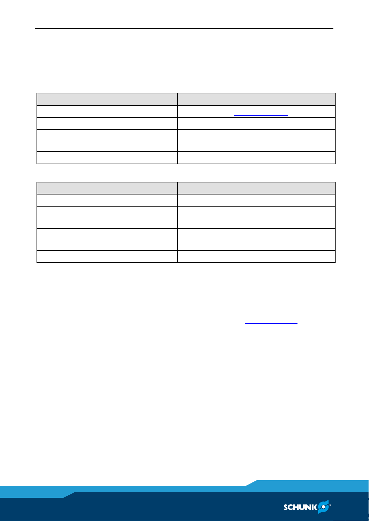
Malfunctions in the pneumatically actuated clamping system
The clamping area does not unlock
Possible cause
Remedial measures
Defective air connections
Check air supply ( 6.3, Page 18)
Pressure below minimum
Check operating pressure (min. 6 bar)
A component is broken (e.g. due to
overloading)
Replace the module or send it to SCHUNK for
repair
Excess tensile load on clamping pins
Reduce support weight
If the clamping area does not unlock perfectly
Possible cause
Remedial measures
Pressure below minimum
Check operating pressure (min. 6 bar)
The module was not operated with oiled
compressed air
Install maintenance unit with oiler
Hose diameter below minimum
For required hose diameters see
chapter "General Assembly Notes"
The turbo connection is still pressurized
Ventilate the connection
Emergency unlocking in case of malfunctions in the
pneumatically actuated clamping system
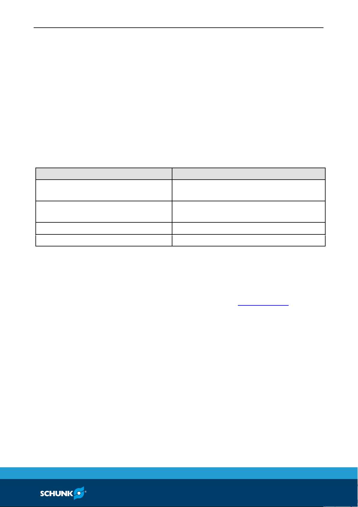
The item numbers specified for the corresponding individual
components relate to chapter drawings.( 11, Page 40)
The pneumatically actuated clamping system can also be manually
unlocked in the case of a functional fault or interrupted air supply.
If the clamping system cannot be unlocked automatically, it is
recommended that you unlock it manually.
At the circumference of the base body (item 1) three set-screws
(item 8) are screwed in at an angle of 3 x 120°. The clamping
system can be unlocked at one of these three accesses.
To manually operate the clamping system, one of these three setscrews must be unscrewed with a hexagon screwdriver.
The piston (item 4) and a compression spring (item 10) are located
behind this set-screw. The piston and the compression spring
must not be removed from the base body.
9
9.1
9.1.1
Page 35
Troubleshooting
02.00|NSE mini 90, NSE-M mini 90 |en
35
In order to initiate unlocking, carefully apply pressure to the end
face of the piston against the spring force with a suitable tool. Now
the clamping system can be opened and the clamping pin is
unlocked.
When assembling the dismantled parts, please make sure that the
O-rings (item 11) installed on the piston are not damaged.
The set-screw (item 8) should be sealed with a screw sealant.
In order to start operation again, detect the cause of error and
clean the clamping system.
Malfunctions in the manually actuated clamping system
The clamping area does not unlock
Possible cause
Remedial measures
Incorrect direction of rotation on the
actuating screw
Change direction of rotation on the actuating
screw
A component is broken (e.g. due to
overloading)
Replace the module or send it to SCHUNK for
repair
Clamping bolt receptacle heavily soiled
Clean clamping pin holder
Excess tensile load on clamping pins
Reduce support weight
Emergency unlocking in case of malfunctions in the manually
actuated clamping system
The item numbers specified for the corresponding individual
components relate to chapter drawings.( 11, Page 40)
The mechanically operated clamping system can also be unlocked
in the event of a malfunction.
If the clamping system cannot be unlocked by turning the drive
piston (item 4) counterclockwise, the emergency release is
recommended.
On the circumference of the base body (item 1), two set-screws
(item 11) are additionally screwed in next to the drive piston (item
4). The clamping system can be unlocked at one of these two
accesses.
To manually operate the clamping system, one of these two setscrews must be unscrewed with a hexagon screwdriver.
The piston (item 8) and a compression spring (item 10) are located
behind this set-screw. The piston and the compression spring
must not be removed from the base body.
9.2
9.2.1
Page 36

Troubleshooting
36
02.00|NSE mini 90, NSE-M mini 90 |en
In order to initiate unlocking, carefully apply pressure to the end
face of the piston against the spring force with a suitable tool. Now
the clamping system can be opened and the clamping pin is
unlocked.
In order to start operation again, detect the cause of error and
clean the clamping system.
Page 37

Seal kit and part lists
02.00|NSE mini 90, NSE-M mini 90 |en
37
Seal kit and part lists
Seal kit lists
NSE mini 90 / NSE mini 90-V1
Item
Designation
Quantity
11
O-ring Ø 7 x 1
6
13
O-ring Ø 62 x 1.5
1
14
O-ring Ø 6 x 1.5
5
Wearing parts - we recommend replacing when maintenance is
performed
Parts lists
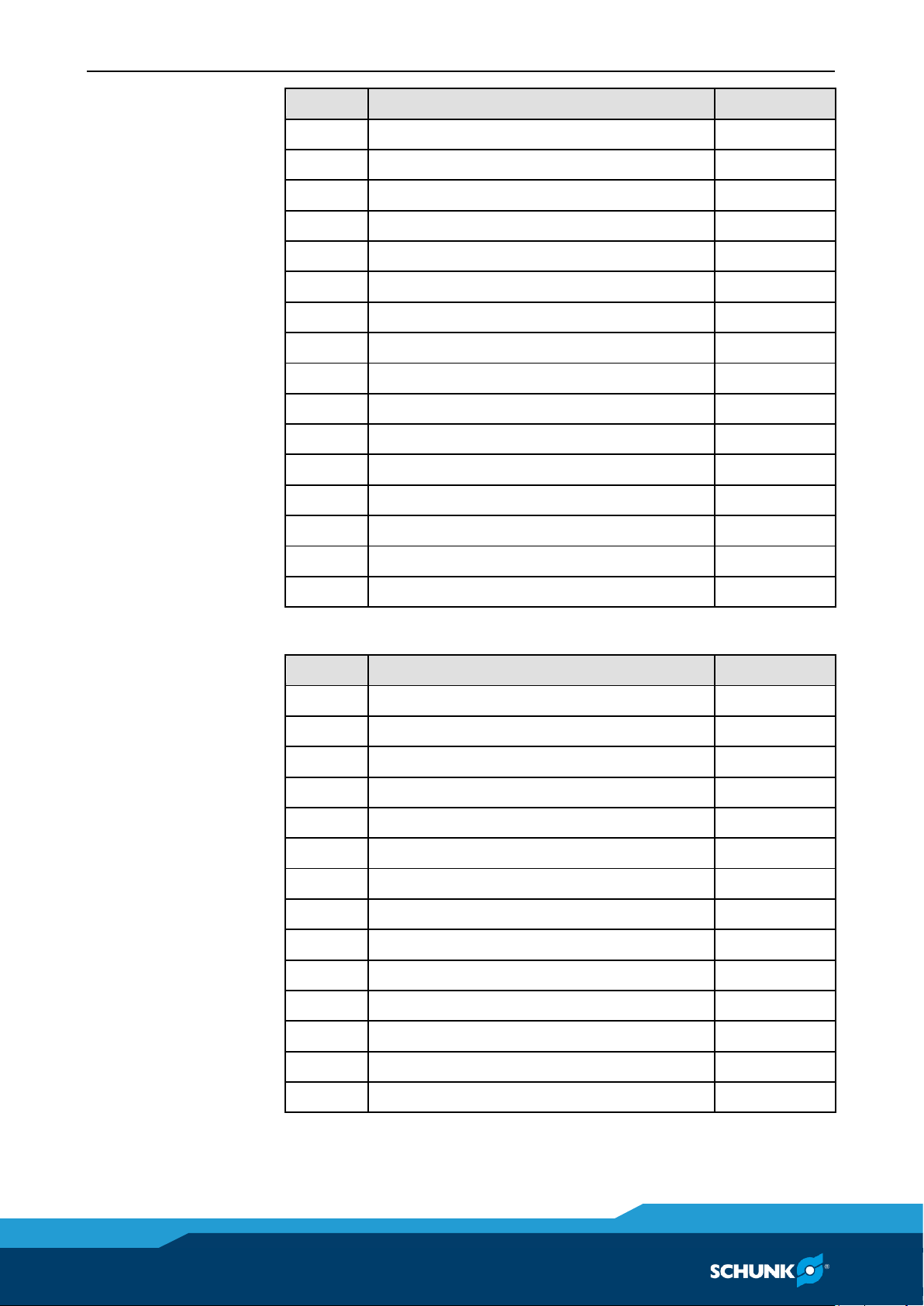
NSE mini 90
Item
Designation
Quantity
1
Base body
1 2 Cover
1 3 Drive ring
1 4 Piston
3 5 Clamping slide
3 7 Countersunk screw
3
8
Set-screw
3 9 Set-screw
3
10
Compression spring
3
11*
O-ring Ø 7 x 1
6
12
Set-screw
5
13*
O-ring Ø 62 x 1.5
1
14*
O-ring Ø 6 x 1.5
5
15
Bearing shell
3
20
Screw
6
21
Cover cap
6
NSE mini 90-V1
Item
Designation
Quantity
1
Base body
1
2
Cover
1
10
10.1
10.2
Page 38
Seal kit and part lists
38
02.00|NSE mini 90, NSE-M mini 90 |en
Item
Designation
Quantity
3
Drive ring
1 4 Piston
3
5
Clamping slide
3 7 Countersunk screw
3 8 Set-screw
3 9 Set-screw
3
10
Compression spring
3
11*
O-ring Ø 7 x 1
6
12
Set-screw
5
13*
O-ring Ø 62 x 1.5
1
14*
O-ring Ø 6 x 1.5
5
15
Bearing shell
3
20
Screw
6
21
Cover cap
6
22
Fitting screw PSC mini
1
23
Cover plug mini
1
NSE-M mini 90
Item
Designation
Quantity
1
Base body
1 2 Cover
1 3 Drive ring
1 4 Drive piston
1 5 Setting piston
1
7
Clamping slide
3 8 Piston
2 9 Set-screw
3
10
Two-part pressure spring
3
11
Set-screw
2
12
Steel ball
1
13
Cylindrical pin
1
14
Bearing shell
3
15
Countersunk screw
3
Page 39
Seal kit and part lists
02.00|NSE mini 90, NSE-M mini 90 |en
39
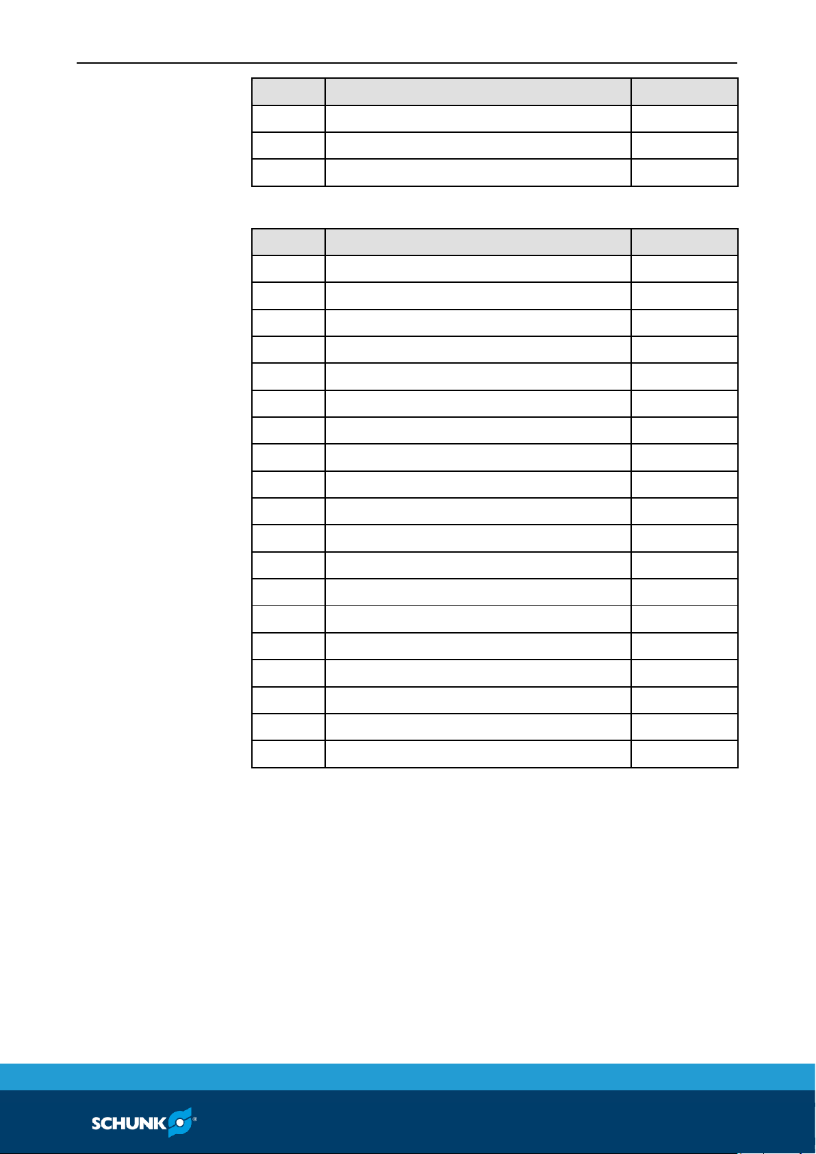
Item
Designation
Quantity
16*
O-ring Ø 6 x 1.5
2
20
Screw
6
21
Cover cap
6
NSE-M mini 90-V1
Item
Designation
Quantity
1
Base body
1 2 Cover
1 3 Drive ring
1 4 Drive piston
1 5 Setting piston
1 7 Clamping slide
3 8 Piston
2
9
Set-screw
3
10
Two-part pressure spring
3
11
Set-screw
2
12
Steel ball
1
13
Cylindrical pin
1
14
Bearing shell
3
15
Countersunk screw
3
16*
O-ring Ø 6 x 1.5
2
20
Screw
6
21
Cover cap
6
22
Fitting screw PSC mini
1
23
Cover plug mini
1
* Wear parts, replacement recommended during maintenance
Page 40
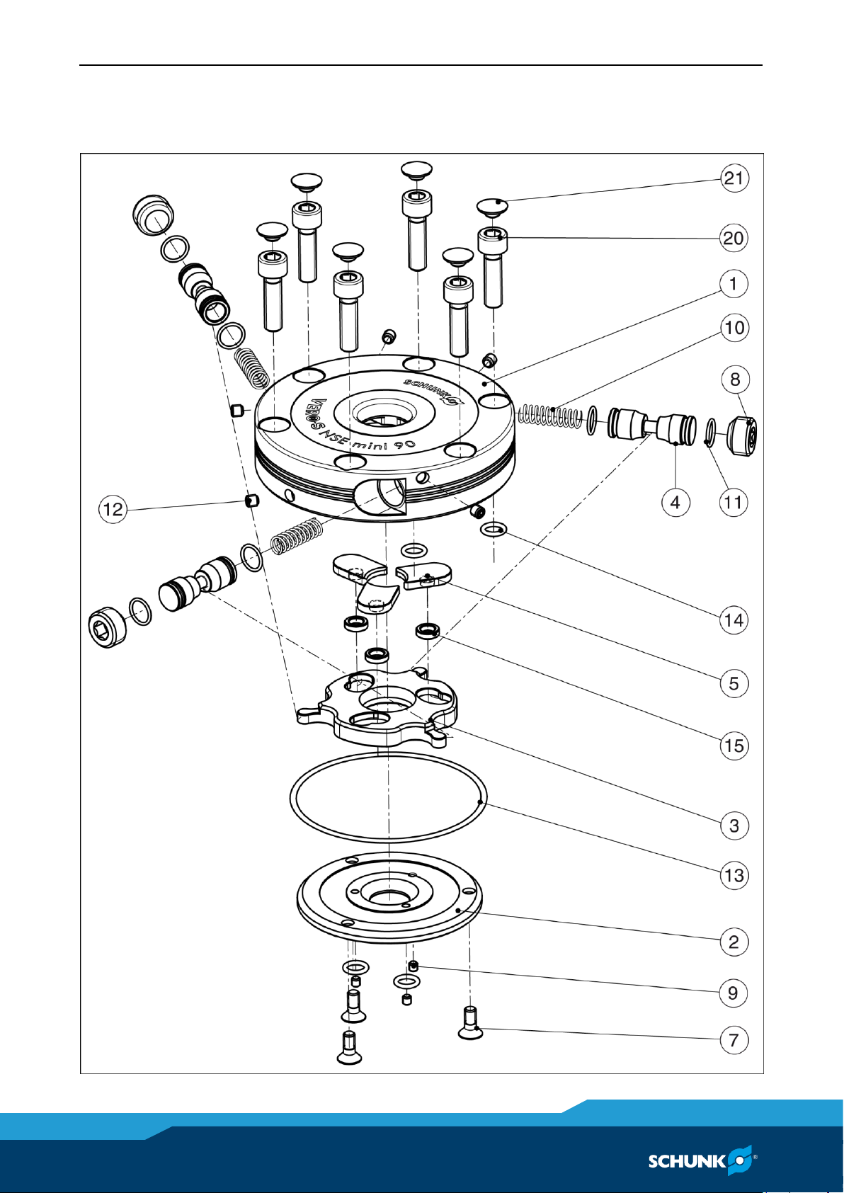
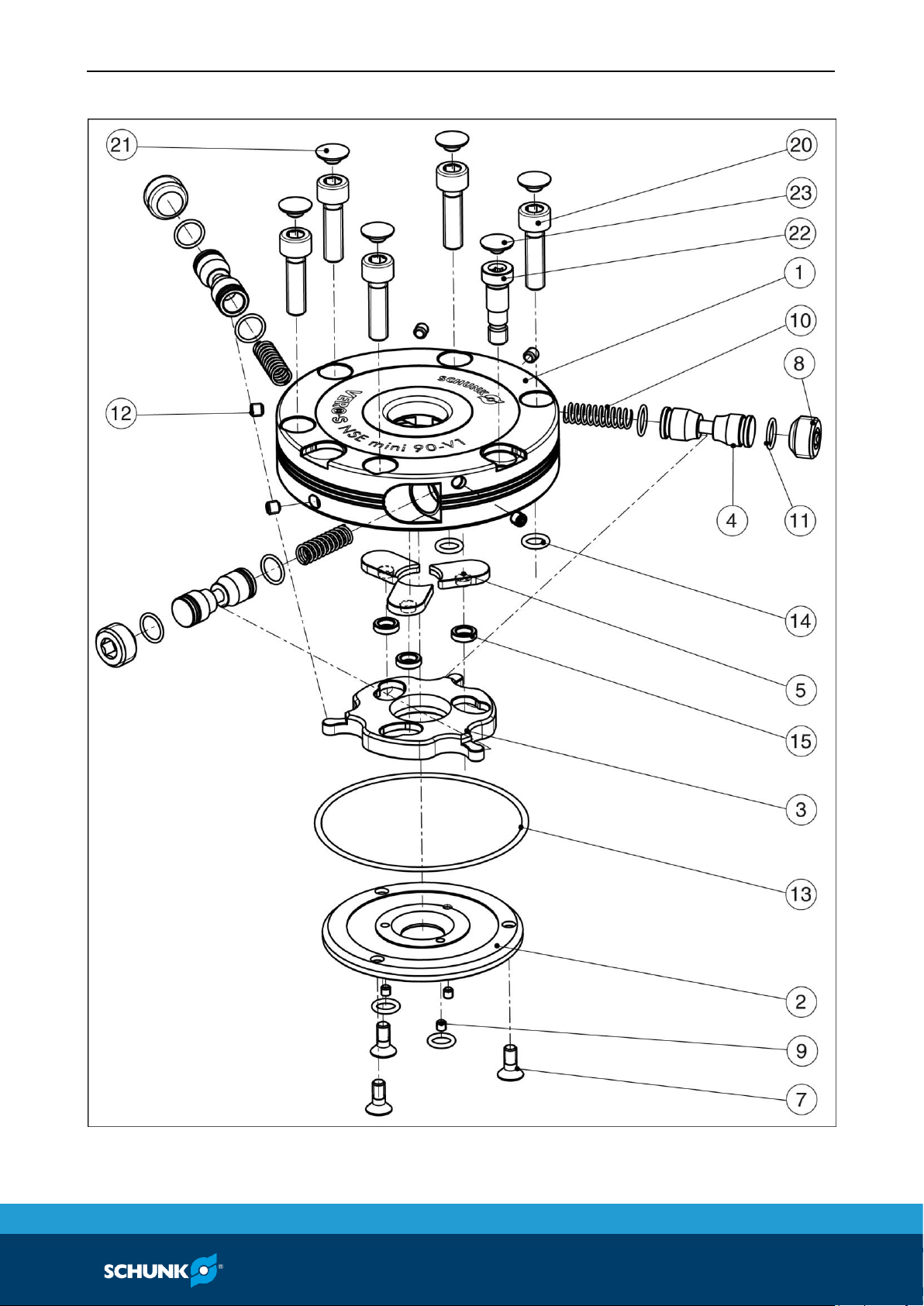
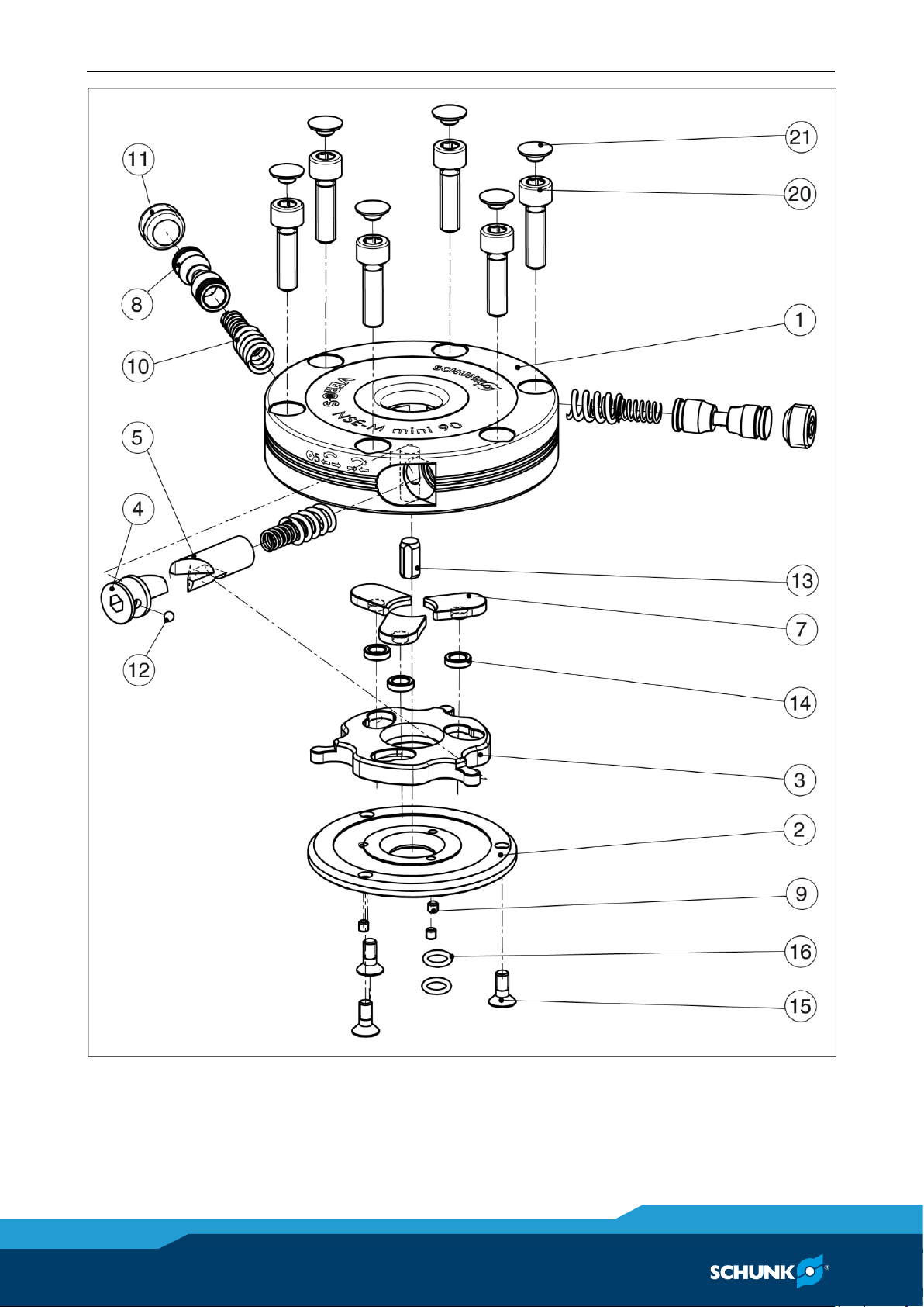
Drawings
40
02.00|NSE mini 90, NSE-M mini 90 |en
Drawings
NSE mini 90
11
Page 41
Drawings
02.00|NSE mini 90, NSE-M mini 90 |en
41
NSE mini 90-V1
NSE-M mini 90
Page 42
Drawings
42
02.00|NSE mini 90, NSE-M mini 90 |en
Page 43

Translation of original EC declaration of incorporation
02.00|NSE mini 90, NSE-M mini 90 |en
43
Translation of original EC declaration of
incorporation
in terms of the Directive 2006/42/EG, Annex II, Part 1.B of the European Parliament and of
the Council on machinery.
Manufacturer/
Distributor
H.-D. SCHUNK GmbH & Co.Spanntechnik KG
Lothringer Str. 23
D-88512Mengen
We hereby declare that on the date of the declaration the following partly completed
machine complied with all basic safety and health regulations found in the directive
2006/42/EC of the European Parliament and of the Council on machinery. The declaration
is rendered invalid if modifications are made to the product.
Product designation:
VERO-S quick-change pallet system
NSE mini, NSE mini-V1, NSE-M mini, NSE-M mini-V1
ID number
0435100; 0435105; 0435140; 0435145
The partly completed machinery may not be put into operation until it has been
confirmed that the machine into which the partly completed machinery is to be installed
complies with the provisions of the Machinery Directive (2006/42/EC).
Applied harmonized standards, especially:
DIN EN ISO
12100:2010
Safety of machinery - General principles for design -
Risk assessment and risk reduction
DIN EN ISO
4414:2010
Hydraulic fluid power – General rules and safety
requirements for pneumatic systems and their components
Other related technical standards and specifications:
VDI 3035:2008-05
Design of machine tools, production lines and
peripheral equipment for the use of cooling lubricants
The manufacturer agrees to forward on demand the special technical documents for the
partly completed machinery to national authorities.
The relevant technical documentation according to Annex VII, Part B, belonging to the
partly completed machinery, has been created.
Person authorized to compile the technical documentation:
Philipp Schräder, Address: refer to manufacturer's address
Mengen, January 2015
p.p. Philipp Schräder; Head of Engineering Design
12
 Loading...