

Page 1
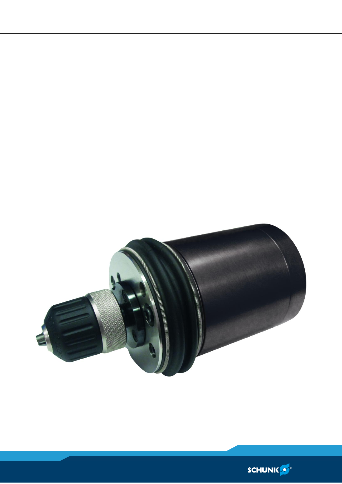
Original manual
Polishing Spindle
MFT
Assembly and operating manual
Superior Clamping and Gripping
Page 2

Imprint
2
01.00|MFT |en
Copyright:
This manual remains the copyrighted property of SCHUNK GmbH & Co. KG. It is solely
supplied to our customers and operators of our products and forms part of the product.
This documentation may not be duplicated or made accessible to third parties, in particular competitive companies,
without our prior permission.
Technical changes:
We reserve the right to make alterations for the purpose of technical improvement.
Document number: 0389545
Edition: 01.00 |15/01/2016|en
© SCHUNK GmbH & Co. KG
All rights reserved.
Dear customer,
congratulations on choosing a SCHUNK product. By choosing SCHUNK, you have opted for
the highest precision, top quality and best service.
You are going to increase the process reliability of your production and achieve best
machining results – to the customer's complete satisfaction.
SCHUNK products are inspiring.
Our detailed assembly and operation manual will support you.
Do you have further questions? You may contact us at any time – even after purchase.
Kindest Regards
Yours SCHUNK GmbH & Co. KG
Spann- und Greiftechnik
Bahnhofstr. 106 – 134
D-74348 Lauffen/Neckar
Tel. +49-7133-103-0
Fax +49-7133-103-2399
[email protected]
www.schunk.com
Imprint
Page 3

Table of contents
01.00|MFT |en
3
Table of contents
Glossary of Terms ..................................................................................................... 5
1
About this manual .................................................................................................... 6
1.1
Warnings ................................................................................................................... 6
1.2
Applicable documents .............................................................................................. 7
1.3
Variants ..................................................................................................................... 7
2
Basic safety notes .................................................................................................... 8
2.1
Intended use ............................................................................................................. 8
2.2
Not intended use ...................................................................................................... 8
2.3
Environmental and operating conditions ................................................................. 8
2.4
Product safety........................................................................................................... 9
2.4.1
Protective equipment ................................................................................... 9
2.4.2
Constructional changes ................................................................................. 9
2.5
Personnel qualification ............................................................................................. 9
2.6
The use personal protective equipment ................................................................ 10
2.7
Transportation and Protection during Transportation .......................................... 11
2.8
Safety Precautions .................................................................................................. 11
3
Warranty ................................................................................................................. 12
4
Scope of delivery ..................................................................................................... 13
5
Technical Specifications ........................................................................................... 14
6
Description and function ......................................................................................... 17
6.1
Description ............................................................................................................. 17
6.2
Spindle Operation and Media Selection ................................................................ 18
7
Assembly and Installation ........................................................................................ 19
7.1
Mechanical connection .......................................................................................... 19
7.2
Pneumatic Connection ........................................................................................... 19
7.3
Electrical Connections ............................................................................................ 22
7.4
Initial Operation...................................................................................................... 23
7.4.1
Media Considerations ................................................................................. 23
7.4.2
Tool Position and Programming ................................................................. 23
8
Maintenance and repair .......................................................................................... 25
8.1
Routine Operational Maintenance ......................................................................... 25
8.2
Media Replacement .............................................................................................. 25
8.3
Boot Replacement .................................................................................................. 26
8.4
Air Motor Replacement .......................................................................................... 27
8.5
Sensor Replacement ............................................................................................... 28
Page 4

Table of contents
4
01.00|MFT |en
8.5.1
Sensor for monitoring: Spindle extracted (Option -F) ................................ 29
8.5.2
Sensor for monitoring: Spindle retracted (Option -R) ................................ 30
8.5.3
Sensor for rotation speed: Tachometer sensor (Option -T) ....................... 30
8.6
Pneumatic -lines/-connections ............................................................................... 32
8.7
Lubrication of the polishing spindle ....................................................................... 32
8.8
Storage and Preventive Maintenance during Storage ........................................... 33
9
Troubleshooting ...................................................................................................... 34
9.1
Troubleshooting Matrix .......................................................................................... 34
10
Recommended Spare Parts ...................................................................................... 35
11
Drawings ................................................................................................................. 36
12
Translation of original declaration of incorporation ................................................. 40
Page 5

Glossary of Terms
01.00|MFT |en
5
Glossary of Terms
Adapter
Air Filter
Burr
Chuck
Compliance
Forward Sensor
Gearhead
Main Housing
Media
Rear Housing
Regulator
Retract Sensor
Solenoid Valve
Spindle
Tachometer Sensor
Vane Motor
Device for attaching the tool to robots
or work surfaces.
Device for removing contamination
from air supply lines. Typically refers to
removal of particulates.
Any unwanted, raised protrusion on
the workpiece.
Gripping device used to hold tools and
media to the spindle.
The ability of the spindle to passively
move in response to protrusions on or
deviations of the work piece.
Rear cover to the main housing. This
body includes a connection port for the
compliance air supply and feed-through
seals for optional electrical sensors.
Device used to set and control the supplied air pressure to lower acceptable
levels.
The retract sensor is an optional inductive proximity switch which is ON when
the spindle is in the fully retracted position indicating there is no further motion possible.
Electrically controlled device for
switching air supplies on and off.
The forward sensor is an inductive proximity switch which is ON when the spindle is in the fully extended position indicating there is no contact with the tool.
A gearbox responsible for reducing the
spindle speed of the air motor.
The main cylindrical body of the unit
which includes the mounting features.
Term referring to tools and/or abrasives held by the tool during the completion of a manufacturing process.
The rotating portion of the tool assembly.
The tachometer sensor is an optional inductive proximity switch which monitors
the rotation of a disk mounted behind
the chuck on the spindle. The sensor will
deliver two OFF pulses per spindle rotation. It is recommended that the tachometer sensor be utilized for process development but removed from the unit
when in a production environment.
Air motor that drives the tool spindle.
Page 6

About this manual
6
01.00|MFT |en
DANGER
Danger for persons.
Non-compliance will inevitably cause irreversible injury or death.
WARNING
Dangers for persons.
Ignoring a safety note like this can lead to irreversible injury and
even death.
CAUTION
Dangers for persons.
Non-observance can cause minor injuries.
NOTICE
Material damage
Information about avoiding material damage.
1
1.1
About this manual
This manual contains important information for a safe and appropriate use of the product.
This manual is an integral part of the product and must be kept accessible for the personnel at all times.
Before starting work, the personnel must have read and understood this operating manual. Prerequisite for safe working is the
observance of all safety instructions in this manual.
Illustrations in this manual are provided for basic understanding of
the product and may differ from the actual product design.
In addition to these instructions, the documents listed under
( 1.2, Page 7) are applicable.
Warnings
To make risks clear, the following signal words and symbols are
used for safety notes.
Page 7

About this manual
01.00|MFT |en
7
1.2
1.3
Applicable documents
• General terms of business *
• Catalog data sheet of the purchased product *
The documents marked with an asterisk (*) can be downloaded on
our homepage www.de.schunk.com.
Variants
This operating manual applies for the following variations
• Polishing Spindle-MFT
• Polishing Spindle-MFTNL
Page 8

Basic safety notes
8
01.00|MFT |en
2
2.1
2.2
2.3
Basic safety notes
Intended use
The Polishing Spindle MFT is intended to perform robotic and nonrobotic material finishing operations.
The product is intended for installation in a machine/system. The
requirements of the applicable guidelines must be observed and
complied with.
The product may be used only in the context of its defined applica-
tion parameters ( 5, Page 14).
The product is designed for industrial use.
To use this product as intended, it is also essential to observe the
technical data and installation and operation notes in this manual.
Not intended use
It is not intended use if the product is used, for example, as a
pressing tool, stamping tool, lifting gear, guide for tools, cutting
tool, clamping device or a drilling tool.
• Any utilization that exceeds or differs from the appropriate use
is regarded as misuse.
Environmental and operating conditions
Requirements for the ambient and operating conditions
Due to incorrect ambient and operating conditions, dangers may
arise from the product, which can cause serious injury and substantial property damage.
• Make sure that the product is used only in the context of its de-
fined application parameters, ( 5, Page 14).
• The Polishing Spindle MFTshould only be used in an automated
cell/chamber.
• The work cell must be secured by means of barriers to prohibit
personnel from entering the cell. A lockable door should be included as a part of the barrier in order to facilitate access to the
cell for authorized personnel only. The barrier could consist
partly or fully of Plexiglas to facilitate observation of the manufacturing process.
Page 9

Basic safety notes
01.00|MFT |en
9
• Be aware of high sound levels. While the Polishing Spindle MFT
NOTE
More information is contained in the relevant chapters.
2.4
2.4.1
2.4.2
2.5
air motor is not loud, the cutting action associated with many
processes frequently is. Always use hearing protection while
working in the neighborhood of the production cell.
Product safety
Dangers arise from the product, if:
• the product is not used in accordance with its intended purpose.
• the product is not installed or maintained properly.
• the safety and installation notes are not observed.
Avoid any manner of working that may interfere with the function
and operational safety of the product.
Protective equipment
Wear protective equipment.
Provide protective equipment per EC Machinery Directive.
Constructional changes
Making constructional changes
Attachements and modifications, constructional changes and subsequent work, e.g. additional threads, drill holes and safety devices, can
compromise the operation and safety or damage the product.
• Constructional changes may be only done with permission from
SCHUNK.
Personnel qualification
Inadequate qualifications of the personnel
If the personnel working with the product is not sufficiently qualified,
the result may be serious injuries and significant property damage.
• All work may be only performed by qualified personnel.
• Before working with the product, the personnel must have read
and understood the complete assembly and operating manual.
• Observe the national safety regulations and rules and general
safety instructions.
Page 10

Basic safety notes
10
01.00|MFT |en
The following personal qualifications are necessary for the various
Trained electrician
Pneumatics specialist
Hydraulic specialist
Qualified personnel
Instructed person
Service personnel of
the manufacturer
2.6
activities related to the product:
Due to their technical training, knowledge and experience, trained
electrician are able to work on electrical systems, recognize and
avoid possible dangers and know the relevant standards and regulations.
Pneumatics specialists have been trained for this particular area of
responsibility and know the relevant standards and regulations.
Hydraulic specialists have been trained for this particular area of
responsibility and knows the relevant standards and regulations.
Due to their technical training, knowledge and experience, qualified personnel is able to perform the delegated tasks, recognize
and avoid possible dangers and knows the relevant standards and
regulations.
Instructed persons were instructed by the operator about the delegated tasks and possible dangers due to improper behaviour.
Due to their technical training, knowledge and experience, service
personnel of the manufacturer is able to perform the delegated
tasks and to recognize and avoid possible dangers.
The use personal protective equipment
Using personal protective equipment
If no personal protective gear is worn while working with the product, the safety and health of the personnel may be compromised.
• Observe the health and safety regulations and wear the necessary personal protective equipment while working with the
product.
• Observe the applicable safety accident prevention regulations.
• Use protective gloves for sharp edges, sharp corners and rough
surfaces.
• Use protective gloves for hot surfaces.
• Use protective gloves and googles when handling hazardous
substances.
• Wear tight protective clothing for moving components.
Page 11

Basic safety notes
01.00|MFT |en
11
Transportation and Protection during Transportation
2.7
2.8
The MFT is packaged in a crate designed to secure and protect it
during transportation. Always use the crate when transporting the
MFT in order to minimize the risk of damage.
Safety Precautions
• Never use or start the MFT without first reading and understanding the operating procedures described in this manual.
• Make sure that the MFT is mounted as described in this manual.
• Never use the MFT for any purposes or in any ways not explicitly described in this manual.
• Make sure that the pneumatic control equipment is connected
as described.
• Only original spare parts supplied by SCHUNK must be used.
• Install a barrier to prohibit people from approaching the MFT
while in operation.
• Never be present near the MFT while it is started or running. If
it is necessary to approach the MFTwhile in motion, stand behind appropriate Plexiglas windows.
• Be aware of rotating parts.
• Abrasive media must be rated for at least 5,600 1/min.
• Use eye protection.
• Be aware of high sound levels during cutting. Always use hearing protection while working in the neighborhood of the MFT.
• During system or tool maintenance, make sure the MFT and
equipment are stopped before entering the cell. Never be
present in the cell when the tool is running when installing and
testing.
Page 12

Warranty
12
01.00|MFT |en
3
Warranty
The warranty of the Polishing Spindle MFT is valid for 24 months.
This does not apply to the air motor.
The air motor is warranted for a period of 2000 hours or one year
of operation from date of delivery from the production facility,
whichever occurs first.
Parts touching the work piece and wear parts are not part of the
warranty.
Page 13

Scope of delivery
01.00|MFT |en
13
4
Scope of delivery
The scope of delivery includes
• Polishing Spindle MFT in the ordered model
Page 14

Technical Specifications
14
01.00|MFT |en
Operating temperature [°C]
5 - 35
Storage Temperature [°C]
0 - 45
Pressure medium
MFT-390:
clean, dry, filtered, lubricated air.
MFT-390-NL:
clean, dry, filtered, not lubricated air.
The use of a coalescing filter and
filter elements rated 5 micron or
better is recommended.
Air consumtion [l/s] at 6.2 bar
9
Motor
Air motor, vane type
Idle Speed [1/min]
5,600
Working Speed
(max. power) [1/min]
2,600
Power at 2,600 1/min [W]
390
Continuous torque (max. power)
[Nm]
1.4 Nm
Starting torque (starting/stall)
2.7 Nm
Weight total (w/o adapter)
3.3 kg
Compensation axial (max.) [mm]
15
7–8 recommended
Compliance force @ supply
pressure of 0.34–4.1 bar [N]
14–74
Sspindle air pressure (max.)
[bar]
6.2
Air consumption (max.) [l/s]
approximately 9
Oil consumption
(not valid for MFT 390-NL)
Approx. 3–4 drops of oil per
minute (1 drop = 15mm3) by oil
fog at max. air consumption
Ffast Tightening Chuck size
3/8 "
Abrasive media
Customer-supplied
Sound Pressure Level [dBA]
No-Load at a Distance of 1.5
meters from Tool
< 75 *
5
Technical Specifications
Main specifications for the axially compliant tool:
Page 15
Technical Specifications
01.00|MFT |en
15
*
Because the working environment is unknown, it is impossible
to predict the noise that will occur during an operation. The
tool may also excite resonant frequencies on equipment to
which it is mounted creating higher sound pressure levels than
the unit by itself.
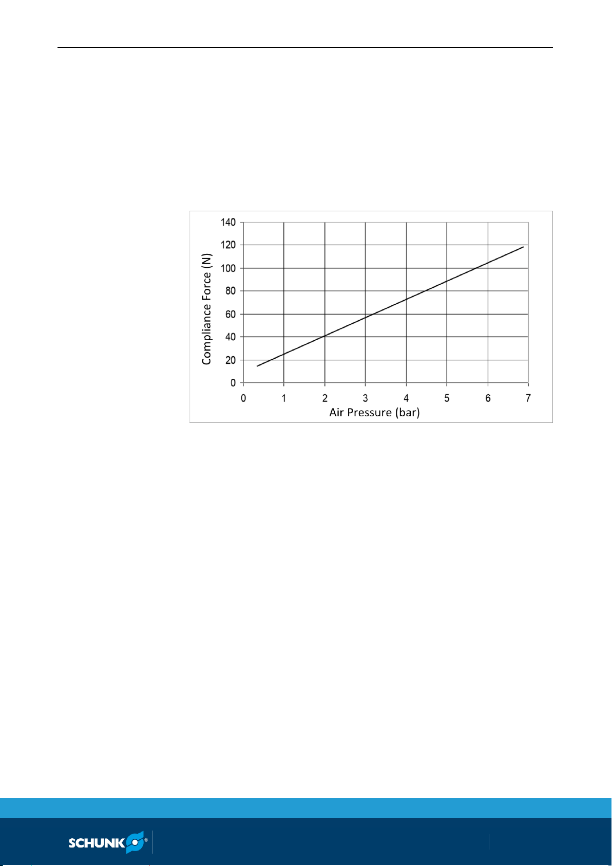
The following charts show measured forces relative to applied
compliance air pressure. Measurements may vary from one product to another, and should only be treated as nominal.
Horizontal Compliance Force Curves
The force characteristics shown graphically above are for horizontal, rigidly-mounted installations. The weight of the motor, chuck,
and abrasive media must be added to this if the motor is mounted
vertically with the spindle down or subtracted with the spindle
pointed up. Units mounted at angles between horizontal and vertical provide a compliance force that must be calculated based on
the specific mounting geometry or orientation.
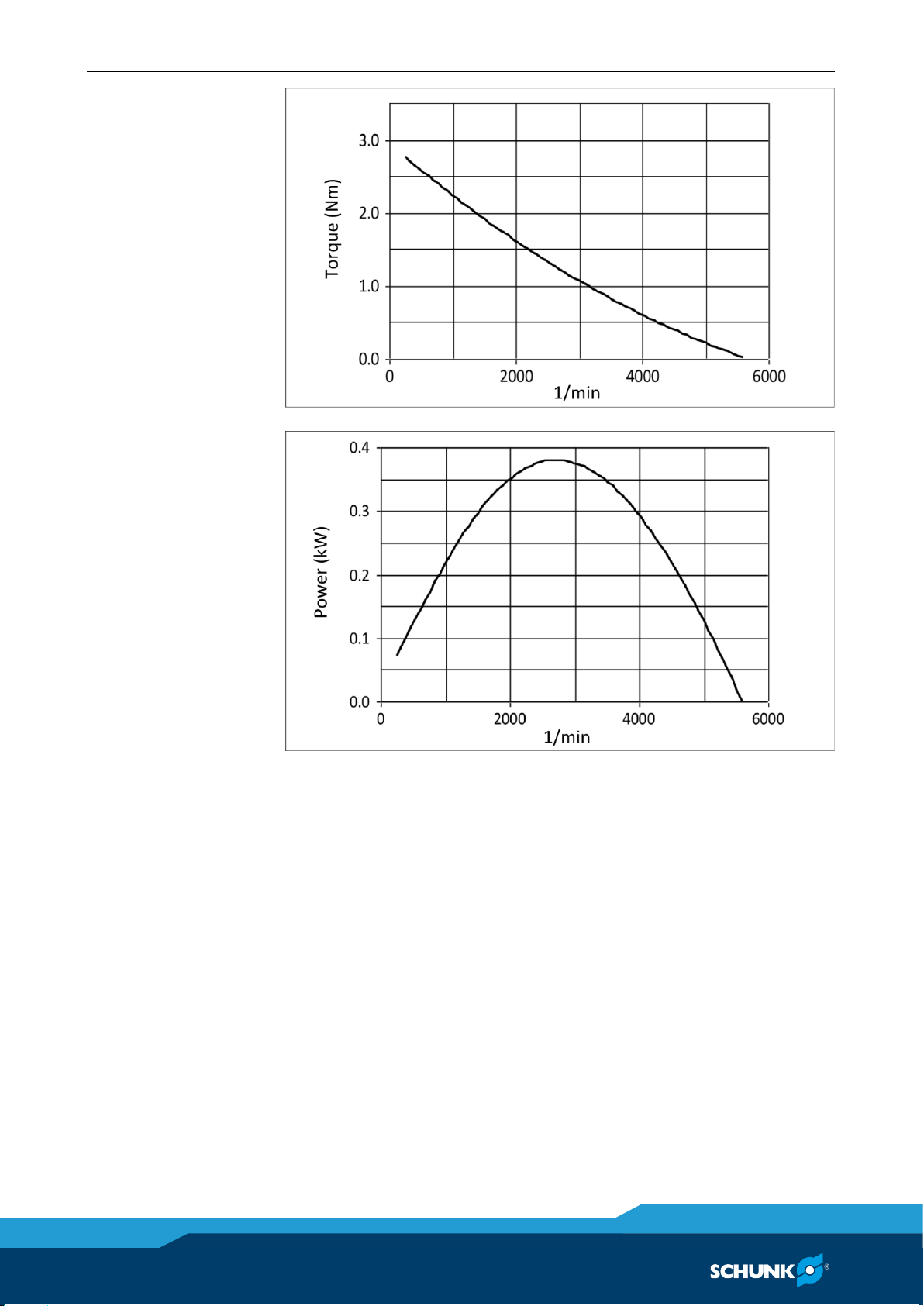
The air motor operating speed will change according to load applied to it developing the power required for the specific task being attempted. The idle speed of the motor will be its maximum as
no load is applied. This will drop to a lower operating speed where
it will develop the maximum torque. If the torque required exceeds the maximum available, the motor will stall.
Page 16
Technical Specifications
16
01.00|MFT |en
Motor Torque Curves
Motor Power Curves
Page 17

Description and function
01.00|MFT |en
17
NOTICE
• Never use the MFT for purposes other than automated
processes.
• Never use the MFT as a hand-held machine.
NOTE
Never use the MFT in a manner to produce radial loads. Avoid using the MFT for countersinking or drilling.
6
6.1
Description and function
Description
While the Polishing Spindle MFT provides axial travel, it is not designed to eliminate tool chatter which will be experienced in full
contact operations, such as countersinking. Rigid tools, such as
milling machines, are required for such applications. It may be
dangerous to operate the MFT for these purposes. If a failure occurs due to forces caused by improper use, hazardous situations
for both personnel and equipment could be created.
The Polishing Spindle MFT is not designed to support radial loads.
The use of radial media (wheel brushes and sanding drums) in the
unit is discouraged as this will lead to binding in the linear slides
preventing axial motion.
Reduce the feed rate when the work piece and the tool are making
initial contact. Making the contact movement between the tool
and the work piece too fast may in some situations result in a collision. Collisions may create hazardous situations for both personnel
and equipment.
When performing maintenance, always remember to tighten all
the fasteners. When replacing media always secure it correctly and
insure that the chuck is tightened ( 8.1, Page 25).
The air motor of the Polishing Spindle MFT is equipped with an
integral speed reduction gearbox. The life of this gearbox will be
reduced if the media extends a long distance from the tip of the
spindle. Whenever possible, select media and mounting adapters
for media that are short and position the work as close to the Polishing Spindle MFT as possible.
Page 18

Description and function
18
01.00|MFT |en
6.2
Spindle Operation and Media Selection
When used with flexible abrasive media, the Polishing Spindle MFT
will perform best when the rotating media approaches the burr in
a direction that will fold the burr back on itself. This will allow the
media to remove material rapidly without excessive force and
without the creation of a secondary burr. This will decrease the
cycle time for the operation while extending the life of the tool
and the consumable media. The MFT spindle rotates clockwise
when viewed from behind.
The selection of such media is highly dependent upon the work
piece material and geometry, and the amount of material to be
removed. It is not practical to present all the possibilities in this
document.
Page 19

Assembly and Installation
01.00|MFT |en
19
7
7.1
7.2
Notes on compressed
air supply
Assembly and Installation
Mechanical connection
The tool is designed for side mounting.
SCHUNK offers a side interface plate kit for bench mounting.
The tool must be rigidly mounted prior to use.
Under no circumstances should the unit be used for manual/hand
operations.
Pneumatic Connection
Air line fittings supplying the Polishing Spindle MFT should be installed with care using a minimum of tape or liquid sealant.
To prevent contaminant damage to the air motor, all air lines should
be blown down to remove debris prior to connection of the MFT.
Water damage of the air motor or damage associated with debris
in the air lines is not covered under warranty.
MFT-390
Once mounted, the Polishing Spindle MFT should be supplied with
clean, lubricated, filtered air.
MFT-390-NL
Once mounted, the Polishing Spindle MFT should be supplied with
dry, not lubricated air.
Page 20
Assembly and Installation
20
01.00|MFT |en
Connection
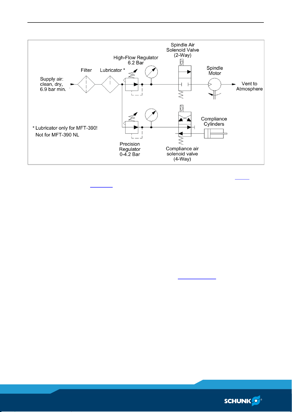
Connect the Polishing Spindle MFT as shown in the following figure.
Pneumatic Connections
The air supply should be dry, air filtered, and lubricated ( 5,
Page 14).
A high-flow air pressure control regulator is required to supply the
spindle motor at 6.2 bar. A second, precision, self-relieving regulator will supply air for the compliance or centering force.
The compliance force is applied axially and is adjusted until the desired finishing result is achieved. The robot traversing speed will
also be adjusted to achieve the desired finish.
Conventional, customer-supplied, pneumatic components are
used to control the air supply to the tool. SCHUNK recommends
that the user install a high-flow pneumatic pressure regulator and
a high-flow valve to properly supply a stable air supply of 6.2 bar
to the spindle motor. See Section ( 5, Page 14) for the maximum
flow requirements.) While the spindle motor can be operated below 6.2 bar, it will not develop full power or speed. Very little airflow is required for the compliance mechanism.
The air supply solenoid valve must be controlled through robot or
controller.
Page 21

Assembly and Installation
01.00|MFT |en
21
NOTICE
Pneumatic components used for the motor drive circuit must be
capable of meeting the air consumption requirements ( 5,
Page 14). Poor performance will result if the correct components
are not used. Lubricators must be located as close to the unit as
possible with performance rapidly deteriorating when the distance exceeds 5 meters.
Function
Connection Type
Pressure
Motor Inlet
G 1/4"
6.2 bar
Compliance (Axial)
Force
G 1/8"
0.34–4.1 bar (Maximum)
Exhaust
G 1/4" (High-flow
Muffler Supplied)
Not Applicable
The tool must be plumbed using flexible tubing. The inside diameter of the tubing should be as large as practical to minimize pressure drop to the spindle motor [10mm minimum].
The air motor is quiet and vents air to the environment through
the supplied high-flow muffler at the rear of the unit. The customer may choose to replace the muffler with tubing to carry exhaust
away from the work area. Such tubing must be as large and flexible
as possible to minimize pressure drops and allow unrestricted axial
motion respectively. To reduce the sound level in neighboring working areas, a customer-supplied barrier surrounding the installation
may be installed (Plexiglas or Lexan is preferred ( 5, Page 14).
The compliance force air supply pressure regulator should be adjusted between 0.34–4.1 bar. When testing for the proper contact
force, start with a very low pressure and increase slowly until the
desired process result is achieved.
Page 22
Assembly and Installation
22
01.00|MFT |en
Electrical Connections
7.3
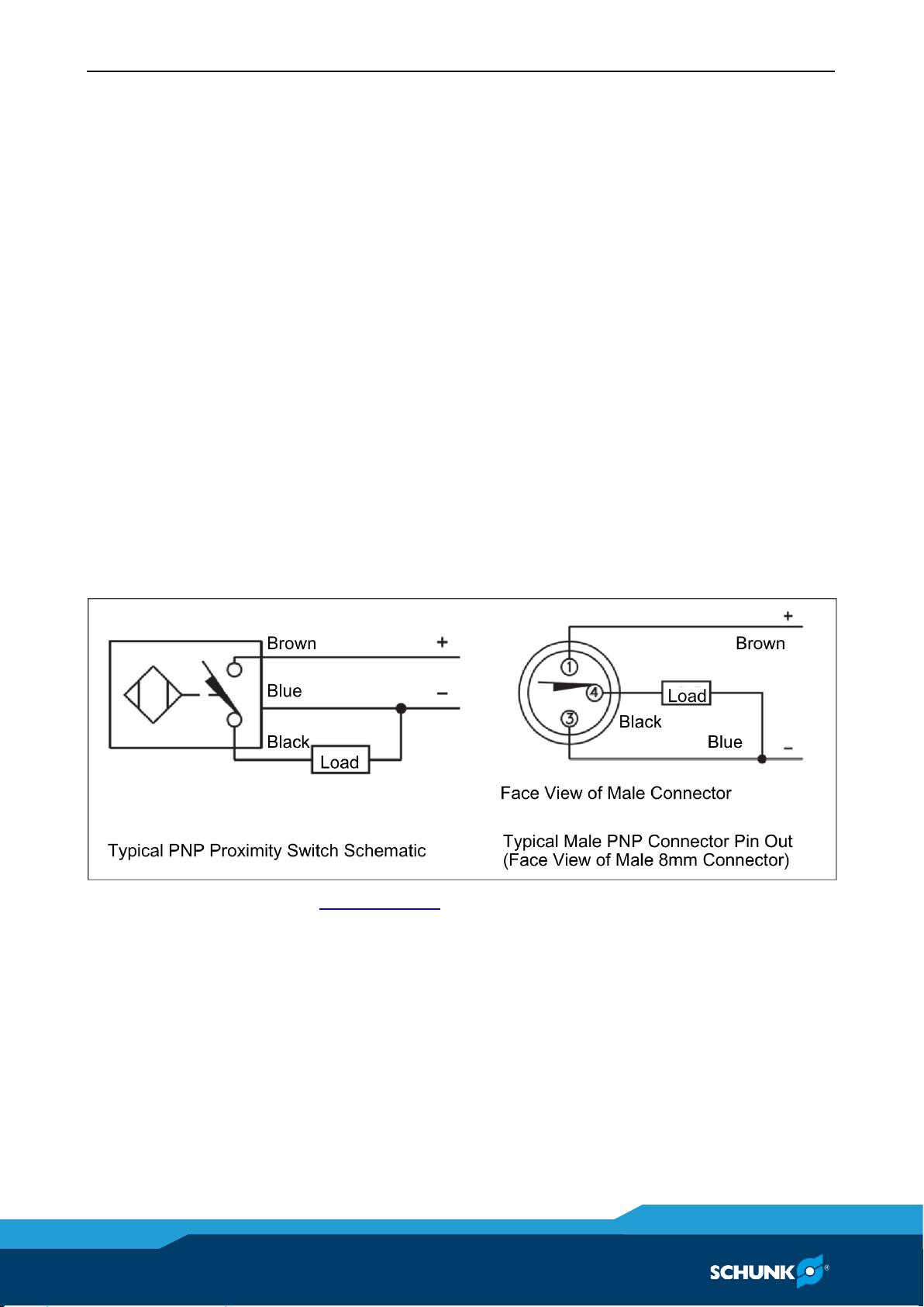
The Polishing Spindle MFT tool can be equipped with up to three
sensors to monitor spindle position and speed. These include the
Forward, Retract, and Tachometer sensors. Each sensor is a PNP
(sourcing) type proximity switch using three wire electrical hook-up.
The Forward and Tachometer sensors are a standard 8mm
threaded body 3-pin type. Unterminated cables are connected to
these sensors and exit the rear of the deburring tool. The Retract
sensor is a flat proximity switch whose short cable is terminated
with a male threaded 8mm connector. This connection may be extended using any industry standard 8 mm 3-pin cable.
The electrical connections for 3-pin proximity sensors are colorcoded and adhere to industry-standards. The blue sensor wires are
connected to 0V and the brown wires are connected to a positive
voltage source between 10V and 30VDC. With the PNP sensors
used on Polishing Spindle MFT, the black wire is the output signal,
which will go "high" when the switch closes (turns on). Thus, the
sensor "sources" power to the load or monitoring circuit.
See ( 8, Page 25) of this manual for more information on setting
and using these sensors.
Page 23

Assembly and Installation
01.00|MFT |en
23
Initial Operation
7.4
7.4.1
7.4.2
These operating instructions are intended to help system integrators program, start up, and complete an installation containing an
axially compliant tool. The system integrator should be familiar
with the task in general and should have extensive knowledge of
programming and automation.
Important Note Regarding Operation:
The air motor is supported by two guide rods attached to the front
plate of the deburring tool. To prevent binding of the compliance,
one of these guide rods is rigidly attached to the front plate. The
second guide rod and the compliance piston rods are free to float
in the front plate. This allows the motor assembly to achieve free
compliant motion while resisting the motor’s torque.
DO NOT attempt to change the floating nature of the rods by adding washers or additional thread locker. These actions will prevent
the rods from floating, which will result in binding of the tool’s
compliance.
Media Considerations
For instructions on how to replace the media, see ( 8.1, Page 25)
In most applications, no cooling or lubrication of the part or tool is
necessary nor is it desirable. For some materials and situations,
the addition of coolants or compressed air may aid the cutting
process. Any application of coolant must be exercised with care to
prevent fluids from entering the tool or its chuck.
Select media and media holders that position the work piece as
close to the Polishing Spindle MFT as possible.
Tool Position and Programming
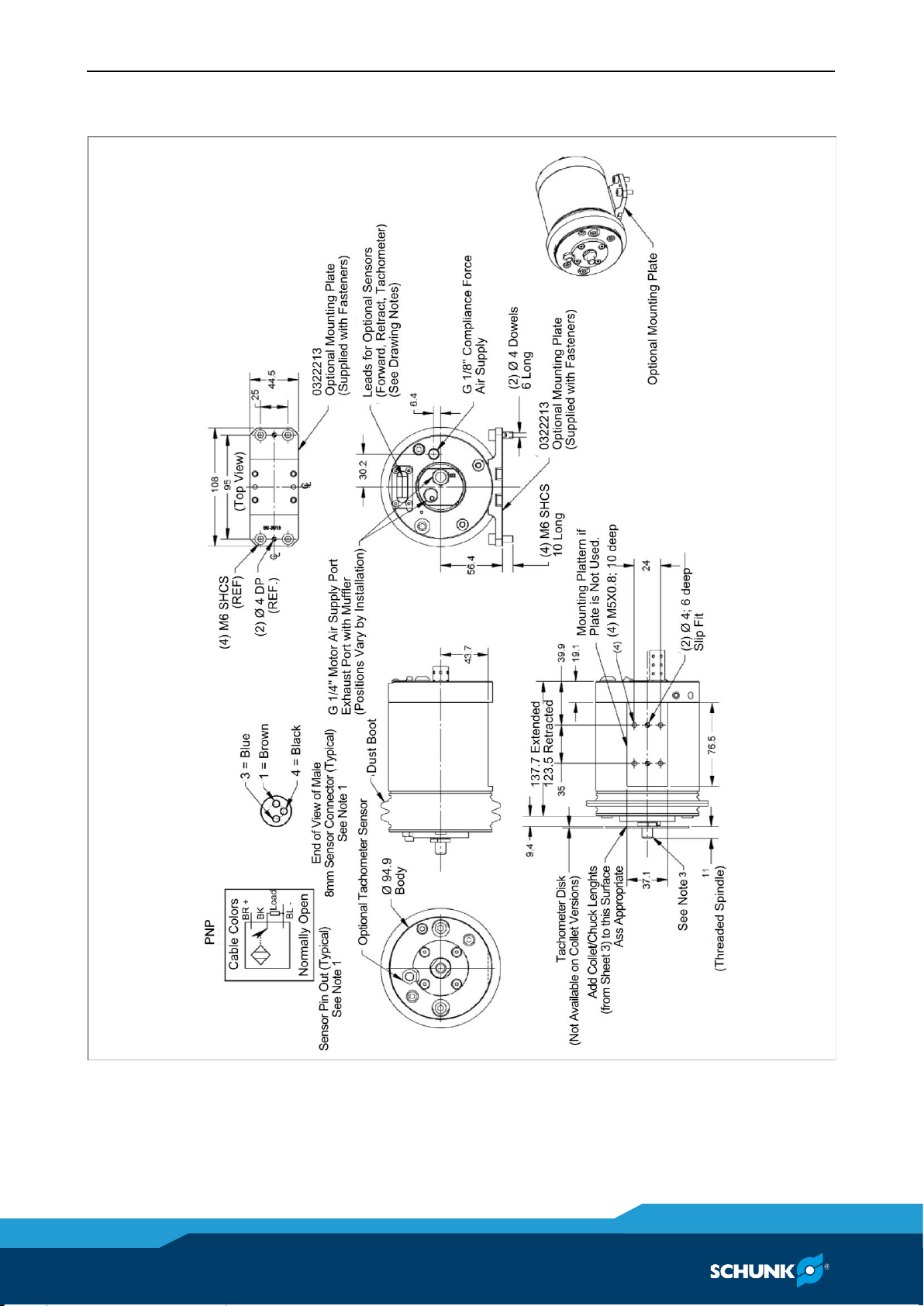
The Polishing Spindle MFT dimensions are provided in the draw-
ings in ( 11, Page 36). The MFT provides axial compliance and
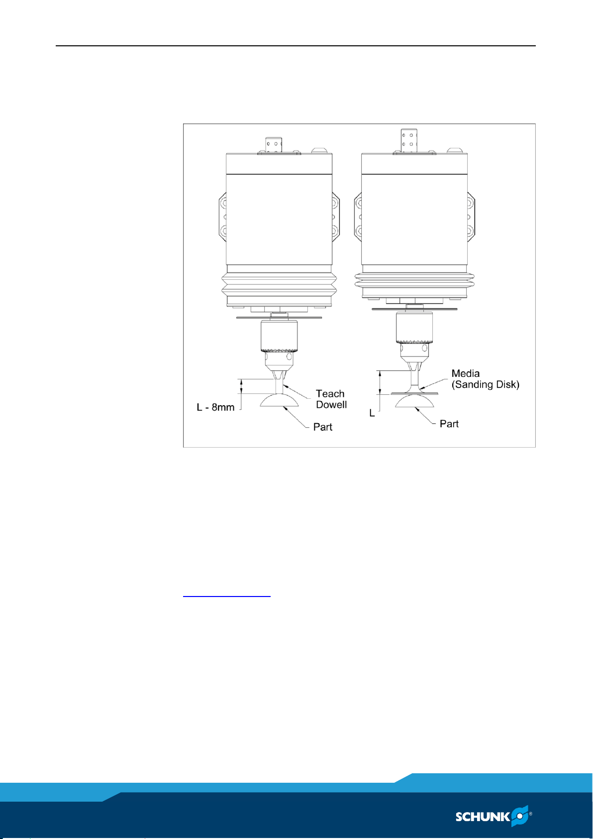
performs best when the spindle is displaced through approximately one-half of its allowable travel (approximately 8 mm). The tool
spindle must never be running while programming a machining
center. During teaching, the compliance air must be on and supplied near 1.4 bar.
Page 24
Assembly and Installation
24
01.00|MFT |en
A simple programming method is to replace the desired media
with a dowel pin which projects 8 mm less from the tool's chuck
than the production media that will be used. The tip of this dowel can
then be used to contact the part when teaching the robot path.
The short, teach dowel pin with the tool spindle fully extended
(left in Figure) will simulate the position of the spindle deflected
8mm when the actual media/tool is installed (right in Figure).
When running the program the first time, observe the path with
the compliance air supply turned down to approximately 1.4 bar.
Verify that at operational speed the media is deflected but contacts the work surface. Once the path has been confirmed, the
compliance force of the media should be adjusted as described in
( 7.2, Page 19) in order to achieve the desired finish.
Page 25

Maintenance and repair
01.00|MFT |en
25
8
8.1
8.2
Maintenance and repair
Important Note Regarding Operation:
The air motor is supported by two guide rods attached to the front
plate of the deburring tool. To prevent binding of the compliance,
one of these guide rods is rigidly attached to the front plate. The
second guide rod and the compliance piston rods are free to float
in the front plate. This allows the motor assembly to achieve free
compliant motion while resisting the motor’s torque.
DO NOT attempt to change the floating nature of the rods by adding washers or additional thread locker. These actions will prevent
the rods from floating, which will result in binding of the tool’s
compliance.
Routine Operational Maintenance
The tool utilizes a vane-type air motor with integral speed reduction gearbox. When subjected to normal use, the Polishing Spindle
MFT will provide many hours of operation before service or repair
is necessary. When subjected to high shock loading or periods of
continuous service without interruption, the unit will require service or repair earlier. While simple in design, there are few userserviceable parts in the assembly. The user is encouraged to return
the unit to SCHUNK for service. The following information is provided
to assist the user when they choose to service the unit in the field.
For all service, it is recommended that the air supply (before the
solenoid valves) be disconnected. Drain any trapped air pressure in
the lines. It is suggested that the air supply be "locked out" to prevent accidental operation of the spindle. During maintenance op-
erations, refer to drawings in ( 11, Page 36).
Media Replacement
The Polishing Spindle MFT unit ships with a simple drill chuck to
hold customer-supplied media. A standard chuck key is used to
loosen and tighten the chuck. When tightening the chuck, insert
and turn the key into each of the three holes around the chuck's
perimeter.
Page 26

Maintenance and repair
26
01.00|MFT |en
Boot Replacement
WARNING
This boot is not provided as a safety device
• Under no circumstances should the user operate the Polishing
Spindle without the boot.
• The user should never have their hands on or near the Polishing Spindle when in operation.
8.3
Remove
Install
The tool is equipped with a simple boot between the moving motor mounting plate and the main housing. This boot is provided to
minimize contamination of the guide and piston rods allowing free
axial motion.
1 Discharge any pressure in the air lines to the tool's spindle and
compliance connections.
2 Use a suitable pick or small ball-end hex wrench to lift and re-
move the o-ring securing the boot to the front plate of the unit.
3 Similarly remove the o-ring securing the boot to the main
housing.
4 Use the pick to lift the boot as necessary and slide it forward
off the spindle end of the tool.
1 Slip the first o-ring up and over the boss of the main housing,
temporarily leaving the o-ring on the main housing.
2 Slip the boot over the moving motor mount plate and onto the
main housing.
3 Position the boot so its locking surfaces engage the grooved
boss on both the moving plate and the main housing.
4 Refit both o-rings to secure the boot.
Page 27

Maintenance and repair
01.00|MFT |en
27
8.4
Remove
Air Motor Replacement
The air motor oft the variant MFT-390 must be operated using lubricated air or it will fail and require replacement. The air motor of the
variant MFT-390-NL should not be operated with lubricated air.
The motor includes a gearbox (gearhead) to lower the spindle
speed. Maintenance of either the motor or the gearbox requires
the motor be removed from the tool.
MFT units with defective motors should be returned to SCHUNK
during the warranty period. Should the customer wish to replace
the motor after the warranty period, the following steps must be
performed.
1 Discharge any pressure in the air lines to the tool's spindle and
compliance connections.
2 Disconnect the flexible tubing supplying the air motor and
compliance.
3 Disconnect any air lines connected to the motor's exhaust port
in place of the muffler.
4 Thread G 1/4" straight fittings or pipe nipples into the motor's
supply and exhaust ports to use as handles during the removal
sequence.
5 Use the 15 mm open-end wrench to hold the spindle nut be-
hind the chuck.
6 Insert the chuck key into the chuck. While holding the 15 mm
wrench securely, unscrew the chuck counterclockwise using
the chuck key as a lever.
7 With the chuck removed, hold the spindle threads with fingers
and remove the 15 mm nut previously held by the open end
wrench.
8 Use a hex wrench to loosen the four flat-head screws securing
the seal plate to the moving motor mount plate at the front of
the tool, thus freeing the air motor.
9 At the rear of the unit, grasp the fittings/nipples installed pre-
viously in the rear of the air motor and use them to rotate the
motor CLOCKWISE from the rear. NOTICE! The motor mount
uses left-hand threads, rotate CLOCKWISE to remove.
This will unscrew the motor from the front plate of the tool.
Page 28

Maintenance and repair
28
01.00|MFT |en
Install
8.5
1 Reassembly is the reversal of these steps noting the following
important steps.
2 Fit the seal plate to the moving motor mount plate tightening
the flat-head screws until they bottom out.
3 Back the flat-head screws out one-half (1/2) turn.
4 Thread the motor into the front plate
Remembering that the motor mount has left-hand threads and
must be turned counterclockwise (from the rear) to tighten.
5 When the motor bottoms out against the seal plate, return to
the flat-head screws on the seal plate and tighten them securely.
6 Apply a thin film of grease to the shoulder of the 15 mm nut
that goes behind the chuck
7 Thread the 15 mm nut it onto the motor shaft until it bottoms out.
8 Thread the chuck onto the spindle until it bottoms out on the
15 mm nut.
9 As during removal, insert the chuck key into the chuck and use
it as a lever to tighten the chuck against the 15 mm nut held
by the open end wrench.
10 Reinstall the desired air supply fittings as appropriate.
Sensor Replacement
The Polishing Spindle MFT may be outfitted with up to three proximity sensors. These sensors may be monitored by the customer to
determine the following information.
1 Monitoring –F: Forward Sensor. This sensor is included on all
units. It is ON when the spindle is fully forward.
2 Monitoring –R: Retract Sensor. This sensor is ON when the
spindle is fully Retracted.
3 Monitoring –T: Tachometer. This sensor delivers two OFF
pulses for every spindle rotation.
These sensors for monitoring R and T can be added in the field.
Page 29

Maintenance and repair
01.00|MFT |en
29
Sensor for monitoring: Spindle extracted (Option-F)
8.5.1
Remove
Install
The sensor is mounted inside the housing of the Polishing Spindle.
When the spindle is fully extracted the sensor will turn on. The
spindle must be displaced approximately 1mm to the rear before
the sensor will turn off. This may be utilized to insure that the media is in contact with the part to be deburred.
1 Discharge any pressure in the air lines to the tool's spindle and
compliance connections.
2 Remove the three socket head screws holding the rear hous-
ing to the front housing.
3 Remove the rear housing and observe the nickel plated cylin-
drical sensor mounted in the plastic block.
4 Remove the screw securing the plastic block to the housing
and remove the sensor, pulling its lead through the rubber
seal of the rear housing.
1 Reassembly is the reversal of these steps noting the following
important steps.
2 Fit the plastic block to the housing and push the spindle fully
forward.
3 Adjust the clearance between the face of the nickel plated
sensor and the head of the socket head screw until the radial
gap is approximately 1 mm.
4 Tighten the screw securing the block to the housing.
5 Pass the sensor wire out of the rear housing seal and refit the
rear housing to the main housing of the tool. Insure that all o-
ring seals are in place before securing the screws.
6 Connect the sensor wires to an appropriate power supply.
(24V DC with blue = 0V, brown = +24V, and black = output).
7 Remove the stainless button head screw from the rear hous-
ing and reach through the opening with the appropriate sized
hex wrench to turn the adjusting screw.
8 Push the motor mounting plate all the way forward.
9 With the spindle pushed all the way forward, turn the target
socket head screw counter clockwise until the sensor just
turns OFF.
10 Turn the target screw one complete turn clockwise.
11 Refit the stainless steel button head screw.
Page 30

Maintenance and repair
30
01.00|MFT |en
NOTE
The tachometer option is for process development. The thin target
disk may be damaged in a production environment. Once process
development is complete, the customer is advised to remove the
target disk from the spindle or to insure that nothing can accidentally strike the target.
8.5.2
8.5.3
Sensor for monitoring: Spindle retracted (Option-R)
The sensor is mounted to the rear housing inside the tool. When
the spindle is within approximately 1.5mm of being fully retracted
the sensor will turn on. This may be utilized to indicate when excessive brush force is being applied (i.e., the brush has been
pushed back so far and so hard that the end of compliance travel
has been reached).
To remove, and install the sensor perform the following steps
(there is no adjustment).
1 Discharge any pressure in the air lines to the tool's spindle and
compliance connections
2 Remove the three socket head screws holding the rear hous-
ing to the front housing.
3 Locate the flat sensor secured to the rear housing using a sin-
gle flat-head screw.
4 Remove the flat-head screw and pass the sensor and wire
through the slot and rubber seal on the rear housing.
5 Reassembly is the reversal of these steps.
Sensor for rotation speed: Tachometer sensor (Option -T)
The tachometer sensor is an optional speed sensing system that allows the user to monitor the rotating speed of the spindle. A target disk is sandwiched between the spindle chuck and the nut securing it. Two equally spaced holes in this plate serve as targets for
the sensor. The sensor is mounted on the moving motor mount
plate. For every rotation of the spindle there will be two OFF
pulses to be monitored by the customer's tachometer circuit.
Page 31

Maintenance and repair
01.00|MFT |en
31
Remove
Install
1 Discharge any pressure in the air lines to the tool's spindle and
compliance connections.
2 Follow the instructions to remove the spindle chuck as de-
scribed under ( 8.4, Page 27)
3 Remove the boot as described under ( 8.3, Page 26).
4 Remove the rear housing as described previously in the For-
ward and Retract Sensor sections.
5 At the front of the tool, loosen the jam nut securing the ta-
chometer sensor to the moving motor mount plate.
6 Using the sensor's cable as a tool, rotate the cable counter-
clockwise to unscrew the sensor and withdraw it to the rear of
the tool.
1 Fit the cable to the sensor, insert it through the main housing
and, using fingers (and the attached cable), thread it through
the moving motor mount plate.
2 Fit the sensor jam nut and a single lock washer finger tight to
the front of the moving motor plate.
3 Fit the large target plate to the motor spindle and fit the
chuck. Tighten the chuck as described in ( 8.4, Page 27).
4 Using fingers, advance the tachometer sensor until there is a
gap of 1mm between the sensor and the back of the target
plate. Rotate the spindle through one complete revolution by
turning the chuck. Observe the sensor to target gap and adjust
the sensor position as necessary so the sensor does not hit the
target nor has a gap greater than 1mm. The target will have
some warpage causing axial runout. This is normal and ac-
ceptable.
5 Tighten the sensor jam nut. DO NOT USE EXCESSIVE TORQUE
ON THIS NUT. Tighten the nut finger-tight followed by an ad-
ditional 1/12 turn with a wrench.
Page 32

Maintenance and repair
32
01.00|MFT |en
NOTICE
Failure to lubricate the air to the vane motor will result in premature failure of the motor and is not covered under warranty. It is
recommended that the customer use a coalescing filter and filter
elements rated 5 micron or better to remove trace moisture. A
lubricator should be located within 4.5 meters of the tool.
8.6
8.7
Pneumatic -lines/-connections
The air tubing/lines to the MFT should routinely be checked for
their general condition and replaced as required. The lines must be
highly flexible to allow free axial motion of the tool.
MFT-390
The air to the tool must be filtered, dry, and lubricated. The air filters should be checked and replaced as required to maintain optimum performance. Check the oil level in the lubricator daily, adding oil as necessary. The life of the filter elements is dependent on
the quality of compressed air at the customer’s facility and therefore cannot be estimated.
MFT-390-NL
The air to the tool must be filtered, dry, and not lubricated. The air
filters should be checked and replaced as required to maintain optimum performance. The life of the filter elements is dependent
on the quality of compressed air at the customer’s facility and
therefore cannot be estimated.
Lubrication of the polishing spindle
The air motor must be supplied with clean, dry, filtered, lubricated air.
The air supply should be dry, filtered, and lubricated. A coalescing
filter with elements rated for 5 micron or better is recommended.
Air tool oil must be applied at a rate of 0.05 ml per 1000 liters of
air. When an oil-fog type lubricator is utilized, this will equate to
approximately 3–4 drops per minute at the rated air consumption
of 8.3 liters/second. It is imperative that the lubricator be located
within 4.5 meters of the tool.
Page 33

Maintenance and repair
01.00|MFT |en
33
8.8
Storage and Preventive Maintenance during Storage
For short-term storage, the tool should be stored in a dry place in
its crate when it is not in use.
For long-term storage, the Polishing Spindle MFT should be thoroughly cleaned of any burrs, dust, or debris.
To protect the air motor, the user may wish to inject several drops
of oil directly into the motor input followed by a short burst of
supply air to insure the vanes and internal components are completely lubricated.
The Polishing Spindle MFT should not be disassembled. Place the
tool inside a sealed, plastic bag and place the bagged tool inside
the crate.
Page 34

Troubleshooting
34
01.00|MFT |en
Problem
Cause
Solution
Wear
Too heavy a cut
Decrease width of cut/make multiple passes
Feed rate is too slow
Increase feed rate
Unequal compliance
Defective regulator
Replace regulator
Poor finish
Feed rate is too fast
Reduce feed rate
Media is worn
Replace media
Secondary Burrs
Incorrect feed rate
Reduce feed rate
Too heavy a cut
Decrease width of cut/make multiple passes
Incorrect feed direction
Change path
Spindle stalls
Not enough or no drive air
Check drive air regulator for 6.2 bar
and for leaks
Media is not secure in collet
Properly tighten chuck
Too much compliance force
Decrease width of cut/make multiple passes
Compliance exceeded
Examine/correct path
Sticking spindle
Guide rods and pistons
contaminated
Remove boot, clean and lubricate
rods.
9
9.1
Troubleshooting
Troubleshooting Matrix
Process development is an iterative, learning task. The following
table is presented to assist in solving various problems.
Page 35

Recommended Spare Parts
01.00|MFT |en
35
10
Recommended Spare Parts
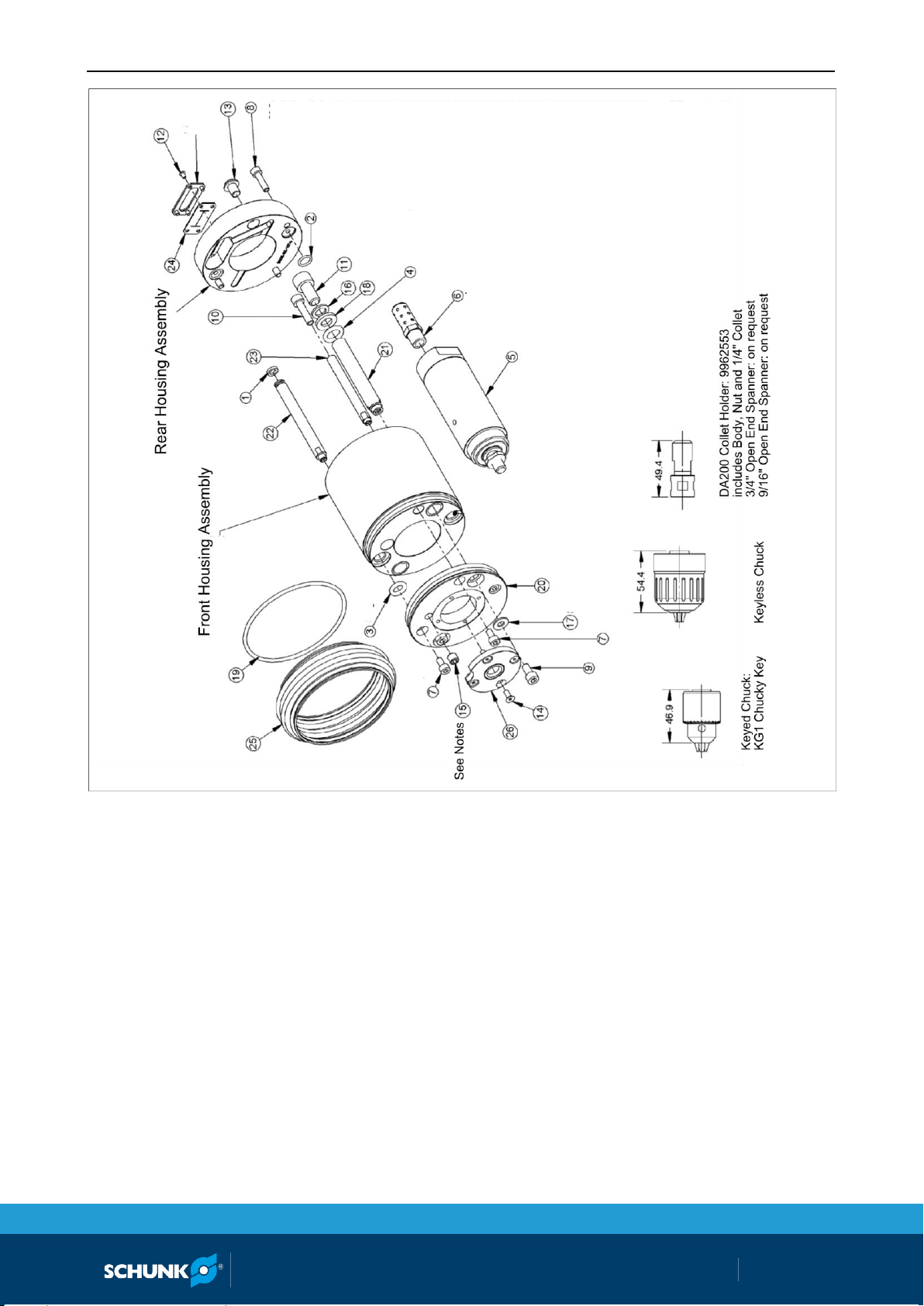
For repair and spare parts please contact SCHUNK. For an exploded drawing showing all the components of the MFT, see
( 11, Page 36).
Page 36
Drawings
36
01.00|MFT |en
11
Drawings
Page 37
Drawings
01.00|MFT |en
37
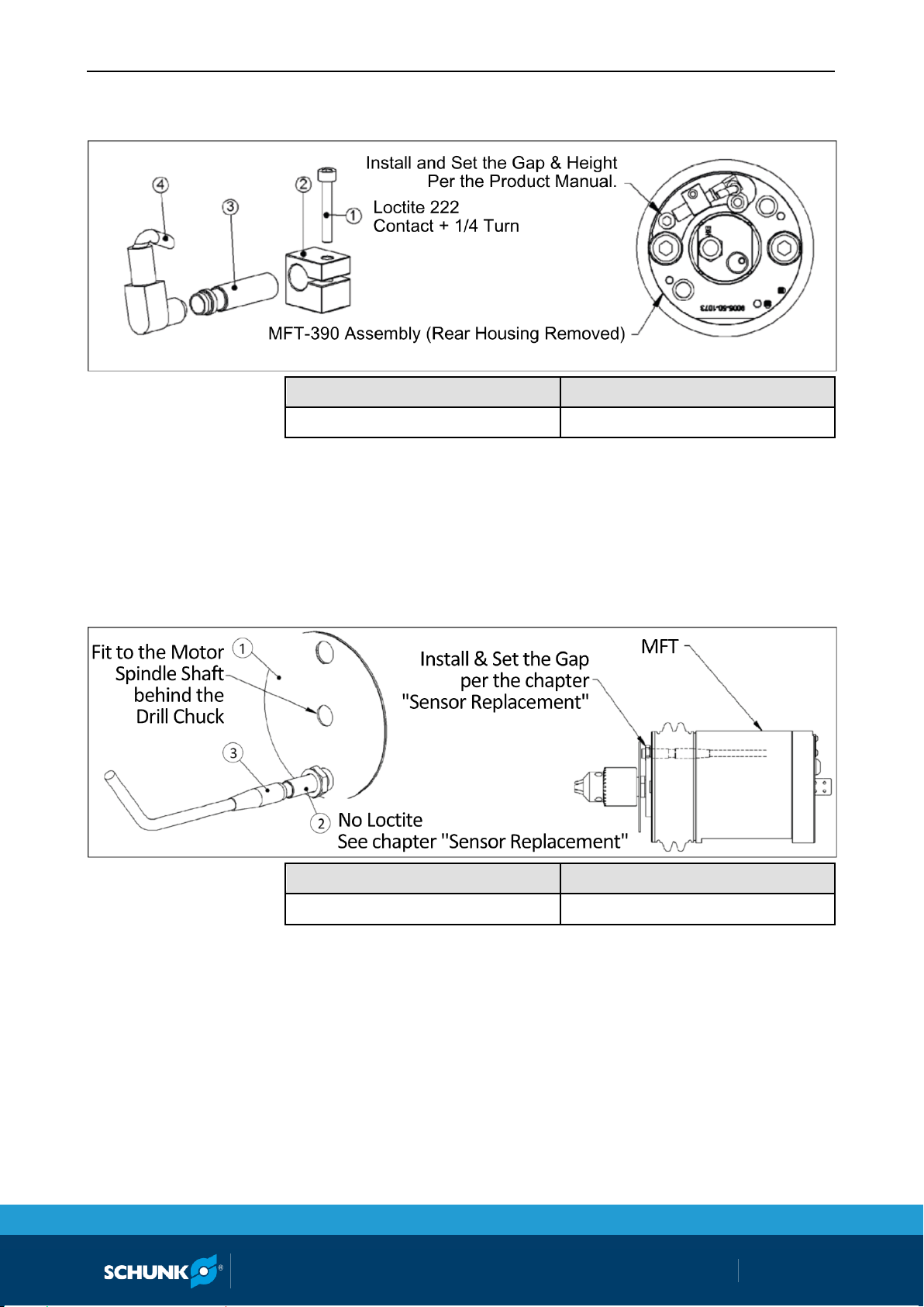
Option F - Sensor for monitoring: Spindle extracted
Designation
ID number
MFT-390-OPTION F
0322260
NOTE
The sensor is "ON" when the spindle is fully forward and not contacting the workpiece.
Designation
ID number
MFT-390 OPTION T
0322261
NOTE
• Not Available on Models with Collet Bodies
• The tachometer sensor delivers "OFF" pulses per revolution to
be monitored by the customer's process equipment. The tachometer is a process development tool and it is not recommended for production environments where the target disk
may be demaged by collisions and impacts.
Option T - Tachometer Sensor option
Page 38

Drawings
38
01.00|MFT |en
Option R - optional sensor for monitoring: Spindle retracted
Designation
ID number
MFT-390-OPTION R
0322262
NOTE
The retract sensor is "ON" when the spindle is fully backward
(Pushed backwards to the limit of travel).
Page 39
Drawings
01.00|MFT |en
39
NOTE
• Fasteners on this drawing include both torque and thread locker specifications. Thread locker (Loctite) is not required when
using new "blue" fasteners purchased from SCHUNK. Thread
locker is required anytime fasteners are being re-used.
• M8 Set Screw is used if no tachometer kit is installed. Apply
Loctite-222 to set screw and install flush with metal plate.
Page 40

Translation of original declaration of incorporation
40
01.00|MFT |en
in terms of the Directive 2006/42/EG, Annex II, Part 1.B of the European Parliament and of
the Council on machinery.
Manufacturer/
Distributor
SCHUNK GmbH & Co. KG Spann- und Greiftechnik
Bahnhofstr. 106 – 134
D-74348 Lauffen/Neckar
We hereby declare that on the date of the declaration the following incomplete machine
complied with all basic safety and health regulations found in the directive 2006/42/EC of
the European Parliament and of the Council on machinery. The declaration is rendered
invalid if modifications are made to the product.
Product designation:
Polishing Spindle / MFT /
ID number
0322250, 0322251, 0322252, 0322253,
30071281, 30072156, 30074216
The incomplete machine may not be put into operation until conformity of the machine
into which the incomplete machine is to be installed with the provisions of the Machinery
Directive (2006/42/EC) is confirmed.
The manufacturer agrees to forward on demand the relevant technical documentation for
the partly completed machinery to state offices.
The special technical documents according to Appendix VII, Part B belonging to the incomplete machine have been compiled.
Person authorized to compile the technical documentation:
Robert Leuthner, Address: see manufacturer's address
Signature – see original declaration
Lauffen/Neckar, January 2016
p.p. Ralf Winkler,
Head of Gripping Systems Development
12
Translation of original declaration of incorporation
 Loading...