

Superior Clamping and Gripping
Documentation

Superior Clamping and Gripping
Superior Clamping and Gripping
Ein Team. Eine Familie.
Bei Spanntechnik und Greifsystemen
ist SCHUNK weltweit die Nr. 1 – vom
kleinsten Parallelgreifer bis zum größten
Spann backenprogramm.
Als Kompetenzführer erkennen und
entwickeln wir Standards mit Zukunftspotenzial, die den rasanten Fortschritt
in vielen Branchen prägen.
Unsere Kunden profitieren in unserem
innovativen Familien unternehmen vom
Expertenwissen, der Erfahrung und dem
Teamgeist von über 2000 Mit arbeiterinnen und Mitarbeitern.
Weiterhin beste Ergebnisse mit unseren
Qualitäts-produkten wünschen Ihnen
One Team. One Family.
SCHUNK is the world’s No. 1 for clamping
technology and gripping systems – from
the smallest parallel gripper to the largest
chuck jaw program.
As a competence leader, we recognize and
develop standards with a large potential
for the future, which will drive the rapid
progress in many industries.
Our customers profit from the expert
knowledge, the experience and the team
spirit of more than 2000 employees in our
innovative family-owned company.
The Schunk family wishes you improved
end results with our quality products.
Heinz-Dieter Schunk
Henrik A. Schunk
Kristina I. Schunk

Linearantrieb LDx/ELB mit Antriebsregelgerät
IndraDrive CS
Inbetriebnahmeanleitung
Original Inbetriebnahmeanleitung
Linear drive LDx/ELB with drive control unit
IndraDrive CS
Commissioning instructions
Translation of the original instructions
1 01.00|IndraDrive CS |de

deutsch ................................................................................
3
english .................................................................................
32
Inhaltsverzeichnis
2 01.00|IndraDrive CS |de

Linearantrieb LDx/ELB mit
Original Inbetriebnahmeanleitung
Antriebsregelgerät
Inbetriebnahmeanleitung
Original Inbetriebnahmeanleitung
Superior Clamping and Gripping

Impressum
Sehr geehrter Kunde,
Ihre SCHUNK Electronic Solutions GmbH
Impressum
Urheberrecht:
Diese Anleitung bleibt urheberrechtlich Eigentum der SCHUNK GmbH & Co. KG. Sie wird
nur unseren Kunden und den Betreibern unserer Produkte mitgeliefert und ist Bestandteil
des Produktes. Ohne unsere ausdrückliche Genehmigung dürfen diese Unterlagen weder
vervielfältigt noch dritten Personen, insbesondere Wettbewerbsfirmen,
zugänglich gemacht werden.
Technische Änderungen:
Änderungen im Sinne technischer Verbesserungen sind uns vorbehalten.
Dokumentennummer: GAS315322
Auflage: 01.00 |29.08.2016|de
© SCHUNK GmbH & Co. KG
Alle Rechte vorbehalten
wir gratulieren zu Ihrer Entscheidung für SCHUNK. Damit haben Sie sich für höchste
Präzision, hervorragende Qualität und besten Service entschieden.
Sie erhöhen die Prozesssicherheit in Ihrer Fertigung und erzielen beste
Bearbeitungsergebnisse – für die Zufriedenheit Ihrer Kunden.
SCHUNK-Produkte werden Sie begeistern.
Unsere ausführlichen Montage- und Betriebshinweise unterstützen Sie dabei.
Sie haben Fragen? Wir sind auch nach Ihrem Kauf jederzeit für Sie da.
Mit freundlichen Grüßen
Am Tannwald 17
D-78112 St. Georgen
Tel. +49-7725-9166-0
Fax +49-7725-9166-5055
electronic-solutions@de.schunk.com
www.schunk.com
4 01.00|IndraDrive CS |de

Inh
altsverzeichnis
01.00|IndraDrive CS |de
1
Zu dieser Anleitung .................................................................................................. 6
1.1
Warnhinweise ........................................................................................................... 6
1.2
Mitgeltende Unterlagen ........................................................................................... 7
2
Grundlegende Sicherheitshinweise ........................................................................... 8
2.1
Bestimmungsgemäße Verwendung ......................................................................... 8
2.2
Umgebungs- und Einsatzbedingungen ..................................................................... 8
2.3
Produktsicherheit ..................................................................................................... 8
2.3.1
Schutzeinrichtungen ..................................................................................... 9
2.3.2
Bauliche Veränderungen, An- oder Umbauten ............................................ 9
2.4
Personalqualifikation ................................................................................................ 9
2.5
Sicherheitsbewusstes Arbeiten ................................................................................ 9
3
Inbetriebnahme ...................................................................................................... 10
3.1
Erforderliche Hilfsmittel ......................................................................................... 10
3.2
Inbetriebnahmearbeiten ........................................................................................ 10
3.2.1
Motorparameter laden ............................................................................... 14
3.2.2
Feldbus starten............................................................................................ 18
3.2.3
Betriebsart wählen ...................................................................................... 18
3.2.4
Messsystem prüfen ..................................................................................... 19
3.2.5
Funktion der Pneumatischen Haltebremse prüfen und freischalten
(opti
20
3.2.6
Absolutmaß setzen ...................................................................................... 21
3.2.7
Regelkreisüberwachung .............................................................................. 22
3.2.8
Antriebsregelgerät IndraDrive CS am Netz anschließen ............................ 22
3.2.9
Reglerfreigabe (AF) ..................................................................................... 23
3.2.10
Referenzschalter einstellen ......................................................................... 23
3.2.11
Antrieb montieren ...................................................................................... 24
3.2.12
Softwareendlage parametrieren ................................................................ 24
3.2.13
Lage- und Drehzahlregler parametrieren ................................................... 25
4
Anlagen ................................................................................................................... 26
4.1
Anschlussschema IndraDrive CS ............................................................................. 26
4.2
Bezeichnungsschlüssel der Dateien für Motoren .................................................. 28
4.3
Übersicht der Motoren ........................................................................................... 29
Inhaltsverzeichnis
onal) .....................................................................................................
5

Zu dieser Anleitung
GEFAHR
Gefahren für Personen.
WARNUNG
Gefahren für Personen.
VORSICHT
Gefahren für Personen.
ACHTUNG
Sachschaden
WARNUNG
Warnung vor gefährlicher elektrischer Spannung
1
1.1
Zu dieser Anleitung
Diese Anleitung ist integraler Bestandteil des Produktes und enthält wichtige Informationen zur sicheren und sachgerechten
Montage, Inbetriebnahme, Bedienung und Wartung sowie zur
einfachen Störungsbeseitigung.
Vor Benutzung des Produktes diese Anleitung lesen und beachten,
besonders das Kapitel "Grundlegende Sicherheitshinweise".
Warnhinweise
Zur Verdeutlichung von Gefahren werden in den Warnhinweisen
folgende Signalworte und Symbole verwendet.
Nichtbeachtung führt sicher zu irreversiblen Verletzungen bis hin
zum Tod.
Nichtbeachtung kann zu irreversiblen Verletzungen bis hin zum
Tod führen.
Nichtbeachtung kann zu leichten Verletzungen führen.
Informationen zur Vermeidung von Sachschäden.
6 01.00|IndraDrive CS |de

Zu dieser Anleitung
01.00|IndraDrive CS |de
*
www.de.schunk.com
**
www.boschrexroth.com
1.2
Mitgeltende Unterlagen
• Allgemeine Geschäftsbedingungen*
• Katalogdatenblatt des gekauften Produktes*
• Montage- und Betriebsanleitungen für Linearantriebe*
• Handbuch und Referenz zum Antriebsgerät IndraDrive CS**
Auf folgenden Seiten können die oben mit * gekennzeichneten
aufgeführten Daten alternativ online heruntergeladen werden.
7

Grundlegende Sicherheitshinweise
HINWEIS
Nähere Informationen befinden sich in den ents
2
2.1
2.2
2.3
Grundlegende Sicherheitshinweise
Bestimmungsgemäße Verwendung
Das Produkt ist zum Einbau in eine Maschine bestimmt. Die
Anforderungen der zutreffenden Richtlinien müssen beachtet und
eingehalten werden.
Eine andere oder darüber hinausgehende Verwendung gilt
als nicht bestimmungsgemäß. Für hieraus resultierende Schäden
haftet der Hersteller nicht.
Umgebungs- und Einsatzbedingungen
• Sicherstellen, dass das Produkt entsprechend dem
Anwendungsfall ausreichend dimensioniert ist.
• Sicherstellen, dass die Umgebung frei von Spritzwasser und
Dämpfen sowie von Abriebs- oder Prozessstäuben ist.
Ausgenommen hiervon sind Produkte, die speziell für
verschmutzte Umgebungen ausgelegt sind.
Produktsicherheit
Gefahren können vom Produkt ausgehen, wenn z.B.:
• das Produkt nicht bestimmungsgemäß verwendet wird.
• das Produkt unsachgemäß montiert oder gewartet wird.
• die Sicherheits- und Montagehinweise nicht beachtet werden.
Jede Arbeitsweise unterlassen, welche die Funktion und
Betriebssicherheit des Produktes beeinträchtigen.
Schutzausrüstung tragen.
prechenden Kapiteln.
8 01.00|IndraDrive CS |de

Grundlegende Sicherheitshinweise
01.00|IndraDrive CS |de
Schutzeinrichtungen
2.3.1
2.3.2
2.4
2.5
Schutzeinrichtungen gemäß EG-Maschinenrichtlinie vorsehen.
Bauliche Veränderungen, An- oder Umbauten
Zusätzliche Bohrungen, Gewinde oder Anbauten, die nicht als
Zubehör von SCHUNK angeboten werden, können die Sicherheit
beeinträchtigen, und dürfen nur mit Genehmigung von SCHUNK
durchgeführt werden.
Personalqualifikation
Die Montage, Erstinbetriebnahme, Wartung und Instandsetzung
des Moduls darf nur von geschultem Fachpersonal durchgeführt
werden.
Jede Person, die vom Betreiber mit Arbeiten am Modul beauftragt
ist, muss die komplette Montage- und Betriebsanleitung, insbesondere das Kapitel 2 "Grundlegende Sicherheitshinweise", gelesen und verstanden haben. Dies gilt insbesondere für nur gelegentlich eingesetztes Personal, z. B. Wartungspersonal.
Sicherheitsbewusstes Arbeiten
• Jede Arbeitsweise unterlassen, die die Funktion und Betriebssicherheit des Moduls beeinträchtigen.
• Die am Einsatzort gültigen Sicherheits- und Unfallverhütungsvorschriften beachten.
9

Inbe
triebnahme
GEFAHR
Lebensgefahr durch Stromschlag!
WARNUNG
Verletzungsgefahr durch Stoßen und Quetschen bei ungewollter
3
3.1
3.2
Inbetriebnahme
Erforderliche Hilfsmittel
Für die Inbetriebnahme eines Antriebs mit IndraDrive CS sind
folgende Hilfsmittel bzw. Voraussetzungen erforderlich:
• Komplett installierter Antrieb mit IndraDrive-CS
Antriebsregelgerät Anschlussschema IndraDrive CS
• PC mit Ethernet TCP/IP - Schnittstelle
• Bedienersoftware IndraWorks (ab Version 09Vxx)
• Inbetriebnahme-DVD mit den Motorparametern und den
Dateien für die Parameterauswahl.
• Ethernet (Patchkabel) Anschlusskabel PC - IndraDrive
(Bestell-Nr.336 432)
Inbetriebnahmearbeiten
Das Berühren von Spannung führenden Teilen kann zum
Tod führen.
• Arbeiten an elektrischen Anlagen oder Betriebsmitteln
dürfen nur von Elektrofachkräften den elektrotechnischen
Regeln entsprechend vorgenommen werden.
Bewegung des Systems!
Die Aktivierung des Kommandos „Automatische
Regelkreiseinstellung“ kann zu einer unkontrollierten Bewegung
des Systems führen.
• Auf keinen Fall die automatische Regelkreiseinstellung für
Motoren aktivieren.
10 01.00|IndraDrive CS |de

Inbetriebnahme
01.00|IndraDrive CS |de
1 Antriebsregelgerät IndraDrive CS mit PPU- E und übergeordne-
ter Steuerung gemäß den Anschlussschemen verdrahten.
2 Verbindung zwischen PC und Steuerung herstellen.
ACHTUNG: Das Regelgerät hat die IP Adresse
192.168.0.1(Standardeinstellung) bei Profibus Geräten ist die
IP Adresse 192.168.1.1 Die PC Schnittstelle muss eine ähnliche
IP Adresse haben z.B. 192.168.0.11 und Subnetzmaske muss
ebenso identisch sein 255.255.255.0.
3 Um die IP Adresse einzustellen muss die Enter Taste gedrückt
werden. Es erscheint dann das Menu:
Danach auf Menüpunkt 2.3.7 gehen. Dort kann die IP Adresse
eingestellt werden. (Achtung die IP Adresse darf nicht dieselbe
sein. Fortlaufende IP Verteilung ist erwünscht.)
Abb. 1
4 Mit den Pfeiltasten weiter drücken bis das Menu „EtherNet“
erscheint.
Abb. 2
5 Danach mit „Enter“ bestätigen
11

Inbe
triebnahme
Abb. 3
6 Danach mit „Enter“ bestätigen. Nun mit den Pfeiltasten die IP
Adresse nach Ihrem Wunsch einstellen.
Abb. 4
7 Mit den Pfeiltasten auf die Subnetzmaske umstellen
Abb. 5
8 Im Menüpunkt Subnet-Mask kann die Adresse eingestellt
12 01.00|IndraDrive CS |de
werden. Bei Anlieferung steht die Adresse auf 255.255.255.0

Inbetriebnahme
01.00|IndraDrive CS |de
Abb. 6
9 5. Einstellen der Sercos Adresse
Im Hauptbildschirm Taste „Enter“ drücken und danach mit
den Pfeiltasten, das Menu Slave auswählen und "Enter"
drücken.
Abb. 7
10 Die gewünschte Nummer eingeben und mit der Enter bestätigen.
11 Mit der "Esc" Taste zurück in den Hauptbildschirm.
13

Inbe
triebnahme
HINWEIS
Die Arbeiten in diesem Kapitel müssen nur ausgeführt werden,
wenn keine Daten auf dem Regler vorinstalliert wurden.
Das nachfolgend beschriebne Einstellen des Reglers auf Sercos III
Kommunikation erfolgt über das Front Side Panel .
3.2.1
Motorparameter laden
Abb. 8 Front Side Panel
1 Die [Enter] Taste viermal betätigen. Im Display blinkt die ge-
wünschte Feldbusvariante.
2 Nun Sercos III mit den Pfeiltasten
auswählen.
3 Die Auswahl mit der [Enter] Taste bestätigen.
Im Display steht jetzt Sercos III und blinkt nicht mehr.
4 Die 24V Versorgung ausschalten und wieder einschalten.
Der Regler bootet von neuem und Sercos III ist aktiviert. Zur
Kontrolle: Nach dem Hochfahren müsste P -1 im Display
stehen.
5 IndraWorks DS auf PC starten.
14 01.00|IndraDrive CS |de

Inbetriebnahme
01.00|IndraDrive CS |de
Abb. 9
HINWEIS
Die Bedienung von IndraWorks ist im Hilfemenü des Programms
erklärt.
7 Im Hauptfenster von IndraWorks Menü <Ansicht> → <Projekt-
explorer > wählen.
Der Projektexplorer öffnet sich.
6 Ethernet anwählen und IP Suchbereich einstellen.
Abb. 10 Projektexplorer
15

Inbe
triebnahme
Abb. 11
8 <IndraDrive > mit der rechten Maustaste auswählen und
anschließend im Kontextmenü <Parameter> → <Laden>
auswählen:
9 Linearmotortyp wählen
Es öffnet sich das Dialogfenster:
Abb. 12 Motorparameter importieren
16 01.00|IndraDrive CS |de

Inbetriebnahme
01.00|IndraDrive CS |de
11 Ordner <Motorparameter> unter <LDx_Linearmotor> und
<IndraDrive> auf der Inbetriebnahme-CD IndraDrive auswäh-
len.
11 Zutreffende Motorparameter-Datei auswählen
12 Im Dialogfenster den Ordner des gewünschten Linearmotor-
typs auswählen.
13 Im nächsten Dialogfenster gewünschte Motorparameter-Datei
auswählen und öffnen. Die Motorparameter werden geladen:
Abb. 13 Motorparameter Laden
17

Inbe
triebnahme
WARNUNG
Eine falsch eingestellte Betriebsart kann zu ungewollten Bewe-
parametrieren.
3.2.2
3.2.3
Feldbus starten
1 Feldbus-Schnittstelle gemäß der Hersteller-Dokumentation
IndraDrive CS und den Schaltschrank-Unterlagen parametrieren.
2 Feldbus anschließen und starten.
3 Die Beschaltung abhängig von der Feldbus-Schnittstelle für
Reglerfreigabe, Halt, Referenzschalter und Endschalter
realisieren und kontrollieren.
Betriebsart wählen
gungen des Antriebs führen.
• Auf keinen Fall die Betriebsarten „Momentregelung“ und „
Geschwindigkeitsregelung“ einstellen.
• Die Schleppfehlerüberwachung aktivieren und sinnvoll
• Die Steuerung in den Betriebsmodus (Phase 4) schalten.
Im Display des Standard-Bedienfelds am Antriebsregelgerät
IndraDrive CS wird bb angezeigt.
Abb. 14
18 01.00|IndraDrive CS |de

Inbetriebnahme
01.00|IndraDrive CS |de
3.2.4
Messsystem prüfen
1 In der Strukturansicht des Projektexplorers über
<IndraDrive> → <Anwendungsart> auswählen.
2 <Anwendungsart> mit der rechten Maustaste auswählen und
anschließend im Kontextmenü <Diagnose> → <Status>
auswählen. Das Dialogfenster des Ordners <Status> öffnet sich.
Abb. 15 Status prüfen
Anzeige und Skalierung des Messsystems prüfen
1 Führungsschlitten von Hand verschieben. Es dürfen keine
Sprünge in der Anzeige „Position“ auftreten.
2 Maßstab (etwa 10 cm) an den Führungsträger legen und
Führungsschlitten am Maßstab entlang verschieben.
3 Den gemessenen Verfahrweg mit der Anzeige der Ist-Position
vergleichen.
19
Inbe
triebnahme
ACHTUNG
Führungsträger und pneumatische Haltebremse können durch
3.2.5
Funktion der Pneumatischen Haltebremse prüfen und freischalten (optional)
gewaltsames Verschieben des Führungsschlittens beschädigt
werden.
Schäden an der Linearmotor-Achse möglich!
• Den Führungsträger oder Führungsschlitten nie gewaltsam bei
aktiver Haltebremse bewegen.
• Nur mit geringer Kraft den Führungsschlitten bewegen, um die
Funktion der pneumatischen Haltebremsen zu prüfen.
1 Den Führungsschlitten bei aktiver Haltebremse vorsichtig von
Hand auf Bewegung prüfen. Der Führungsschlitten darf sich
nicht bewegen.
2 24-V-Anschluss an das Bremsventil anlegen. Die pneumatische
Haltebremse ist freigeschaltet (optional).
20 01.00|IndraDrive CS |de

Inbetriebnahme
01.00|IndraDrive CS |de
Absolutmaß setzen
3.2.6
Dieser Abschnitt wird nur benötigt, wenn ein Absolutmesssystem
eingesetzt wird. (TTK 70)
Abb. 16 Absolutmaß setzen
1 In der Strukturansicht des Projektexplorers über
<IndraDrive> → <Motor, Bremse, Messsysteme> →
<Motorgeber> → <Maßbezug Motorgeber> auswählen.
2 Die Achse in die gewünschte Position bringen und den Button
< Absolutmaß setzen > betätigen.
3 Eine gewünschte Offsetverschiebung kann im Feld
<Referenzmaß> eingegeben werden.
21
Inbe
triebnahme
ACHTUNG
Schäden am Führungsschlitten und Führungsträger möglich!
3.2.7
3.2.8
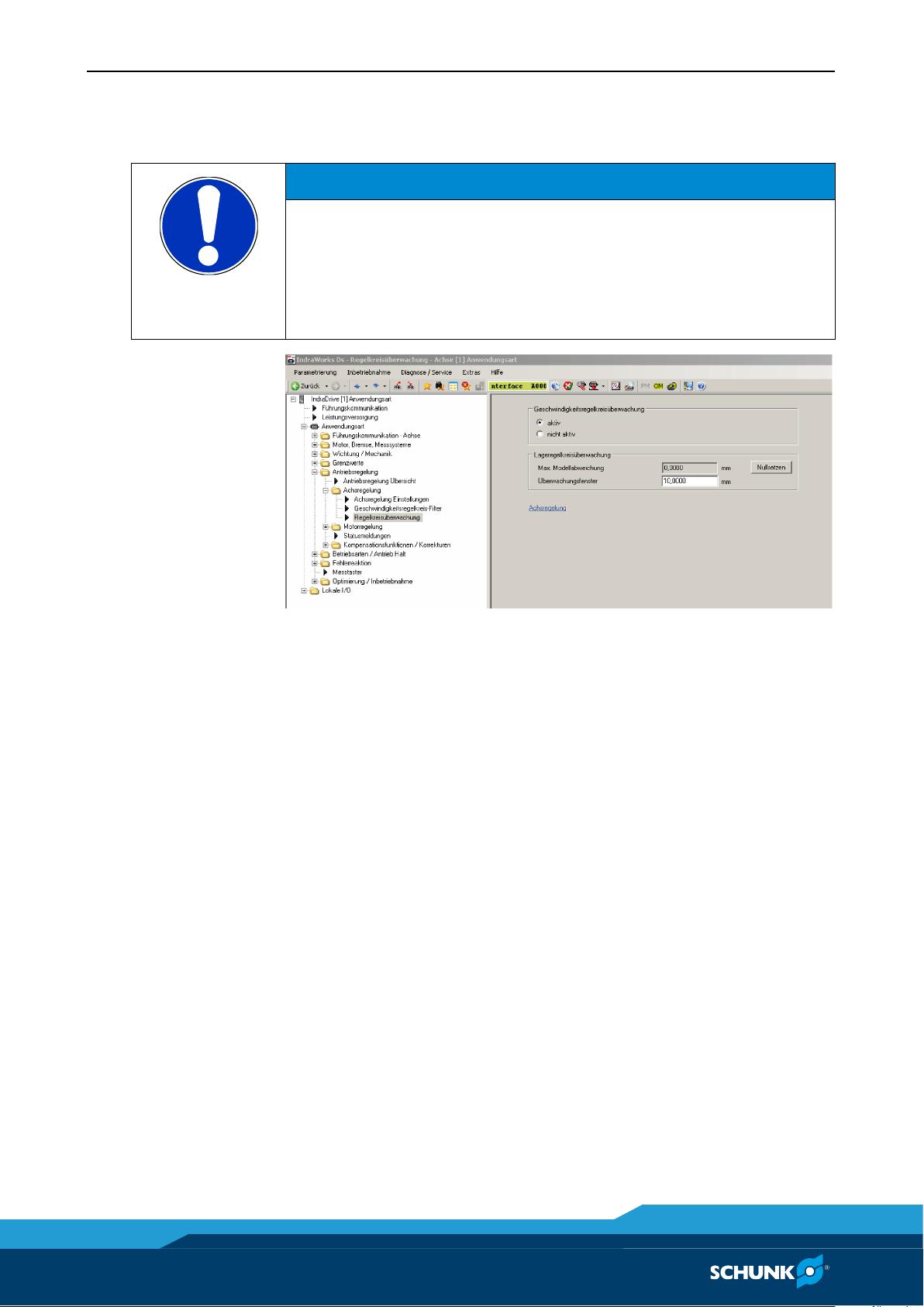
Regelkreisüberwachung
Ein deaktiviertes oder zu groß eingestelltes Regelkreisüberwachungsfenster kann zu einem Crash des Führungsschlittens führen.
• Die Lageregelkreisüberwachung sinnvoll parametrieren.
Abb. 17 Regelkreisüberwachung
1 In der Strukturansicht des Projektexplorers
<IndraDrive> → <Motion> → <Achse> → <Regelung> →
<Achsregelung> → <Regelkreisüberwachung> auswählen.
Das Dialogfenster <Regelkreisüberwachung> öffnet sich:
2 Optionsfeld <Geschwindigkeitsregelkreisüberwachung>
aktivieren.
3 Lageregelkreisüberwachung parametrieren.
Antriebsregelgerät IndraDrive CS am Netz anschließen
• Spannung am Steuerschaltschrank einschalten
(Netzanschluss 380 V).
Am Display des Standard-Bedienfelds am Antriebsregelgerät
IndraDrive CS erscheint die Anzeige AB, das Antriebsregelgerät
IndraDrive CS ist am Netz angeschlossen.
22 01.00|IndraDrive CS |de
Inbetriebnahme
01.00|IndraDrive CS |de
HINWEIS
Die Reglerfreigabe kann, abhängig vom Feldbus-System, Hardware- oder Softwareseitig zugeschaltet werden.
HINWEIS
Parametrierung gemäß der Funktionsbeschreibung in der
Dokumentation des Antriebsregelgeräts Rexroth IndraDrive CS
vornehmen.
3.2.9
3.2.10
Reglerfreigabe (AF)
1 Reglerfreigabe (AF) zuschalten.
2 „Halt“ zuschalten.
Im Display des Standard-Bedienfelds am Antriebsregelgerät
IndraDrive CS erscheint die Anzeige AF oder mit AH .
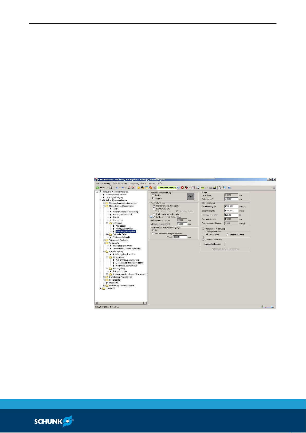
Referenzschalter einstellen
1 In der Strukturansicht des Projektexplorers <IndraDrive> →
<Motor, Bremse, Messsysteme> → <Motorgeber> →
<Maßbezug herstellen> auswählen.
Das Dialogfenster <Maßbezug Motorgeber> öffnet sich:
Abb. 18 Maßbezug Motorgeber
2 Über Feldbus Führungsschlitten langsam in beide Richtungen
verfahren.
3 Richtung, Geschwindigkeit und Beschleunigung referenzieren,
parametrieren und testen.
23

Inbe
triebnahme
3.2.11
3.2.12
Antrieb montieren
1 Alle bewegten Baugruppen (bewegte Masse) montieren.
2 Antrieb in der vorgesehenen Lage anordnen.
Softwareendlage parametrieren
1 In der Strukturansicht des Projektexplorers <IndraDrive> →
<Grenzwerte> → <Bewegungsgrenzwerte> auswählen.
Das Dialogfenster <Bewegungsgrenzwerte> öffnet sich:
Abb. 19 Bewegungsgrenzwerte
2 Optionsfeld <Lagegrenzwertüberwachung> aktivieren.
3 Optionsfeld <Überwachung Fahrbereichsgrenzschalter>
4 Bewegungsgrenzwerte im Dialogfenster einstellen.
24 01.00|IndraDrive CS |de
aktivieren.

Inbetriebnahme
01.00|IndraDrive CS |de
HINWEIS
Parametrierung gemäß der Funktionsbeschreibung in der
Dokumentation des Antriebsregelgeräts Rexrot
vorne
(Closed
3.2.13
Lage- und Drehzahlregler parametrieren
1 In der Strukturansicht des Projektexplorers
<IndraDrive> → <Motion> → <Achse> → <Achsregelung> →
<Achsregelung Einstellungen> auswählen. Das Dialogfenster
<Achsregelung Einstellungen> öffnet sich:
Abb. 20 Achsregelung Einstellungen
2 Feineinstellungen für Lageregler und Drehzahlregler vorneh-
men.
h IndraDrive CS
hmen (Kapitel <Antriebsregelung>, Abschnitt <Achsregelung
-Loop-Betrieb)>.
25

Anlagen
4
4.1
Anlagen
Anschlussschema IndraDrive CS
Abb. 21 Anschlussschema IndraDrive CS
26 01.00|IndraDrive CS |de

Anlagen
Abb. 22 Anschlussschema IndraDrive CS
01.00|IndraDrive CS |de
27

Anlagen
4.2
Bezeichnungsschlüssel der Dateien für Motoren
Abb. 23 Bezeichnungsschlüssel der Dateien für Motoren
28 01.00|IndraDrive CS |de

Anlagen
4.3
Übersicht der Motoren
01.00|IndraDrive CS |de
29

Anlagen
30 01.00|IndraDrive CS |de

Anlagen
01.00|IndraDrive CS |de
31

Translation of the original instructions
Linear drive LDx/ELB with drive control unit
IndraDrive CS
Commissioning instructions
Translation of the original instructions
Superior Clamping and Gripping

Imprint
01.00|IndraDrive CS |en
Imprint
Dear customer,
Your SCHUNK Electronic Solutions GmbH
Copyright:
This manual remains the copyrighted property of SCHUNK GmbH & Co. KG. It is solely
supplied to our customers and operators of our products and forms part of the product.
This documentation may not be duplicated or made accessible to third parties, in particular competitive companies,
without our prior permission.
Technical changes:
We reserve the right to make alterations for the purpose of technical improvement.
Document number: GAS315322
Edition: 01.00 |29/08/2016|en
© SCHUNK GmbH & Co. KG
All rights reserved.
congratulations on choosing a SCHUNK product. By choosing SCHUNK, you have opted for
the highest precision, top quality and best service.
You are going to increase the process reliability of your production and achieve best
machining results – to the customer's complete satisfaction.
SCHUNK products are inspiring.
Our detailed assembly and operation manual will support you.
Do you have further questions? You may contact us at any time – even after purchase.
Kindest Regards
Am Tannwald 17
D-78112 St. Georgen
Tel. +49-7725-9166-0
Fax +49-7725-9166-5055
electronic-solutions@de.schunk.com
www.schunk.com
33

Table of contents
1
About this manual ................................................................................................... 35
1.1
Warnings ................................................................................................................. 35
1.2
Applicable documents ............................................................................................ 36
2
Basic safety notes ................................................................................................... 37
2.1
Appropriate use ...................................................................................................... 37
2.2
Ambient conditions and operating conditions ....................................................... 37
2.3
Product safety......................................................................................................... 37
2.3.1
Protective equipment ................................................................................. 38
2.3.2
Constructional changes, attachments, or modifications ............................ 38
2.4
Personnel qualification ........................................................................................... 38
2.5
Safety-conscious working ....................................................................................... 38
3
Commissioning ........................................................................................................ 39
3.1
Necessary tools & resources .................................................................................. 39
3.2
Commissioning work .............................................................................................. 39
3.2.1
Loading the motor parameters ................................................................... 43
3.2.2
Starting field bus ......................................................................................... 47
3.2.3
Selecting operating mode ........................................................................... 47
3.2.4
Testing measuring system ........................................................................... 48
3.2.5
Check that the pneumatic brake (optional) works and enable it ............. 49
3.2.6
set absolute measurement ......................................................................... 50
3.2.7
Control loop monitoring ............................................................................. 51
3.2.8
Drive control unit IndraDrive CS Connect to the network .......................... 51
3.2.9
Enabling the controller ................................................................................ 51
3.2.10
Set reference controller .............................................................................. 52
3.2.11
Mounting the drive ..................................................................................... 53
3.2.12
Set the parameters for the software controlled limits ............................... 53
3.2.13
Set the parameters for the position and speed controllers ....................... 54
4
Appendices.............................................................................................................. 55
4.1
Connection diagram IndraDrive CS ........................................................................ 55
4.2
Designation key of files for motors ........................................................................ 57
4.3
Overview of motor types ........................................................................................ 58
Table of contents
34 01.00|IndraDrive CS |en

About this manual
01.00|IndraDrive CS |en
DANGER
Danger for persons.
WARNING
Dangers for persons.
CAUTION
Dangers for persons.
NOTICE
Material damage
WARNING
Warning about dangerous electrical voltage
1
1.1
About this manual
This instruction is an integral part of the product and contains important information for a safe and proper assembly, commissioning, operation, maintenance and help for easier trouble shooting.
Before using the product, read and note the instructions, especially the chapter "Basic safety notes".
Warnings
To make risks clear, the following signal words and symbols are
used for safety notes.
Non-compliance will inevitably cause irreversible injury or death.
Ignoring a safety note like this can lead to irreversible injury and
even death.
Non-observance can cause minor injuries.
Information about avoiding material damage.
35

About this manual
*
www.de.schunk.com
**
www.boschrexroth.com
1.2
Applicable documents
• General terms of business*
• Catalog data sheet of the purchased product*
• Assembly and operating manuals for linear motor drive*
• Manual and references for control unit IndraDrive CS**
On the following pages, the data which is marked with *, can be
downloaded alternatively.
36 01.00|IndraDrive CS |en

Basic safety notes
01.00|IndraDrive CS |en
NOTE
More information are contained in the relevant chapters.
2
2.1
2.2
2.3
Basic safety notes
Appropriate use
The product is intended for installation in a machine/system.The
requirements of the applicable guidelines must be observed and
complied with.
Any other use or use exceeding that specified is an infringement of
use for intended purpose. The manufacturer bears no liability for
damage resulting from such use.
Ambient conditions and operating conditions
• Make sure that the product has a sufficient size for the
application.
• Make sure that the environment is free from splash water and
vapors as well as from abrasion or processing dust. Exceptions
are products that are designed especially for contaminated environments.
Product safety
Dangers arise from the product, if:
• the product is not used in accordance with its intended
purpose.
• the product is not installed or maintained properly.
• the safety and installation notes are not observed.
Avoid any manner of working that may interfere with the function
and operational safety of the product.
Wear protective equipment.
37

Basic safety notes
2.3.1
2.3.2
2.4
2.5
Protective equipment
Provide protective equipment per EC Machinery Directive.
Constructional changes, attachments, or modifications
Additional drill holes, threads, or attachments that are not offered
as accessories by SCHUNK may be attached only with permission
of SCHUNK.
Personnel qualification
The assembly, initial commissioning, maintenance, and repair of
the module may be performed only by trained specialist
personnel.
Every person called upon by the operator to work on the module
must have read and understood the complete Assembly and Operating Manual, especially chapter 2 "Basic safety notes". This applies particularly to occasional personnel such as maintenance
personnel.
Safety-conscious working
• Avoid any manner of working that may interfere with the function and operational safety of the module.
• Observe the safety and accident-prevention regulations valid at
the usage site.
38 01.00|IndraDrive CS |en

Commissioning
01.00|IndraDrive CS |en
DANGER
Danger to life due to electric shock!
WARNING
Risk of injury due to crushing and squeezing in unwanted
3
3.1
3.2
Commissioning
Necessary tools & resources
The following tools & resources are needed to start up a drive with
an IndraDrive CS unit.
• a fully installed drive with an IndraDrive CS drive control unit
for connection schematics IndraDrive CS Connection diagram
IndraDrive CS
• PC with Ethernet TCP/IP interface
• IndraWorks operating software (from Version 08Vxx)
• Commissioning CD with the motor parameters and the files for
parameter selection.
Commissioning work
Touching live parts can cause death.
• Only professional electricians may carry out work on electrical
systems and equipment under compliance of the rules for
working with electrical systems.
movement of the system!
Activating the “Automatic set up of the control circuit” command
can lead to a crash of the guided slide.
• Under no circumstances activate the automatic set up of the
control circuit for motors.
39

Commissioning
1 Wire drive control unit IndraDrive to motor and higher-order
controller in accordance with the connection schematics.
2 Create connection between PC and controller.
ATTENTION
The control unit has the IP address 192.168.0.1
(default setting) a Profibus device has the IP address
192.168.0.1.1. The PC interface must have a similar IP address,
e.g. 192.168.0.11 the subnet mask must also be identical:
255.255.255.0.
3 To set the IP address, the Enter key must be pressed. It ap-
pears the menu: There, the IP address can be set. (Please note
that the IP address may not be the same. Ongoing IP distribution is desired.)
Fig. 1
4 Use the arrow keys to navigate to "EtherNet" menu
Fig. 2
5 Then confirm with "Enter"
40 01.00|IndraDrive CS |en

Commissioning
01.00|IndraDrive CS |en
Fig. 3
6 Then confirm with "Enter". Set the ip address with the arrow
keys.
Fig. 4
7 Setting up the subnet mask with the arrow keys
Fig. 5
8 This can be set in menu option subnet mask. On delivery, it is
set to 255.255.255.0.
41

Commissioning
Fig. 6
9 5. Setting up the Sercos address.
Press the "Enter" key on the main screen, then use the ar-
row keys to select the menu "slave" and confirm with "Enter".
Fig. 7
42 01.00|IndraDrive CS |en
10 Enter the desired number and press the Enter key.
11 Press the "Esc" key to return to the main screen.

Commissioning
01.00|IndraDrive CS |en
Loading the motor parameters
NOTE
The work in this chapter is only necessary if no data has been preinstalled in the control unit.
Set the control unit to Sercos III communication. This is done using
the front side panel.
3.2.1
Fig. 8 front side panel
1 Press the [Enter] button four times. The desired field bus vari-
ant will flash on the display.
2 Now use the cursor keys to select Sercos III.
3 Confirm your selection with the [Enter] button.
Sercos III will now be shown in the display and will no longer
flash.
4 Switch off the 24 V supply and then switch it back on again.
The control unit will reboot and Sercos III will be activated.
To verify: After starting up the display should show P -1.
5 Start IndraWorks DS on the PC.
43

Commissioning
NOTE
The program's help menu explains how to use IndraWorks.
Fig. 9
6 Select Ethernet and set the IP search range.
7 In the main window of IndraWorks <View> menu Select
<Project explorer>
The project explorer will open.
Fig. 10 Project explorer
44 01.00|IndraDrive CS |en

Commissioning
01.00|IndraDrive CS |en
Fig. 11
8 Right click <IndraDrive > and then select <Parameters> from
the resulting context menu Select <Load>:
9 Select type of linear motor
The window will open:
Fig. 12 Import motor parameters
45

Commissioning
10 Select file <Motor parameter> under <LDx_Linearmotor> and
<IndraDrive> on the commissioning-CD IndraDrive.
11 Select the appropriate motor parameter file.
12 Select the folder of the desired linear motor types in the dia-
log box.
13 Select desired motor parameter file in the next dialog box and
open it.
Fig. 13 Loading motor parameters
46 01.00|IndraDrive CS |en

Commissioning
01.00|IndraDrive CS |en
Starting field bus
WARNING
If the operating mode is incorrectly set, this may lead to un-
3.2.2
3.2.3
1 Configure field bus interface in accordance with IndraDrive CS
manufacturer documentation and control cabinet
documentation.
2 Connect and start field bus.
3 Implement and check the wiring for controller enable, stop,
reference switch and limit switch, depending on the field bus
interface.
Selecting operating mode
wanted movements of the drive.
• Under no circumstances set the operating modes “Torque
control” or “Speed control”
• Activate the drag fault monitoring and configure it sensibly.
• Switch the control unit into the operating mode (phase 4).
In the standard control display on drive control unit IndraDrive CS
BB will be displayed.
Fig. 14
47

Commissioning
3.2.4
Testing measuring system
1 In the tree view of the project Explorer, select folder
<IndraDrive> → <Application>.
2 Right click <Application> and then select <Diagnosis> →
<Status> from the resulting context menu. The dialog box for
the <Status> folder appears.
Fig. 15 checking status
1 Move the carriage by hand. There should be no leaps in the
display "position".
2 Apply a Scale (about 10 cm) on the guide blade carriage and
move carrier along the scale.
3 Compare the measured travel distance with the display of the
actual position.
48 01.00|IndraDrive CS |en

Commissioning
01.00|IndraDrive CS |en
NOTICE
Forcibly moving the guided slide can result in damage to the
whether the pneumatic brake is working.
3.2.5
Check that the pneumatic brake (optional) works and enable it
guide rail and the pneumatic brake.
Possible damage to the linear motor axis.
• Never forcibly move the guide rail or the guided slide when
the holding brake is active.
• Only apply a low force to try to move the guided slide to see
1 Carefully try to move the guided slide with the holding brake
on. The guided slide must not move.
2 Attach the 24 V connection to the brake valve. The pneumatic
brake (optional) is then enabled.
49

Commissioning
3.2.6
set absolute measurement
This part is only required if Absolute measuring system is used.
(TTK 70)
Fig. 16 Set absolute measurement
1 Select the project explorer via the overview structure:
<IndraDrive> → <Motor, Brake, Measuring System> →
<Motor encoder> → <Reference between the motor encoder>
2 Bring the axis into the desired position and press the button
<Set absolute measurement>.
3 A desired offset shift can be entered in field
<Reference measurement>
50 01.00|IndraDrive CS |en

Commissioning
01.00|IndraDrive CS |en
Control loop monitoring
NOTICE
Damage to the carriage and guide blade carrier is possible!
• Set useful control loop monitor parameters.
NOTE
The controller can, depending on the field bus system, be enabled
either by hardware or software.
3.2.7
3.2.8
3.2.9
A disabled or set too high loop monitoring window can lead to a
crash of the carriage.
Fig. 17 Control loop monitoring
1 In the tree view of the project explorer, select
<IndraDrive> → <Motion> → <Axis> → <Controller> →
<Axis control> Select <Control circuit monitor>.
The <Control circuit monitor> window will open:
2 Activate the <Speed control circuit monitor> field
3 Set the parameters for the position control circuit monitor.
Drive control unit IndraDrive CS Connect to the network
• Switch the power on at the control switching cabinet
(380 V supply).
On the display of the standard control panel on the Drive control
unit IndraDrive CS, Ab will be displayed, showing that the Drive
control unit IndraDrive CS is connected to the power supply
Enabling the controller
1 Activate controller enable (AF).
2 Activate “stop“.
"AF" or hold "AH" appears on the display of the standard operating
field of the drive control unit IndraDrive CS.
51

Commissioning
NOTE
Perform Parameterization according to the functional description
in the documentation of the drive controller Rexroth IndraDrive
CS.
3.2.10
Set reference controller
1 Select the project explorer via the overview structure:
<IndraDrive> → <Motor, Brake, Measuring System> →
<Motor encoder> → <assign measurements>
The <assign measurement motor encoeder> window will
open:
Fig. 18 assign measurement motor encoeder
2 Move the guide carriage with Field bus slowly in both direc-
tions .
3 Test and parameterize the direction, speed and acceleration .
52 01.00|IndraDrive CS |en

Commissioning
01.00|IndraDrive CS |en
Mounting the drive
3.2.11
3.2.12
1 Mount all moving modules (moving mass).
2 Move drive to the intended position.
Set the parameters for the software controlled limits
1 In the tree view of the Project Explorer, select
<IndraDrive> → <Limit values> → <Motion limit values>.
The dialog box <Motion Limit Values> appears:
Fig. 19
2 Activate the <Position limit value monitoring> option field.
3 Activate the <Velocity Loop Monitoring> option field.
4 Set motion limit values in the dialog box.
53

Commissioning
NOTE
Set the parameters as specified in the functional description in the
documentation for the Rexroth Drive control unit IndraDrive CS
(chapter <Drive controller>, section <axis control
(closed loop mode)>.
3.2.13
Set the parameters for the position and speed controllers
1 In the tree view of the Project Explorer, select
<IndraDrive> → <Drive control> → <> → <Axis control> →
<Axis control settings>. The dialog box <Axis control> appears:
Fig. 20 Axis control settings
2 Make the fine adjustments for the position and speed
controllers.
54 01.00|IndraDrive CS |en

Appendices
01.00|IndraDrive CS |en
4
4.1
Appendices
Connection diagram IndraDrive CS
Fig. 21 Connection diagram IndraDrive CS
55

Appendices
Fig. 22 Connection diagram IndraDrive CS
56 01.00|IndraDrive CS |en

Appendices
01.00|IndraDrive CS |en
4.2
Designation key of files for motors
Fig. 23 Designation key of files for motors
57

Appendices
4.3
Overview of motor types
58 01.00|IndraDrive CS |en

Appendices
01.00|IndraDrive CS |en
59

Appendices
60 01.00|IndraDrive CS |en


Exceptional Precision from the Competence Leader for Clamping Technology and Gripping Systems.
info@de.schunk.com
www.schunk.com
www.youtube.com/SCHUNKHQ
www.twitter.com/SCHUNK_HQ
www.facebook.com/SCHUNK.HQ
2013-03-21 © 2013 SCHUNK GmbH & Co. KG
 Loading...