


Original Software Manual
Software Manual
SCHUNK Software Module for URCap
SCHUNK Sensor FT-AXIA 80 Ethernet

Imprint
Imprint
Copyright:
This manual is protected by copyright. The author is SCHUNK GmbH & Co. KG. All rights reserved. Any reproduction, processing, distribution (making available to third parties),
translation or other usage - even excerpts - of the manual is especially prohibited and requires our written approval.
Technical changes:
We reserve the right to make alterations for the purpose of technical improvement.
Document number: 1369443
Version: 01.00|05/09/2018|en
© SCHUNK GmbH & Co. KG
All rights reserved.
Dear Customer,
thank you for trusting our products and our family-owned company, the leading techno-
logy supplier of robots and production machines.
Our team is always available to answer any questions on this product and other solutions.
Ask us questions and challenge us. We will find a solution!
Best regards,
Your SCHUNK team
SCHUNK GmbH & Co. KG
Spann- und Greiftechnik
Bahnhofstr. 106 – 134
D-74348 Lauffen/Neckar
Tel. +49-7133-103-0
Fax +49-7133-103-2399
info@de.schunk.com
schunk.com
2
01.00 | SCHUNK Software Module for URCap | Software Manual | en | 1369443

Table of contents
Table of contents
1 About this manual ................................................................................................... 4
1.1 Explanation of Warnings ...................................................................................... 5
2 Safety ...................................................................................................................... 6
2.1 General Safety Guidelines ....................................................................................6
2.2 Safety Precautions................................................................................................ 6
3 Overview ................................................................................................................. 7
3.1 UR Kit.................................................................................................................... 8
3.1.1 Unpacking the UR Kit................................................................................9
3.1.2 Installing the Ethernet AXIA Sensor..........................................................9
4 URCap Software......................................................................................................10
4.1 Installing URCap Software .................................................................................. 11
4.2 Setting up URCap Software ................................................................................ 14
4.3 Determining the Tooling Mass and Offset.......................................................... 17
4.4 Uninstalling URCap Software.............................................................................. 19
5 Operation of the URCap Software...........................................................................21
5.1 Sample Rate........................................................................................................ 22
5.2 View Force and Torque Readings .......................................................................22
5.3 Program Node Commands and Options............................................................. 23
5.3.1 Program Node Commands .....................................................................26
5.3.2 Program Node Options...........................................................................28
5.3.3 Protective Stop Error ..............................................................................33
6 Demo Programs ......................................................................................................34
6.1 Downloading Demo Programs............................................................................ 35
6.2 Installing Demo Programs and Setting a Start Position ...................................... 35
7 Operation ...............................................................................................................41
7.1 Standard Demo Program.................................................................................... 41
7.2 Simple Demo ...................................................................................................... 42
8 Troubleshooting .....................................................................................................43
8.1 Errors with the URCap Software......................................................................... 44
01.00 | SCHUNK Software Module for URCap | Software Manual | en | 1369443
3

About this manual
1 About this manual
This manual contains important information for a safe and appropriate use of the product.
This manual is an integral part of the product and must be kept accessible for the personnel at all times.
Before starting work, the personnel must have read and understood this operating manual. Prerequisite for safe working is the
observance of all safety instructions in this manual.
Illustrations in this manual are provided for basic understanding
and may differ from the actual product design.
In addition to these instructions, the documents listed under Link
Mitgeltende Unterlagen are applicable.
4
01.00 | SCHUNK Software Module for URCap | Software Manual | en | 1369443

About this manual
1.1 Explanation of Warnings
The warnings included here are specific to the product(s) covered
by this manual. It is expected that the user heed all warnings from
the robot manufacturer and/or the manufacturers of other components used in the installation.
DANGER
Danger for persons!
Non-observance will inevitably cause irreversible injury or death.
CAUTION
Dangers for persons!
Non-observance can cause minor injuries.
WARNING
Dangers for persons!
Non-observance can lead to irreversible injury and even death.
NOTICE
Material damage!
Information about avoiding material damage.
01.00 | SCHUNK Software Module for URCap | Software Manual | en | 1369443
5

Safety
2 Safety
The safety section describes general safety guidelines to be followed with this product, explanation of the notification found in
this manual, and safety precaution that apply to the product. More
specific notification are imbedded within the sections of the
manual where they apply.
2.1 General Safety Guidelines
The customer should verify that the transducer selected is rated
for maximum loads and torques expected during operation. Because static forces are less than the dynamic forces from the acceleration or declaration of the robot, be aware of the dynamic loads
caused by the robot.
2.2 Safety Precautions
NOTICE
Material damage due to wrong up setting.
When initially setting up the Demo Programs, position the robot
manually in order to avoid damaging parts, especially the sensor
cable.
6
01.00 | SCHUNK Software Module for URCap | Software Manual | en | 1369443

Overview
3 Overview
This manual explains how to install and operate the SCHUNK Universal Robot(UR)Cap software and demo programs so that the UR
robot can be used with an SCHUNK Force/Torque (F/T) Ethernet
sensor rather than the UR robot’s calculated F/T readings. The
SCHUNK URCap software is compatible with Ethernet protocol
only.
F/T sensors convert sensed loads from forces and torques into
electrical signals. The F/T sensor provides data to the robot. This
data is the six degrees of freedom (DoF): Fx, Fy, Fz, Tx, Ty, and Tz.
UR robots have algorithms to use force feedback to control the robot motion. The SCHUNK URCap software provides a way to input
data from an SCHUNK sensor into those algorithms by using plugin
technology.
For more information on UR robots and the UR user interface,
PolyScope, refer to https://www.universal-robots.com/support/.
For more information on the SCHUNK F/T Ethernet sensors refer to
the Ethernet AXIA manual for the FT-AXIA80 sensor and Net FT for
all other SCHUNK Ethernet sensors.
01.00 | SCHUNK Software Module for URCap | Software Manual | en | 1369443
7

Overview
(6x) M5 Mounting Fastener
Downloadable URCap Software
for the UR
Dowel Pin
Interface Plate
(2x) Dowel Pin
Ethernet AXIA Sensor
Power and Ethernet Cable to
the customer's application
(4x) M6 Mounting Fasteners
Power and
Ethernet Cable
3.1 UR Kit
SCHUNK provides a bundle that includes the following:
• downloadable URCap software.
• 1x FT-AXIA 80 Ethernet sensor.
• 1x interface plate assembly.
• 1x Ethernet and power cable with a 6-pin connector and 8-pin
M12 connector.
• 1x cable with an 8-pin M12 connector that splits to a RJ45 Ethernet connection and an unterminated end for power.
The interface plate assembly includes the following:
• 6x M5-0.8 x 12 mm socket head cap screws.
• 4x M6-1 x 18 mm socket head cap screws.
• 1x clamp loop for routing the cable.
• 1x 4 mm Allen® wrench or hex key.
Refer to the FT-AXIA 80 Ethernet manual for information about the
FT-AXIA 80 Ethernet sensor. The FT-AXIA 80 Ethernet manual includes mechanical and electrical specifications.
8
01.00 | SCHUNK Software Module for URCap | Software Manual | en | 1369443

3.1.1 Unpacking the UR Kit
• Check the shipping container and components for damage that
may have occurred during shipping. Report damage to SCHUNK.
• Verify the components from the packing list are included in the
UR Kit.
• Refer to UR Kit [}8], for standard components included in the
UR Kit.
3.1.2 Installing the Ethernet AXIA Sensor
Refer to the Ethernet AXIA manual, for mechanical installation,
cable routing, wiring information for the connectors, and electrical
specifications.
Overview
01.00 | SCHUNK Software Module for URCap | Software Manual | en | 1369443
9

URCap Software
4 URCap Software
URCap software is required to bypass the UR robot’s calculated F/T
readings and program the robot to use a F/T sensor. URCap software is compatible with the FT-AXIA80 Ethernet sensor and other
F/T Ethernet sensors. Contact SCHUNK for help in selecting the
proper sensor for your application. Refer to Demo Programs
[}34], for information about the simple and standard demo programs available through the URCap software. The demo programs
are included in the URCap software package that is downloaded
from the website
10
01.00 | SCHUNK Software Module for URCap | Software Manual | en | 1369443

URCap Software
4.1 Installing URCap Software
URCap software is installed onto the UR Teach Pendant using a
portable USB drive.
UR Teach Pendant
1. Insert a USB drive that contains the URCap package into the USB
port on the back of the UR Teach Pendant.
2. On the UR Teach Pendant, “PolyScope Robot User Interface”
screen or main menu, click "Setup Robot".
01.00 | SCHUNK Software Module for URCap | Software Manual | en | 1369443
11

URCap Software
3. On the “Setup Robot” screen, click URCaps Setup.
4. On the “Setup Robot”, “URCaps Setup” screen, click +.
12
01.00 | SCHUNK Software Module for URCap | Software Manual | en | 1369443

URCap Software
5. Select the latest version of the file: FT-version.urcap. Click Open.
6. On the “Setup Robot”, “URCaps Setup” screen, AXIA Force/
Torque Sensor appears in the “Active URCaps” field. Click
Restart.
7. When the installation completes, remove the USB stick.
01.00 | SCHUNK Software Module for URCap | Software Manual | en | 1369443
13

URCap Software
4.2 Setting up URCap Software
Perform the following steps to prepare the URCap software to
work with the UR robot and sensor.
1. On the UR Teach Pendant, “PolyScope Robot User Interface”
screen or main menu, click "Program Robot".
2. The “New Program” screen displays. Select the Installation tab.
14
01.00 | SCHUNK Software Module for URCap | Software Manual | en | 1369443

URCap Software
3. The “Setup for the Tool Center Point” screen displays. Refer to
Determining the Tooling Mass and Offset [}17] for filling in
the fields on the screen. On the sidebar, click F/T Sensor.
4. The “Force/Torque Sensor” screen displays. Enter the sensor’s
IP address. The sensor is shipped with a default sensor IP
address: “192.168.1.1”.
5. Click Start Daemon. The setup completes.
01.00 | SCHUNK Software Module for URCap | Software Manual | en | 1369443
15

URCap Software
NOTE
If after clicking Start Daemon and the error message “FT Daemon
failed.” appears, verify the IP Address entered is correct. Repeat
previous step.
16
01.00 | SCHUNK Software Module for URCap | Software Manual | en | 1369443

URCap Software
CG of FT-Sensor
and Interface Plate
Robot Arm
CG Total
CG Cutsomer's Tooling
Customer's CG
in the Z direction
4.3 Determining the Tooling Mass and Offset
NOTICE
Do not enter the following default values into the robot controller without accounting for the tooling mass by using the following equations.
Failure to account for the tooling mass and offset reduces the
performance of the UR robot.
• Properly account for the customer tooling, when setting up
the tool center point or TCP.
The SCHUNK-provided sensor and interface plate in the UR Kit
have the following mass characteristics with no customer tooling
installed:
• Mass = 0.558 kg
• Offset to the Center of Gravity in the Z direction = 22.8 mm
• Offset to the Center of Gravity in the X, Y directions = 0 mm
• Total Stack Height or Offset from the robot reference plane to
the sensor reference plane = 46.4 mm
When the customer tooling is mounted to the sensor, these default values change to account for both the mass of the tool and
the mass of the sensor. Use the following equations to determine
the values to enter in the fields of the “Setup for the Tool Center
Point” screen; Refer to Figure "Setup for the Tool Center Point".
The following diagram can be used as a reference for the equations.
01.00 | SCHUNK Software Module for URCap | Software Manual | en | 1369443
17

URCap Software
Payload (kg) = 0.558 + Customer´s Tooling Mass
Center of Gravity (x, mm) =
Customer´s Tooling Mass x Customer´s CG in the x direction
0.558 + Customer´s Tooling Mass
Center of Gravity (y, mm) =
Customer´s Tooling Mass x Customer´s CG in the y direction
0.558 + Customer´s Tooling Mass
Center of Gravity (y, mm) =
12.7224 + Customer´s Tooling Mass x (Customer´s CG in the z direction+46.4)
0.558 + Customer´s Tooling Mass
Center of Gravity (CG) The point of a mass around which the resultant torque from
gravity forces is zero.
Customer’s Center of
Gravity in the X, Y, Z Direction
The distance in mm from the F/T sensor’s sensing reference
frame origin (refer to the customer drawing) to the center of
gravity of the customer’s tooling.
This should include the mass and location of all customerprovided fasteners and not SCHUNK-provided parts.
The location of a center of gravity can be found in most CAD
packages used to design robot tooling.
Customer’s Tooling Mass The mass of the customer’s tooling that includes all fasteners
not provided by SCHUNK, in kilograms.
F/T Mass The mass of the F/T sensor including the interface plate and all
hardware required to connect the F/T sensor to the robot.
The F/T mass does not include any hardware the customer uses
to mount their tooling to the F/T sensor.
18
01.00 | SCHUNK Software Module for URCap | Software Manual | en | 1369443

4.4 Uninstalling URCap Software
URCap Software
1. On the UR Teach Pendant, “PolyScope Robot User Interface”
screen or main menu, click Setup Robot.
2. On the “Setup Robot” screen, click URCaps Setup.
01.00 | SCHUNK Software Module for URCap | Software Manual | en | 1369443
19

URCap Software
3. On the “Setup Robot” “URCaps” screen, select AXIA Force/
Torque Sensor.
4. Click -. AXIA Force/Torque Sensor is removed from the “Active
URCaps” field.
5. Click Restart. The changes require a restart for the
uninstallation to be complete.
20
01.00 | SCHUNK Software Module for URCap | Software Manual | en | 1369443

Operation of the URCap Software
5 Operation of the URCap Software
The following section provides information required when using
the URCap software, during operation of the robot and sensor.
Communicating with the sensor and UR robot, requires a knowledge of Ethernet standards and operation and UR interface, Polyscope. For more information about UR, refer to https://www.universal-robots.com.
01.00 | SCHUNK Software Module for URCap | Software Manual | en | 1369443
21

Operation of the URCap Software
5.1 Sample Rate
The power-on default sample rate for UR robots is 125 Hz.
5.2 View Force and Torque Readings
While the program is operating, the user can view the force and
torque readings. Select the “Variables” tab. The values are labeled
“ForceValue” and are in the order [Fx, Fy, Fz, Tx, Ty, Tz] in N/Nm.
22
01.00 | SCHUNK Software Module for URCap | Software Manual | en | 1369443

Operation of the URCap Software
5.3 Program Node Commands and Options
There are (5) commands that the user can issue, during operation
of the robot. These 5 commands are divided into 2 Program
Nodes: Program Node Command and Program Node Options.
Refer to the following table for a list of commands associated with
each Program Node.
Program Node Command Reference
Program Node
Command
Enable Enable Command [}27]
Disable Disable Command [}27]
Bias Bias Command [}27]
Program Node
Options
Logging Level Logging Level [}29]
Acceptable Status
Conditions
Acceptable Status Conditions
[}32]
In order to access the commands, the user must complete the following steps:
1. On the UR Teach Pendant, “PolyScope Robot User Interface”
screen or main menu, click Program Robot.
01.00 | SCHUNK Software Module for URCap | Software Manual | en | 1369443
23

Operation of the URCap Software
2. The “New Program” screen displays. Click the "Empty Program"
button.
3. The “Program” screen appears. Click the Structure tab.
24
01.00 | SCHUNK Software Module for URCap | Software Manual | en | 1369443

Operation of the URCap Software
4. The “Program Structure Editor” screen appears.
Click the URCaps tab.
5. Click the Program Node.
– To access the Program Node Command, click the SCHUNK F/T
Sensor Command button.
i. Refer to Section Program Node Commands [}26]
– To access the Program Node Operations, click the SCHUNK F/
T Sensor Options button.
i. Refer to Section Program Node Options [}28]
01.00 | SCHUNK Software Module for URCap | Software Manual | en | 1369443
25

Operation of the URCap Software
5.3.1 Program Node Commands
There are three Program Node Commands that the user can select
by clicking on the radio button on the “F/T Sensor Command”
screen.
26
01.00 | SCHUNK Software Module for URCap | Software Manual | en | 1369443

5.3.1.1 Enable Command
The Enable command completes the following operations:
• streaming F/T data over the RDT interface on the sensor.
• forwarding the F/T data to the UR robot over the UR RTDE interface.
• using the F/T data in the UR program force feedback controls.
5.3.1.2 Disable Command
The Disable command completes the following operations:
• stops using F/T data from an F/T sensor.
• starts using the internal force sensing of the UR robot.
5.3.1.3 Bias Command
Biasing is useful for eliminating the effects of gravity (tool weight)
or other acting forces from the force/torque data that is provided
by the F/T sensor.
The bias command completes the following operations:
Operation of the URCap Software
• data collection for the forces and torques, which are currently
acting on the sensor.
• use collected data as a reference for future data.
• future data has this reference subtracted, before the values are
transmitted.
NOTE
When biasing, ensure the force and torque readings are steadystate. Biasing while the sensor is vibrating, accelerating, or decelerating can provide a poor reference for the user’s application.
01.00 | SCHUNK Software Module for URCap | Software Manual | en | 1369443
27

Operation of the URCap Software
5.3.2 Program Node Options
Under the Command tab and on the “F/T Sensor Options” screen,
the user selects the Logging Level and Acceptable Status Conditions.
28
01.00 | SCHUNK Software Module for URCap | Software Manual | en | 1369443

5.3.2.1 Logging Level
The Logging Level sets the type of information that the URCap
software records in the log file on the UR controller and in the
Polyscope Log tab. In Figure 4.7, when the user clicks on the down
arrow, a drop down menu with all the logging levels appears. From
the menu, the user can select the Logging Level. Refer to the following table for each of the (4) Logging Levels.
Level Definition
None No information will be recorded in the log file.
Error Record information of errors that could cause the
Warning Record information of errors and warnings that
Info Record errors, warnings, and additional information
5.3.2.2 Logging File
The log file is located in GUI/felix-cache/bundleXX/data/com/ur/
urcap/SCHUNK_FT/impl/ daemon/URlog.txt. Where bundleXX is
the latest installation bundle. To view the log file, it is possible to
SSH into the UR Controller. To copy the log file to another location,
it is possible to SFTP to the UR Controller.
Operation of the URCap Software
URCap to fail.
could degrade the URCap performance.
about the URCap operation.
Table 4.3 lists messages written in the log for the applicable Logging Level.
01.00 | SCHUNK Software Module for URCap | Software Manual | en | 1369443
29
Operation of the URCap Software
Logging Level Message Description
Error Unable to negotiate RTDE protocol
version.
Detected RTDE Setup Error. Communication problem with UR
Detected RTDE Loop Error.
RTDE missed too many updates. Communication problem with F/T
Detected F/T Setup Error.
Detected F/T Loop Error.
Invalid status condition: #. F/T sensor has a status condition
Warning RTDE protocol V2 not supported.
Downgrading to RTDE protocol V1.
F/T data not updated since last
check. previous sequence: #. current
sequence: #.
Universal Robots software version is
less than 3.3.X and needs to be upgraded to 3.3.X or greater.
controller.
sensor. The cable connections may
not be secure or power is not supplied to the sensor.
that is not ignored in F/T Sensor: Options. Reference the sensor manual
for status codes or conditions.
Universal Robots software version is
3.3.X and needs to be upgraded to
3.4.X or better.
Communications between F/T
sensor and UR Controller are not
perfectly synchronous.
Long RTDE packet: #. RTDE Packet
count: #.
New longest period between RTDE
packets: #.
Communication with UR Controller
took longer than expected.
This is the longest period of time
gone without communication with
the UR controller.
Connection Reset at #. Connection
Reestablished at #. Time taken to
UR Controller reset the RTDE connection.
Re-establish connection: #.
Long packet: #. Packet count: #. Communication with F/T sensor
took longer than expected.
New longest period between packets: #.
This is the longest period of time
gone without communication with
the F/T sensor.
30
01.00 | SCHUNK Software Module for URCap | Software Manual | en | 1369443

Operation of the URCap Software
Logging Level Message Description
Info RTDE Setup completed, entering F/T
forwarding loop
RTDE Thread safely closed. Time
run: #.
F/T Setup completed, entering F/T
forwarding loop.
Time run: #. Loop iterations: #. Rate: #. URCap operating information. Gen-
F/T Thread safely closed. Time run:
#. Loop iterations: #.
The RTDE interface was successfully
configured. Starting F/T communications.
URCap successfully stopped.
The F/T sensor was successfully configured. Starting F/T communications.
erated roughly every 10 seconds.
Rate should be around 125 Hz.
URCap successfully stopped.
01.00 | SCHUNK Software Module for URCap | Software Manual | en | 1369443
31

Operation of the URCap Software
5.3.2.3 Acceptable Status Conditions
SCHUNK F/T sensors provide status conditions, status bits, to the
UR robot, during operation. The user can set Acceptable Status
Conditions so that the URCap software ignores the status condition and continues operation. The user sets Acceptable Status Conditions using the following steps:
Net F/T Status Bits
AXIA 80 Sensor Bits
32
01.00 | SCHUNK Software Module for URCap | Software Manual | en | 1369443

Ø Under the Logging Level, click on the radio dial button for either
Net F/T Status Bits or AXIA80 Status Bits. Depending upon, the
sensor selected, certain status conditions appear on the screen.
Refer to the following figures.
Ø To turn the status bits to an Acceptable Status Condition, select
the boxes for the status bits. For an explanation of the status
bits refer the Ethernet AXIA manual for the AXIA80 sensor and
the Net FT for all other SCHUNK Ethernet sensors.
5.3.3 Protective Stop Error
Whenever communication between the sensor and the URCap
software is lost, the error “Protective Stop C207A0: Fieldbus Disconnected” appears. Clicking on the Enable Robot button, attempts to re-estabilish communication. Verify that all cables are
connected, and the sensor is powered.
If one or both of the acceptable status conditions from Section Ac-
ceptable Status Conditions [}32] are selected, then those status
condition will be ignored and the UR robot does not stop with the
following error message.
Operation of the URCap Software
Protective Stop Error Message
01.00 | SCHUNK Software Module for URCap | Software Manual | en | 1369443
33

Demo Programs
UR Robot
UR Teach
Pendant
Ethernet
AXIA Sensor
Customer
Tooling
6 Demo Programs
SCHUNK provides the following 2 demo program options for use
with UR robots:
• a standard demo, which moves the robot and customer tooling
across an uneven surface based on feedback from the SCHUNK
F/T sensor. The file name is “SCHUNK Demo Program.urp”.
• a simple demo, which moves the robot down until attached customer tooling contacts a surface or a force greater than 2 N. The
file name is “SCHUNK Simple Demo Program.urp”.
Demo featuring the AXIA80 UR F/T System Components
The Demo consists of a robot, a sensor, a program loaded from a
USB drive, a customer supplied tool, and an uneven surface.
The following sections includes information on downloading, installing, and operating the demo programs.
34
01.00 | SCHUNK Software Module for URCap | Software Manual | en | 1369443

Demo Programs
6.1 Downloading Demo Programs
The Demo Program is included in the same package file that contains the URCap software.
6.2 Installing Demo Programs and Setting a Start Position
The Demo Programs are installed onto the UR Teach Pendent. The
robot must be taught a Start position before operating the Demo
Programs.
Ø Insert a USB stick that contains the Demo package into the USB
port on the UR Teach Pendant.
Ø On the UR Teach Pendant, “PolyScope Robot User Interface”
screen or the main menu, select "Run Program".
01.00 | SCHUNK Software Module for URCap | Software Manual | en | 1369443
35

Demo Programs
Ø On the Universal Robots Run Program Screen in the following
figure, select File > Load.
Ø Select the folder usbdisk.
Ø Double click the program or select the program > Open
✓ The Universal Robots Home screen, with program control
buttons displays. The demo includes the SCHUNK default
safety settings.
36
01.00 | SCHUNK Software Module for URCap | Software Manual | en | 1369443

Demo Programs
Ø If the customer’s UR robot has different safety settings, the user
is prompted to either load the default settings or keep the current safety settings.
To use the SCHUNK default safety settings, click Load Programs
Installation.
To use current safety settings installed on the UR robot, click
Cancel.
Ø If the user selects to not load the default settings, the following
message appears.
01.00 | SCHUNK Software Module for URCap | Software Manual | en | 1369443
37

Demo Programs
✓ If the user selects Cancel, the user will be prompted to Load
Programs Installation the next time the demo program is run.
✓ If the user selects Change Installation, the default safety set-
tings are not installed, and the user will not be prompted to
Load Programs Installation the next time the demo program
is run.
Ø The Universal Robots Run Program control screen displays. Click
the Play button. The robot moves to a Start position.
38
01.00 | SCHUNK Software Module for URCap | Software Manual | en | 1369443

Demo Programs
NOTE
When the user plays the demo program, the robot will move to a
Start Position. The user is prompted by the screen in the followig
figure to either use the default Start Position or edit the demo
program to teach the robot a new Start Position. Refer to the following step.
Ø Move the robot to a Start Position. The user can either use the
default Start Position or edit the demo program to teach the robot a Start Position.CAUTIONWhen initially setting up the
Demo Program, the user should move the robot manually in
order to avoid damaging parts, especially the sensor cable
Ø To use the default Start Position, click and hold "Auto" button.
✓ The robot moves to the default Start Position and the Auto
button becomes grayed out.
Ø To edit the demo program to teach the robot a Start Position,
click "Manual".
01.00 | SCHUNK Software Module for URCap | Software Manual | en | 1369443
39

Demo Programs
Ø Under the Move tab, use the manual controls to move the ro-
bot to the Start Position. Click "Ok".
Ø After the robot moves to a Start Position, the Universal Robots
Home Screen appears. Click "Play".
40
01.00 | SCHUNK Software Module for URCap | Software Manual | en | 1369443

7 Operation
The following sections explain the operation of the Standard and
Simple Demo Programs.
7.1 Standard Demo Program
The Demo program consists of the following steps:
Ø The robot arm is moved to its start position above the surface.
NOTICE!Steps 2 and 3 are the only commands created by the
URCap Software plugin. All other steps are standard UR programming commands.
Ø The F/T sensor starts sending force/torque data to the UR pro-
gram.
Ø The program waits 1 second for the tool to settle, then biases
the F/T sensor.
CAUTIONSteps 4 to 6, can use either the UR built-in F/T sensor
data or the SCHUNK URCap data. The Demo Program uses the
SCHUNK URCap data through the Enable command. The Demo
Program does not use the Disable command. Refer to section
Program Node Commands [}26] for more information on the
Enable, Disable, and Bias commands.
Operation
Ø The tool is moved straight down, until the sensor measures a
force greater than 2 N or the tool touches the surface.
Ø The tool is pressed against the surface with 10 N of force and
moved from the left side of the surface to the right. The robot
adjusts the tool up and down to maintain 10 N of force as it
travels across the surface.
Ø When the tool reaches the right side of the surface, it stops and
then moves up to its checkpoint position.
Ø The process repeats in reverse. The tool moves down until it
touches the surface, travels from the right side of the surface to
the left at 10 N, and lifting up.
Ø This program loops until stopped.
NOTE
SCHUNK F/T Sensors provide status conditions to the robot. Refer
to Acceptable Status Conditions [}32] for Acceptable Status Conditions that the user can set the URCap software to ignore so that
the UR robot continuously operates.
01.00 | SCHUNK Software Module for URCap | Software Manual | en | 1369443
41

Operation
7.2 Simple Demo
The Simple Demo consists of the following steps:
Ø The Simple Demo Program moves the end of the robot arm
straight up and down.
Ø If the sensor detects the force of the robot arm moving down
onto an object, the robot arm stops and moves upwards again.
NOTICE!The Simple Demo Program stops when the sensor detects a force greater than 2 N.
Ø This motion repeats until the program is stopped.
42
01.00 | SCHUNK Software Module for URCap | Software Manual | en | 1369443

Troubleshooting
8 Troubleshooting
This section includes answers to some issues that might arise
when setting up and using the SCHUNK UPCap software. The question or problem is listed followed by its probable answer or solution. They are categorized for easy reference.
The information in this section should answer many questions that
might arise in the field. Customer service is available to users who
have problems or questions addressed in the manuals.
NOTE
Please read the manual before calling customer service. Before
calling, have the following information available:
1. Serial number (e.g., FT01234)
2. Transducer model (e.g., AXIA, etc.)
3. Calibration (e.g., US-15-50, SI-65-6, etc.)
4. Accurate and complete description of the question or problem
5. Computer and software information. Operating system, PC
type, drivers, application software, and other relevant
information about your configuration.
If possible, be near the F/T system when calling.
01.00 | SCHUNK Software Module for URCap | Software Manual | en | 1369443
43

Troubleshooting
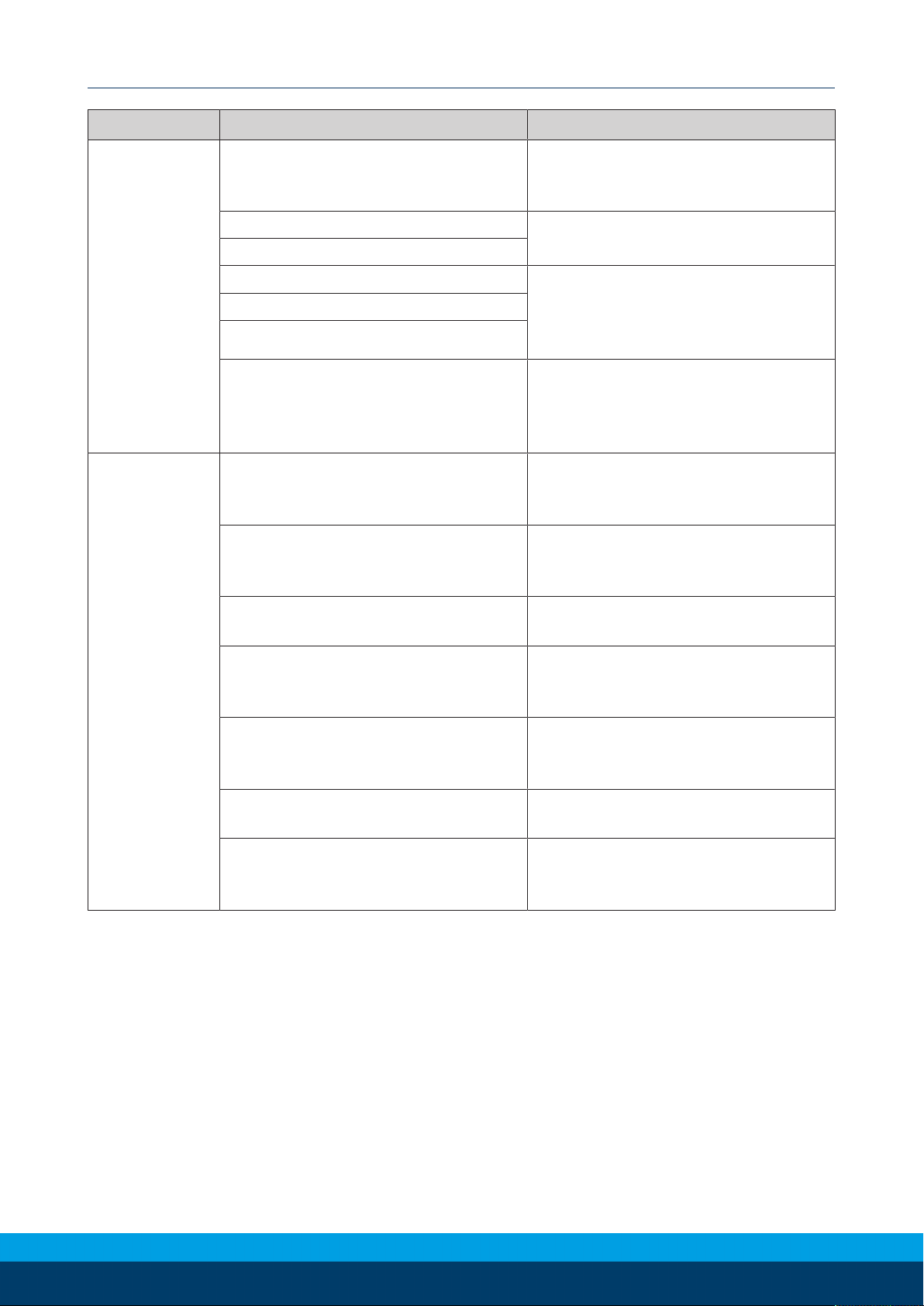
8.1 Errors with the URCap Software
Question/Problem Answer/Solution
After clicking Start Daemon on the
“SCHUNK Force/Torque Sensor screen
“during the URCap Software Setup, an er-
The SCHUNK F/T Sensor IP Address entered
may be incorrect. Verify the IP address and
reenter Setting up URCap Software [}14].
ror message “SCHUNK FT Daemon failed”
appears.
During operation, a “Protective Stop” error message appears.
There has been a loss of communication
between the sensor and the URCap software.
Verify that all cables are connected, and the
sensor is powered. Select the Enable Robot
button on the error message to re-establish
communication Protective Stop Error [}33].
The UR is not using data from an SCHUNK
F/T sensor that the user installed on the
Verify that the Enable command is selected
Program Node Commands [}26].
robot arm.
The URCap software is malfunctioning. Another method to review the activity of the
URCap software is to make sure a Logging Level
is set and reference the logging file for details
Logging Level [}29] and Section 4.3.2.2—Log-
ging File [}29].
The SCHUNK F/T AXIA80 sensor is mal-
Refer to the Ethernet AXIA manual.
functioning.
The SCHUNK NET F/T sensor is malfunctioning.
Refer to the NET FT manual.
44
01.00 | SCHUNK Software Module for URCap | Software Manual | en | 1369443
 Loading...