


CAUTION:
Read all Safety Rules and Operating Instructions,
and follow them with each use of this product.
00-99-000365/0408
OWNER’S MANUAL
Fully Automatic
Microprocessor Controlled
Battery Charger and
Maintainer with
Battery Tester
Model SSC-1500A
For 12-Volt Batteries
TM
®


• 1 •
IMPORTANT SAFETY INSTRUCTIONS1.
SAVE THESE INSTRUCTIONS – This manual contains important safety 1.1
and operating instructions for battery charger Model SSC-1500A.
Do not expose charger to rain or snow.1.2
Use of an attachment not recommended or sold by the battery charger 1.3
manufacturer may result in a risk of re, electric shock, or injury to persons.
To reduce risk of damage to electric plug and cord, pull by plug rather than 1.4
cord when disconnecting charger.
An extension cord should not be used unless absolutely necessary. Use of 1.5
improper extension cord could result in a risk of re and electric shock. If
an extension cord must be used, make sure:
That pins on plug of extension cord are the same number, size, and •
shape as those of plug on charger;
That extension cord is properly wired and in good electrical condition and;•
That wire size is large enough for AC ampere rating of charger as speci-•
ed in Table 8.3.
Do not operate charger with damaged cord or plug; take to a qualied 1.6
service person. (Call customer service at: 800-621-5485.)
Do not operate charger if it has received a sharp blow, been dropped, or 1.7
otherwise damaged in any way; take it to a qualied serviceman. (Call
customer service at: 800-621-5485.)
Do not disassemble charger; take it to a qualied serviceman when 1.8
service or repair is required. Incorrect reassembly may result in a risk of
electric shock or re. (Call customer service at: 800-621-5485.)
To reduce risk of electric shock, unplug charger from outlet before attempt-1.9
ing any maintenance or cleaning. Turning off controls will not reduce this
risk.
WARNING – RISK OF EXPLOSIVE GASES.
WORKING IN VICINITY OF A LEAD-ACID BATTERY IS DANGEROUS.
BATTERIES GENERATE EXPLOSIVE GASES DURING NORMAL
BATTERY OPERATION. FOR THIS REASON, IT IS OF UTMOST
IMPORTANCE THAT YOU FOLLOW THE INSTRUCTIONS EACH TIME
YOU USE THE CHARGER.
TO REDUCE RISK OF BATTERY EXPLOSION, FOLLOW THESE
INSTRUCTIONS AND THOSE PUBLISHED BY BATTERY MANUFACTURER AND MANUFACTURER OF ANY EQUIPMENT YOU INTEND TO
USE IN VICINITY OF BATTERY. REVIEW CAUTIONARY MARKING ON
THESE PRODUCTS AND ON ENGINE.
IMPORTANT: READ AND SAVE THIS SAFETY AND INSTRUCTION MANUAL.

• 2 •
PERSONAL PRECAUTIONS2.
Consider having someone close enough by to come to your aid when you 2.1
work near a lead-acid battery.
Have plenty of fresh water and soap nearby in case battery acid contacts 2.2
skin, clothing, or eyes.
Wear complete eye protection and clothing protection. Avoid touching 2.3
eyes while working near battery.
If battery acid contacts skin or clothing, wash immediately with soap and 2.4
water. If acid enters eye, immediately ood eye with running cold water for
at least 10 minutes and get medical attention immediately.
NEVER smoke or allow a spark or ame in vicinity of battery or engine.2.5
Be extra cautious to reduce risk of dropping a metal tool onto battery. It 2.6
might spark or short-circuit battery or other electrical part that may cause
explosion.
Remove personal metal items such as rings, bracelets, necklaces, and 2.7
watches when working with a lead-acid battery. A lead-acid battery can
produce a short-circuit current high enough to weld a ring or the like to
metal, causing a severe burn.
Use charger for charging a LEAD-ACID battery only. It is not intended to 2.8
supply power to a low voltage electrical system other than in a starter-motor application. Do not use battery charger for charging dry-cell batteries
that are commonly used with home appliances. These batteries may burst
and cause injury to persons and damage to property.
NEVER charge a frozen battery.2.9
PREPARING TO CHARGE3.
If necessary to remove battery from vehicle to charge, always remove 3.1
grounded terminal from battery rst. Make sure all accessories in the
vehicle are off, so as not to cause an arc.
Be sure area around battery is well ventilated while battery is being 3.2
charged.
Clean battery terminals. Be careful to keep corrosion from coming in con-3.3
tact with eyes.
Add distilled water in each cell until battery acid reaches level specied by 3.4
battery manufacturer. Do not overll. For a battery without removable cell
caps, such as valve regulated lead acid batteries, carefully follow manufacturer’s recharging instructions.
Study all battery manufacturer’s specic precautions while charging and 3.5
recommended rates of charge.
Determine voltage of battery by referring to vehicle owner’s manual and 3.6
make sure that output voltage selector switch is set at correct voltage. If
charger has adjustable charge rate, charge battery initially at lowest rate.

• 3 •
CHARGER LOCATION4.
Locate charger as far away from battery as DC cables permit.4.1
Never place charger directly above battery being charged; gases from bat-4.2
tery will corrode and damage charger.
Never allow battery acid to drip on charger when reading electrolyte spe-4.3
cic gravity or lling battery.
Do not operate charger in a closed-in area or restrict ventilation in any 4.4
way.
Do not set a battery on top of charger.4.5
DC CONNECTION PRECAUTIONS5.
Connect and disconnect DC output clips only after setting any charger 5.1
switches to “off” position and removing AC cord from electric outlet. Never
allow clips to touch each other.
Attach clips to battery and chassis, as indicated in 6.5, 6.6, and 7.2 5.2
through 7.4.
FOLLOW THESE STEPS WHEN BATTERY IS INSTALLED IN 6.
VEHICLE.
A SPARK NEAR BATTERY MAY CAUSE BATTERY EXPLOSION. TO
REDUCE RISK OF A SPARK NEAR BATTERY:
Position AC and DC cords to reduce risk of damage by hood, door, or 6.1
moving engine part.
Stay clear of fan blades, belts, pulleys, and other parts that can cause 6.2
injury to persons.
Check polarity of battery posts. POSITIVE (POS, P, +) battery post usually 6.3
has larger diameter than NEGATIVE (NEG, N,–) post.
Determine which post of battery is grounded (connected) to the chassis. 6.4
If negative post is grounded to chassis (as in most vehicles), see (6.5). If
positive post is grounded to the chassis, see (6.6).
For negative-grounded vehicle, connect POSITIVE (RED) clip from battery 6.5
charger to POSITIVE (POS, P, +) ungrounded post of battery. Connect
NEGATIVE (BLACK) clip to vehicle chassis or engine block away from
battery. Do not connect clip to carburetor, fuel lines, or sheet-metal body
parts. Connect to a heavy gauge metal part of the frame or engine block.
For positive-grounded vehicle, connect NEGATIVE (BLACK) clip from bat-6.6
tery charger to NEGATIVE (NEG, N, –) ungrounded post of battery. Connect POSITIVE (RED) clip to vehicle chassis or engine block away from
battery. Do not connect clip to carburetor, fuel lines, or sheet-metal body
parts. Connect to a heavy gauge metal part of the frame or engine block.

• 4 •
When disconnecting charger, turn switches to off, disconnect AC cord, 6.7
remove clip from vehicle chassis, and then remove clip from battery terminal.
See OPERATING INSTRUCTIONS for length of charge information.6.8
FOLLOW THESE STEPS WHEN BATTERY IS OUTSIDE VEHICLE. 7.
A SPARK NEAR THE BATTERY MAY CAUSE BATTERY EXPLOSION.
TO REDUCE RISK OF A SPARK NEAR BATTERY:
Check polarity of battery posts. POSITIVE (POS, P, +) battery post usually 7.1
has a larger diameter than NEGATIVE (NEG, N, –) post.
Attach at least a 24-inch-long 6-gauge (AWG) insulated battery cable to 7.2
NEGATIVE (NEG, N, –) battery post.
Connect POSITIVE (RED) charger clip to POSITIVE (POS, P, +) post of 7.3
battery.
Position yourself and free end of cable as far away from battery as pos-7.4
sible – then connect NEGATIVE (BLACK) charger clip to free end of cable.
Do not face battery when making nal connection.7.5
When disconnecting charger, always do so in reverse sequence of con-7.6
necting procedure and break rst connection while as far away from battery as practical.
A marine (boat) battery must be removed and charged on shore. To 7.7
charge it onboard requires equipment specially designed for marine use.
BATTERY CHARGING - AC CONNECTIONS8.
For all grounded cord-connected battery chargers:8.1
GROUNDING AND AC POWER CORD CONNECTION •
INSTRUCTIONS – Charger should be grounded to reduce risk of electric
shock. Charger is equipped with an electric cord having an equipmentgrounding conductor and a grounding plug. The plug must be plugged
into an outlet that is properly installed and grounded in accordance with
all local codes and ordinances.
DANGER – Never alter AC cord or plug provided – if it will not t outlet,
have proper outlet installed by a qualied electrician. Improper connection can result in a risk of an electric shock.
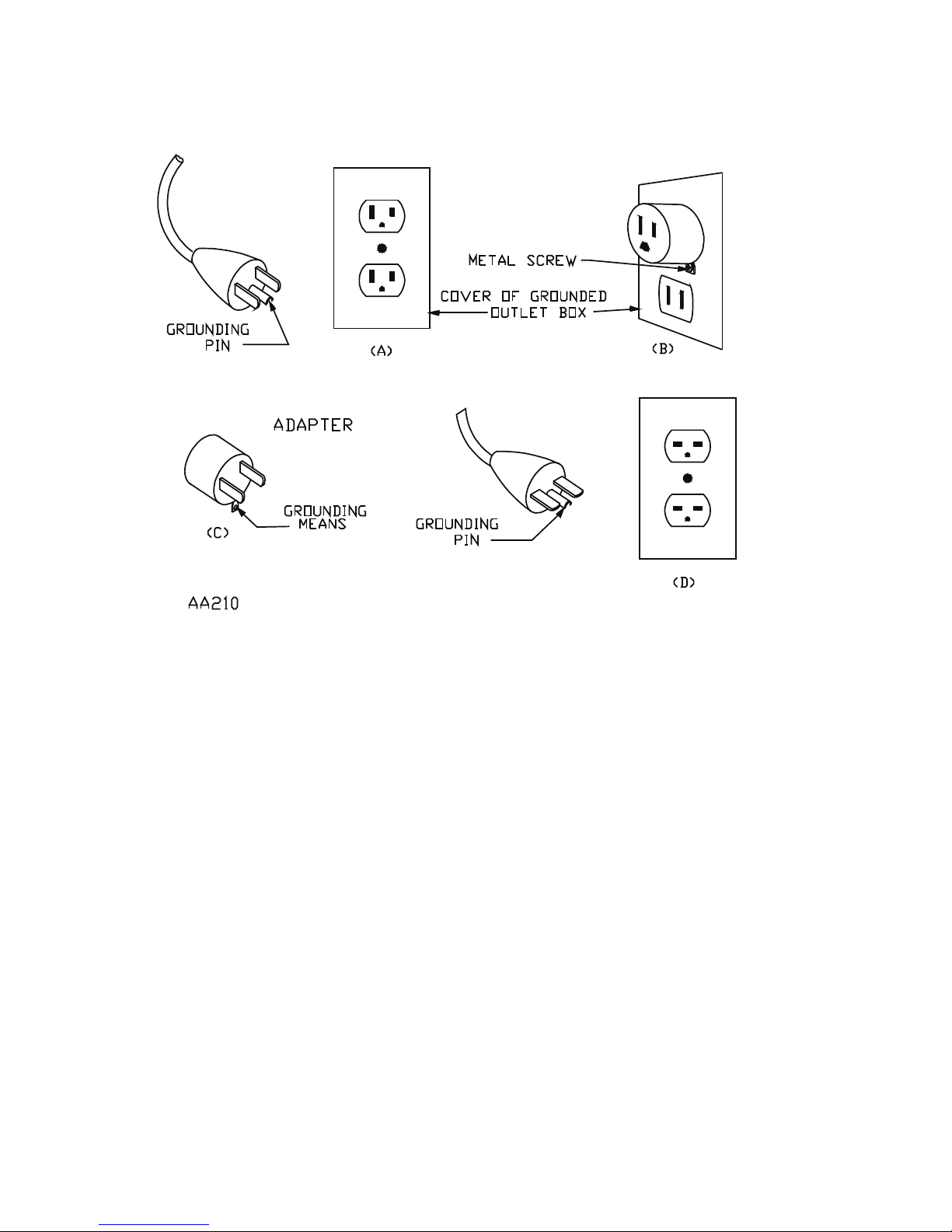
For grounded, cord-connected battery chargers with an input rating 8.2
less than 15 amperes and intended for use on a nominal 120-volt
circuit:
This battery charger is for use on a nominal 120-volt circuit, and has a •
grounding plug that looks like the plug illustrated in sketch A in Figure
8.4. A temporary adapter, which looks like the adapter illustrated in
sketches B and C, may be used to connect this plug to a two-pole receptacle as shown in sketch B if a properly grounded outlet is not available.
The temporary adapter should be used only until a properly grounded

• 5 •
outlet can be installed by a qualied electrician.
DANGER – Before using adapter as illustrated, be certain that center
screw of outlet plate is grounded. The green-colored rigid ear or lug ex
tending from adapter must be connected to a properly grounded outlet–
make certain it is grounded. If necessary, replace original outlet cover
plate screw with a longer screw that will secure adapter ear or lug to
outlet cover plate and make ground connection to grounded outlet.
8.3
25 50 100 150
(7.6) (15.2) (30.5) (45.6)
0 2 18 18 18 16
2 3 18 18 16 14
3 4 18 18 16 14
4 5 18 18 14 12
5 6 18 16 14 12
6 8 18 16 12 10
8 10 18 14 12 10
10 12 16 14 10 8
12 14 16 12 10 8
14 16 16 12 10 8
16 18 14 12 8 8
18 20 14 12 8 6
a
If the input rating of a charger is given in watts rather than in
amperes, the corresponding ampere rating is to be determined
by dividing the wattage rating by the voltage rating ± for
example:
1250 watts/125 volts = 10 amperes
Length of cord, feet (m)
AWG size of cord
AC input rating,
amperes
a
But less
than
At least
• 6 •
8.4
Grounding Methods
• 7 •
ASSEMBLY INSTRUCTIONS9.
No assembly required•
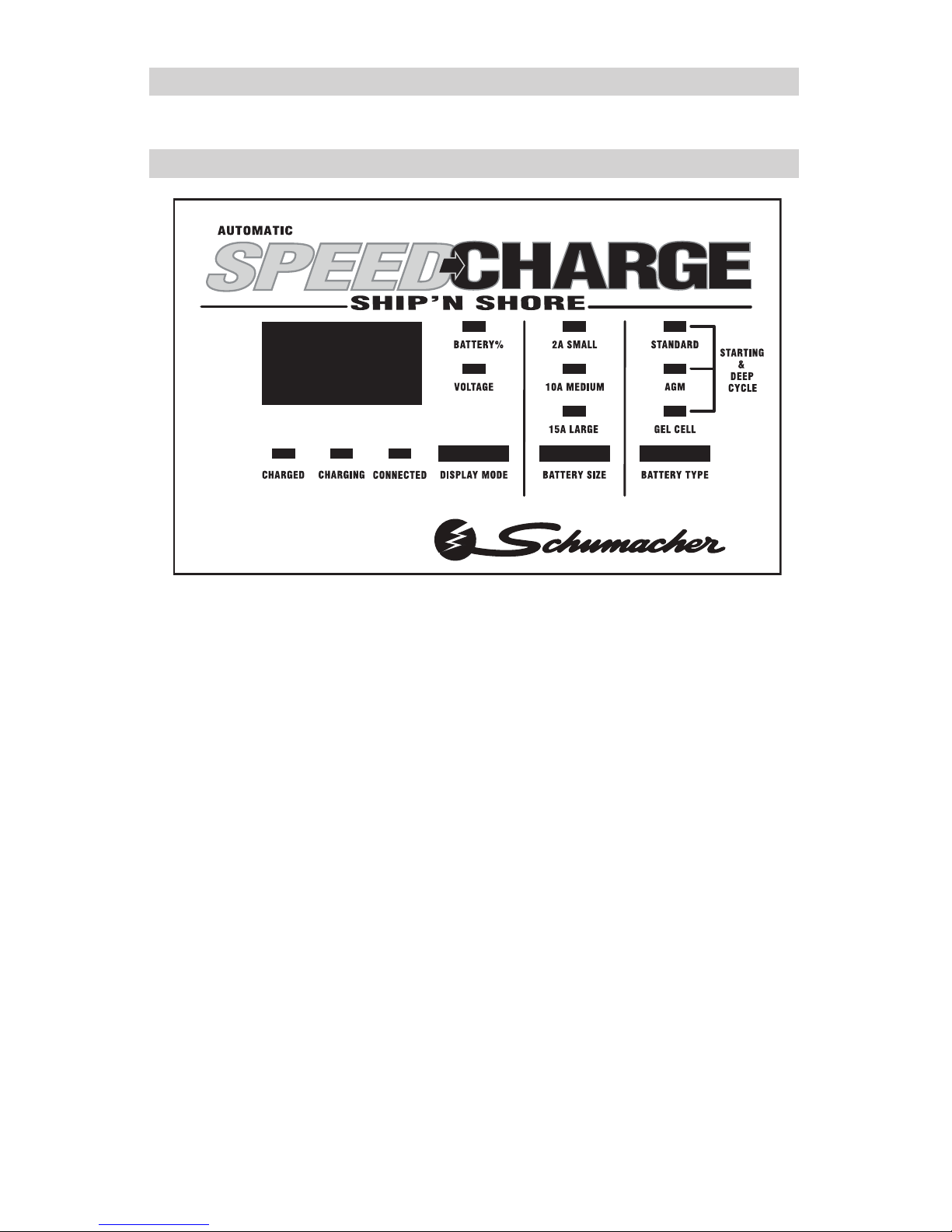
SPEEDCHARGE CONTROL10.
DISPLAY MODE SWITCH 10.1
Use this switch to set the function of the digital meter to one of the following:
BATTERY %: The digital meter displays an estimated percent of charge.
VOLTAGE: The digital meter displays the voltage in DC volts.
BATTERY SIZE SWITCH 10.2
Use this switch button to set the charge rate to one of the following three:
®
TM

• 8 •
2A SMALL: Intended for charging small batteries such as those commonly used in garden tractors, snow mobiles and motorcycles. The 2A rate is
not intended to be used as a trickle charger for larger batteries.
10A MEDIUM or 15A LARGE: Use for charging automotive batteries,
marine batteries, and deep cycle batteries. Not intended for industrial applications.
BATTERY TYPE BUTTON 10.3
Use this button to set the type of battery to be charged to one of the following three:
NOTE: Each of the three settings apply for regular and deep cycle batteries.
STANDARD: This is the type of battery usually used in cars, trucks, and
motorcycles. These batteries have vent caps and are often marked “low
maintenance” or “maintenance-free.”
AGM: AGM batteries have sealed cases without vent caps. Such batteries
are often smaller than the other types.
GEL CELL: Gel Cell batteries have sealed cases without vent caps. Such
batteries are often smaller than the other types.
With the exception of AGM and gel cell batteries, all other battery types
may or may not have vent caps. Vent caps are located on top of the bat-
tery and provide a means to add distilled water when needed. Batteries
should be marked with their type. If charging a battery that is not marked,
check the manual of the item that uses the battery. If the battery type is
unknown, use the STANDARD setting. Make sure the battery complies
with the safety instructions.

• 9 •
CONTROL PANEL GUIDE11.
SSC-1500A CONTROL PANEL GUIDE
MODE OF OPERATION
C
H
A
R
G
E
D
C
H
A
R
G
I
N
G
C
O
N
N
E
C
T
E
D
B
A
T
T
E
R
Y
%
V
O
L
T
A
G
E
2
A
S
M
A
L
L
1
0
A
M
E
D
I
U
M
1
5
A
L
A
R
G
E
S
T
A
N
D
A
R
D
A
G
M
G
E
L
C
E
L
L
Digital
Display
Initial power-up, battery not detected O O 0.0
No battery or reversed battery detected 0(%) or 0.0(V)
Battery tester activated O 0~100
Battery tester with charged battery O O O 100
Battery tester with no battery O 0
Voltage tester with no battery detected 0.0
Voltage tester with battery detected O 0.1~17.0
2 Amp charge with battery detected O O O xx(%) or xx.x(V)
10 Amp charge with battery detected O O O xx(%) or xx.x(V)
15 Amp charge with battery detected O O O xx(%) or xx.x(V)
Char
ge complete - Maintain Mode started O 100(%) or xx.x(V)
Desulfation mode activated B 15(%) or 16(V)
Charge aborted B *bad bat (B)
Empty spaces indicate LEDs that are off. B indicates an LED that blinks on and off. x indicates a digit 0 ~ 9.
O indicates an LED that is on continuously. * display blinks "bad" then "bat" repeatedly
User selected
User selected
User selected
User selected
User selected
User selected
User selected
User selected
User selected
User selected
User selecte
d
User selected
User selected
User selected
User selected User selected
User selected
User selected
 Loading...