

0099001902-02
MODEL / MODELO / MODÈLE :
SJ1332
Jump Starter and DC Power Source
Arrancador y Fuente de Poder de CC
Bloc d’alimentation et aide démarrage
OWNERS MANUAL / MANUAL DEL USUARIO
MANUEL D’UTILISATION
PLEASE SAVE THIS OWNERS MANUAL AND READ BEFORE EACH USE.
This manual will explain how to use the portable power safely and effectively.
Please read and follow these instructions and precautions carefully.
POR FAVOR CONSERVE ESTE MANUAL DEL USUARIO Y LEALO ANTES
DE CADA USO. En este manual le explica cómo utilizar la fuente de poder de
manera segura y conable. Por favor, lea y siga las siguientes instrucciones y
precauciones.
ESSAYER DE GARDER LE MANUEL D’INSTRUCTIONS ET LE LIRE AVANT
CHAQUE UTILISATION. Ce manuel explique comment utiliser l’unité d’une façon
sûre et efcace. S’il vous plaît lisez et suivez ces instructions et précautions.
• 2 •
1. IMPORTANT SAFETY INSTRUCTIONS
SAVE THESE INSTRUCTIONS.
WARNING – RISK OF EXPLOSIVE GASES
WORKING IN THE VICINITY OF A LEAD-ACID BATTERY IS DANGEROUS.
BATTERIES GENERATE EXPLOSIVE GASES DURING NORMAL OPERATION.
IT IS IMPORTANT THAT YOU FOLLOW THESE INSTRUCTIONS EACH TIME
YOU USE THE UNIT.
To reduce the risk of battery explosion, follow these instructions and those published by
the battery manufacturer and the manufacturer of any equipment you intend to use in the
vicinity of a battery. Review cautionary markings on these products and on the engine.
WARNING!
RISK OF ELECTRIC SHOCK OR FIRE.
1.1 Keep out of reach of children.
1.2 Do not disassemble the jump starter.
Take it to a qualied service professional
if service or repair is required. Incorrect
assembly may result in re or electrical
shock.
1.3 Do not use the jump starter to jump a
vehicle while charging the internal battery.
1.4 Do not recharge the jump starter with a
damaged extension cord.
1.5 The jump starter gets hot during charging
and must have proper ventilation.
1.6 Do not set the jump starter on ammable
materials, such as carpeting, upholstery,
paper, cardboard, etc.
1.7 Place the jump starter as far away from
the battery being jumped as the cables
will permit.
1.8 Do not expose the jump starter to rain
or snow.
1.9 Never attempt to jump start a frozen
battery.
1.10 Never place the jump starter directly
above battery being jumped.
1.11 To prevent arcing, never allow the clamps
to touch together or to contact the same
piece of metal.
1.12 Use of an attachment not recommended
or sold by Schumacher® Electric
Corporation may result in damage to the
unit or personal injury.
1.13 Never operate the jump starter if it is
damaged.
1.14 If someone else uses the jump starter,
ensure they are well informed on how
to use it safely, and have read and
understood the operating instructions.
1.15 The jump starter is NOT designed to be
installed as a replacement for a vehicle
battery.
1.16 Use ONLY on vehicles, boats and garden
tractors powered with a 12V DC battery
system.
1.17 If the engine fails to start after the
recommended number of attempts,
disconnect the unit and look for other
problems that may need to be corrected.
1.18 Use the jump starter for jump starting
lead-acid batteries only. Do not use for dry
cell batteries that are commonly used with
home appliances.
CONTAINS SEALED, NON-SPILLABLE LEAD-ACID BATTERY.
MUST BE DISPOSED OF PROPERLY.
CONTIENE UNA BATERÍA SELLADA DE ÁCIDO-PLOMO NO
DERRAMABLE QUE DEBE DESECHARSE APROPIADAMENTE.
CONTIENT UNE BATTERIE À L’ACIDE QUI DOIT ÊTREDISPOSÉ
CORRECTEMENT.
WARNING: Possible explosion hazard. Contact with battery acid may cause severe burns
and blindness. Keep out of reach of children.
ADVERTENCIA: Posible riesgo de una explosión. El contacto con una batería de ácido
puede causar quemaduras y ceguera. Manténgase alejado de los niños.
AVERTISSEMENT : Hasard d’explosion possible. Contact avec l’acide de batterie peut
provoquer sévère brûle et la cécité. Ne le laissez pas a la portée des enfants.
• 3 •
2. PERSONAL SAFETY PRECAUTIONS
2.1 Restrictions on Use:
The converter may not be used with life
support devices or systems. Failure of this
converter can reasonably be expected to
cause failure of that life support device
or system, or to affect the safety or
effectiveness of that device or system.
2.2 Wear complete eye protection and
protective clothing when working near
lead-acid batteries. Always have someone
nearby for help.
2.3 Have plenty of fresh water, soap and
baking soda nearby for use, in case battery
acid contacts your eyes, skin, or clothing.
Wash immediately with soap and water
and seek medical attention.
2.4 If battery acid comes in contact with eyes,
ush eyes immediately for a minimum 10
minutes and get medical attention.
2.5 Neutralize any acid spills thoroughly with
baking soda before attempting to clean up.
2.6 Remove all personal metal items from your
body, such as rings, bracelets, necklaces
and watches. A battery can produce a
short circuit current high enough to weld a
ring to metal, causing a severe burn.
2.7 Never smoke or allow a spark or ame in
the vicinity of the battery or engine.
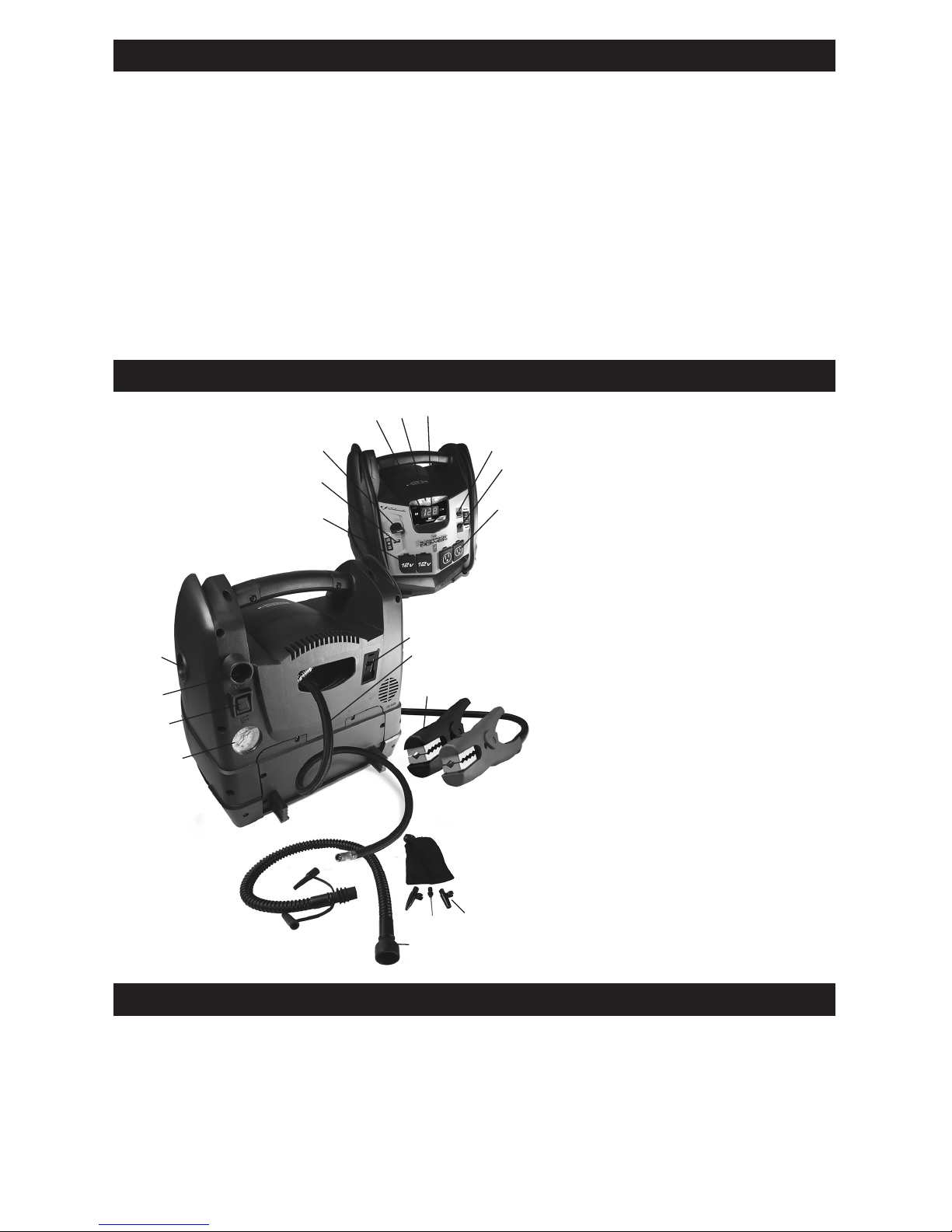
3. FEATURES
1. Compressor gauge
2. Compressor/inator switch
3. Inator port
4. Deator port
5. 12 Volt DC outlets
6. USB port
7. Jump start/USB On/Off switch
8. Digital display
9. Built-in work light
10. Display button
11. Work light On/Off switch
12. Converter On/Off switch
13. 120 Volt AC outlets
14. Charger port
15. Compressor hose
16. Battery clamps
17. Adapters
18. Inator hose
7
6
9
8
10
11
12
5
13
14
15
1
2
4
16
3
17
18
4. CHARGING THE INTERNAL BATTERY OF THE JUMP STARTER
IMPORTANT:
CHARGE IMMEDIATELY AFTER
PURCHASE, AFTER EACH USE AND
EVERY 30 DAYS, TO KEEP THE UNIT’S
INTERNAL BATTERY FULLY CHARGED
AND PROLONG BATTERY LIFE.
4.1 CHECKING THE LEVEL
OF THE INTERNAL BATTERY
Check the internal battery’s charge level
by pressing the Display Button. The Digital
Display will show the battery’s percent of
charge. Charge the internal battery if the
display shows it is under 100%.

• 4 •
NOTE: The internal battery’s percent
of charge is most accurate when the jump
starter has been disconnected from all
devices and charging sources
for a few hours.
4.2 CHARGING THE INTERNAL BATTERY
Charge the internal battery of the jump
starter using an extension cord (not
included).
NOTE: Use of an improper extension
cord could result in a risk of re and
electric shock.
1. Plug an extension cord into the charger
port on the back of the jump starter.
2. Plug the extension cord into a 120VAC
electrical wall outlet. While the jump
starter is connected to an AC outlet, the
green LED on the back of the unit will
be on.
3. Monitor the progress of the charge by
pressing the display button on the front
of the unit. When the internal battery is
fully charged, the display will show 100.
Complete charging may take up to 72
hours. The jump starter is then ready
to use.
4. When fully charged, the charger will
automatically go into maintain mode
and maintain the battery at full charge
without damaging it.
5. Charge the jump starter as soon as
possible after use.
4.3 CHARGING THE INTERNAL BATTERY
WHILE DRIVING
You may also charge the internal battery
while driving, using a male-to-male
charger cable (part number 94500109 –
not included).
IMPORTANT: DO NOT CHARGE
INTERNAL BATTERY FOR MORE THAN
30 MINUTES OR LEAVE THE BATTERY
UNATTENDED. IT COULD EXPLODE,
CAUSING PROPERTY DAMAGE OR
PERSONAL INJURY.
1. Make sure the car is running.
2. Insert one end of the accessory cable
into the 12V DC power outlet.
3. Insert the other end of the accessory
cable into the vehicle’s accessory outlet
(lighter socket).
NOTE: The GREEN LED does not
operate during this method of charging.
Using this method to charge the battery
overrides the maintain mode and the
battery can be overcharged.
4. Monitor the progress of the charge by
pressing the display button on the front
of the unit. When the battery is fully
charged, disconnect the accessory
cable from the jump starter, then from
the lighter socket of the vehicle.
NOTE: Completely disconnect the charger
cable when the engine is not running.
5. OPERATING INSTRUCTIONS
5.1 JUMP STARTING A VEHICLE
IMPORTANT: Using the Jump Start feature
without a battery installed in the vehicle will
damage the vehicle’s electrical system.
1. Turn the ignition OFF.
2. Lay the DC cables away from any
fan blades, belts, pulleys and other
moving parts.
3. For a negative-ground vehicle (as
in most vehicles), connect the unit’s
POSITIVE (RED) clamp to the
POSITIVE (POS, P, +) battery post.
Next, connect the NEGATIVE (BLACK)
clamp to the vehicle chassis or engine
block, away from the battery.
4. For a positive-ground vehicle, connect
the unit’s NEGATIVE (BLACK) clamp
to the NEGATIVE (NEG, N, -) battery
post. Next, connect the POSITIVE (RED)
clamp to the vehicle chassis or engine
block away from the battery.
5. Turn the switch to the ON position.
NOTE: When connected to the vehicle,
the display shows the vehicle’s battery
voltage. When connected and in the ON
position, the display shows the equalized
voltage between the vehicle’s battery and
internal battery.
6. Crank the engine for no more than 8
seconds. If the engine does not start,
wait 2 minutes before cranking again.
7. After the engine starts, turn the switch to
the OFF position and remove the jump
starter from the battery.
8. Charge the unit.
5.2 USING THE USB PORT
The USB port provides up to 2A at 5V DC.
1. Ensure the battery clamps are securely
clipped on the storage holders.
2. Turn the unit ON.
3. Plug your device into the USB port.
4. When nished using the USB port, turn
the switch to the OFF position.
5. Charge the unit.

• 5 •
5.3 USING THE WORK LIGHT
The work light is controlled by a sliding ON/
OFF switch located on the front of the unit.
• Make sure the lamp is turned OFF when
the unit is being recharged or stored.
• Position the unit on a at, stable surface
near the intended work area.
• Ensure the battery clamps are securely
clipped on the storage holders.
5.4 POWERING A 12V DC DEVICE
The unitis a power source for all 12V DC
accessories that are equipped with a 12V
accessory plug. Use it for power outages
and on shing or camping trips.
NOTE: Do not power a 12V device with
the unit while charging the internal battery.
1. Make sure the device to be powered
is OFF before inserting the 12V DC
accessory plug into the 12V DC
accessory outlet.
2. Open the protective cover of the DC
power outlet on the unit.
3. Plug the 12V DC device into the DC
power outlet and turn on the 12V DC
device (if required).
4. When nished, turn off the DC device
(if required) and unplug from the DC
power outlet.
CAUTION: Do not use the unit to run
appliances that draw more than 20A DC.
NOTE: Extended operation of a 12V DC
device may result in excessive battery
drain. Recharge the unit immediately after
unplugging the 12V DC device.
5.5 USING THE AIR COMPRESSOR
NOTE: To prevent overheating, the
compressor has built-in thermal protection
that will turn the compressor off before it
overheats. If the compressor shuts off,
wait a few minutes and it will automatically
restart when the compressor cools.
WARNING. Read the instructions of the
product being inated before using the
compressor. Avoid overination; do not
exceed the manufacturer’s recommended
pressures. Do not leave the air
compressor unattended during use.
1. Remove the air compressor hose from
the storage compartment.
2. Connect the adapter to the valve stem
by threading it onto the end. If necessary,
use one of the additional adaptors.
3. Turn ON the inator power switch and
inate to the desired pressure or fullness.
4. When the desired pressure is reached,
put the inator power switch to OFF,
open the thumb latch and remove the
connector from the valve stem.
5. Allow unit to cool.
6. Recharge the unit before storing.
NOTE: The air compressor is rated for
150 PSI maximum.
5.6 USING THE INFLATOR
RISK OF EXPLOSION.
Read instructions of the product being
inated before using the inator.
Avoid overination, do not exceed the
manufacturer’s recommended pressures.
Do not leave the inator unattended
during use.
1. Ensure the battery clips are securely
on the storage holders.
2. Attach the corrugated hose with end
adapter to the high-ow inator outlet
located near the Compressor/Inator
switch on the back of the unit.
3. The main accessory adapter attached
to the corrugated hose accommodates
up to 4 sizes. If another size is needed,
an additional adapter can be attached to
the end of the main accessory adapter.
4. Insert the adapter into the product to be
inated.
5. Push the Compressor/Inator switch to
the INFLATOR position and inate the
product.
6. When the product is inated to the
desired level, push the Compressor/
Inator switch to the OFF position and
remove the adapter.
Estimated time for inating
Vehicle tires 13-16" 6-24 minutes
Bike tires 1-3 minutes
Sports balls 30 seconds
These times are approximate. Use the air
compressor gauge to ensure the proper pressure
has been reached. Do not overinate.
5.7 USING THE DEFLATOR
1. Ensure the battery clips are securely
on the storage holders.
2. Attach the corrugated hose with the
end adapter to the high-ow deator
outlet, which is located on the side of
the unit.
3. The main accessory adapter attached
to the corrugated hose accommodates
up to 4 sizes. If another size is needed,
an additional adapter can be attached
to the end of the main accessory
adapter.
4. Insert the adapter into the item to be
deated.
5. Push the Compressor/Inator switch to
the INFLATOR position and deate the
item.

• 6 •
6. When the product is deated to the
desired level, push the Compressor/
Inator switch to the OFF position and
remove the adapter.
5.8 BEFORE USING THE CONVERTER
Important Safety Instructions:
1. Keep the unit well ventilated, in order to
properly disperse heat generated while
it is in use. Make sure there are several
inches of clearance around the top and
sides, and do not block the vents on
the back of the unit.
2. Make sure the unit is not close to any
potential source of ammable fumes or
clothing.
3. Keep the unit dry.
4. DO NOT allow the unit to come into
contact with rain or moisture.
5. DO NOT operate the unit if you, the
unit, the device being operated or any
other surfaces that may come in contact
with any power source are wet. Water
and many other liquids can conduct
electricity, which may lead to serious
injury or death.
6. Do not place the unit on or near heating
vents, radiators or other sources of
heat.
7. Do not place the unit in direct sunlight.
The ideal air temperature for operation
is between 50° and 80° F.
8. Do not use the converter near an open
engine compartment where fumes may
accumulate.
9. Do not modify the AC receptacles in
any way.
5.9 USING THE CONVERTER
It is important to know the continuous
wattage of the device you plan to use with
the converter. The unit must be used with
devices drawing 200 watts or less. If the
wattage is not marked on the device, use
only devices that draw less than 1.7 amps
of AC current.
Devices like TVs, fans or electric
motors require additional power to start
(commonly known as the “starting” or
“peak” power). The unit can supply a
momentary surge in wattage; however
even devices rated less than the
maximum 200 watts can exceed the
converter’s surge capability and cause an
automatic overload shutdown.
Do not use the converter with a product
that draws a higher wattage than the
converter can provide, as this may cause
damage to the converter and the product.
Make sure the device you are using is
compatible with a modied sine wave
converter.
CAUTION: Always run a test to establish
whether the converter will operate a
particular piece of equipment or device.
In the event of a power overload, the
converter is designed to automatically
shut down. This safety feature prevents
damaging the converter while testing
devices and equipment with the
200-watt range.
If powering more than one device, start
one device at a time to avoid a power
surge and/or converter overload. The
surge load of each device should not
exceed the converter’s Continuous
Operation wattage rate.
IMPORTANT: If you are using the
power converter to operate any
type of battery charger, monitor the
temperature of the battery charger for
about 10 minutes. If the battery charger
becomes abnormally warm, disconnect
it from the converter immediately.
You can use an extension cord from
the converter to the device without
signicantly decreasing the power being
generated by the converter. For best
operating results, the extension cord
should be 16 AWG (1.31 mm2) or larger
and no longer than 50 feet.
IMPORTANT: This converter uses a
modied sine waveform, which is not quite
the same as power company electricity.
For the following devices, we strongly
recommend that you use caution and
check the device’s manual to make sure it
is compatible with modied sine waveform.
1. Switch mode power supplies
2. Linear power supplies
3. Class 2 transformers
4. Line lter capacitors
5. Shaded pole motors
6. Fan motors
7. Microwave ovens
8. Fluorescent and high-intensity lamps
(with a ballast)
9. Transformerless battery chargers
Using the converter with any of these
devices may cause the device to run
warmer or overheat.
POWERING A 120V AC DEVICE
1. Ensure the battery clips are securely
on the storage holders.
2. Open the protective cover of the AC
power outlet on the front panel of the unit.
3. Make sure the 120V AC device to be
operated is turned OFF.
4. Plug the 120V AC device into the AC
power outlet, and turn the converter
switch to the ON position. NOTE:
When the converter is turned on and
being used, the display will show the

• 7 •
total wattage used by the device being
powered by the converter.
5. Turn the device on.
6. If the device does not operate properly
when rst connected to the converter,
push the converter rocker switch ON,
OFF, and ON again in quick succession.
If this procedure is not successful, it is
likely that the converter does not have
the required capacity to operate the
device intended.
7. Charge the unit as soon as possible
after each use.
RISK OF ELECTRIC SHOCK.
Incorrect operation of your converter may
result in damage and personal injury.
The converter output is 120V AC and can
shock or electrocute the same as any
ordinary household AC wall outlet.
NOTE: The maximum continuous load is
200 watts. Do not use the converter with a
product that draws more than 200 watts,
as this may cause damage to the converter
and the product.
6. MAINTENANCE INSTRUCTIONS
6.1 After use and before performing
maintenance, unplug and disconnect
the jump starter.
6.2 Use a dry cloth to wipe all battery corrosion
and other dirt or oil from the battery clips,
cords and the jump starter case.
6.3 Ensure that all of the jump starter
components are in place and in good
working condition.
6.4 All servicing should be performed by
qualied service personnel.
7. MOVING AND STORAGE INSTRUCTIONS
7.1 Store inside, in a cool, dry place.
7.2 Do not store the clips on the handle,
clipped together, on or around metal, or
clipped to cables. The clips on the jump
starter are live when the switch is in the
ON position and will produce arcing or
sparking if they come in contact with each
other. To prevent accidental arcing, always
place the switch in the OFF position and
keep the clips on the storage holders when
not using it to jump start a vehicle.
7.3 If the jump starter is moved around the
shop or transported to another location,
take care to avoid/prevent damage to the
cords, clips and jump starter. Failure to
do so could result in personal injury or
property damage.
IMPORTANT: Do not use and/or store the
jump starter in or on any area or surface
where damage could occur if the internal
battery should unexpectedly leak acid.
7.4 IMPORTANT:
• CHARGE IMMEDIATELY AFTER
PURCHASE
• KEEP FULLY CHARGED
Charge the jump starter’s internal battery
immediately after purchase, after every
use and every 30 days.
All batteries are affected by temperature. The
ideal storage temperature is at 70°F. The
internal battery will gradually self-discharge
(lose power) over time, especially in warm
environments. Leaving the battery in a
discharged state may result in permanent
battery damage. To ensure satisfactory
performance and avoid permanent damage,
charge the internal battery every month.
8. TROUBLESHOOTING
PROBLEM POSSIBLE CAUSE SOLUTION
The unit won’t jump
start my car.
Jump Start/USB switch is not
turned ON.
Clips are not making a good
connection to the battery.
The internal battery is not charged.
The vehicle’s battery is defective.
Turn ON the Jump Start/USB
Switch.
Check for poor connection to
battery and frame. Make sure
connection points are clean. Rock
clamps back and forth for a better
connection.
Check the battery charge status
by pressing the button on the front
of the unit. See Checking the Level
of the Internal Battery.
Have the battery checked.

• 8 •
PROBLEM POSSIBLE CAUSE SOLUTION
The unit won’t power
my 12V device.
The 12V device is not turned on.
The internal battery is not
charged.
The 12V device draws more
than 20A, has a short circuit, or
the internal fuse has blown.
Turn on the 12V device.
Check the battery charge status by
pressing the button on the front of
the unit. See Checking the Level of
the Internal Battery.
Disconnect the 12V device.
The internal 20A fuse needs
replacement by a qualied
service person.
The battery in the unit
won’t hold a charge.
The battery is bad (will not
accept a charge).
Have the battery checked.
9. BEFORE RETURNING FOR REPAIRS
If these solutions do not eliminate the problem,
or for more information about troubleshooting,
contact customer service for assistance:
services@schumacherelectric.com
www.batterychargers.com
or call 1-800-621-5485
For REPAIR OR RETURN, contact Customer Service at 1-800-621-5485.
DO NOT SHIP UNIT until you receive a RETURN MERCHANDISE AUTHORIZATION
(RMA) number from Customer Service at Schumacher Electric Corporation.
10. SPECIFICATIONS
Internal Battery Type .....................................Sealed, Maintenance Free, AGM, Lead-Acid
Nominal Voltage ......................................................................................................12V DC
DC Power Output (Maximum Continuous Load).................... 20A (both outlets combined)
Jumper Cables ..................................................................................................4 AWG, 24˝
Dimensions (H x W x D)......................................................................... 12” x 11.5” x 10.5”
Weight ................................................................................................... 23.9 lbs (10.84 kg)
AC Power Specications
Maximum continuous power ............................................................................... 200 Watts
Surge capacity (peak power) .............................................................................. 400 Watts
No load current draw.......................................................................................... <0.4 Amps
Wave form .............................................................................................Modied sine wave
Input voltage range ...................................................................................10.5 – 15.5V DC
AC outlets .......................................................................(2) 120V AC 3-prong NEMA 5-15

• 9 •
11. REPLACEMENT PARTS
Air compressor accessory kit (3 hose adapters) ....................................... 2299001425Z
Inator accessory kit: (inator/deator hose, unit end, 3 hose adapters) ..... 0099000598Z
12. ACCESSORIES
Male-to-male accessory cable ........................................................................ 94500109
SPUSB 2.0 Amp dual USB 12V plug .............................................................. 94500750
13. LIMITED WARRANTY
WARRANTY NOT VALID IN MEXICO.
SCHUMACHER ELECTRIC CORPORATION, 801 BUSINESS CENTER DRIVE,
MOUNT PROSPECT, IL 60056-2179, MAKES THIS LIMITED WARRANTY TO THE
ORIGINAL RETAIL PURCHASER OF THIS PRODUCT. THIS LIMITED WARRANTY
IS NOT TRANSFERABLE OR ASSIGNABLE.
Schumacher Electric Corporation (the “Manufacturer”) warrants this Instant Power for
one (1) year and the internal battery for ninety (90) days from the date of purchase at
retail against defective material or workmanship that may occur under normal use and
care. If your unit is not free from defective material or workmanship, Manufacturer’s
obligation under this warranty is solely to repair or replace your product, with a new or
reconditioned unit, at the option of the Manufacturer. It is the obligation of the purchaser
to forward the unit, along with proof of purchase and mailing charges prepaid to the
Manufacturer or its authorized representatives in order for repair or replacement to occur.
Manufacturer does not provide any warranty for any accessories used with this product
that are not manufactured by Schumacher Electric Corporation and approved for use
with this product. This Limited Warranty is void if the product is misused, subjected to
careless handling, repaired, or modied by anyone other than Manufacturer or if this
unit is resold through an unauthorized retailer.
Manufacturer makes no other warranties, including, but not limited to, express, implied or
statutory warranties, including without limitation, any implied warranty of merchantability
or implied warranty of tness for a particular purpose. Further, Manufacturer shall
not be liable for any incidental, special or consequential damage claims incurred by
purchasers, users or others associated with this product, including, but not limited to,
lost prots, revenues, anticipated sales, business opportunities, goodwill, business
interruption and any other injury or damage. Any and all such warranties, other than the
limited warranty included herein, are hereby expressly disclaimed and excluded. Some
states do not allow the exclusion or limitation of incidental or consequential damages or
length of implied warranty, so the above limitations or exclusions may not apply to you.
This warranty gives you specic legal rights and it is possible you may have other rights
which vary from this warranty.
THIS LIMITED WARRANTY IS THE ONLY EXPRESS LIMITED WARRANTY AND THE
MANUFACTURER NEITHER ASSUMES OR AUTHORIZES ANYONE TO ASSUME
OR MAKE ANY OTHER OBLIGATION TOWARDS THE PRODUCT OTHER THAN
THIS WARRANTY.
Schumacher® and the Schumacher logo are registered trademarks
of Schumacher Electric Corporation.
 Loading...