

Page 1

OWNER’S MANUAL
SpeedCharge
™
computer
smart
™
2
a m p
S L O W
C H A R G E
12
30
a m p
F A S T
C H A R G E
75
a m p
E N G I N E
S T A R T
Model SC-7500A
For 6 and 12-Volt Batteries
Fully Automatic
Microprocessor Controlled
Battery Charger with
Engine Starter
CAUTION:
Read all Safety Rules and Operating Instructions,
and follow them with each use of this product.
Schumacher Electric Corporation
Mount Prospect, IL 60056 U.S.A.
Send Warranty Product Repairs to:
Customer Service Returns
P.O. Box 280,1025 E. Thompson, Hoopeston, IL 60942-0280
Questions? Call Customer Service: 1-800-621-5485
0099000621/0206
Page 2

TABLE OF CONTENTS
IMPORTANT SAFETY INSTRUCTIONS ................................................................... 3
PERSONAL SAFETY PRECAUTIONS ...................................................................... 4
BEFORE USING YOUR BATTERY CHARGER ........................................................ 5
Plugging It In ......................................................................................................... 5
Assembling Your Charger ..................................................................................... 5
Using An Extension Cord ...................................................................................... 5
PREPARING YOUR BATTERY TO BE CHARGED .................................................. 5
OPERATING INSTRUCTIONS ................................................................................... 6
Charging Battery In The Vehicle ........................................................................... 6
Charging Battery Removed From The Vehicle ..................................................... 7
Using Engine Start ................................................................................................ 7
USING YOUR BATTERY CHARGER ........................................................................ 8
CHARGER CONTROLS ............................................................................................. 9
CONTROL PANEL GUIDE ....................................................................................... 10
USING THE BUILT-IN BATTERY TESTER ..............................................................11
USING THE BUILT-IN ALTERNATOR TESTER ....................................................... 12
BATTERY PERCENT AND CHARGE TIME ............................................................ 13
CHARGING TIPS ...................................................................................................... 14
MAINTENANCE AND CARE ................................................................................... 14
TROUBLESHOOTING .............................................................................................. 15
WARRANTY .............................................................................................................. 16
PLEASE SAVE THIS OWNER’S MANUAL AND READ BEFORE EACH USE.
Model SC-7500A Microprocessor Controlled, Fully Automatic Operation Battery Charger
with Engine Starter Plus Battery and Alternator Tester offers features to accommodate
the needs for home or light commercial use. This manual will explain how to use the
battery charger safely and effectively. Please read and follow these instructions and
precautions carefully.
2
Page 3

IMPORTANT SAFETY INSTRUCTIONS
WARNING – RISK OF EXPLOSIVE GASES
WORKING IN VICINITY OF A LEAD-ACID BATTERY IS DANGEROUS. BATTERIES GENERATE EXPLOSIVE GASES DURING NORMAL BATTERY
OPERATION. FOR THIS REASON, IT IS OF UTMOST IMPORTANCE THAT
EACH TIME BEFORE USING YOUR CHARGER, YOU READ THIS MANUAL
AND FOLLOW THE INSTRUCTIONS EXACTLY.
To reduce risk of battery explosion, follow these instructions and those published by
battery manufacturer and manufacturer of any equipment you intend to use in vicinity of
battery. Review cautionary markings on these products and on engine.
SAVE THESE INSTRUCTIONS
This manual contains important safety and operating instructions for battery charger
model SC-7500A.
• WARNING: Handling the cord on this
product or cords associated with accessories sold with this product, may
expose you to lead, a chemical known
to the State of California to cause
cancer and birth defects or other
reproductive harm. Wash hands after
handling.
• Read all instructions and cautions
printed on the battery charger, battery,
and vehicle or equipment using battery.
• Use charger only on lead-acid type
rechargeable batteries, such as those
used in cars, trucks, tractors, airplanes, vans, RVs, trolling motors, etc.
This charger is not intended to supply
power to a low voltage electrical
system other than in a starter-motor
application.
• Never use charger for charging dry
cell batteries that are commonly used
with home appliances like radios, stereos, remote controls, etc. These batteries may burst and cause personal
injury.
• Do not disassemble charger. Take it
to a qualied service professional if
service or repair is required. Incorrect
assembly may result in re or electrical shock.
• To reduce risk of electrical shock,
unplug the charger from the outlet
before attempting any maintenance or
cleaning.
• Always charge battery in a well-ventilated area.
• WARNING: Battery chargers get hot
during operation and must have proper
ventilation. Air needs to ow around
entire charger. Do not set charger on
ammable materials like carpeting,
upholstery, paper, cardboard, etc.
Charger may damage leather and melt
plastic and rubber.
HELP US HELP YOU ——
Remember:
Place charger as far away from the battery being charged as the charger cables
will permit.
Do not expose charger to rain or snow.
Never charge a frozen battery. If battery
uid (electrolyte) becomes frozen, bring
battery into a warm area to thaw before
you begin charging.
Never allow battery acid to drip on char-
ger when reading specic gravity or lling
battery.
Never set a battery on top of the charger.
3
Page 4

Never place charger directly above battery
being charged. The gases from the battery
will corrode and damage the charger.
Never touch the battery clamps together
when the charger is on. You could cause
a spark.
Never operate charger if it has received
a hard blow, been dropped, or otherwise
damaged. Take it to a qualied professional
for inspection and repair.
Be sure to position the charger power cord
PERSONAL SAFETY PRECAUTIONS
to prevent it from being stepped on, tripped
over, or damaged.
Never pull out the plug by the cord when
unplugging the charger. Pulling on the
cord may cause damage to the cord or
the plug.
Do not operate the charger if it has a
damaged power cord or plug. Have the
cord replaced.
• Wear complete eye and clothing
protection when working with leadacid batteries.
• Make sure that someone is within
range of your voice to come to your
aid if needed while you work with or
are near a lead-acid battery.
• Have plenty of fresh water and soap
nearby for use in case battery acid
contacts your eyes, skin, or clothing. If
this happens, wash immediately with
soap and water. Then get medical attention.
• Avoid touching your eyes while
working with a battery. Acid particles
(corrosion) may get into your eyes. If
this occurs, ush eyes immediately
with running cold water for at least 10
minutes. Then immediately get medical attention.
• Remove all personal metal items
from your body such as rings, bracelets, necklaces and watches, while
working with a lead-acid battery. A battery can produce a short circuit current
high enough to weld a ring (or the like)
to metal, causing a severe burn.
• Take care not to drop any metal tool
or metal object onto the battery. This
may spark or short circuit the battery
or another electrical device that may
cause an explosion.
• Always operate the battery charger in
an open, well-ventilated area.
• Never smoke or allow a spark or ame
in the vicinity of the battery or engine.
Batteries generate explosive gases.
• Neutralize any acid spills thoroughly
with baking soda before attempting to
clean up.
4
Page 5
BEFORE USING YOUR BATTERY CHARGER
It is important to understand your charger's requirements. This section will tell you about
your charger's electrical requirements and how to prepare a battery for charging.
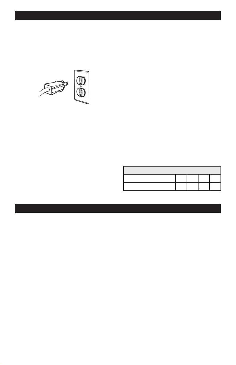
PLUGGING IT IN
Your charger requires a 120V AC 2-prong
wall outlet receptacle installed according
to all local codes and ordinances.
ASSEMBLING YOUR CHARGER
Included with your battery charger are two
cord wrap cleats for storage of the clamp
cables.
To install, align the two tabs to correspond
with the two receptacles and push until you
hear a snap.
Wrap clamp cables after unplugging the
power cord from the AC wall outlet and
store your charger in a dry location.
USING AN EXTENSION CORD
The use of an extension cord is not recommended. If you must use an extension
cord, please make sure that you follow
these guidelines:
• Make sure that the pins on charger's
power cord t rmly into the extension
cord, and that the extension cord ts
rmly into the receptacle.
• Check that the extension cord is properly
wired and in good electrical condition.
• Make sure that the wire size is large
enough for its length and for the AC
ampere rating, as specied in the chart
below.
MINIMUM RECOMMENDED EXTENSION CORD
Length of Cord, in Feet 25 50 100 150
AWG* Size of Cord 18 16 12 10
*AWG=American Wire Gauge
PREPARING YOUR BATTERY TO BE CHARGED
It is important that you read and follow these guidelines while you are preparing to charge
the battery.
• Make sure that you have a 6 or 12 volt
lead-acid battery. Determine voltage of
battery by referring to vehicle owner’s
manual or the battery markings. Charge
battery initially at charger’s lowest rate.
• Clean the battery terminals. Be careful to
keep corrosion from getting in or around
your eyes or on your hands.
• Wear safety glasses. See additional “Personal Safety Precautions” on page 4.
• If required, for batteries with removable
vent caps, add distilled water to each cell
until the battery acid reaches the level
recommended by the manufacturer. This
will help purge excessive gases from the
cells. Be careful not to overll. If you have
a sealed battery with non-removable vent
caps, no action is necessary.
• Take time to read all of the battery
manufacturer ’s specific precautions,
such as removing or not removing vent
caps while charging, and recommended
rates of charge.
• Be sure that the area around the battery is well ventilated while it is being
charged. Gas can be forcefully blown
away by using a piece of cardboard or
other nonmetallic material as a fan.
• If it is necessary to remove the battery
from the vehicle to charge it, always
remove the grounded terminal from the
battery rst. Turn off all vehicle accessories to avoid sparks from occurring.
• NOTE: A marine (boat) battery installed
in a boat must be removed and charged
on shore.
5
Page 6
OPERATING INSTRUCTIONS
NOTE: A marine (boat) boat battery must be removed and charged on shore. To charge
it on board requires equipment specially designed for marine use.
IMPORTANT: Follow all safety instructions and precautions when charging your battery.
Wear complete eye protection and clothing protection. Charge your battery in a wellventilated area.
CHARGING BATTERY IN THE
VEHICLE:
1. Avoid personal injury by keeping clear
of fan blades, belts, pulleys and other
engine parts.
2. Avoid damaging the charger by keeping the power cord and output cords
away from the hood, door or moving
engine parts.
3. Note the polarity of the battery posts
by checking the identication marks
on the battery: POSITIVE (POS, P or
+) and NEGATIVE (NEG, N or -). The
positive post is usually larger than the
negative post.
4. Identify which battery post is grounded or connected to the chassis. THIS
IS NORMALLY THE NEGATIVE
POST.
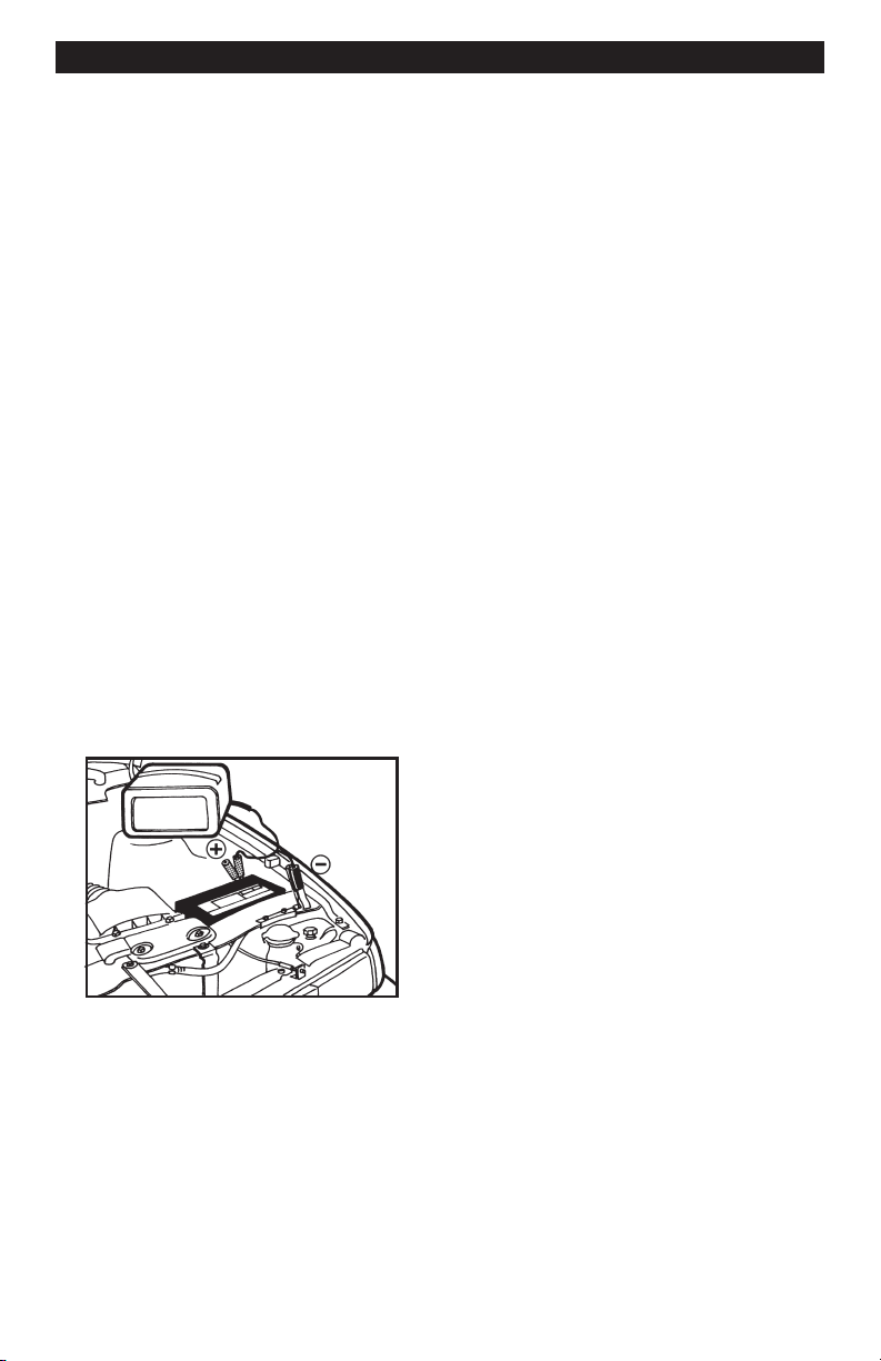
NEGATIVE GROUNDED SYSTEM
5. Connecting to a negative-grounded
system: Connect the red (POSITIVE)
output clamp to the POSITIVE post of
the battery. Rock and twist the clamp
back and forth to be sure a solid
electrical connection is made. Then
connect the black (NEGATIVE) output
clamp to a heavy, unpainted metal
part of the chassis or engine block,
away from the battery (see gure).
DO NOT connect clamp to negative
battery post, carburetor, fuel line or
sheet metal part.
Connecting to a positive-grounded
system: Connect the black (NEGATIVE) output clamp to the NEGATIVE
post of the battery. Rock and twist
the clamp back and forth to be sure
a solid electrical connection is made.
Then connect the red (POSITIVE)
output clamp to a heavy, unpainted
metal part of the chassis or engine
block, away from the battery. DO NOT
connect clamp to positive battery
post, carburetor, fuel line or sheet
metal part.
6. Plug power cord into a 120V AC
2-prong wall outlet. The charger will
be set to the default state of 12V
REGULAR battery type, no charge
rate (tester mode).
7. Press the appropriate control buttons
to select the desired charge rate and
battery type. Within a few seconds,
the CHARGING (yellow) LED should
light and the charging process should
start. If the CHECK (red) LED is on,
check for correct cable connections.
8. To disconnect the charger, unplug
its power cord before attempting to
disconnect the output clamps. Then,
standing away from the battery, remove the output clamp from the chassis or engine block. Finally, remove
the output clamp from the battery
post.
9. Clean and store the charger in a dry
location.
6
Page 7

CHARGING BATTERY REMOVED
FROM THE VEHICLE:
POSITIVE
BATTERY
24", 6 GAUGE CABLE
NEGATIVE
BATTERY
CHARGER
POWER
CORD
TO
GROUNDED
POWER
OUTLET
1. Note the polarity of the battery posts by
checking the identication marks on the
battery: POSITIVE (POS, P or +) and
NEGATIVE (NEG, N or -). The positive
post is usually larger than the negative
post.
2. Attach at least a 24-inch-long, 6-gauge
(AWG), insulated batter y cable to
NEGATIVE (NEG, N or -) battery post.
Rock and twist the clamp back and forth
to be sure a solid electrical connection
is made.
3. Connect the red (POSITIVE) output
clamp to the POSITIVE battery post.
Rock and twist the clamp back and forth
to be sure a solid electrical connection
is made.
4. Position yourself as far away from the
battery as possible, and then connect
the black (NEGATIVE) output clamp to
the free end of the cable.
5. Plug the power cord into a 120V AC
2-prong wall outlet. The charger will be set
to the default state of 12V REGULAR bat-
tery type, no charge rate (tester mode).
6. Press the appropriate control buttons
to select the desired charge rate and
battery type. Within a few seconds, the
CHARGING (yellow) LED should light
and the charging process should start.
If the CHECK (red) LED is on, check for
correct cable connections.
7. To disconnect the charger, unplug its
power cord before attempting to disconnect the charger clamps. Then, standing
away from the battery, remove the output clamp from the NEGATIVE battery
post. Finally, remove the output clamp
from the POSITIVE battery post.
8. Clean and store the charger in a dry
location.
USING ENGINE START
Your battery charger can be used to jump
start your car if the battery is low. Follow these instructions on how to use the
ENGINE START feature.
IMPORTANT: Follow all safety instructions
and precautions when charging your battery. Wear complete eye protection and
clothing protection. Charge your battery
in a well-ventilated area.
IMPORTANT: Using the ENGINE START
feature WITHOUT a battery installed in
the vehicle could cause damage to the
vehicle’s electrical system.
1. For battery connections, see page 6 and
follow instructions 1 – 6 of CHARGING
BATTERY IN THE VEHICLE. With the
charger plugged in and connected to the
battery of the vehicle, set the CHARGE
RATE to 75A START. Only the 75A
START, CHARGING, and VOLTAGE
LEDs should be lit, unless the 6V
REGULAR battery type has been selected. In that case, the 6V REGULAR
LED will also be lit.
2. Crank the engine for no more than 5
seconds. If engine does not start, wait
3 minutes before cranking again.
3. After the engine starts, unplug the power
cord before disconnecting the output
clamps from the battery.
4. Clean and store the charger in a dry
location.
NOTE: During the starting sequence listed
above, the charger is set to one of three
states.
1. Wait for cranking - The charger waits
until the engine is actually being cranked
before delivering 75 amps for engine
start. The charger delivers charge at a
rate of up to 12 amps while waiting and
will reset if the engine is not cranked
within 5 minutes. (If the charger resets,
it sets itself for a 2A charge and 12V
REGULAR battery.) While waiting for
cranking, the digital display shows
the battery voltage (it can’t be set to
percent).
2. Cranking - When cranking is detected,
the charger will automatically deliver
up to its maximum output (at least75A)
as required by the starting system for
7
Page 8

up to 5 seconds or until the engine
cranking stops. The digital display
shows a countdown of the remaining
crank time in seconds. It starts at 5 and
counts down to 0.
3. Cool Down - After cranking, the char-
ger enters a mandatory 3-minute (180
second) cool down state. During this
period, no settings can be changed.
The buttons are ignored. The digital
display indicates the remaining cool
down time in seconds. It starts at 180
and counts down to 0. The 75A START
LED blinks once every second. During
USING YOUR BATTERY CHARGER
the cool down period, no current is delivered to the battery. After 3 minutes,
the 75A START LED will stop blinking
and will light continuously, indicating that
another crank cycle can be started. The
digital display will change from displaying the countdown back to displaying
the battery voltage. The CHARGING
LED will then be lit.
ENGINE STARTING NOTES:
• If the battery is disconnected during
the cool down period, the charger will
reset.
OVERVIEW
Using this battery charger is very simple.
First, connect the battery and AC power
following the precautions listed under
“OPERATING INSTRUCTIONS”. Then
select the appropriate BATTERY TYPE
and CHARGE RATE for your battery. The
charger will then do everything automatically. This section explains a few details.
CHARGI NG: If the charger does not
detect a properly connected battery, the
CHECK (red) LED will light continuously
until such a battery is detected. Charging
will not begin while the CHECK LED is on.
When charging begins, the CHARGING
LED will be lit.
AUTOMATIC SHUT OFF: When the 2A,
12A 30A charge rate is selected, the
charger is set to perform an automatic
charge. When an automatic charge is
performed, the charger stops charging automatically after the battery is charged.
ABORTED CHARGE: If charging can’t
be completed normally, charging will be
aborted. When charging is aborted, the
charger’s output is shut off and the red
CHECK LED and digital display blink on
and off (at opposite times). In that state, the
charger ignores all buttons. To reset from
after an aborted charge, either disconnect
the battery or unplug the charger.
DESULFATION MODE: If a battery is
left discharged for an extended period,
it could become sulfated and not accept
a normal charge. If the charger detects a
sulfated battery, the charger will switch to
a special mode of operation designed for
such batteries. Activation of the special
desulfation mode is indicated by blinking
the CHARGING LED. If successful, normal charging will resume after the battery
is desulfated. The CHARGING LED will
then stop blinking and light continuously.
Desulfation could take up to 10 hours. If
desulfation fails, charging will be aborted
and the CHECK (red) LED will blink.
C O MP L E T IO N O F C H A R G I N G :
Cha r g e com p l e tion is in dicated by
the CH A RGED (green) LE D; wh en
lit, the charger has stopped charging
and switched to the Maintain Mode of
operation.
MAINTAIN MODE: When the CHARGED
(green) LED is lit, the charger has started
Maintain Mode. This mode of operation is
also known as Float-Mode Monitoring. In
this mode, the charger keeps the battery
fully charged by delivering a small amount
of current, when necessary. The voltage
is maintained at a level determined by the
BATTERY TYPE selected.
GENERAL CHARGING NOTES:
The charger is designed to control its
cooling fan for efcient operation. Consequently, it is normal for the fan to start
and stop when maintaining a fully charged
battery. The fan does not run in Tester
Mode.
8
Page 9

If the charge mode is changed after charg-
ing has started (by pressing the CHARGE
RATE or BATTERY TYPE button), the
charging process will be restarted.
CHARGER CONTROLS
The voltage displayed during charging is
the charging voltage and usually will be
higher than the battery’s resting voltage.
DISPLAY MODE SWITCH
Use this switch button to set the function of
the digital display to one of the following.
• BATTERY %: The digital display shows
an estimate of the percent of charge of
the battery connected to the charger
battery clamps.
• VOLTAGE: The digital display shows the
voltage at the charger battery clamps in
DC volts.
• ALTERNATOR %: The digital display
shows an estimated percentage of the
output of the vehicle charging system
connected to the charger battery clamps
as compared to a properly functioning
system.
BATTERY TYPE SWITCH
Use this switch button to set the type of
battery to be charged to one of the following.
• 12V REGULAR: This is the type of
battery usually used in cars, trucks,
and motorcycles. These batteries have
vent caps and are often marked “low
maintenance” or “maintenance-free”.
• 12V DEEP CYCLE: Deep cycle batteries are usually marked as “deep cycle”
or “marine”. Deep cycle batteries are
usually larger than the other types.
• 12V AGM/GEL: AGM and gel cell batteries have sealed cases without vent
caps. Such batteries are often smaller
than the other types.
• 6V REGULAR: This is the type of battery usually used in antique and some
specialized vehicles. The 6V REGULAR
battery type is not selectable for batteries
greater than 8.5V DC.
With the exception of AGM and gel cell
batteries, all other battery types may or
may not have vent caps. Vent caps are
located on top of the battery and provide a
means to add distilled water when needed.
Batteries should be marked with their type.
If charging a battery that is not marked,
check the manual of the item that uses
the battery. If the battery type is unknown,
use the REGULAR setting. Make sure the
battery complies with the safety instructions
on page 3.
CHARGE RATE SWITCH
Use this switch button to set the maximum
charge rate to one of the following.
• 2A SLOW CHARGE RATE: Intended for
charging small batteries such as those
commonly used in garden tractors, snow
mobiles and motorcycles. The 2A rate
is not intended to be used as a trickle
charger for larger batteries.
• 12A FAST 30A RAPID CHARGE
RATE: Use for charging automotive batteries, marine batteries, and deep cycle
batteries. Not intended for industrial
applications.
• 75A START: Provides 75 amps for crank-
ing an engine with a weak or run down
battery. Always use in combination with
a battery.
NOTE: To turn OFF the charger, unplug
from the power cord from the wall outlet.
9
Page 10
CONTROL PANEL GUIDE
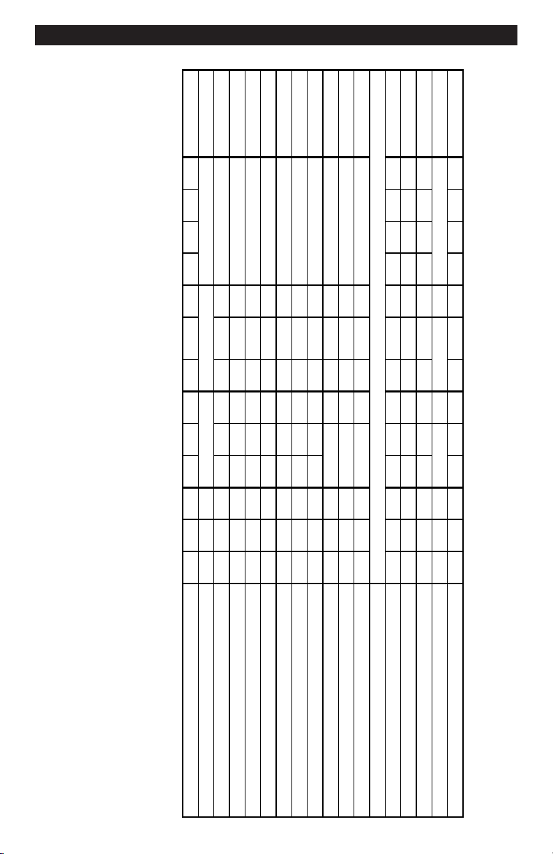
SC-7500A CONTROL PANEL GUIDE
MODE OF OPERATION
C
h
a
r
g
e
d
C
h
a
r
g
i
n
g
C
h
e
c
k
B
a
t
t
e
r
y
%
V
o
l
t
a
g
e
A
l
t
e
r
n
a
t
o
r
%
2
A
1
2
A
Ż
Ź
3
0
A
7
5
A
S
t
a
r
t
1
2
V
R
e
g
u
l
a
r
1
2
V
D
e
e
p
-
C
y
c
l
e
1
2
V
A
G
M
,
G
e
l
6
V
R
e
g
u
l
a
r
Digital
Display
Initial power-up, battery not detected O O O 0.0
No battery or reversed battery detected O 0% or 0.0V
Battery tester activated O 0~100%
Battery tester with charged battery O O 100%
Battery tester with no battery O O 0%
Voltage meter activated O 0.0~17.0V
Alternator tester activated O 0~199%
Alternator tester on good alternator O O 0~199%
Alternator tester on bad alternator O O 0~199%
2 Amp charge with battery detected O O xx% or xx.xV
12 Ż Ź 30 Amp charge activated O O xx% or xx.xV
Charge complete - Maintain Mode started O 100% or xx.xV
80A Engine Start
Waiting for engine crank O O O 1.0~16.0V
Cranking engine O O 5ĺ0
Cool down after cranking B 180ĺ0
Desulfation mode activated B 15% or 16V
Charge aborted B 8.8.8. (B)
User selected
User selected
User selected
User selectedUser selected
User sel.
User sel.
User sel.
O indicates an LED that is on continuously.
User sel. User selected
B indicates an LED that blinks on and off.
User selected
User selected
User selected
User selected
User selected
User selected
User selected
User selected
User selected
10
Page 11

USING THE BUILT-IN BATTERY TESTER
OVERVIEW
This battery charger has a built-in battery
tester that displays either an accurate
battery voltage or an estimate of the
battery’s relative charge based on the
battery voltage and the Battery Council
International scale.
TESTING SEQUENCE
There are four basic steps required to
use the SC-7500A as a battery tester.
1. Connect the charger battery clamps to
the battery. Be sure to follow all of the
precautions listed under “OPERATING
INSTRUCTIONS”.
2. Connect the charger power cord to a 120V
AC 2-prong wall outlet. Again, be sure to
follow all of the precautions listed under
“OPERATING INSTRUCTIONS”.
3. If necessary, press the BATTERY
TYPE button until the correct type is
indicated.
4. Read the voltage on the digital display
or press the display mode button to set
the tester to BATTERY % and read the
battery percent.
TESTER AND CHARGER
When rst turned on, the SC-7500A operates only as a tester, not as a charger. To
continue to use it as only a tester, avoid
pressing the CHARGE RATE switch button. Selecting a charge rate activates the
battery charger and deactivates the tester.
Pressing the CHARGE RATE button when
the 75A Start LED is lit (except during the
180 second cool down) will shut off the
charger and activate the tester.
POWER-UP IDLE TIME LIMIT
If no switch button is pressed within ten
minutes after the battery is rst powered
up, the charger will automatically switch
from tester to charger, if a battery is
connected. In that case, the battery will
be set for the 2A charge rate and 12V
REGULAR battery type.
TESTER WITHOUT TIME LIMIT
If either the DISPLAY MODE or BATTERY TYPE button is pressed within
the rst ten minutes after the battery is
powered up, the battery will remain a
tester (not a charger) indenitely, unless
a charge rate is selected.
TESTING AFTER CHARGING
After the battery has been changed from
tester to charger (by selecting a charge
rate), it remains a charger. To change
the battery back to a tester, press the
CHARGE RATE switch until all charge
rate LEDs are off.
TESTER STATUS LEDs
When the SC-7500A is operating as
a battery tester, the status LEDs light
under the following conditions:
• The CHARGED (green) LED will light if
a charged battery is tested.
• The CHARGING (yellow) LED does not
light in the battery test mode.
• The CHECK (red) LED lights unless a
properly connected battery is detected.
• When the tester display mode is set to
VOLTAGE, the CHARGED and CHARGING LEDs won't light.
INITIAL PERCENT CALCULATION
When a battery % is calculated for the
rst time after connecting a battery, the
digital display will show three dashes
(“---”) for a period as long as several
seconds while the tester analyzes the
battery.
NOTES FOR TESTING BATTERY %
A recently charged battery could have a
temporarily high voltage due to what is
known as “surface charge”. The voltage
of such a battery will gradually drop during
the period immediately after the charging
system is disengaged. Consequently, the
tester could display inconsistent values
for such a battery. For a more accurate
reading, the surface charge should be
removed by temporarily creating a load on
the battery, such as by turning on lights or
other accessories.
The battery % ranges from 0 to 100.
The battery tester is only designed to test
batteries. Testing a device with a rapidly
changing voltage could yield unexpected
or inaccurate results.
11
Page 12

USING THE BUILT-IN ALTERNATOR TESTER
This battery charger has a built-in alternator tester that displays either an accurate alternator voltage or an estimate of
the alternator’s relative output compared
to normal alternators. The Alternator %
values displayed should be taken as
general reference, not precise diagnosis.
The alternator tester functions the same
as the battery tester (see previous section of this manual for details) with a few
differences.
TESTING SEQUENCE
There are three basic steps required to use
the SC-7500A as an alternator tester.
1. Connect the charger battery clamps to
the battery or charging system. Be sure
to follow all of the precautions listed
under “OPERATING INSTRUCTIONS”.
2. Connect the charger power cord to a
120V AC 2-prong wall outlet. Again, be
sure to follow all of the precautions listed
under “OPERATING INSTRUCTIONS”.
3. Start the vehicle and turn on the
vehicle’s headlights. Read the voltage
on the digital display or press the
DISPLAY MODE button to set the
tester to ALTERNATOR % and read
the alternator percent.
TESTER STATUS LEDs
When the SC-7500A is operating as an
alternator tester, the status LEDs light
under the following conditions.
• The CHARGED (green) LED will light
if the output of the charging system is
at the normally desired level.
• The CHARGING (yellow) LED does
not light in the alternator test mode.
• The CHECK (red) LED lights if the
VOLTAGE is much higher or lower
than normally desired.
• When the tester display mode is set
to VOLTAGE, the CHARGED and
CHARGING LEDs won't light (it could
be testing a battery or an alternator).
ALTERNATOR TESTING NOTES
• The alternator percent display can
range from 0 to 199.
• The DISPLAY MODE cannot be set to
ALTERNATOR % during charging.
12
Page 13

BATTERY PERCENT AND CHARGE TIME
This charger adjusts the charging time in
order to charge the battery completely,
efciently and safely. The microprocessor automatically makes the necessary
decisions. However, this section includes
guidelines that can be used to estimate
charging times.
The duration of the charging process depends on three factors:
1. Battery State – If a battery has only
been slightly discharged, it can be
charged in less than a few hours.
The same battery could take up to 10
hours if very weak. The battery state
can be estimated by using the built-in
tester (see page 11). The lower the
reading the longer charging will take.
2. Battery rating – A higher rated
battery will take longer to charge
than a lower rated battery under the
same conditions. A battery is rated in
ampere-hours (AH), reserve capacity
(RC) and cold cranking amps (CCA).
The lower the rating the quicker the
battery will be charged.
3. Charge rate – The charge rate is
measured in amps. This charger
provides charge rates of 2A, 12A
and 30A. The 75A rate is for engine
start only. The 2A rate is for charging smaller batteries such as those
used for motorcycles and garden
tractors. Such batteries should not be
charged using the 12A or 30A rate.
The 12A and 30A rates are for charging larger batteries. In the 30A mode,
the charger begins at a low charge
rate and increases the charge rate if
it is determined that the battery can
accept the higher rate. All charging
modes will decrease the charge rate
as the battery approaches maximum
charge. After the charging process
has started, the digital display can be
used to determine charging progress
by selecting the BATTERY % mode.
There are some important facts to keep in
mind when charging a battery.
• When the display indicates 77%
charged, the battery has been charged
enough to start most vehicles and has
already been charged as much as by
many other battery chargers.
• When the display indicates 85%
charged, the battery has already been
charged at least as much as by most
other battery chargers.
• The battery % shown in tester mode
is an estimate based on the battery voltage and the Battery Council
International scale. The battery %
shown in charger mode is an estimate
of the relative charge in the battery
compared to the charge it should have
if the charging process is allowed to
complete.
• The battery % shown in tester mode
can be used to estimate the relative
charge time. The lower the % shown,
the longer the charge time for a given
battery.
• The battery % shown in charger mode
is an indication of the relative progress
of the charging process. The higher
the battery % displayed, the less
charge time remains.
• The more a battery is discharged,
the faster it absorbs charge from a
charger. That means that the battery
% increases faster at the beginning
of the charging process than at the
end. In other words, it takes longer
for the battery to absorb the last few
percent of charge than the rst several
percent.
13
Page 14

CHARGING TIPS
Read this entire manual before using your charger. The tips below serve only as a guide
for specic situations.
If your vehicle won’t start: You don’t need
to fully charge a battery to start your vehicle. If the charger won’t start your vehicle
using the 75A START rate, try charging the
battery using the 12A 30A rate for 10
or 15 minutes. That should charge the battery enough to allow the 75A START rate
to start the vehicle. If the vehicle will then
be operated continuously for an extended
period (such as a long drive), the vehicle
could charge the battery back to normal
during that period. If the vehicle will only
be operated for a short period (short drive),
the battery might need to be charged again
before it could start the vehicle again.
Reviving your battery: If you only wish
to charge your battery enough to operate
your vehicle, you don’t need to wait for the
entire charging process to be completed.
When the charger displays a battery %
of 77 or more (see page 13), the battery
has usually been charged enough for the
vehicle to start and operate normally.
Completing an interrupted charge: If
the charging process has been interrupted
and restarted after the charger displays a
battery % of 85 or more, the charger could
go straight to Maintain Mode (see page 8).
However, if the original charge was started
using 12A 30A, the charge can often
be completed using the 2A rate.
MAINTENANCE AND CARE
A minimal amount of care can keep your battery charger working properly for years.
1. Clean the clamps each time you are nished charging. Wipe off any battery uid
that may have come in contact with the clamps to prevent corrosion.
2. Coil the input and output cords neatly when storing the charger. This will help prevent accidental damage to the cords and charger.
3. Occasional cleaning of the case of the charger with a soft cloth will keep the nish
shiny.
14
Page 15

TROUBLESHOOTING
Performance problems often can be corrected by the user. Please read through this chart
for a possible solution to common problems.
PROBLEM POSSIBLE CAUSE SOLUTION
The battery is connected
and the charger is on,
but isn't charging.
Indicator lights are lit in
an erratic manner not
explained in the “Using
Your Battery Charger”
section.
The charger is in tester
mode, not charger mode.
You might have accidentally activated a special
diagnostic mode.
Press the CHARGE
RATE button to activate
charging and select a
charge rate.
Make sure nothing is
touching the control
panel, then unplug the
charger and plug it in
again.
The CHECK (red) LED
always ashes before
the battery is completely
charged.
Engine crank time is less
than specied.
The green CHARGED
LED lights a few minutes
after connecting to the
battery.
The charger may be
defective.
The incorrect BATTERY
TYPE may have been
selected.
This will happen if the
battery did not reach full
charge within 24 hours.
May be due to a very
large battery or a bank
of batteries requiring
more power than a 30/12
Amp charger can deliver
within 24 hours. The battery may also be faulty.
Starter motor may be
drawing more than 80
Amps.
The battery may be
fully charged or recently
charged, leaving the battery voltage high enough
to appear to be fully
charged.
Return to place of purchase for replacement.
Reset the charger by
unplugging it or briey
disconnecting it or briey
disconnecting the negative battery clip. Select
the desired CHARGE
RATE and BATTERY
TYPE again, if necessary.
Charge the battery at the
12A 30A rate for 10
to 15 minutes then crank
the engine.
If the battery is in a vehicle, turn the headlights
on for a few minutes
to reduce the battery
voltage and try charging
again.
The incorrect BATTERY
TYPE may have been
selected.
15
Reset the charger by unplugging it or briey disconnecting the negative
battery clip. Select the
desired CHARGE RATE
and BATTERY TYPE
again, if necessary.
Page 16

WARRANTY
SCHUMACHER ELECTRIC CORPORATION,
801 BUSINESS CENTER DRIVE,
MOUNT PROSPECT, ILLINOIS 60056-2179
MAKES THIS LIMITED WARRANTY TO THE ORIGINAL PURCHASER AT RETAIL OF
THIS PRODUCT. THIS LIMITED WARRANTY IS NOT TRANSFERABLE.
Schumacher Electric Corporation warrants this battery charger for one year from date of
purchase at retail against defective material or workmanship. If such should occur, the
unit will be repaired or replaced at the option of the manufacturer. It is the obligation of
the purchaser to forward the unit together with proof of purchase, transportation and/or
mailing charges prepaid to the manufacturer or its authorized representative.
This limited warranty is void if the product is misused, subjected to careless handling, or
repaired by anyone other than the manufacturer or its authorized representative.
The manufacturer makes no warranty other than this limited warranty and expressly
excludes any implied warranty including any warranty for consequential damages.
THIS IS THE ONLY EXPRESS LIMITED WARRANTY AND THE MANUFACTURER NEITHER ASSUMES NOR AUTHORIZES ANYONE TO ASSUME OR MAKE ANY OTHER
OBLIGATION TOWARDS THE PRODUCT OTHER THAN THIS EXPRESS LIMITED
WARRANTY. THE MANUFACTURER MAKES NO WARRANTY OF MERCHANTABILITY OR FITNESS FOR PURPOSE OF THIS PRODUCT AND EXPRESSLY EXCLUDES
SUCH FROM THIS LIMITED WARRANTY.
SOME STATES DO NOT ALLOW THE EXCLUSION OR LIMITATION OF INCIDENTAL
OR CONSEQUENTIAL DAMAGES OR LENGTH OF IMPLIED WARRANTY SO THE
ABOVE LIMITATIONS OR EXCLUSIONS MAY NOT APPLY TO YOU.
THIS WARRANTY GIVES YOU SPECIFIC LEGAL RIGHTS AND YOU MAY ALSO HAVE
OTHER RIGHTS THAT VARY FROM STATE TO STATE.
WARRANTY VALIDATION: The enclosed “Warranty Validation Card” must be completed
and mailed within 10 days of product purchase to activate this limited warranty.
16
 Loading...