


Schumacher PC-2000,PC-3000 Owner's Manual
PC-2000
0099001585-00
OWNERS MANUAL
MANUAL DEL USUARIO
GUIDE D’UTILISATION
PLEASE SAVE THIS OWNERS MANUAL AND READ BEFORE EACH USE.
This manual will explain how to use the converter safely and effectively. Please
read and follow these instructions and precautions carefully.
POR FAVOR CONSERVE ESTE MANUAL DEL USUARIO Y LEALO ANTES
DE CADA USO. En este manual le explica cómo utilizar el convertidor de manera
segura y conable. Por favor, lea y siga las siguientes instrucciones y precauciones.
ESSAYER DE GARDER LE MANUEL D’INSTRUCTIONS ET LE LIRE AVANT
CHAQUE UTILISATION. Ce manuel explique comment utiliser l’unité d’une façon
sûre et efcace. S’il vous plaît lisez et suivez ces instructions et précautions.
PC-3000
Models / Modelos / Modèles :
PC-2000, PC-3000
Power Converter
Converts 12V DC Battery Power to AC Household Power
Convertidor de Energía
Convierte la energía 12V CD de baterías a 120V CA de energía doméstica
Convertisseur de puissance
Convertit la tension d’une batterie 12V CC en 120V CA domestique

CONTENTS
IMPORTANT SAFETY INSTRUCTIONS ...............................................................................4
PERSONAL PRECAUTIONS .................................................................................................4
CONVERTER LOCATION ...................................................................................................... 5
FEATURES ............................................................................................................................. 5
BEFORE USING YOUR CONVERTER ..................................................................................5
FASTENING THE CONVERTER TO A FLAT SURFACE .......................................................6
CONNECTING CONVERTER CABLES ................................................................................. 6
BATTERY BANK INSTRUCTIONS ......................................................................................... 7
OPERATING INSTRUCTIONS ............................................................................................... 8
POWER SOURCE .................................................................................................................. 9
LED INDICATOR AND SHUTDOWN PROTECTION .............................................................9
IF THE CONVERTER’S FUSE BLOWS .................................................................................9
MAINTENANCE AND STORAGE INSTRUCTIONS ...............................................................9
TROUBLESHOOTING .........................................................................................................10
SPECIFICATIONS ................................................................................................................ 10
REPLACEMENT PARTS ...................................................................................................... 11
BEFORE RETURNING FOR REPAIRS ............................................................................... 11
LIMITED WARRANTY ..........................................................................................................12
WARRANTY CARD ..............................................................................................................31
CONTENIDOS
INSTRUCCIONES IMPORTANTES DE SEGURIDAD ......................................................... 13
PRECAUCIONES PERSONALES .......................................................................................14
UBICACIÓN DEL CONVERTIDOR ......................................................................................14
CARACTERÍSTICAS ............................................................................................................ 14
ANTES DE USAR SU CONVERTIDOR ...............................................................................14
PARA SUJETAR EL CONVERTIDOR A UNA SUPERFICIE PLANA ....................................15
PARA CONECTAR LOS CABLES DEL CONVERTIDOR .....................................................15
INSTRUCCIONES PARA UN BANCO DE BATERÍAS ........................................................ 16
INSTRUCCIONES DE OPERACIÓN ...................................................................................17
FUENTE DE ENERGÍA ........................................................................................................18
INDICADOR LED Y PROTECCIÓN DE DE APAGADO ....................................................... 18
SI SE QUEMA EL FUSIBLE DEL CONVERTIDOR ..............................................................19
INSTRUCCIONES DE MANTENIMIENTO Y ALMACENAMIENTO ..................................... 19
LOCALIZACIÓN Y SOLUCIÓN DE PROBLEMAS ...............................................................19
ESPECIFICACIONES ..........................................................................................................20
PIEZAS DE REPUESTO ......................................................................................................20
ANTES DE DEVOLVER A REPARACIONES ....................................................................... 21
GARANTÍA LIMITADA ..........................................................................................................21
TARJETA DE GARANTÍA .....................................................................................................31

TABLE DES MATIÈRES
CONSIGNES DE SÉCURITÉ IMPORTANTES ....................................................................22
MESURES DE SÉCURITÉ PERSONNELLE ....................................................................... 23
EMPLACEMENT DU CONVERTISSEUR ............................................................................23
CARACTÉRISTIQUES ......................................................................................................... 23
AVANT D’UTILISER VOTRE CONVERTISSEUR ................................................................23
FIXATION DE LE CONVERTISSEUR SUR UNE SURFACE PLANE ..................................24
RACCORDER DES CÀBLES DU CONVERTISSEUR ......................................................... 24
INSTRUCTIONS BANQUE BATTERIE ................................................................................ 25
MODE D’EMPLOI ................................................................................................................. 26
SOURCE D’ALIMENTATION ................................................................................................27
INDICATEUR DEL ET PROTECTION D’ARRÊT .................................................................27
SI LE FUSIBLE DU CONVERTISSEUR SAUTE .................................................................. 28
ENTRETIEN ET STOCKAGE INSTRUCTIONS ...................................................................28
DÉPANNAGE .......................................................................................................................28
SPÉCIFICATIONS ................................................................................................................ 29
PIÊCES DE RECHANGE ..................................................................................................... 29
AVANT DE L’ENVOYER POUR RÉPARATIONS .................................................................30
GARANTIE LIMITÉE ............................................................................................................30
CARTE DE GARANTIE ........................................................................................................32

• 4 •
1. IMPORTANT SAFETY INSTRUCTIONS
SAVE THESE INSTRUCTIONS.
1.1 SAVE THESE INSTRUCTIONS.
This manual contains important safety
and operating instructions for converter
models PC-2000 and PC-3000. This
manual will show you how to use your
converter safely and effectively. Please
read, understand and follow these
instructions and precautions carefully.
WARNING: RISK OF ELECTRIC
SHOCK OR FIRE.
1.2 WARNING: Pursuant to California
Proposition 65, this product contains
chemicals known to the state of California
to cause cancer and birth defects or other
reproductive harm. Wash hands after
handling.
1.3 WARNING: People with pacemakers
should consult their physician before
using the converter. Electromagnetic
elds in close proximity to a heart
pacemaker may cause pacemaker
interference or pacemaker failure.
1.4 IMPORTANT: Do not use in a marine
application.
1.5 Keep out of reach of children.
1.6 Do not expose converter to rain or snow.
1.7 Use of an attachment not recommended
or sold by the unit manufacturer may
result in a risk of re, electric shock, or
injury to persons.
1.8 Do not disassemble the unit; take it to
a qualied serviceman when service or
repair is required. Incorrect reassembly
may result in a risk of electric shock or re.
1.9 To reduce risk of electric shock, unplug
unit from outlet before attempting any
maintenance or cleaning. Turning off
controls will not reduce this risk.
1.10 For the most effective use, place the
power converter on a at surface.
1.11 Keep the converter well ventilated, in
order to properly disperse heat generated
while it is use. Make sure there are
several inches of clearance around the
top and sides and do not block the slots
of the converter.
1.12 Do not place the converter in areas
such as battery compartments or engine
compartments, where fumes or gases
may accumulate.
1.13 DO NOT operate the converter if you, the
converter, the device being operated or any
other surfaces that may come into contact
with any power source are wet. Water and
many other liquids can conduct electricity,
which may lead to serious injury or death.
1.14 Do not place the converter on or near
heating vents, radiators or other sources
of heat or ammable materials.
1.15 Do not place the converter in direct
sunlight. The ideal air temperature for
operation is between 50° and 80°F.
1.16 Only connect the power converter to a 12V
battery or power supply. Do not attempt to
connect the converter to any other power
source, including an AC power source.
Connecting to a 6V or 16V battery will
cause damage to the converter.
1.17 Do not use with positive ground electrical
systems.
1.18 Make sure the AC plug is tight.
1.19 Do not modify the AC receptacle in
any way.
1.20 Do not try extending or otherwise
changing the 12V power cord supplied
with your converter. Make sure the cord
connections are tight.
1.21 Incorrect operation of your converter may
result in damage and personal injury.
WARNING: The converter output is 120V
AC and can shock or electrocute the same
as any ordinary household AC wall outlet.
1.22 Do not use the converter with a product
that draws a higher wattage than the
converter can provide, as this may cause
damage to the converter and product.
1.23 This device does not include an internal
Ground Fault Circuit Interrupter (GFCI).
For GFCI protection, use a Coleman
Cable 02822 GFCI outlet, or its
equivalent.
2. PERSONAL PRECAUTIONS
2.1 Wear complete eye protection and
protective clothing when working
near lead-acid batteries. Always have
someone nearby for help.
2.2 Remove all personal metal items from
your body, such as rings, bracelets,
necklaces and watches. A lead-acid
battery can produce a short circuit current
high enough to weld a ring to metal,
causing a severe burn.
2.3 Never smoke or allow a spark or ame in
the vicinity of the battery or engine.

• 5 •
3. CONVERTER LOCATION
3.1 Never place unit directly above battery;
gases from battery will corrode and
damage the converter.
3.2 Never allow battery acid to drip on unit
when reading gravity or lling battery.
3.3 Do not operate converter in a closed-in
area or restrict ventilation in any way.
4. FEATURES
• ON/OFF rocker switch
• LED indicator
Green indicates Power ON
Red indicates Overload/Interruption
in power
• 12 Volt power cord
• 120V standard AC outlets
Model PC-2000 includes 3 outlets
Model PC-3000 features 4 outlets
• USB port(s) – 5V, 2.0A
Model PC-2000 includes one port
Model PC-3000 features 2 ports
• High-speed cooling fans (2)
To keep the converter cool, the fans
speeds up as the load increases. The fans
do not run when the converter is turned off.
• Positive Battery Cable Terminal (Red)
• Negative Battery Cable Terminal
(Black)
• Ground Terminal and ground wire
Grounds converter, to protect against
electrical shock.
• Thermal Protection
When the thermal resistor exceeds
80° C (176° F), the converter shuts
down until it cools off, and then
automatically restarts.
•Surge Protection
When the power input from the vehicle’s
battery exceeds 15.5 volts, the converter
shuts down.
•Low-Battery Protection
When the power input from the vehicle’s
battery drops to below 10 volts, the red
LED will light, and the converter will shut
down.
5. BEFORE USING YOUR CONVERTER
Do not use the converter with a product
that draws a higher wattage than the
converter can provide, as this may cause
damage to the converter and product.
When you turn on a device or a tool that
runs on a motor, the device goes through
two stages:
1. Start Up – Requiring an initial surge
of power (commonly known as the
“starting” or “peak” load).
2. Continuous Operation – Power
consumption drops (commonly known
as the “continuous load”).
The wattage (WATTS) or amperes (AMPS)
can normally be found stamped or printed
on most devices and equipment, or in
the user’s manual. Otherwise, contact
the manufacturer to nd out whether the
device you want to use is compatible with
a modied sine wave.
To calculate the wattage:
Wattage = AMPS x 120 (AC Voltage).
To calculate the starting load:
Starting Load = 2 x wattage.
In general, the startup load of the device
or power tool determines whether your
converter has the capability to power it.
To calculate the continuous load:
Continuous Load = AMPS x 120
(AC Voltage).
IMPORTANT: Always run a test to
establish whether the converter will
operate a particular piece of equipment or
device. In the event of a power overload,
the converter is designed to automatically
shut down.
This safety feature prevents damaging
the converter while testing devices and
equipment within the wattage range of the
converter.
WARNING: Do not use this converter
to power sensitive devices, such as
medical devices.
If a device does not operate properly
when rst connected to the converter, turn
the converter ON/OFF switch ON, OFF,
and ON again in quick succession. If this
procedure is not successful, it is likely that
the converter does not have the required
capacity to operate the device in question.

• 6 •
IMPORTANT: This converter uses a
modied sine waveform (diagram A)
which is not quite the same as power
company electricity (diagram B). For the
following devices, we strongly recommend
that you use caution and check the
device’s manual to make sure it is
compatible with modied sine waveform.
1. Switch mode power supplies
2. Linear power supplies
3. Class 2 transformers
4. Line lter capacitors
5. Shaded pole motors
6. Fan motors
7. Microwave ovens
8. Fluorescent and high intensity lamps
(with a ballast)
9. Transformerless battery chargers
Using the converter with any of these
devices may cause the device to run
warmer or overheat.
Modiedsinewaveform
produced by converter
Diagram A
Diagram B
Pure sine waveform
typical of home AC outlet
IMPORTANT: If you are using the
power converter to operate a battery
charger, monitor the temperature of the
battery charger for about 10 minutes.
If the battery charger becomes
abnormally warm, disconnect it from
the converter immediately.
6. FASTENING THE CONVERTER TO A FLAT SURFACE
For your convenience, the converter may
be fastened horizontally to a at surface.
The area where the converter is to be
fastened must be dry, well-ventilated
and away from any combustible material
or fumes.
1. Turn off and disconnect the converter.
2. Place the back of the converter with
the mounting bracket against a at,
secure surface.
3. Attach the converter, using corrosion-
resistant screws.
7. CONNECTING CONVERTER CABLES
The converter and power source must be
in the OFF mode.
IMPORTANT: Make sure to connect your
converter only to a 12 volt power supply.
To avoid electrical shock, it is necessary
to ground the converter as well as the
device powering it. The converter should
be grounded, using a 16 AWG copper
wire (included).
NOTE: Do not turn on the converter or the
power source until the converter and the
power source are grounded.
TO GROUND THE CONVERTER
1. Turn off and disconnect the converter.
2. Locate the chassis ground screw on
the back of the converter.
3. Remove the outer hex nut and loosen
the second hex nut.
4. Attach the grounding wire’s ring
connector to the ground terminal of
the converter.
5. Tighten the hex nut securely. Then
replace the other hex nut and tighten
it securely.
6. Attach the other end of the wire to a
properly grounded location:
Vehicle: Connect to the chassis, unpainted
frame part, or engine block of the vehicle.
Fixed location: Connect to a ground rod
or other appropriately rated ground.
CONNECTING CONVERTER CABLES
TO THE CONVERTER
1. Locate the Positive and Negative
terminals on the left side of the
converter.
2. From the POSITIVE (RED) and the
NEGATIVE (BLACK) terminals, remove
the hex nut, split lock and at washer.
3. Place the POSITIVE (RED) ring
connectors onto the POSITIVE
(RED) converter terminal. Place the
NEGATIVE (BLACK) ring connectors

• 7 •
onto the NEGATIVE (BLACK)
converter terminal.
4. Place a at washer and split lock on
top of the ring connectors. Put a hex
nut over these and tighten.
Hex nut
Flat
washer
Split
lock
Ring
connectors
and cables
Converter
terminal
CONNECTING THE CONVERTER
CABLE TO A 12V BATTERY OR
12V POWER SOURCE:
1. Keep hands, hair, clothing and jewelry
clear of battery terminals.
2. Wear eye protection and protective
clothing.
3. For a negative-grounded vehicle
(do not use with positive ground
electrical systems), connect the
POSITIVE (RED) ring terminal from
the converter to the POSITIVE (POS,
P, +) ungrounded post of the battery.
Connect the NEGATIVE (BLACK)
ring terminal to the vehicle chassis or
engine block away from the battery.
Do not connect the terminal to the
carburetor, fuel lines or sheet-metal
body parts. Connect to a heavy
gauge metal part of the frame or
engine block.
4. To disconnect the converter, remove
rst the negative terminal and then the
positive terminal.
IMPORTANT: Failure to make the correct
connections will result in blown fuses and
permanent damage to the converter.
8. BATTERY BANK INSTRUCTIONS
BATTERY BANK ASSEMBLY
WARNING: Read these safety
instructions before assembling the
battery bank.
•Connect batteries ONLY in parallel
(negative terminals together to one
cable; positive terminals together
to the other cable), as shown in the
Battery Bank Example.
•Do not connect 12V batteries in a
series with the negative of one battery
connected to the positive of the next.
DANGER: CONNECTING INCORRECTLY
MAY RESULT IN VOLTAGE HIGH
ENOUGH TO CAUSE ELECTROCUTION.
• While assembling the battery bank, wear
splash-resistant ANSI-approved safety
goggles and electrically insulated gloves.
• Connect ONLY similar batteries together
in a battery bank. Do not connect old
to new, ooded to gel cells, or batteries
with different capacities.
• Use extension cables with the specied
gauge (or thicker).
PC-2000
6' or less: 6 AWG (2 sets)
6-10': 4 AWG (2 sets)
PC-3000
6' or less: 4 AWG (2 sets)
6-10': 2 AWG (2 sets)
WARNING:
RISK OF EXPLOSIVE GASES.
• Assemble the battery bank in a clean,
well-ventilated location, away from
ignition sources and ammable materials.
• To reduce risk of battery explosion,
follow these instructions and those
published by the battery manufacturer
and manufacturer of any equipment
you intend to use in vicinity of a battery.
Review cautionary markings on these
products.
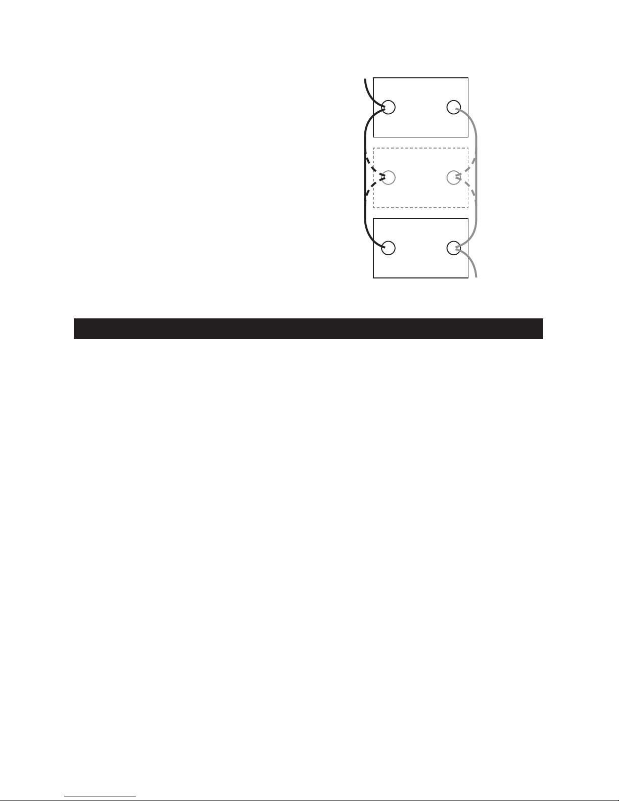
CONNECTING THE BATTERIES
IN PARALLEL
1. First, connect all of the positive
terminals to each other.
2. Next, connect all of the negative
terminals to each other.
3. Connect the negative and positive
output cables to opposite ends of
the bank. Do not allow the output
cables to touch one another.
4. Test the voltages at the output cables,
to make sure that the battery bank is
correctly wired.
5. If the voltage is higher than 13 volts,
part of the battery bank is probably
connected in series (a negative
terminal of one battery attached to
a positive terminal of another) instead
of in parallel.
• 8 •
6. Carefully examine the diagram and
correct the wiring before attaching to
the converter.
7. Make sure the converter’s switch is
set to OFF (O).
8. Connect the output cables from the
battery bank to the converter.
†
Bank Capacity = (single battery
capacity) x (# of batteries)
400 Ah capacity is for (2) 200 Ah
batteries.
*200 Ah batteries shown for illustration
purposes.
12V
lead-acid
battery
200 Ah*
Connect additional
12V 200 Ah*
lead-acid
batteries here
to increase capacity
12V
lead-acid
battery
200 Ah*
-
+
+
-
+
-
Example:
12V/400 Ah† BATTERY BANK
OUTPUT
to NEGATIVE
converter
terminal
OUTPUT
to POSITIVE
converter
terminal
9. OPERATING INSTRUCTIONS
1. Connect the converter (see Connecting
Converter Cables section.
2. Switch the converter’s ON/OFF switch
to the ON (I) position.
3. The GREEN LED indicator will light,
indicating the converter is receiving
power.
4. Switch the converter’s ON/OFF
switch to the OFF (O) position. (The
GREEN LED may ash briey and/or
the internal speaker may make a brief
“beep”. This is normal.)
5. Make sure the device to be operated
is turned OFF.
6. Plug the device into the converter’s
AC outlet.
7. Switch the converter’s ON/OFF switch
to the ON (I) position.
8. Turn the device on.
9. To disconnect, reverse the above
procedure.
NOTE: If more than one device is to be
powered, start one device at a time, to
avoid a power surge and overloading
the converter. The surge load of each
device should not exceed the converter’s
Continuous Operation wattage rate.
IMPORTANT: Using the converter
with some rechargeable devices may
damage the converter and/or device. If
you are using the converter to operate
a rechargeable device, monitor the
temperature of the converter for about
10 minutes. If the converter becomes
abnormally hot, disconnect it from the
device immediately; do not use the device
with the converter.
USING THE CONVERTER TO OPERATE
A TV OR AUDIO DEVICE
The converter is shielded and ltered to
minimize signal interference. Despite this,
some interference may occur with your
television picture, especially with weak
signals. Below are some suggestions to
improve reception.
1. Try altering the position of the converter,
antenna cables, and television power
cord. Add an extension cord from the
converter to the TV, to isolate its power
cord and antenna cables from the 12
volt power source.
2. Try coiling the television power cord
and the input cables running from the
12 volt power source to the converter.
3. Afx one or several “Ferrite Data
Line Filters” to the television power
cord. Ferrite Data Line Filters can be
purchased at most electronic supply
stores.
4. Try grounding the converter with a 16
AWG (minimum) wire, using as short
of an extension length as possible.
NOTE: You may hear a “buzzing”
sound being emitted from inexpensive
sound systems when operated with the
converter. This is due to ineffective lters
in the sound system’s power supply.

• 9 •
Unfortunately, this problem can only be
resolved by purchasing a sound system
with a higher quality power supply or
higher quality lter.
USING THE USB PORT(S)
The USB port provides up to 2A at 5V DC.
Model PC-2000 includes one port.
Model PC-3000 includes two ports.
1. Plug the device into the USB port.
2. Turn the USB device on.
3. Reverse these steps when nished
using the USB port.
WARNING: The converter draws power,
even when the switch is OFF. To avoid
battery drain, disconnect the converter
when not in use.
10. POWER SOURCE
Your average automobile battery at full
charge will provide an ample power supply
to the converter when the engine is on.
Keep the car running at all times when
using the converter. The actual length of
time the converter will function depends on
the age and condition of the battery and the
power demand being placed by the device
being operated with the converter.
When possible, recharge your batteries
when they are not more than 50%
discharged. This gives the batteries a
much longer life cycle than recharging
when they are more deeply discharged.
The power converter has a battery low
voltage shutdown at 10V±0.5V DC. With
moderate to heavy loads, this will protect
against over-discharging the battery. If the
converter is running only light loads it is
advisable to recharge before the converter
low voltage shutdown point is reached.
IMPORTANT: The converter draws low
amperage from the battery with the main
ON/OFF switch turned on and no load
connected. To prevent battery discharge,
turn the converter off when you are not
using it.
11. LED INDICATOR AND SHUTDOWN PROTECTION
The Green LED lights automatically
when then converter is plugged into a 12
volt DC power source and is turned on.
The Red LED lights and the converter
automatically turns itself off under the
following conditions:
1. When the power input from the
vehicle’s battery drops to approximately
10.5 volts, the Red LED lights. When
the voltage goes down below 10 VDC,
the converter shuts off. Recharge or
replace the battery.
2. When the power input from the vehicle’s
battery exceeds 15.5 volts, high voltage
overload protection occurs.
3. The continuous load demand from the
equipment or device being operated
exceeds the continuous load rating of
the converter. Use a higher capacity
converter or lower rated device.
4. The thermal resistor exceeds
80° C (176° F.) Allow the converter to
cool. Do not block the cooling slots or
air ow over and through the converter.
Reduce the load on the converter to
the continuous rated output.
RESET: To reset after shutdown occurs,
switch the converter’s ON/OFF switch to the
OFF (O) position. Check the source of the
problem and correct. Switch the converter’s
ON/OFF switch to the ON (I) position.
12. IF THE CONVERTER’S FUSE BLOWS
Your power converter is tted with fuses,
which should not have to be replaced
under normal operating conditions. A
blown fuse is usually caused by reverse
polarity or a short circuit within the device
or equipment being operated.
If a fuse does blow, take the converter to
a qualied technician for repair.
13. MAINTENANCE AND STORAGE INSTRUCTIONS
13.1 Before each use, ensure that all of the
converter’s components are in place and
in good working condition.
13.2 After use and before performing
maintenance, unplug and disconnect
the converter.
13.3 Use a clean, dry cloth to wipe external
surfaces of the converter’s case.
13.4 Servicing does not require opening the
unit, as there are no user-serviceable
parts. All servicing should be performed
by qualied service personnel.
13.5 Store inside, in a cool, dry place, out of
the reach of children.
13.6 Recycle or properly dispose of internal
electrical components.

• 10 •
14. TROUBLESHOOTING
PROBLEM POSSIBLE CAUSE REASON/SOLUTION
Low or no output
voltage.
Poor contact at terminals.
Using incorrect type of voltmeter
to test output voltage.
Disconnect and reconnect the 12V
connections.
Use a true RMS reading meter.
Red LED is lit. The battery voltage is below
10.5 volts.
The equipment being operated is
drawing too much power.
The converter is too hot (thermal
shutdown).
Recharge or replace the battery.
Use a higher capacity converter; do
not use with this equipment.
Allow converter to cool. Check for
adequate ventilation. Reduce the
load on the converter to the rated
continuous power output.
Device does not
operate properly
when rst connected
to the converter.
The converter may not have
the required capacity to operate
the device.
Turn the converter switch OFF and
ON, to reset the converter.
15. SPECIFICATIONS
PC-2000
Continuous output power ........................................................................................2000 W
Surge output power (0.1 second) ...........................................................................4000 W
Nominal input voltage ................................................................................. 12.8-13.2 VDC
Nominal output voltage .................................................................................... 120±5 VAC
Operating input voltage range .................................................................... 10.0-15.0 VDC
Output frequency .............................................................................................60 Hz±2 Hz
Maximum no load current draw (at nominal input voltage) ....................................1.0 ADC
Full load input current ...........................................................................................180 ADC
Maximum efciency .....................................................................................................90%
Input overvoltage shutdown (at no load) ....................................................... 15.5±0.5VDC
Input undervoltage shutdown (at no load) .................................................... 10.0±0.5VDC
Input undervoltage warning (red LED on) ..................................................... 10.5±0.5VDC
Output power overload shutdown level ....................................................... 2200W±200 W
Output waveform...................................................................................Modied sine wave
AC receptacles.............................................................................. Three, NEMA 5-15 USA
USB port ...........................................................................................................One, 5V/2A
Internal fuses ................................................................................ 8x30A/250V, blade fuse
Overload protection....................................................................................................... Yes
Battery cables (2 black and 2 red) ................................................................. 6 AWG, 3.28'
Ground wire (green) ..................................................................................... 16 AWG, 3.28'