

Schumacher Mi7 Instruction Manual

Instruction Manual
S1497 ISS1
71-73 Tenter Road
Moulton Park
Northampton
NN3 6AX
U.K.

ADDITIONAL ITEMS REQUIRED
E.S.C
Servo
Motor
Pinion
Soldering Iron
CR266 40w
CR275 80w
U3107 - Solder
AM701011 - Low Profile 4mm Connector 24K - pk2
AM701012 - Low Profile 5mm Connector 24K - pk2
CR115
CORE RC Silicone Wire 12AWG Red/Black/Blue 50cm
CR233
Piston Drilling Kit
1.1-1.8mm (8 bits)
AM190003 Reamer With End Cap For Lexan Body
Schumacher Racing stocks and
distributes the following
manufacturers products and full
product listings are
available on our website at
www.racing-cars.com
PLEASE NOTE THAT SOME OF THE
PRODUCT RANGES BELOW ARE ONLY
AVAILABLE IN THE UNITED KINGDOM.
Li-Po Battery
Bodyshell
CORE RC Paint
CR600 to CR631
CR666 to CR672
PAGE 1
SK-100130
E660 Charger AC/DC 60W 6A
Wheels, tyres and glue
CR522 CORE RC
Pro Tyre Glue + 2 Nozzles
U4229 Steel Spanner - 5.5mm/3.9mm
CR044 Curved Body Scissors
AM150155 Nut Driver 5.5 (M3)
AM150170 Nut Driver 7.0 (M4)
AM110115 Allen Wrench 1.5
AM110120 Allen Wrench 2.0
AM110125 Allen Wrench 2.5
AM110130 Allen Wrench 3.0
IMPORTANT SAFETY NOTES
We strongly recommend that anyone driving RC cars, or organising events, should obtain third
party liability insurance. In the UK this can be done by joining the BRCA. www.brca.org
This product is not suitable for children under the age of 14, without the direct
supervision of a responsible adult.
Select an area for assembly that is away from the reach of small children.
The parts in this kit are small and can be swallowed by children causing choking
and possible internal injuries.
Exercise care when using hand tools and sharp instruments during assembly.
Carefully read all manufacturers warnings and cautions for any additional items
used in the construction.
In line with our policy of continuous development the exact details of the kit may vary.
DO NOT use this car on public roads or in places where it can interfere with
traffic, people or animals.
Always check the operation of the radio with the wheels off the ground, before
using the car.
Make sure the radio and car batteries are fully charged before use.
Disconnect and remove the battery from the car when not in use.
Always store and charge LiPo batteries in a fireproof container.
DO NOT put fingers or any objects inside rotating or moving parts as this may
cause injury.
Make sure the charger is correctly set for the type of battery you are using.
Incorrect charging may cause a fire.
Insulate all exposed electrical wiring. Exposed or damaged wires can cause
short circuits and fire.
The motor and speed controller can become hot during use.
DO NOT touch them immediately after using your car as this may cause injury.
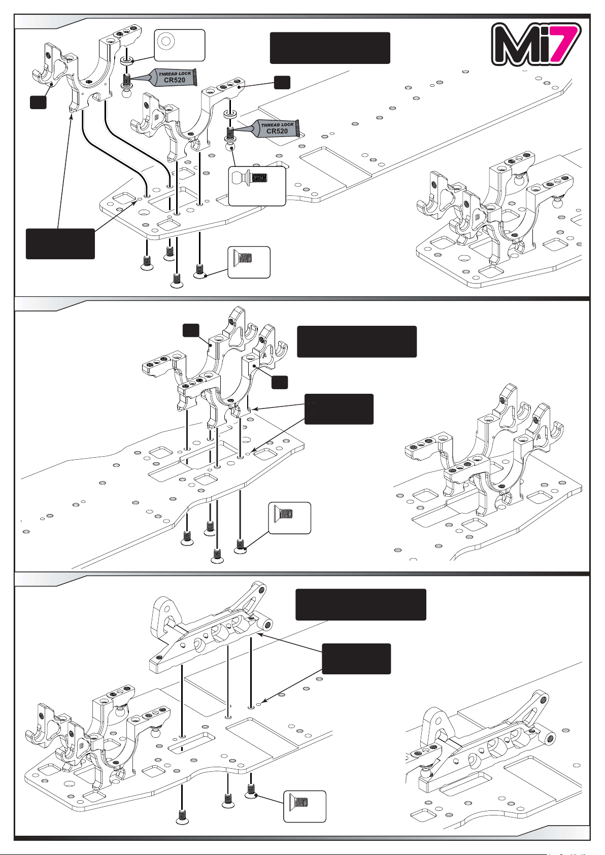
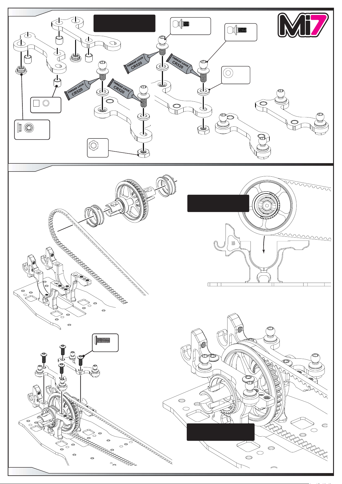
STEP 1
‘A’
The housings
are doweled
into the chassis.
STEP 2
x 2
Black 1.5 mm
The housings may be a tight fit
in the chassis, this is to ensure
accurate alignment.
‘B’
x 2
Black
Ball Stud Short
x 4
M3 x 6
STEP 3
‘B’
The housings may be a tight fit
in the chassis, this is to ensure
accurate alignment.
‘A’
The housings
are doweled
into the chassis.
x 4
M3 x 6
The motor mount may be a tight fit
in the chassis, this is to ensure
accurate alignment.
M3 x 6
The motor mount
is doweled
into the chassis.
x 3
PAGE 2

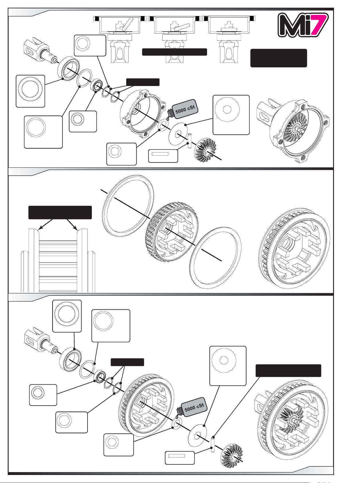
STEP 4
x 1
M3 x 4
The pulley should spin
freely on the shaft.
x 2
Flanged
ø3/16” x ø5/16”
STEP 5
Ensure fence is assembled
as shown.
STEP 6
Use the 5.5mm spanner to
ensure the screw is tight.
The bearings may be a
tight fit on the layshaft.
x 3
Spur Gear Screw
PAGE 3
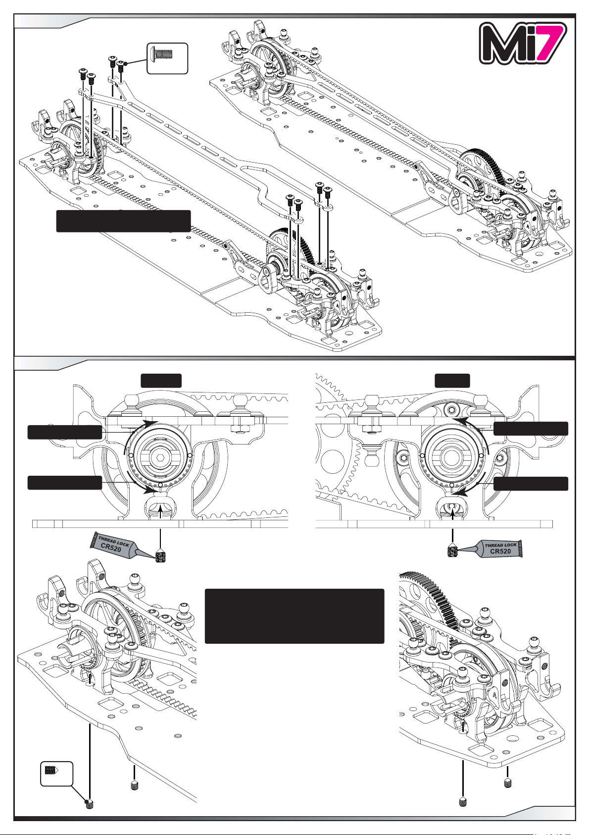
Use the 5.5mm spanner to
ensure the screw is tight.
x 1
M3 x 12
STEP 7
x 1
x 2
ø6.4 x ø8.0 x 0.1
PIN ASSEMBLY PROCEDURE
Use if needed
Use a small amount of oil
to hold all of the parts in
place during assembly.
ø10 x ø15 x 4
STEP 8
x 1
ø5 x ø8 x 2.5
SHIM
ø10 x ø12.5 x 0.10
Ensure fences are assembled
as shown.
x 1
x 1
O’ring ø5 x 1.5
x 1
SHIM
ø5 x ø15 x 0.2
x 1
ø2.0 x 9.8
STEP 9
x 1
ø5 x ø8 x 2.5
x 1
ø10 x ø15 x 4
ø6.4 x ø8.0 x 0.1
SHIM
ø10 x ø12.5 x 0.10
x 2
x 1
Use if needed
x 1
O’ring ø5 x 1.5
ø2.0 x 9.8
x 1
SHIM
ø5 x ø15 x 0.2
x 1
SEE STEP 7 FOR
PIN ASSEMBLY PROCEDURE
PAGE 4
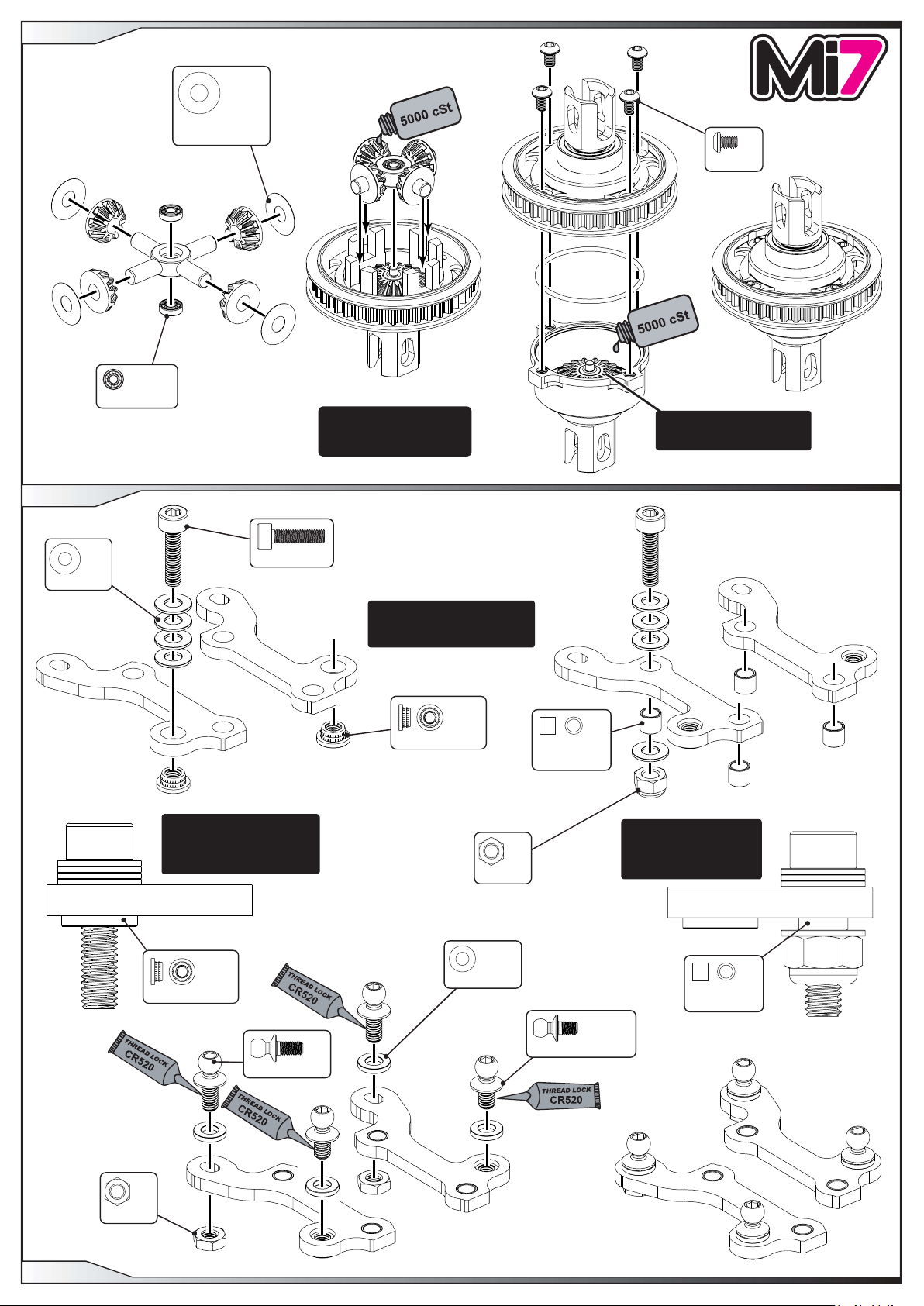
STEP 10
x 2
ø2 x ø5 x 1.5
x 4
SHIM
ø3.5 x ø9.5 x 0.1
Use a small amount of oil
to hold all of the parts in
place during assembly.
x 4
M2.5 x 4
Use 1.6 grams of oil (just
covering the bevel gear).
STEP 11
M3 Washer
x 4
M3 x 12
Tighten the screw until
the M3 thread insert is
pulled into the carbon fibre
part as shown.
x 1
Use the M3x12 cap head
screw and washers to fit the
inserts and dowels.
x 2
M3 Thread Insert
x 1
M3 Nyloc
x 4
Dowel
ø3 x ø4 x 3.5
Tighten the nut until the
dowel is pulled into
the carbon fibre part
as shown.
PAGE 5
M3 Nut
M3 Thread Insert
x 2
Low Ball Short
x 2
x 4
Black 0.5 mm
Dowel
ø3 x ø4 x 3.5
x 2
Low Ball Ultra Short
STEP 12
Make sure the pips on the
eccentric match the image
as shown.
x 4
M3 x 8
STEP 13
STEP 14
The eccentrics are free to rotate.
The belt tension will be set later
when the top deck is fitted.
Ensure fences are assembled
as shown.
x 2
M3 x 8
x 2
ø10 x ø15 x 4
x 2
SHIM
ø10 x ø12.5 x 0.10
PAGE 6
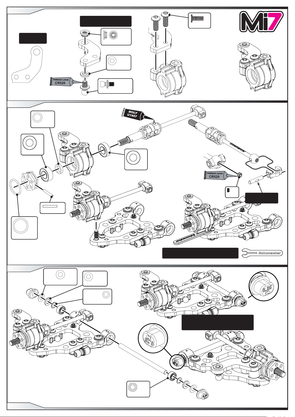
STEP 15
M3 Thread Insert
STEP 16
x 4
ø3 x ø4 x 3.5
x 2
See Page 5 Step 11 for how
to assemble the inserts and
dowels.
x 2
M3 Nut
x 2
Low Ball Ultra Short
x 2
Low Ball Short
x 4
Black 0.5 mm
M3 x 8
Make sure the pips on the
eccentric match the image
as shown.
x 4
PAGE 7
The eccentrics are free to rotate.
The belt tension will be set later
when the top deck is fitted.
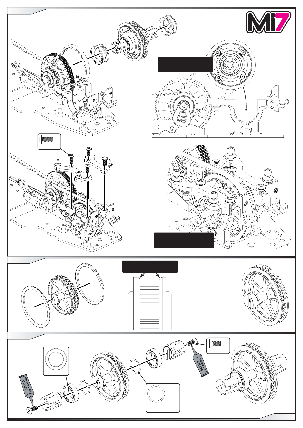
STEP 17
x 8
M3 x 6
Make sure you assemble the top deck
under the front belt. (see final image).
STEP 18
Tighter belt tension.
Looser belt tension.
FRONT REAR
Tighter belt tension.
Looser belt tension.
Set the eccentric position with the grub screw.
IMPORTANT
Make sure both sides are set the same and
only tighten this grub screw when indents
on the eccentrics and housings line up.
DO NOT OVER TIGHTEN
M3 x 4
x 4
PAGE 8
STEP 19
The strap may be a tight fit
in the chassis, this is to ensure
accurate alignment.
Chamfer this side.
x 2
Black 0.5 mm
x 2
M3 x 8
STEP 20
Chamfer this side.
STEP 21
Chamfer this side.
The split blocks may be a tight fit
in the chassis, this is to ensure
accurate alignment.
x 1
Black
Ball Stud Ultra Short
x 4
Black 1.0 mm
x 4
M3 x 6
PAGE 9
x 2
Low Ball Ultra Short
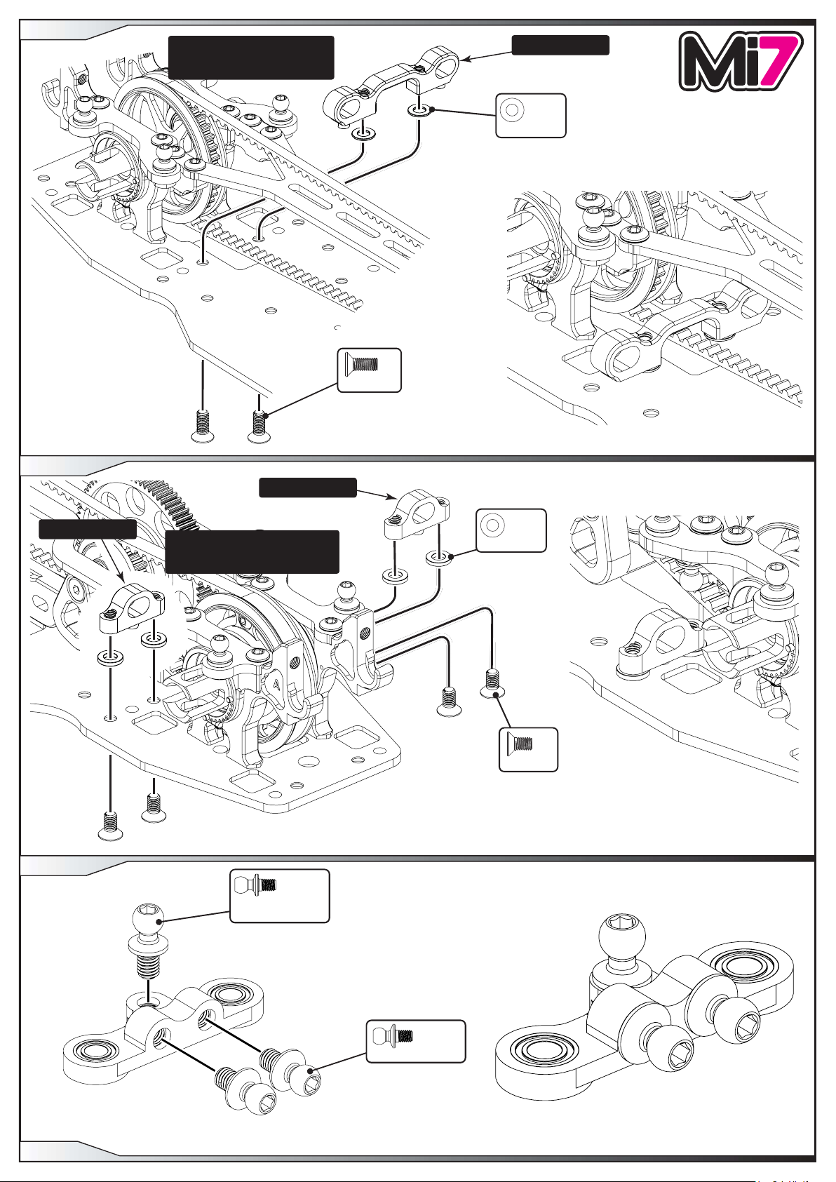
STEP 22
STEP 23
M3 x 4
M3 x 6
x 2
x 2
M3 x 10
x 2
ø3.0 x ø4.5 x 0.25
x 2
ø4 x ø5.65 x 1
Assemble the grub screw central
to the steering lever. See track
settings on how to set this.
x 2
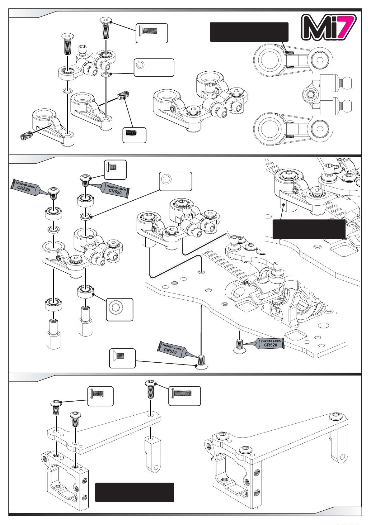
STEP 24
M3 x 6
ø4 x ø8 x 3
M3 x 6
x 2
Ensure the flats on the steering
posts are parallel to the sides
of the chassis.
x 4
x 2
x 1
M3 x 10
The servo mount may be a tight fit
in the servo plate, this is to ensure
accurate alignment.
PAGE 10
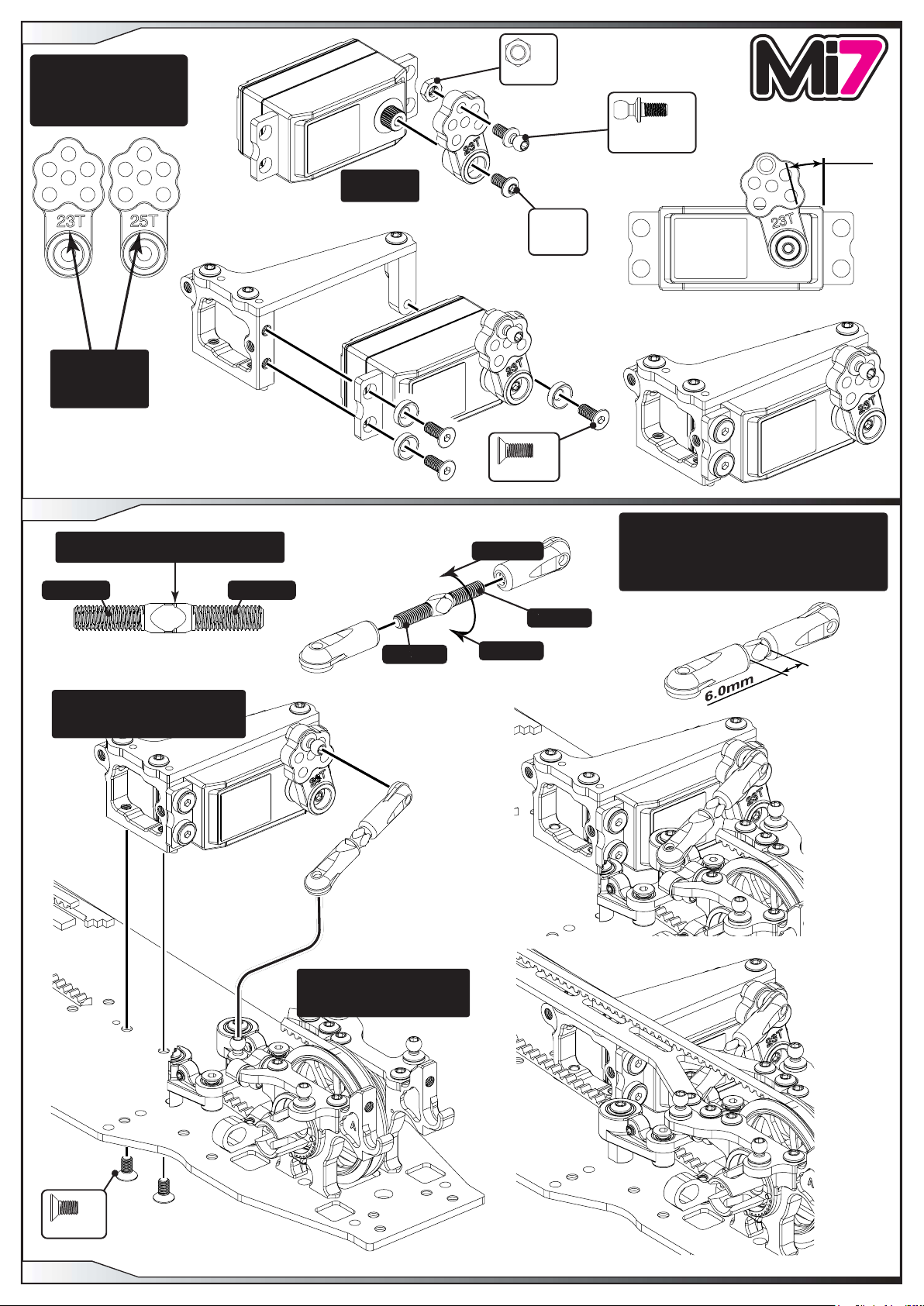
STEP 25
Before you assemble
the servo horn, connect up
your radio gear and set the
steering servo to
neutral.
IMPORTANT
Select the
correct horn for
your servo.
x 1
M3 Nut
x 1
Black
Ball Stud Short
15°
SERVO NOT
INCLUDED
Screw
supplied
with servo
x 3
M3 x 8
STEP 26
Note the shape of the turnbuckle.
This groove indicates the left hand thread.
RH Thread
The servo mount may be a tight
fit in the chassis, this is to ensure
accurate alignment.
LH Thread
RH Thread
Shorter link
Longer link
Carefully screw the sockets onto the turnbuckle
until no threads are visible.
Then undo them to the desired length.
This allows for easier adjustment on the car.
(Greasing the threads will also help)
LH Thread
M3 x 6
PAGE 11
NOTE.
The car has been cut away for
assembly clarification.
x 2

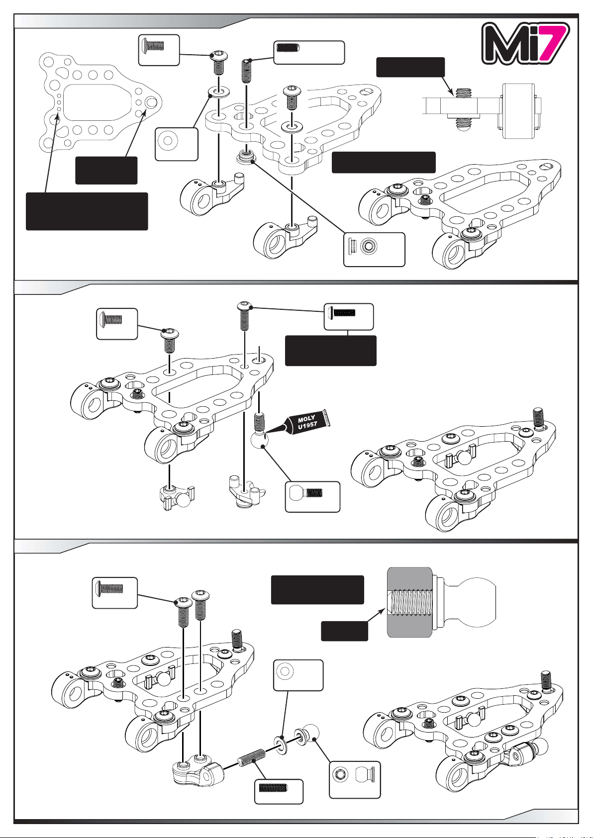
STEP 27 - Right Hand Side Front Suspension
x 2
M3 x 6
M3 Washer
The sphere is
on the bottom
of the wishbone.
IMPORTANT
This is the 3 dot wishbone.
Make sure to use the same
wishbone on both sides of the car.
M3 Thread Insert
See Page 5 Step 11 for how
to assemble the inserts.
STEP 28
x 1
M3 x 8 Dome Ended
x 2
Set the grub screw
central for now.
x 1
Adjust this screw to fine
tune the ball fit.
Do NOT overtighten.
STEP 29
x 1
M3 x 6
M2.5 x 8
Wishbone Ball
x 1
x 1
M3 x 8
x 2
Fit the grub screw into
the moulding first. Then
screw on the shock ball.
Set the grub
screw flush.
Pivot Ball x 1
x 1
Black 0.5 mm
x 1
M3 x 10
PAGE 12
STEP 30
See Page 5 Step 11 for how
to assemble the inserts.
x 2
M3 x 8
Full size front
steering arm.
STEP 31
ø5 x ø10 x 4
x 1
M3 Thread Insert
x 1
Black 1.0 mm
x 1
Low Ball Ultra Short
x 1
ø5 x ø7 x 1.5
x 1
x 1
ø5 x ø10 x 3
O’ring ø9 x 1.0
STEP 32
x 1
ø1.5 x 9.8
x 1
SHIM
ø3.25 x ø6.25 x 0.1
x 2
x 2
Black 1.0 mm
THRUST
x 2
SHIM
ø5 x ø3.25 x 0.3
x 1
M3 x 2
Use the hub height setting tool to
set the gap between the hub and wishbone.
IMPORTANT
Ensure correct orientation of the inserts.
Use 0.25 as the BASE setting.
The flat must face
the grub screw.
PAGE 13
x 2
ø1/8” x ø1/4”
STEP 33 - Left Hand Side Front Suspension
The sphere is
on the bottom
of the wishbone.
IMPORTANT
This is the 3 dot wishbone.
Make sure to use the same
wishbone on both sides of the car.
STEP 34
M3 x 6
x 1
M3 x 6
x 2
x 2
M3 Washer
x 1
M3 x 8 Dome Ended
M2.5 x 8
Adjust this screw to fine
tune the ball fit.
Do NOT overtighten.
Set the grub screw
central for now.
See Page 5 Step 11 for how
to assemble the insert.
x 1
M3 Thread Insert
x 1
STEP 35
M3 x 8
x 2
x 1
Wishbone Ball
Fit the grub screw into
the moulding first. Then
screw on the shock ball.
Set the grub
screw flush.
x 1
Black 0.5 mm
M3 x 10
x 1
Pivot Ball x 1
PAGE 14
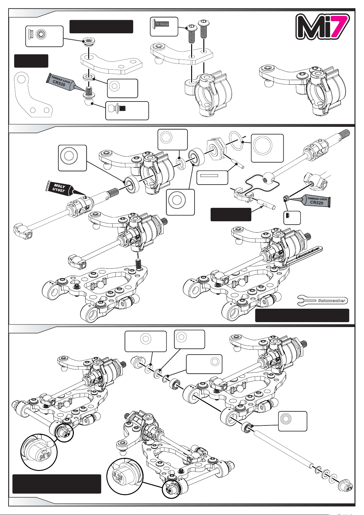
STEP 36
M3 Thread Insert
Full size front
steering arm.
STEP 37
x 1
ø5 x ø10 x 3
See Page 5 Step 11 for how
to assemble the inserts.
Black 1.0 mm
Low Ball Ultra Short
x 1
x 1
x 1
M3 x 8
ø5 x ø7 x 1.5
x 2
x 1
x 1
O’ring ø9 x 1.0
x 1
ø1.5 x 9.8
STEP 38
SHIM
ø3.25 x ø6.25 x 0.1
x 2
x 1
ø5 x ø10 x 4
Black 1.0 mm
The flat must face
the grub screw.
x 2
THRUST
x 2
SHIM
ø5 x ø3.25 x 0.3
x 1
M3 x 2
Use the hub height setting tool to
set the gap between the hub and wishbone.
Ensure correct orientation of the inserts.
IMPORTANT
Use 0.25 as the BASE setting.
PAGE 15
x 2
ø1/8” x ø1/4”
 Loading...