


Schumacher DSR103,DSR103AUX Owner's Manual
Models / Modelos / Modèles :
DSR103, DSR103AUX
Booster
Arrancador
Aide démarrage
OWNERS MANUAL
MANUAL DEL USUARIO
GUIDE D’UTILISATION
DSR103
™
DSR103AUX
PLEASE SAVE THIS OWNER’S MANUAL AND READ BEFORE EACH USE.
This manual will explain how to use the booster and charger safely and effectively.
Please read and follow these instructions and precautions carefully.
POR FAVOR GUARDE ESTE MANUAL DEL PROPIETARIO Y LEER ANTES DE
CADA USO. En este manual se explica cómo utilizar el arrancador y cargador con
seguridad y ecacia. Por favor, lea y siga las siguientes instrucciones y precauciones.
ESSAYER DE GARDER LE MANUEL D’INSTRUCTIONS ET LE LIRE AVANT
CHAQUE UTILISATION. Ce manuel explique comment utiliser l’unité d’une façon
sûre et efcace. S’il vous plaît lisez et suivez ces instructions et précautions.
0099001650-00

1. IMPORTANT SAFETY INSTRUCTIONS
SAVE THESE INSTRUCTIONS.
1.1 SAVE THESE INSTRUCTIONS –
This manual contains important safety
and operating instructions.
WARNING!
RISK OF ELECTRIC SHOCK OR FIRE.
1.2 Read the entire manual before using this
product. Failure to do so could result in
serious injury or death.
1.3 This booster is not intended for use by
persons (including children) with reduced
physical, sensory or mental capabilities,
or lack of experience and knowledge,
unless they have been given supervision or
instruction concerning the use of the booster
by a person responsible for their safety.
1.4 Children should be supervised, to ensure
they do not play with the booster or charger.
1.5 Do not put ngers or hands into the
booster clamps.
1.6 Do not expose the booster to rain or snow.
1.7 Do not operate the booster with damaged
cables or clips; have the cable or clip
replaced immediately a qualied service
person.
1.8 Do not operate the booster if it has
received a sharp blow, been dropped or
otherwise damaged in any way; take it to
a qualied service person.
1.9 Do not disassemble the booster; take it to
a qualied service person when service or
repair is required. Incorrect reassembly may
result in a risk of re or electric shock.
1.10 Use only the included charger for
recharging the booster.
WARNING! RISK OF EXPLOSIVE GASES.
1.11 WORKING IN THE VICINITY OF A
LEAD-ACID BATTERY IS DANGEROUS.
BATTERIES GENERATE EXPLOSIVE
GASES DURING NORMAL BATTERY
OPERATION. FOR THIS REASON, IT IS
OF UTMOST IMPORTANCE THAT YOU
FOLLOW THE INSTRUCTIONS EACH
TIME YOU USE THE BOOSTER.
1.12 To reduce the risk of a battery explosion,
follow these instructions and those
published by the battery manufacturer and
the manufacturer of any equipment you
intend to use in the vicinity of the battery.
Review the cautionary markings on these
products and on the engine.
1.13 This booster employs parts, such as
circuit breakers, that tend to produce arcs
and sparks. If used in a garage, locate
this booster 18 inches (46 cm) or more
above oor level.
1.14 California Proposition 65 Warning:
WARNING: This Product contains
chemicals known to the State of California
to cause cancer and birth defects or other
reproductive harm (California law requires
this warning to be given to customers in
the State of California). Wash hands after
handling.
2. PERSONAL SAFETY PRECAUTIONS
WARNING! RISK OF EXPLOSIVE
GASES. A SPARK NEAR THE BATTERY
MAY CAUSE A BATTERY EXPLOSION.
TO REDUCE THE RISK OF A SPARK
NEAR THE BATTERY:
2.1 NEVER smoke or allow a spark or ame
in the vicinity of a battery or engine.
2.2 Remove personal metal items such as
rings, bracelets, necklaces and watches
when working with a lead-acid battery.
A lead-acid battery can produce a
short-circuit current high enough to weld
a ring or the like to metal, causing a
severe burn.
2.3 Be extra cautious, to reduce the risk of
dropping a metal tool onto the battery. It
might spark or short-circuit the battery or
other electrical part that may cause an
explosion.
2.4 Do not permit the internal battery of the
booster to freeze. Never charge a
frozen battery.
• 2 •
2.5 To prevent sparking, NEVER allow clips to
touch together or contact the same piece
of metal.
2.6 Consider having someone nearby to
come to your aid when you work near a
lead-acid battery.
2.7 Have plenty of fresh water and soap
nearby in case battery acid contacts your
skin, clothing or eyes.
2.8 Wear complete eye and body protection,
including safety goggles and protective
clothing. Avoid touching your eyes while
working near the battery.
2.9 If battery acid contacts your skin or
clothing, immediately wash the area
with soap and water. If acid enters your
eye, immediately ood the eye with cold
running water for at least 10 minutes and
get medical attention right away.
2.10 If battery acid is accidentally swallowed,
drink milk, the whites of eggs or water.
DO NOT induce vomiting. Seek medical
attention immediately.
3. PREPARING TO USE THE BOOSTER
IMPORTANT: AFTER PURCHASE,
CHARGE YOUR BOOSTER FOR
24 HOURS, BEFORE USE.
WARNING! RISK OF CONTACT WITH
BATTERY ACID. BATTERY ACID IS A
HIGHLY CORROSIVE SULFURIC ACID.
3.1 Be sure the area around the battery is well
ventilated while the booster is being used.
3.2 Clean the battery terminals before using
the booster. During cleaning, keep
airborne corrosion from coming into
4. BOOSTER LOCATION
WARNING! RISK OF EXPLOSION
AND CONTACT WITH BATTERY ACID.
4.1 Locate the booster as far away from the
battery as the DC cables permit.
5. INSTALLATION INSTRUCTIONS
5.1 Remove all cord wraps and uncoil the cables
prior to using the charger and booster.
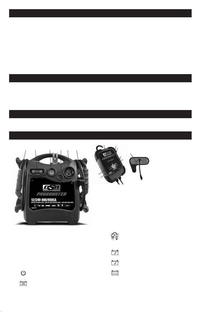
6. FEATURES
1 2 3 4 5 6
contact with your eyes, nose and mouth.
Use baking soda and water to neutralize
the battery acid and help eliminate
airborne corrosion. Do not touch your
eyes, nose or mouth.
3.3 Determine the voltage of the battery by
referring to the vehicle owner’s manual
and make sure that the output voltage of
the booster is correct.
3.4 Make sure that the booster cable clips
make tight connections.
4.2 Never place the booster directly above
the battery being jumped; gases from the
battery will corrode and damage the booster.
4.3 Do not operate the booster in a closed-in
area or restrict the ventilation in any way.
5.2 After purchase, charge your booster for
24 hours, before use.
8
9
10
15
11
12
™
6.1 CHARGER
Start/Stop Button
Press to immediately begin charging your
properly connected battery. If the button
is not pressed, charging should begin
in ten minutes.
LED Indicators
POWER (green) LED lit: The
charger is connected to AC power.
BAD BATTERY (red) LED:
The charger has detected a problem
with the battery. See Troubleshooting
for more information.
14
13
1. Battery clamps
2. 500A internal fuses
3. Alarm
4. Voltmeter button
5. Voltmeter
6. Auxiliary cable port
(DSR103AUX only)
7. Auxiliary charging port
(on back; not shown)
CLAMPS REVERSED (red) LED
ashing:The connections are
reversed.
CHARGING (yellow/orange) LED lit:
The charger is charging the battery.
CHARGING (yellow/orange) LED
ashing: The charger is in abort mode.
CHARGED/MAINTAINING (green)
LED pulsing: The battery is fully
charged and the charger is in
maintain mode.
NOTE: See Operating Instructions for a
complete description of the charger modes.
• 3 •
8. SC3DSR charger
9. Power LED
10. Start/Stop button
11. Clamps Reversed LED
12. Bad Battery LED
13. Charging LED
14. Charged/Maintaining LED
15. Charger plug
7. CHARGING THE INTERNAL BATTERY OF THE BOOSTER
• Press the Voltmeter button to show the
charge level of the battery.
• After starting the engine at 2000 rpm,
leave the booster connected to the
vehicle and press the voltmeter button.
The voltmeter will indicate between
14 and 14,4 volts (at 2000 rpm) if the
alternator is functioning correctly.
7.1 Grounding and AC Power Cord
Connections
IMPORTANT. Only use the charger that
was included with the booster to charge
the internal battery of the booster. Using a
different charger could result in personal
injury or property damage.
WARNING!
RISK OF ELECTRIC SHOCK OR FIRE.
This battery charger is for use on a
nominal 120V circuit. The plug must be
plugged into an outlet that is properly
installed in accordance with all local
codes and ordinances. The plug pins
must t the receptacle (outlet). Do not use
with an ungrounded system.
DANGER. Never alter the AC cord or plug
provided – if it does not t the outlet, have
a proper outlet installed by a qualied
electrician. An improper connection can
result in a risk of an electric shock or
electrocution.
An extension cord should not be used
unless absolutely necessary. Use of an
improper extension cord could result
in a risk of re and electric shock. If an
extension cord must be used, make sure:
• That the pins on the plug of the extension
cord are the same number, size and
shape as those of the plug on the
charger.
• That the extension cord is properly wired
and in good electrical condition.
• That the wire size is large enough for the
AC ampere rating of the charger,
as specied:
Length of cord (feet) 25 50 100 150
AWG* size of cord 18 18 18 16
*AWG-American Wire Gauge
7.2 Charging the Booster
1. Connect the end of the charger quick-
connect to the charger.
2. Insert the charge plug into the charge
port on the back of the booster.
3. Plug the charger’s power cord into
a grounded 120V AC electrical wall
outlet.
4. The charger’s green POWER LED
will light.
5. Charging will begin within ten minutes
and nish automatically. (Press the
Start/Stop button to begin charging
immediately.)
6. The pulsing green LED indicates the
battery is fully charged.
7. When charging is complete,
disconnect the charger from the AC
power. Then remove the charging plug
from the booster.
7.3 Charger Modes
Automatic charging mode
When an automatic charge is performed,
the charger switches to maintain mode
automatically after the battery is charged.
Aborted Charge
If charging cannot be completed normally,
charging will abort. When charging aborts,
the charger’s output is shut off. The BAD
BATTERY (red) LED will light, and
the CHARGING (yellow/orange) LED
will ash. Do not continue attempting to
charge this battery. Check the battery and
replace, if necessary.
Desulfation Mode
Desulfation could take 8 to 10 hours. If
desulfation fails, charging will abort. The
BAD BATTERY (red) LED will light,
and the CHARGING (yellow/orange)
LED will ash.
Completion of Charge
Charge completion is indicated by the
CHARGED/MAINTAINING (green)
LED. When pulsing, the charger has
switched to Maintain Mode.
Maintain Mode (Float-Mode Monitoring)
When the green (CHARGED) LED is
pulsing, the charger has started maintain
mode. In this mode, the charger keeps the
battery fully charged by delivering a small
current when necessary. If the charger
has to provide its maximum maintain
current for a continuous 12 hour period,
it will go into abort mode (see Aborted
Charge). This is usually caused by a
drain on the battery or the battery could
be bad. Make sure there are no loads on
the battery. If there are, remove them. If
there are none, have the battery checked
or replaced.
• 4 •

Maintaining the Battery
The SC3DSR maintains 12V batteries,
keeping them at full charge.
NOTE: The maintain mode technology
allows you to safely charge and maintain
a healthy battery for extended periods
8. OPERATING INSTRUCTIONS
IMPORTANT: READ INSTRUCTIONS
BEFORE CONNECTING THE OUTPUT
VOLTAGE SELECTOR.
8.1 Voltage detection system
Your Booster is equipped with a voltage
detection system. After the connection of
the clamps on the battery terminals of the
vehicle, LEDs will indicate its voltage, as
follows:
• The green LED next to the 12V
connector lights up when the voltage
detected by the Booster is between 3V
and 14,4V.
• The orange LED next to the 24V
connector lights up when the voltage
detected by the Booster is over 14,4V.
NOTE: If your vehicle does not start when
the Booster is connected in 12V, your
vehicle may start in 24V:
• When its voltage is under 14,5V
• If you connected the Booster on the
wrong vehicle’s battery
8.2 Detection of 24V
Detection of 24 volt on a vehicle where
the cables are not visible or when the
batteries are located on both sides of
the engine bay (construction, agriculture,
military or other large type engines).
Use a voltmeter in DC position:
Connect the negative to the mass of the
vehicle and the positive to the positive of
a battery.
• If the voltmeter indicates 12V, you are not
on the right battery.
• If the voltmeter indicates 24V, you are on
the right battery.
8.3 Selecting the voltage
1. Determine voltage of vehicle battery.
(Refer to the vehicle instruction manual.)
2. Make sure to plug the output voltage
selector into the correct connector.
of time. However, problems with the
battery, improper connections or other
unanticipated conditions could cause
excessive current draws. Occasionally
monitoring your battery and the charging
process is recommended.
8.4 Jump Starting a Vehicle Engine
IMPORTANT: Using the booster without a
battery installed in the vehicle will damage
the vehicle’s electrical system.
IMPORTANT: Do not use the booster while
charging its internal battery.
WARNING! A SPARK NEAR THE
BATTERY MAY CAUSE A BATTERY
EXPLOSION. TO REDUCE THE RISK
OF A SPARK NEAR THE BATTERY:
1. Turn the vehicle’s ignition OFF before
making cable connections.
2. Position the DC cables to reduce the
risk of damage by the hood, door and
moving or hot engine parts.
NOTE: If it is necessary to close the
hood during the jump starting process,
ensure that the hood does not touch
the battery clips or cut the insulation of
the cables.
3. Stay clear of fan blades, belts, pulleys
and other parts that can cause injury.
4. Check the polarity of the battery posts.
The POSITIVE (POS, P, +) battery
post usually has a larger diameter
than the NEGATIVE (NEG, N, -) post.
5. Determine which post of the battery is
grounded (connected) to the chassis.
If the negative post is grounded to the
chassis (as in most vehicles), see step
6. If the positive post is grounded to
the chassis, see step 7.
6. For a negative-grounded vehicle,
connect the POSITIVE (RED) clip from
the booster to the POSITIVE (POS,
P, +) ungrounded post of the battery.
Connect the NEGATIVE (BLUE) clip
to the vehicle chassis or engine block
away from the battery. Do not connect
the clip to the carburetor, fuel lines or
sheet-metal body parts. Connect to a
heavy gauge metal part of the frame
or engine block.
7. For a positive-grounded vehicle,
connect the NEGATIVE (BLUE) clip
from the booster to the NEGATIVE
(NEG, N, -) ungrounded post of the
battery. Connect the POSITIVE (RED)
clip to the vehicle chassis or engine
block away from the battery. Do not
connect the clip to the carburetor,
fuel lines or sheet-metal body parts.
• 5 •

Connect to a heavy gauge metal part
of the frame or engine block.
8. If the batteries are side by side:
Connect the red clamp (+) to the
positive terminal (+) of the battery, and
then connect the blue clamp (-) to the
negative (-) terminal of the other battery.
9. If the batteries are on both sides
of the vehicle: Connect the red clamp
(+) to the positive terminal (+) of the
battery, and then connect the blue
clamp (-) to the mass of the vehicle.
10. Connect the output voltage selector.
12V
24V
11. Crank the engine. If the engine does not
start within 8-10 seconds, stop cranking
and wait at least 3 minutes before
attempting to start the vehicle again.
• To allow the voltage of the booster
battery to build up again.
• To allow the renewal of gases inside
the battery.
• To allow the internal components of
the battery to cool down.
If you do not wait and/or the starting
attempt is too long, you risk losing power,
you reduce your starting possibilities by
the second attempt and you risk melting
the fuse inside.
IMPORTANT:
• Never connect the booster to a battery
or starter which is in short-circuit. The
internal fuse will blow.
• Make sure clamps are connected
correctly.
• Never disconnect the booster while
engine running when there is no
battery in the vehicle or when the
vehicle’s battery is at 0 volt. This may
damage the alternator.
12. After the engine starts, disconnect
the output voltage selector.
Then, disconnect the blue clamp (-)
and the red clamp, (+) in that order.
13. Return the cables and clamps to their
support posts.
14. Immediately recharge the booster.
8.5 Indication of polarity inversion
If the polarity is incorrect, the alarm will sound:
• If the remaining voltage in the batteries
of the vehicle is at least 4 volts
• If the output voltage selector is not
connected
8.6 Internal fuse replacement
The booster is equipped with an internal
fuse. It can melt following a short circuit or
a too-long start attempt.
To monitor the fuse:
• Press on the voltmeter. If it does not
deviate, the fuse has melted.
• Measure the voltage at the clamps:
0 volt = melted fuse.
Fusespecication
AMG Heavy Duty 500A
WARNING! KEEP AWAY FROM SPARKS
AND FLAMES – BATTERY COULD EMIT
EXPLOSIVE GASES.
1. Allow the fuse to cool down
completely (approximately 5 minutes).
2. Make sure the unit is unplugged from
the external charger.
3. Remove the positive (RED) clamp
from the storage compartment on the
side of the unit and locate the fuse
holder.
4. Open the fuse holder by removing its
cover.
5. Using a wrench, remove the rst nut
and bolt securing the fuse on the
positive cable. Repeat the same steps
for the second nut and bolt. Remove
the open fuse and replace it with a
new one of the same type and rating.
6. Tighten the nuts and bolts to secure
the fuse, and then replace the cover of
the fuse holder.
7. The unit is now ready to use.
8.7 Use of Auxiliary DC Cables
(DSR103AUX Only)
The booster is equipped with an auxiliary
DC cable connection. This connection is
only to be used with DSR Auxiliary DC
Cables.
IMPORTANT: Using the booster without a
battery installed in the vehicle will damage
the vehicle’s electrical system.
IMPORTANT: Do not use the booster
while charging its internal battery.
IMPORTANT: Do not use the built-in
DC cables of the jump starter and the
auxiliary DC cable at the same time.
WARNING! A SPARK NEAR THE
BATTERY MAY CAUSE A BATTERY
EXPLOSION. TO REDUCE THE RISK
OF A SPARK NEAR THE BATTERY:
1. Turn the vehicle’s ignition OFF before
making cable connections.
2. Position the AUXILIARY DC cables to
reduce the risk of damage by the hood,
door and moving or hot engine parts.
• 6 •

NOTE: If it is necessary to close the
hood during the jump starting process,
ensure that the hood does not touch
the AUXILIARY DC cables or cut the
insulation of the cables. Review the
instructions included with the auxiliary DC
cable before proceeding.
3. Stay clear of fan blades, belts, pulleys
and other parts that can cause injury.
4. Determine the location of the auxiliary
cable connection on the vehicle.
5. Remove the cover from the auxiliary DC
cable connection on the jump starter.
6. Insert the auxiliary DC cable into the
connection of the jump starter.
7. Insert the auxiliary DC cable into the
connection of the vehicle.
8. Connect the output voltage selector.
12V
24V
9. Crank the engine. If the engine does not
start within 8-10 seconds, stop cranking
and wait at least 3 minutes before
attempting to start the vehicle again.
• To allow the voltage of the booster
battery to build up again.
• To allow the renewal of gases inside
the battery.
• To allow the internal components of
the battery to cool down.
If you do not wait and/or the starting
attempt is too long, you risk losing power,
you reduce your starting possibilities by
the second attempt and you risk melting
the fuse inside.
IMPORTANT:
• Never connect the booster to a battery
or starter which is in short-circuit. The
internal fuse will blow.
• Make sure clamps are connected
correctly.
• Never disconnect the booster while
engine running when there is no
battery in the vehicle or when the
vehicle’s battery is at 0 volt. This may
damage the alternator.
10. After the engine starts, disconnect
the output voltage selector. Then,
disconnect the auxiliary DC cable from
the vehicle and then the jump starter.
Insert the cover into the auxiliary DC
cable connection on the jump starter.
11. Immediately recharge the booster.
9. MAINTENANCE INSTRUCTIONS
9.1 After use and before performing
maintenance, unplug and disconnect the
booster.
9.2 Use a dry cloth to wipe all battery corrosion
and other dirt or oil from the battery clips,
cords, and the booster’s case.
9.3 Ensure that all of the booster’s
9.4 All servicing should be performed by
10. MOVING AND STORAGE INSTRUCTIONS
10.1 IMPORTANT:
• CHARGE IMMEDIATELY AFTER
PURCHASE
• KEEP FULLY CHARGED
The internal battery will gradually
self-discharge (lose power) over time,
especially in warm environments. Leaving
the battery in a discharged state may
result in permanent battery damage.
10.2 Store inside, in a cool, dry place.
The ideal storage temperature is between
50°-77°F (0°-25°C).
10.3 Clamps must be stored on their support
10.4 If the booster is moved around the shop
• 7 •
components are in place and in good
working condition, including the plastic
boots on the battery clips.
qualied service personnel.
posts, to make sure they do not come to
contact with any metallic surface.
or transported to another location, take
care to avoid/prevent damage to the
cords, clips and the unit. Failure to do so
could result in personal injury or property
damage.
IMPORTANT: Do not use and/or store
the booster in or on any area or surface
where damage could occur if the internal
battery should unexpectedly leak acid.

11. SPECIFICATIONS
Booster
Internal battery type ....................................................Maintenance-free AGM lead-acid
Nominal voltage .......................................................................................... 12V/24V DC
Capacity ........................................................................................................... 2 x 32 Ah
Peak amps, 12V...................................................................................................... 6400
Peak amps, 24V...................................................................................................... 3200
Cranking amps, 12V ................................................................................................. 900
Cranking amps, 24V ................................................................................................. 650
Cold cranking amps, 12V .......................................................................................... 690
Cold cranking amps, 24V .......................................................................................... 420
Jumper cables.........................................................................................50 mm2, 53.15"
Dimensions ......................................................................... 19.29 x 7.48 x 19.69 inches
Weight .............................................................................................57.43 lbs. (26.05 kg)
Charger
Input Voltage. .............................................................................120V AC @ 60Hz, 2.2A
Output Voltage ..........................................................................................................12V
Output Current Rating ..................................................................................... 8A @ 12V
12. REPLACEMENT PARTS
Booster
Meter ......................................................................................................... 5399200032Z
Push button ............................................................................................... 0499000177Z
Internal battery (12V, 32Ah) ...................................................................... 5799000042Z
Battery clamps .......................................................................................... 2299002913Z
Fuse (AMG heavy-duty, 500A) .................................................................. 3999002114Z
Charger
SC3DSR charger ...................................................................................... 2299002873Z
Plug kit. ..................................................................................................... 2299002914Z
13. TROUBLESHOOTING
Booster
PROBLEM REASON SOLUTION
The booster does not recharge. The AC outlet is dead.
Poor electrical connection.
The booster is not connected
correctly.
The battery is bad.
• 8 •
Check for open fuse or circuit
breaker supplying AC outlet.
Check power cord and extension
cord for a loose tting plug.
Verify the connections from the
station’s charging plug to the
vehicle’s battery.
Replace the battery.
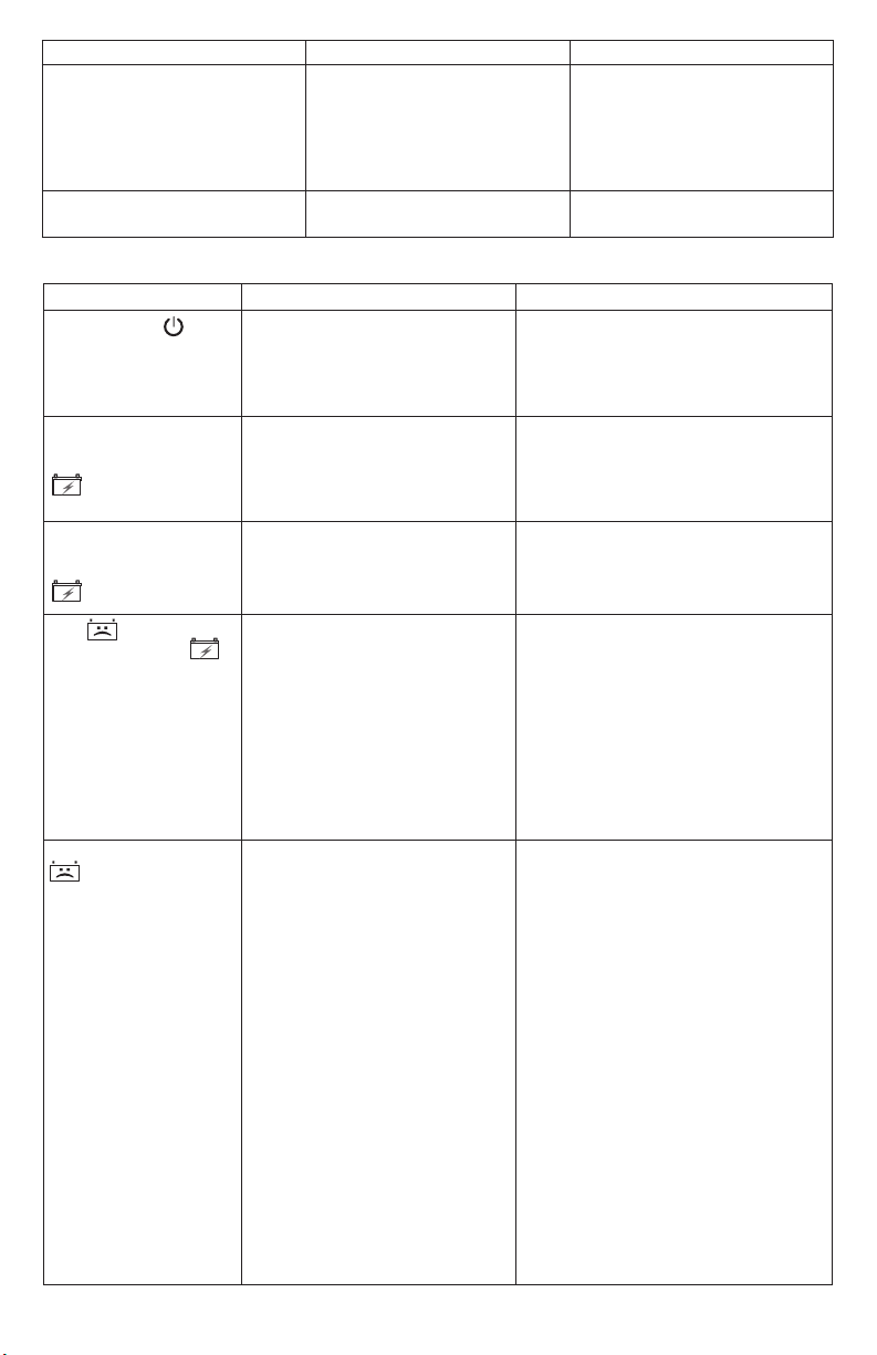
PROBLEM REASON SOLUTION
The Booster has no power. The booster’s battery is not
charged.
Check the battery charge
status by pressing the
Voltmeter button. Recharge the
battery.
The battery in the booster won’t
hold a charge.
The internal fuse has blown.
The battery is bad (will not
accept a charge).
Replace the fuse.
Replace the battery.
Charger
PROBLEM POSSIBLE CAUSE SOLUTION
The POWER LED
does not light when
charger is properly
connected.
The battery is
correctly connected,
but the CHARGING
AC outlet is dead.
Poor electrical connection.
If the START/STOP button is
not pressed, charging should
begin in ten minutes.
Check for open fuse or circuit
breaker supplying AC outlet.
Check power cord and extension
cord for a loose tting plug.
No problem; this is normal.
LED did not light
immediately.
The battery is
properly connected,
The battery voltage is low. Press the START/STOP button to
start charging.
but the CHARGING
LED never lit.
The LED is lit and
the CHARGING
LED is ashing.
The battery voltage is still below
10V after 2 hours of charging.
(or)
The battery may be defective. Make
sure there are no loads on the battery.
If there are, remove them. If there are
none, have the battery checked or
replaced.
In maintain mode, the output
current is more than 1.5A for
12 hours.
Desulfation was unsuccessful.
The battery may be defective. Have
battery checked or replaced.
The BAD BATTERY
LED is lit.
The battery is sulfated.
The charger is in desulfation mode.
Continue charging for several hours.
If not successful, have the battery
checked.
Lack of progress is detected and
battery voltage is below 14.2V.
The battery’s initial voltage is
below 12.2V and the total input
is less than 1.5 Ah.
The battery voltage drops to
below 12.2V in Maintain Mode.
• 9 •
The battery may be overheated. If
so, allow the battery to cool. The
battery may be too large or have a
short circuit. Have battery checked
or replaced.
The battery capacity is too low, or the
battery is too old. Have it checked or
replaced.
The battery won’t hold a charge.
May be caused by a drain on the
battery or the battery could be bad.
Make sure there are no loads on the
battery. If there are remove them.
If there are none, have the battery
checked or replaced.

14. BEFORE RETURNING FOR REPAIRS
For more information about troubleshooting,
contact customer service for assistance:
services@schumacherelectric.com
www.batterychargers.com
or call 1-800-621-5485
Monday-Friday 7:00am to 5:00pm CST
For REPAIR OR RETURN, contact Customer Service at 1-800-621-5485.
DO NOT SHIP UNIT until you receive a RETURN MERCHANDISE AUTHORIZATION
(RMA) number from Customer Service at Schumacher Electric Corporation.
15. LIMITED WARRANTY
SCHUMACHER ELECTRIC CORPORATION, 801 BUSINESS CENTER DRIVE,
MOUNT PROSPECT, IL 60056-2179, MAKES THIS LIMITED WARRANTY TO THE
ORIGINAL RETAIL PURCHASER OF THIS PRODUCT. THIS LIMITED WARRANTY
IS NOT TRANSFERABLE OR ASSIGNABLE.
Schumacher Electric Corporation (the “Manufacturer”) warrants this booster and
charger for one (1) year from the date of purchase at retail against defective material
or workmanship that may occur under normal use and care. If your unit is not free from
defective material or workmanship, Manufacturer’s obligation under this warranty is
solely to repair or replace your product, with a new or reconditioned unit, at the option
of the Manufacturer. It is the obligation of the purchaser to forward the unit, along with
proof of purchase and mailing charges prepaid to the Manufacturer or its authorized
representatives in order for repair or replacement to occur.
Manufacturer does not provide any warranty for any accessories used with this product
that are not manufactured by Schumacher Electric Corporation and approved for use with
this product. This Limited Warranty is void if the product is misused, subjected to careless
handling, repaired, or modied by anyone other than Manufacturer or if this unit is resold
through an unauthorized retailer.
Manufacturer makes no other warranties, including, but not limited to, express, implied or
statutory warranties, including without limitation, any implied warranty of merchantability or
implied warranty of tness for a particular purpose. Further, Manufacturer shall not be liable
for any incidental, special or consequential damage claims incurred by purchasers, users
or others associated with this product, including, but not limited to, lost prots, revenues,
anticipated sales, business opportunities, goodwill, business interruption and any other
injury or damage. Any and all such warranties, other than the limited warranty included
herein, are hereby expressly disclaimed and excluded. Some states do not allow the
exclusion or limitation of incidental or consequential damages or length of implied warranty,
so the above limitations or exclusions may not apply to you. This warranty gives you specic
legal rights and it is possible you may have other rights which vary from this warranty.
THIS LIMITED WARRANTY IS THE ONLY EXPRESS LIMITED WARRANTY AND THE
MANUFACTURER NEITHER ASSUMES OR AUTHORIZES ANYONE TO ASSUME
OR MAKE ANY OTHER OBLIGATION TOWARDS THE PRODUCT OTHER THAN
THIS WARRANTY.
Schumacher® and the Schumacher logo are registered trademarks
of Schumacher Electric Corporation.
• 10 •