


Schumacher CAT XLS Masami Instruction Manual
S1422-ISS1
71-73 Tenter Road
Moulton Park
Northampton
NN3 6AX
U.K.
Instruction Manual

Schumacher Racing stocks and
distributes the following
manufacturers products and full
product listings are
available on our website at
www.racing-cars.com
PLEASE NOTE THAT SOME OF THE
PRODUCT RANGES BELOW ARE ONLY
AVAILABLE IN THE UNITED KINGDOM.
IMPORTANT SAFETY NOTES
This product is not suitable for children under the age of 14, without the direct
supervision of a responsible adult.
Select an area for assembly that is away from the reach of small children.
The parts in this kit are small and can be swallowed by children causing choking
and possible internal injuries.
Exercise care when using hand tools and sharp instruments during assembly.
Carefully read all manufacturers warnings and cautions for any additional items
used in the construction.
In line with our policy of continuous development the exact details of the kit may vary.
DO NOT use this car on public roads or in places where it can interfere with
traffic, people or animals.
Always check the operation of the radio with the wheels off the ground, before
using the car.
Make sure the radio and car batteries are fully charged before use.
Disconnect and remove the battery from the car when not in use.
Always store and charge LiPo batteries in a fireproof container.
DO NOT put fingers or any objects inside rotating or moving parts as this may
cause injury.
Make sure the charger is correctly set for the type of battery you are using.
Incorrect charging may cause a fire.
Insulate all exposed electrical wiring. Exposed or damaged wires can cause
short circuits and fire.
The motor and speed controller can become hot during use.
DO NOT touch them immediately after using your car as this may cause injury.
Serrated Pliers
Pinion
Curved Body Scissors
Solder
Soldering Iron
Steel Spanner - 5.50mm
Steel Spanner - 4.00mm
Steel Spanner - 1/4”
Body Reamer
M3 Nut Driver
Hex Driver - 1.5mm
Hex Driver - 2.0mm
Hex Driver - 2.5mm
Phillips Screwdriver 4.0x120mm
Turnbuckle Wrench 4mm
Radio Transmitter and Receiver
(Batteries not included)
Battery Charger
Electronic Speed Controller
2S Shorty LiPo Battery
or
Traditional Stick Pack Battery NiMh or LiPo
IMPORTANT MOTOR LIMITATIONS
17.5 BRUSHLESS FOR STANDARD CAR
6.5 BRUSHLESS FOR PRO TRANSMISSION UPGRADE
Servo
Super Glue and Threadlock
Polycarbonate
Paint
Circlip Pliers
SEE PAGES 29 & 30 FOR COMPLETE TOOLS LISTINGS
LC RACING
ADDITIONAL ITEMS REQUIRED (See Spares Listings in the Manual)
PAGE 1
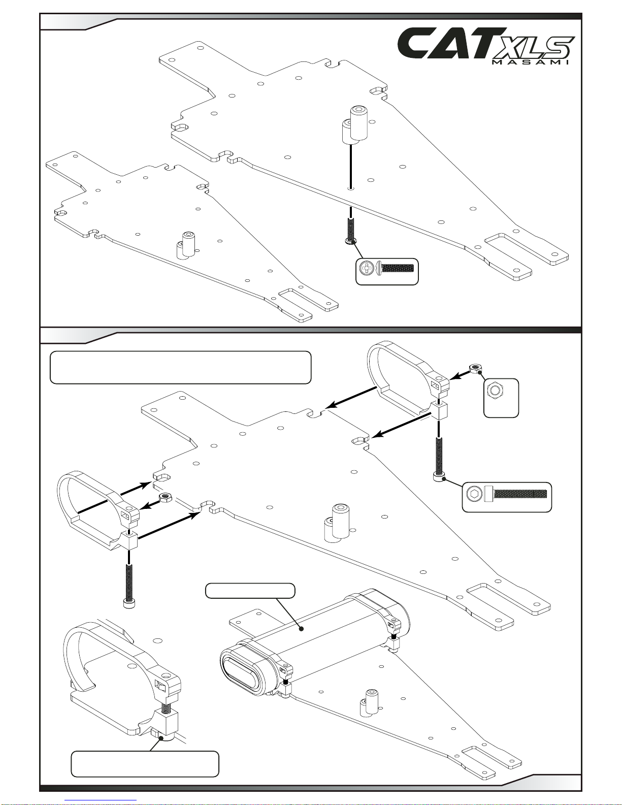
Tighten and loosen these screws
to open and close the battery clamps.
Battery not included.
M3 x 12 x 1
M3 x 20 x 2
M3 Nut
Steel
x 2
Traditional stick pack option. (INCLUDED IN KIT)
(See also STEP 3)
STEP 1
PAGE 2
STEP 2
8.00mm
Battery not included.
Shorty LiPo option.
(INCLUDED IN KIT)
(See also STEP 2)
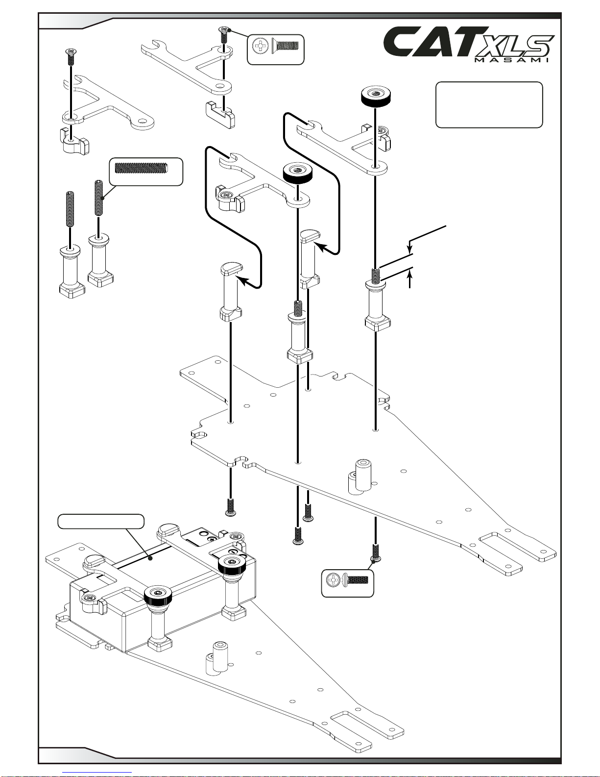
M4 x 20
x 2
M3 x 8
x 2
M3 x 8 x 4
STEP 3
PAGE 3
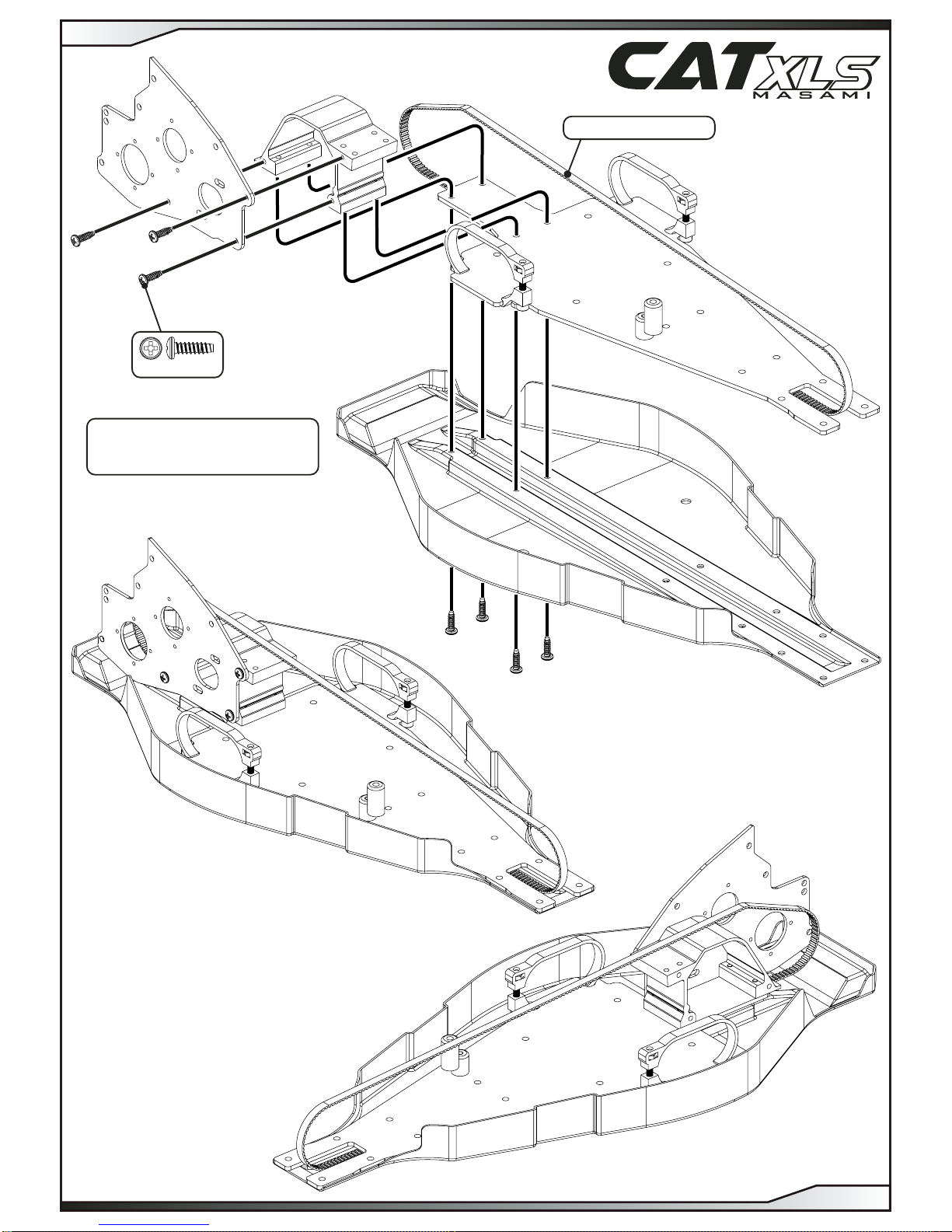
Cut out the undertray as
shown before assembly.
No4 x 3/8” x 7
Assemble belt as shown.
STEP 4
PAGE 4
Set the eccentric as shown for now.
No2 x 3/16” x 8
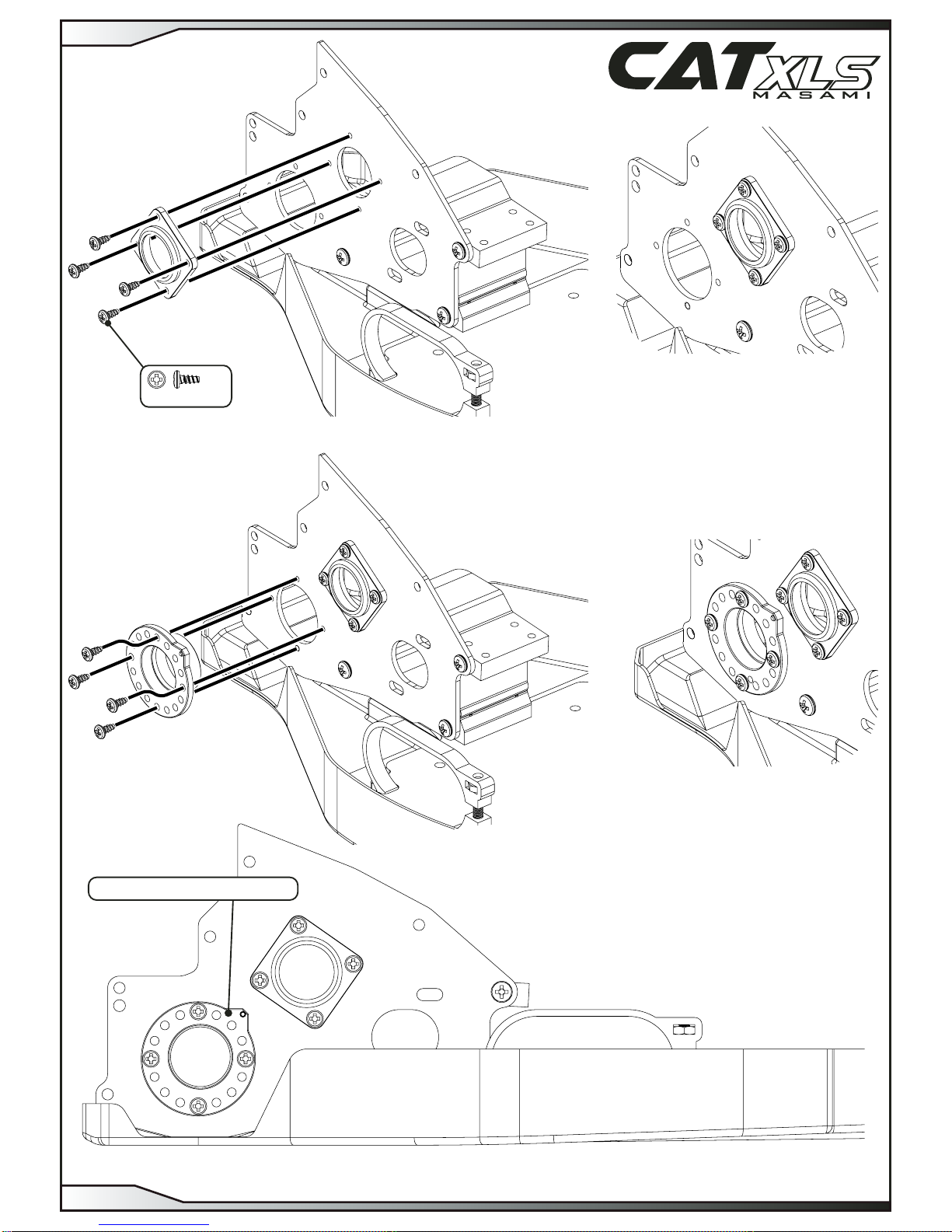
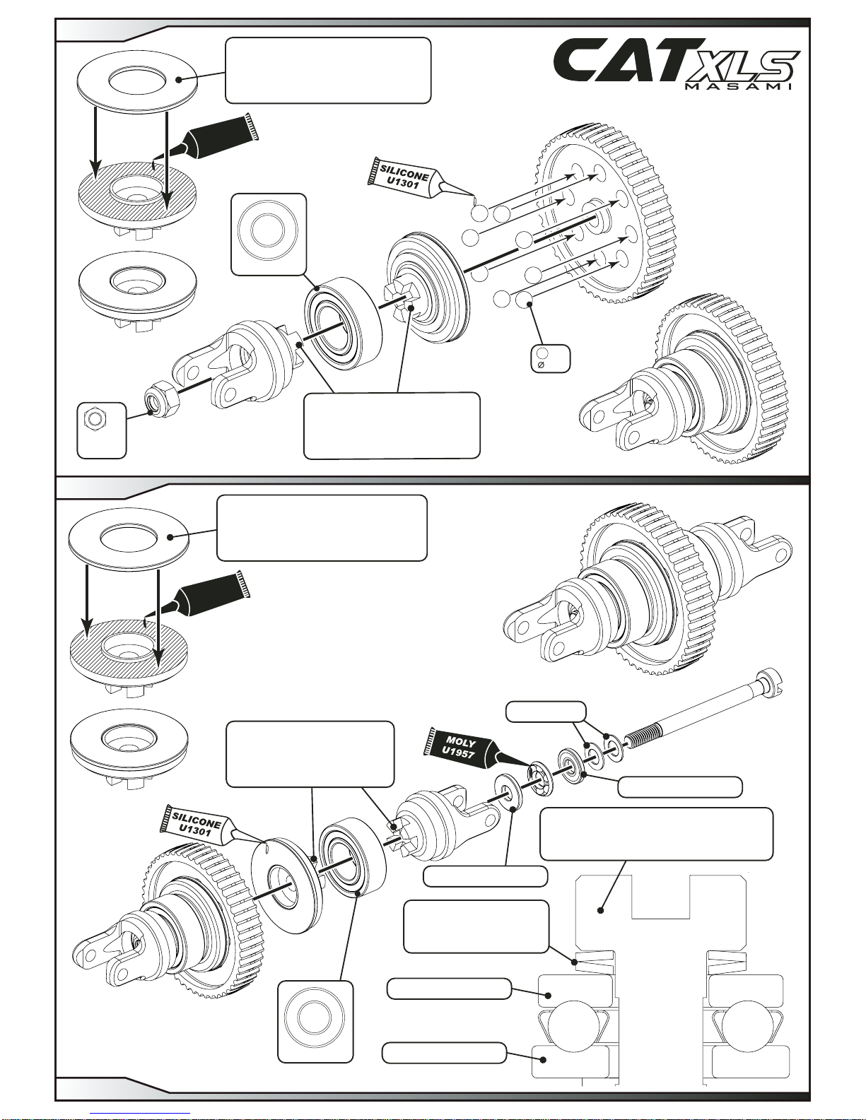
STEP 5
PAGE 5
Super Glue
H1057
Super Glue
H1057
Super Glue
H1057
ø1.5 X 7.8
x 1
3.00
x 6
8 x 16 x 5
x 2
IMPORTANT
Ensure the washers are fully
degreased before applying super glue.
(Two part epoxy may also be used)
L/H washer carrier.
R/H washer carrier.
L/H washer carrier.
1/8”x1/4”
x 1
3.00
x 9
Super glue the fences
onto the pulleys.
IMPORTANT
Ensure the drive dogs engage
correctly and push the parts
together firmly.
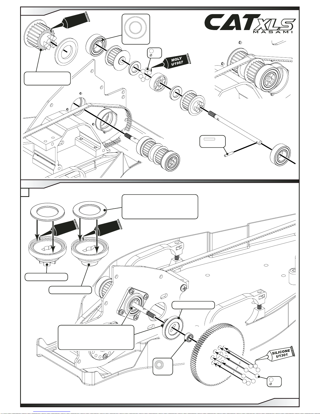
STEP 6
PAGE 6
STEP 7
A
ø1.5 X 7.8
x 1
IMPORTANT
Ensure the disk spring
is assembled as shown.
R/H washer carrier.
Disc Spring
x 1
M3 Nyloc
Steel
x 1
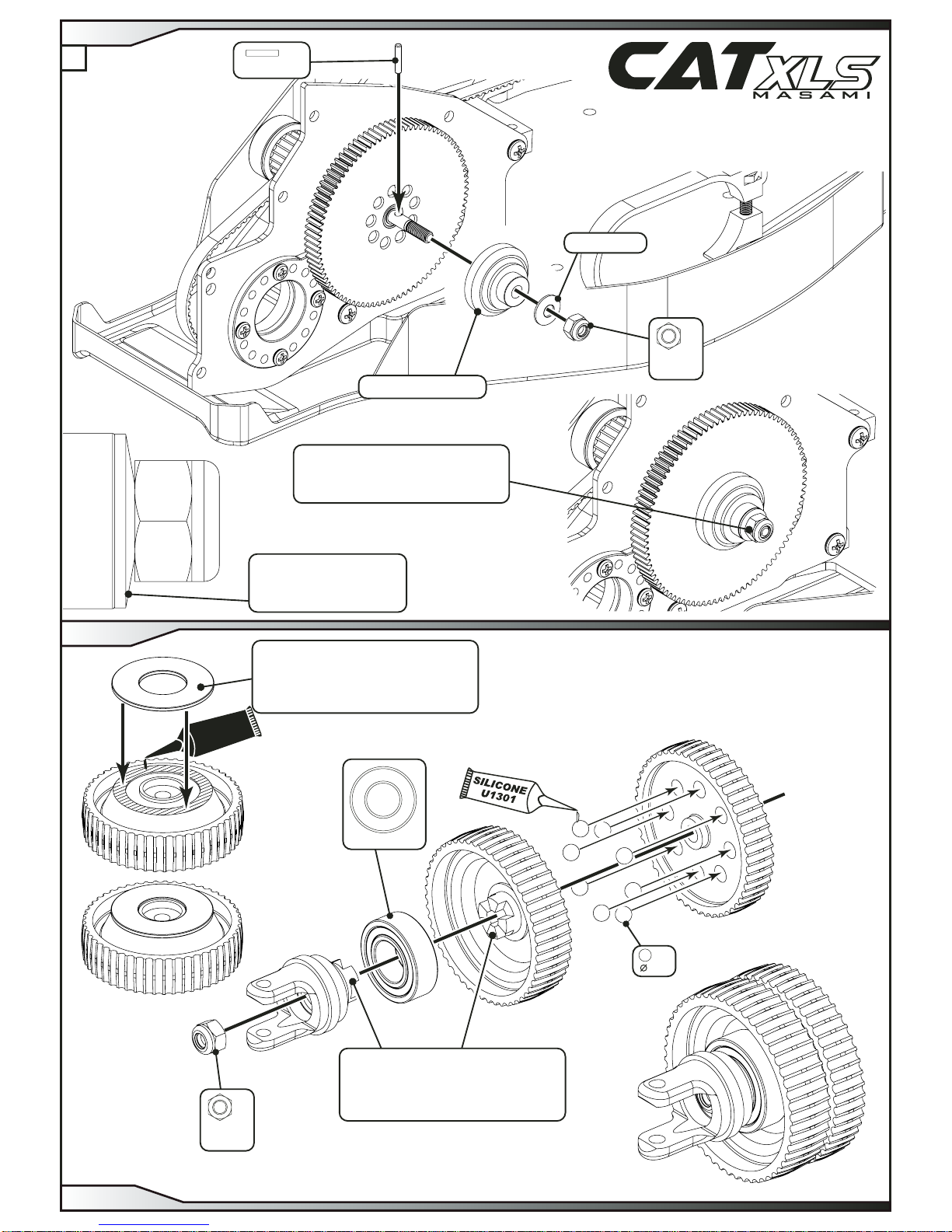
IMPORTANT
Tighten nut to flatten the disk spring
then undo 1/4 turn.
IMPORTANT
Ensure the washer is fully
degreased before applying super glue.
(Two part epoxy may also be used)
8 x 16 x 5
x 1
3.00
x 8
IMPORTANT
Ensure the drive dogs engage
correctly and push the parts
together firmly.
Super Glue
H1057
M3 Nyloc
Steel
x 1
STEP 7
PAGE 7
STEP 8
B
IMPORTANT
Ensure the washer is fully
degreased before applying super glue.
(Two part epoxy may also be used)
Super Glue
H1057
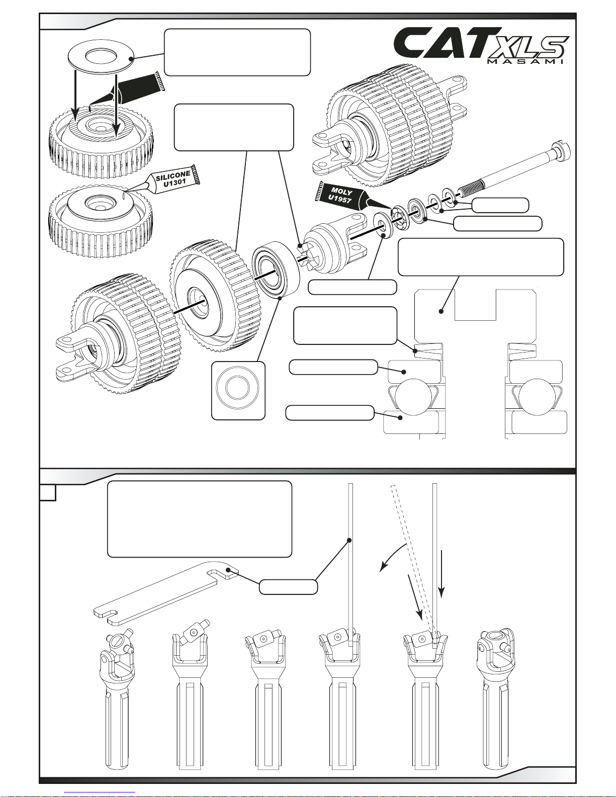
INTEGRATOR DEFINITION.
The Integrator combines the two outputs from the spur gear differential into a single drive to the front belt
and drive to the rear wheels.
IMPORTANT
Ensure the disc springs
are assembled as shown.
IMPORTANT INTEGRATOR SETTING
Tighten screw to flatten the disk
springs then undo 1/4 turn.
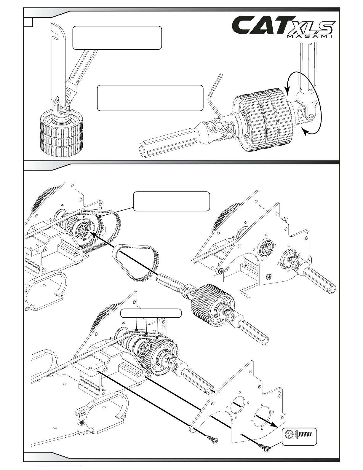
IMPORTANT
The sequence of drawings below shows
the assembly procedure of all universal joints,
driveshafts, axles and diff outputs.
NOTE
Warming the plastic parts
will help make the assembly easier.
U.J Spanner
8 x 16 x 5
x 1
IMPORTANT
Ensure the drive dogs engage
correctly and push the parts
together firmly.
Small grooved washer
Big grooved washer
Small grooved washer
Big grooved washer
Disc springs
1
2
3
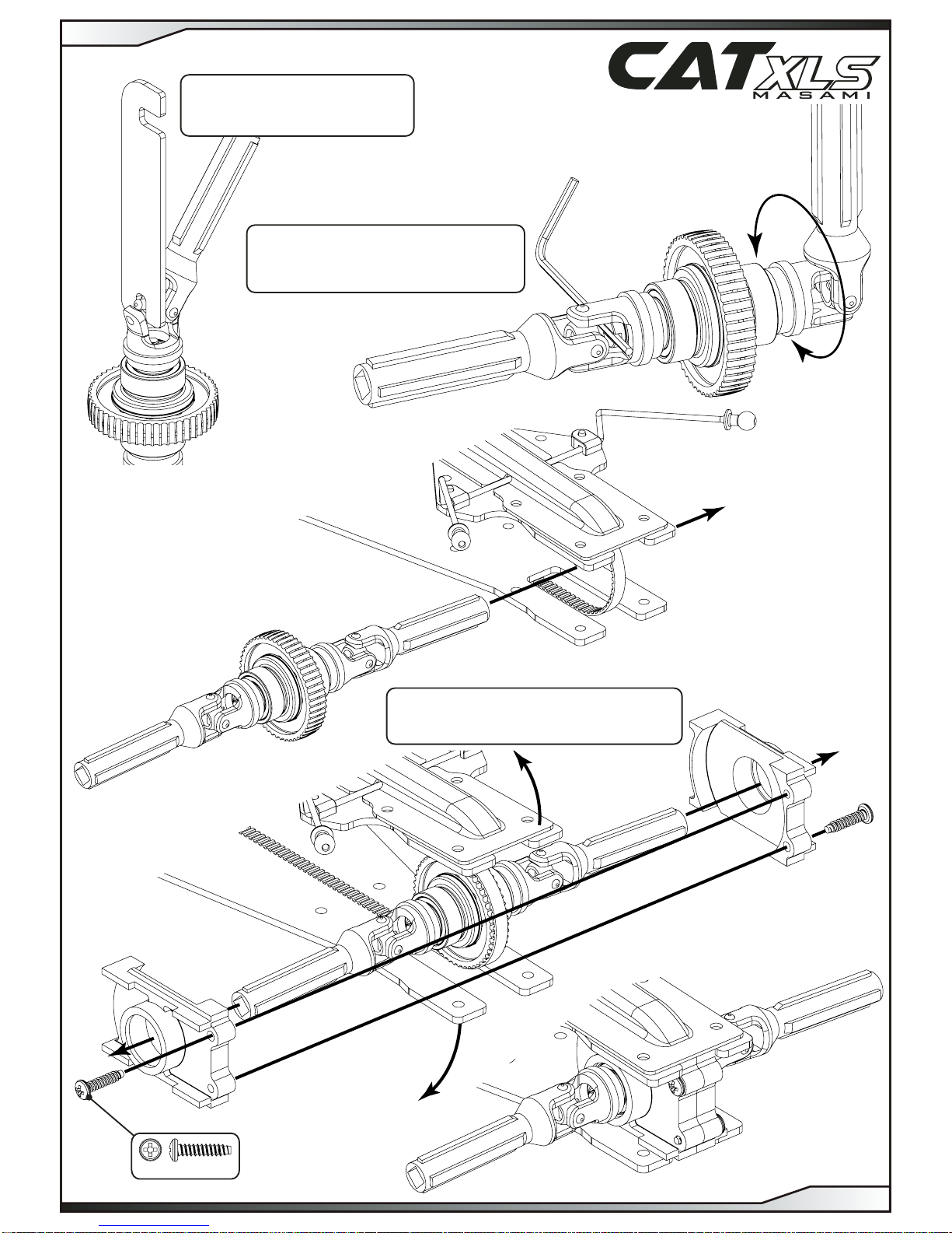
STEP 9
PAGE 8
STEP 10
A
IMPORTANT
Use the same assembly procedure
as shown on page 8 STEP 10 A.
IMPORTANT
To adjust the integrator setting when assembled
place an allen key into the screw head slot
and turn the output on the opposite side.
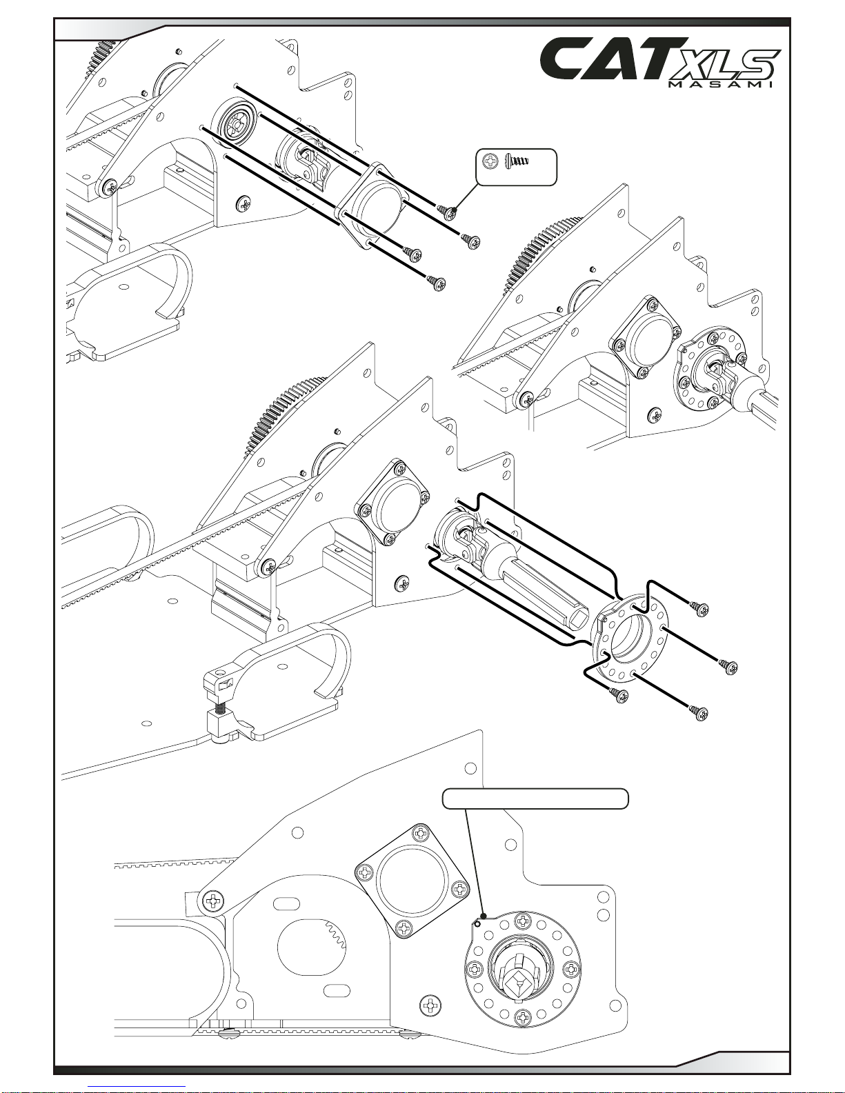
No4 x 3/8”
x 2
Assemble belts as shown.
Assemble the right hand rear belt
first, then the Integrator
and then the left hand rear belt.
THE UNDERTRAY HAS BEEN HIDDEN FOR ILLUSTRATION PURPOSES ONLY.
(DO NOT REMOVE THE UNDERTRAY)
STEP 10
PAGE 9
STEP 11
B
Set the eccentric as shown for now.
No2 x 3/16” x 8
STEP 12
PAGE 10
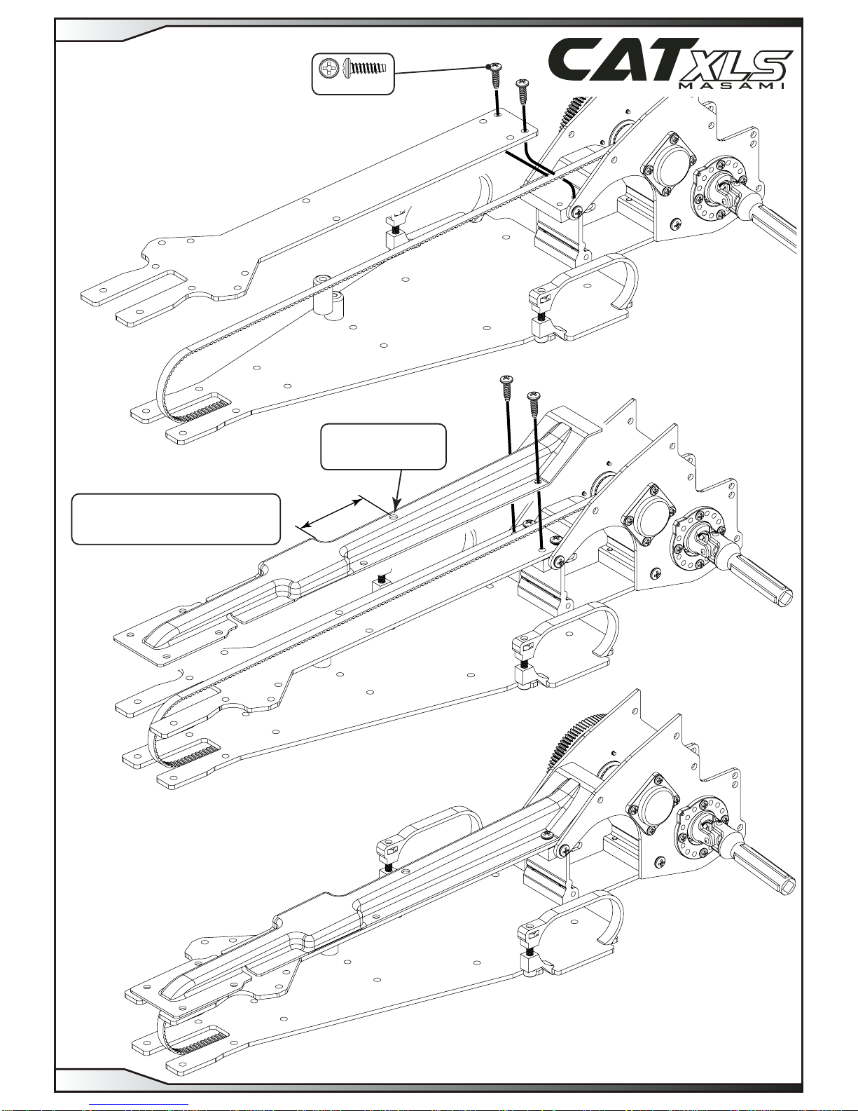
34.00 mm
No4 x 3/8” x 4
Optional ø3.00 hole
for checking the front
belt tension.
Cut out the belt cover as
shown before assembly.
STEP 13
PAGE 11
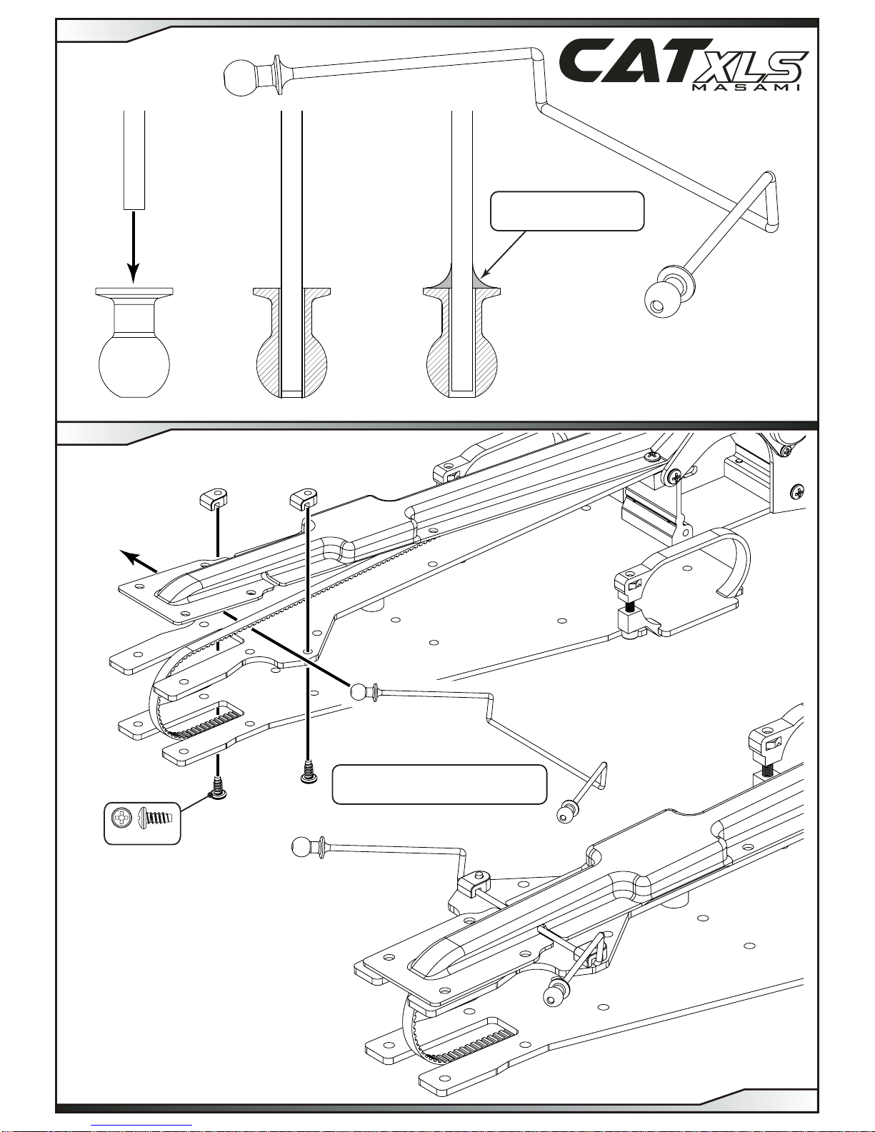
Solder the anti-roll bar to
the roll bar balls as shown.
IMPORTANT
The roll bar must go under the belt.
x 2
No4 x 1/4”
STEP 14
PAGE 12
STEP 15
IMPORTANT
Ensure the washer is fully
degreased before applying super glue.
(Two part epoxy may also be used)
8 x 16 x 5
x 1
3.00
x 8
IMPORTANT
Ensure the drive dogs engage
correctly and push the parts
together firmly.
Super Glue
H1057
M3 Nyloc
Steel
x 1
IMPORTANT
Ensure the washer is fully
degreased before applying super glue.
(Two part epoxy may also be used)
Super Glue
H1057
IMPORTANT
Ensure the disc springs
are assembled as shown.
IMPORTANT FRONT DIFF SETTING
Tighten screw to flatten the disk
springs then undo 1/4 turn.
8 x 16 x 5
x 1
IMPORTANT
Ensure the drive dogs engage
correctly and push the parts
together firmly.
Small grooved washer
Big grooved washer
Small grooved washer
Big grooved washer
Disc springs
STEP 16
PAGE 13
STEP 17
IMPORTANT
Use the same assembly procedure
as shown on page 8 STEP 10 A.
IMPORTANT
To adjust the front differential when assembled,
place an allen key into the screw head slot
and turn the output on the opposite side.
IMPORTANT
Bend the chassis and topdeck
to allow the transmission housings to slot into place.
No4 x 1/2” x 2
STEP 18
PAGE 14
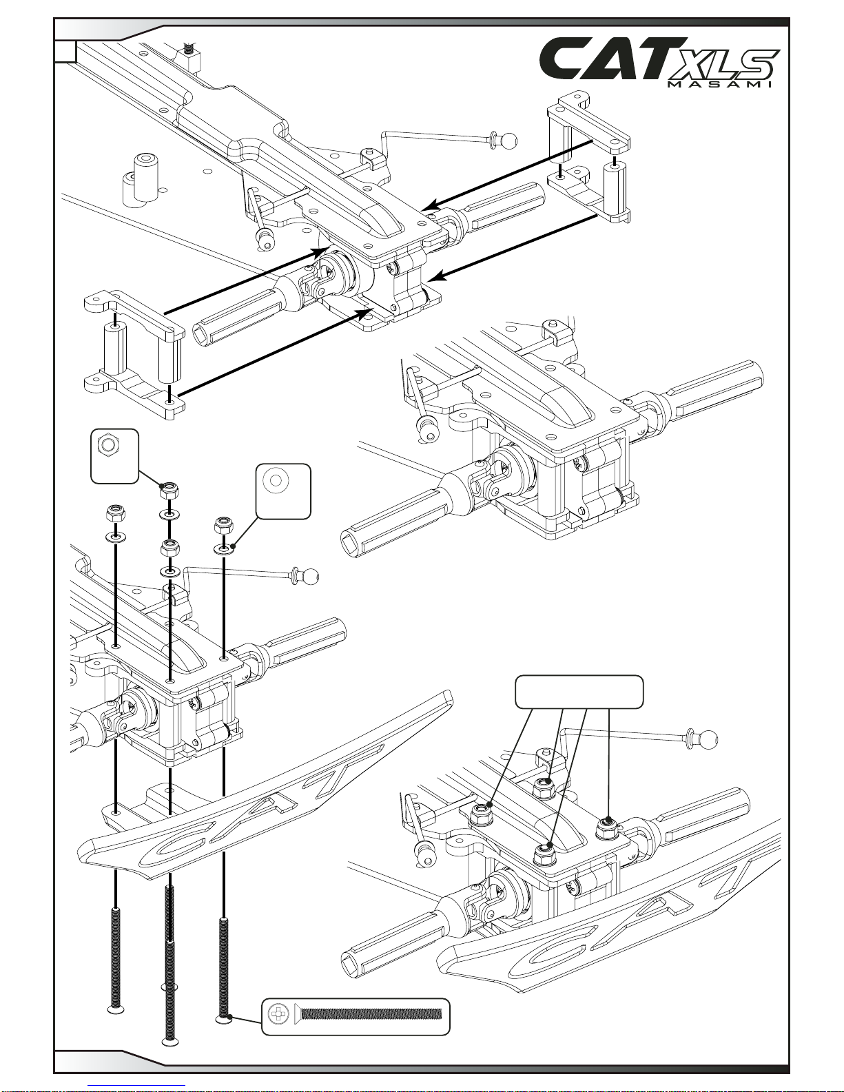
M3 x 40
x 4
M3
Washer
x 4
M3 Nyloc
Steel
x 4
IMPORTANT
Leave loose for now.
STEP 19
PAGE 15
A
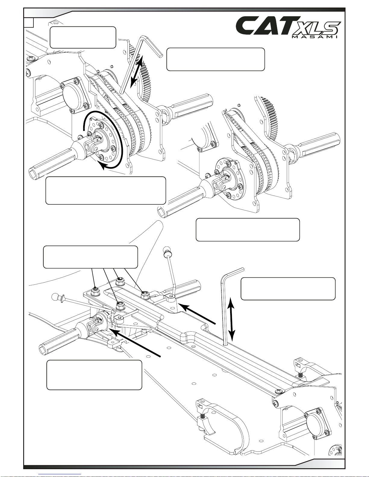
Rear Belt Adjustment
Check the rear belt tensions
by pushing on the belts with an allen key.
Rear Belt Adjustment
The eccentrics are already assembled in their loosest
position, rotate as shown to tighten the belt.
ensure both sides are set the same.
Front Belt
Check the front belt tension
by pushing on the belt with an allen key.
Front Belt Adjustment
Pull the front transmission housing
forwards to tighten the front belt tension.
Push it backwards to loosen the belt.
Front Belt
Tighten the nuts fully after the
required front belt tension is acheived.
NOTE
Side frame cut away
for illustration purposes only.
IMPORTANT
Always set the rear belt
tension before the front belt tension
STEP 19
PAGE 16
B