

Page 1
Doc. No. 10000436501_01_de / 02.2016
Aluminium systems
Schüco DCS Touch Display
Commissioning instructions
en
Page 2

4
Schücode Commissioning instructions – Schüco DCS Touch Display
en
00 Commissioning instructions
Dok-Nr.10000432116_01
Page 3

Commissioning instructions – Schüco DCS Touch Display 5
Contents
8 1. Notes on this document
8 1.1. Target groups and qualications
8 1.2. Handover of the document
8 1.3. Retention of the document
9 2. Security
9 2.1. About the safety instructions
9 2.2. Laws, regulations and technical rules
10 2.3. Proper use
11 2.4. General safety instructions
12 3. Contents of delivery, transportation and storage
12 3.1. Contents of delivery for Schüco DCS Touch Display
12 3.2. Contents of delivery for Schüco IP secure connector
12 3.3. Transportation and storage
Schüco de
13 4. Technical data
13 4.1. Schüco DCS Touch Display
15 4.2. Schüco IP secure connector
16 5. System overview
16 5.1. Overview of system components
17 6. IP secure connector
18 6.1. Overview of IP secure connector
20 6.2. Connections for Schüco IP secure connector
22 6.2.1. Conguration of „OUT2“ on IP secure connector
23 7. DCS Touch Display
24 7.1. Overview of DCS Touch Display
25 7.2. Connections to Schüco DCS Touch Display
26 7.2.1. Connection to lock technology
26 7.2.2. Dismantling
29 8. Screen surface
30 8.1. Start screen
31 8.2. Doorbell list
33 8.2.1. Making a call
34 8.2.2. Ending a call
34 8.3. Entering the access code
37 8.4. Conguration
38 8.4.1. Error messages
39 8.4.2. Network
41 8.4.3. Audio
42 8.4.4. Screen
43 8.4.5. Alarm
44 8.4.6. Language
45 8.4.7. Test
48 8.4.8. Cleaning the display
48 8.4.9. IP secure connector
50 8.4.10. Remote maintenance
51 8.4.11. Close conguration
52 8.5. Aktion auswählen
53 8.6. Symbols
Dok-Nr.10000432116_01
Page 4

6
Schücode Commissioning instructions – Schüco DCS Touch Display
54 9. Web interface
55 9.1. Accessibility
55 9.2. Calling up the web interface
57 9.3. Logging in
58 9.4. Conguration
59 9.5. Message boxes
60 9.6. Overview when logged in
62 9.7. Network
64 9.8. SIP
64 9.8.1. SIP settings
65 9.8.2. SIP server
66 9.8.3. SIP connection
67 9.9. Device
67 9.9.1. Device
73 9.9.2. Audio
74 9.9.3. Video
76 9.9.4. Motion detection
78 9.9.5. Buttons
95 9.10. Activity
96 9.10.1. Activities
96 9.10.2. Adding an activity card
97 9.10.3. Editing an activity
98 9.10.4. Creating an activity
102 9.10.5. Precongured activities.
103 9.11. Action sequences
104 9.11.1. Action sequences
104 9.11.2. Editing action sequences
106 9.11.3. Actions
108 9.11.4. Creating an action sequence
109 9.11.5. Anti-theft sequence
114 9.11.6. Precongured action sequences
117 9.12. Contacts
118 9.12.1. Editing a contact
119 9.12.2. Adding a contact
121 9.12.3. Exporting contacts
122 9.12.4. Kontakte importieren
125 9.12.5. Editing a precongured contact
129 9.12.6. Peer-to-Peer
130 9.12.7. Hidden contact
133 9.13. Media
134 9.13.1. Adding an audio le
136 9.13.2. Photos
137 9.14. System
138 9.14.1. System
138 9.14.2. Conguration
139 9.14.3. E-mail settings
139 9.14.4. Exporting the conguration
139 9.14.5. Importing the conguration
143 9.15. User administration
143 9.15.1. Users
144 9.15.2. Prole
146 9.15.3. Roles
147 9.15.4. Editing a role
150 9.15.5. Creating a user
152 9.15.6. Creating a role
155 9.15.7. Changing a password
158 9.15.8. Changing the access code
160 9.16. Codecs
Dok-Nr.10000432116_01
Page 5

161 9.17. Remote maintenance
162 10. Replacing an IP secure connector
163 11. Faults and troubleshooting
163 12. Care and maintenance
163 13. Decommissioning
164 14. Service and support
Commissioning instructions – Schüco DCS Touch Display 7
Schüco de
Dok-Nr.10000432116_01
Page 6

8
Schücode Commissioning instructions – Schüco DCS Touch Display
1. Notes on this document
1.1. Target groups and qualications
This document is intended for qualied personnel, such as trained tters and electricians.
Before installing and commissioning, read through this document thoroughly and adhere to the
specied sequence of the instructions. Schüco International KG shall not be liable for any damage
which arises from a failure to adhere to these instructions.
Qualied personnel are people who know how to assemble, install, commission, test and operate the
product and who have the relevant qualications, e.g. who have been trained and instructed in
accordance with safety regulations on the maintenance and use of appropriate safety equipment and
who have received training in First Aid.
Experts are people whose training and experience means that they have sufcient knowledge of
power-operated windows, doors and gates and the corresponding electrical installations.
They are familiar with the relevant accident prevention regulations, government Health & Safety
regulations, guidelines and generally recognised technical regulations so that they are qualied to
judge the occupational safety of power-operated windows, doors and gates and the corresponding
electrical installations.
1.2. Handover of the document
After commissioning, hand over all the documentation pertaining to this product to the end customer.
Make them aware of the safety instructions, to which they must pay particular attention.
1.3. Retention of the document
This document is a component of the product. Keep this document in an accessible place even after
installation and commissioning, so that the information is always available.
Dok-Nr.10000432116_01
Page 7
Commissioning instructions – Schüco DCS Touch Display 9
2. Security
2.1. About the safety instructions
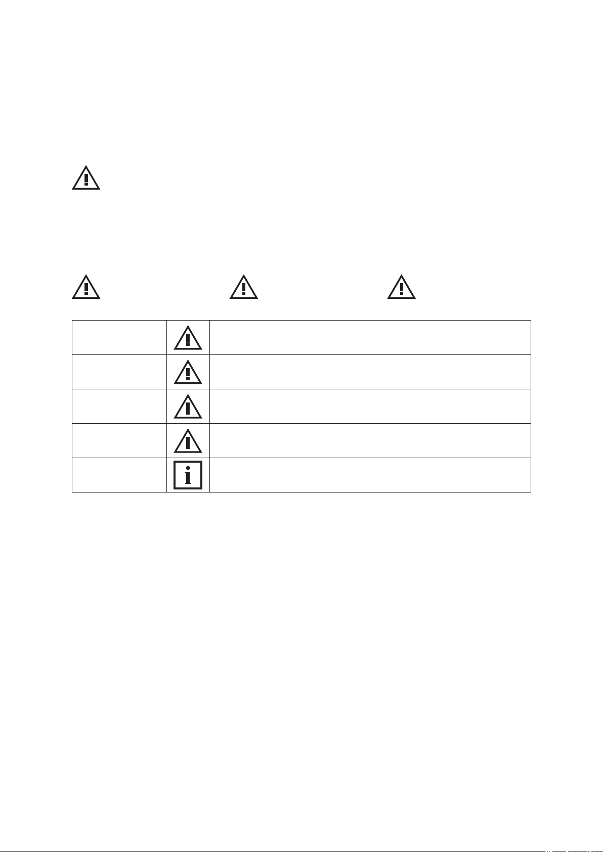
KEY WORD
Type / source / consequence of the danger
Pictograms and key words advise of the type of danger and the level of danger:
Schüco de
General
personal injury
DANGER
WARNING
CAUTION
NOTE
INFORMATION
Imminent danger resulting in death or severe injuries.
Potential imminent danger which may lead to death or severe injuries.
Potentially dangerous situation which may lead to minor injuries.
Imminent danger of damage to property which may lead to damage to
or destruction of the product or environment.
Information
Information, tips and advice
Personal injury from
electrocution
Damage to property.
2.2. Laws, regulations and technical rules
During installation and operation, observe the international, national and local safety regulations, laws
and guidelines.
Accepted practice as usually codied in standards, guidelines, specications and regulations laid
down by recognised bodies must be followed.
This applies in particular to:
● European and international standards, e.g. EN 60335-2-103 on the safety of electrical devices
● VDE guidelines and regulations, e.g. DIN VDE 0100, DIN VDE 0160, DIN VDE 0632
● Guidelines and regulations of the professional trade associations, e.g. BGR 232 (previously ZH
1/494) for power-operated windows, doors and gates, BGV A2 (previously VBG4) accident prevention regulations for electrically-operated systems and devices
● Data sheets of the German Association of Window and Façade Manufacturers e.V.
(e.g. KB.01 / KB.02 electrically operated windows)
Dok-Nr.10000432116_01
Page 8

10
Schücode Commissioning instructions – Schüco DCS Touch Display
2.3. Proper use
The DCS Touch Display is a modular intercom station that is based on SIP technology
(RFC 2327, RFC 2396, RFC 2617, RFC 2833, RFC 2876, RFC 3261, RFC 3310 and RFC 3550).
It is intended for door communication inside and outside as well as for access control.
The DCS Touch Display must be ush-tted, whereby it is integrated into the existing DCS prole,
for example, or alternatively installed on a panel or a wall. In addition to the 4.3 inch colour
touchscreen, it has a camera with motion detection, two voice-optimised microphones and a protected
loudspeaker. Thanks to state-of-the-art technology, the DCS Touch Display uses very little energy,
despite its wide range of functions. It can be combined with a Schüco DCS motion detector,
Schüco DCS LED spotlight and DCS proximity switch, for example. Proper use also includes adhering
to the installation and commissioning instructions. Any alternative use or a use beyond this remit is not
in accordance with its purpose. Incorrect use or unauthorised modication of the product may result in
death or serious injury, or damage to the product and other material assets.
The manufacturer / supplier shall not be liable for any resulting damage. The user alone bears the
risk. Only original replacement parts may be used.
Children should be supervised to ensure that they do not play with the device. .
Dok-Nr.10000432116_01
Page 9

Commissioning instructions – Schüco DCS Touch Display 11
Schüco de
2.4. General safety instructions
Follow the safety instructions in this document so as not to endanger your own life or that of others
and to ensure error-free operation.
DANGER
Imminent danger resulting in death or severe injuries.
► Before any work is carried out on the product, all power packs must be disconnected and
protected against anyone inadvertently switching them back on.
► Following each installation or alteration to the electrical system, carry out a test run to test all
functions.
► When operating, note that Schüco windows and doors may open and close automatically when
left unattended.
For reasons of simplicity, this documentation does not contain every detail of all product types and it
cannot cover every possible installation, operation or maintenance scenario.
Should you require further information or encounter problems not dealt with in detail in these
installation instructions, contact technical support +49 (0) 521 783 – 665. Moreover, we would like
to point out that these installation instructions do not form part of or replace any previous or existing
agreement or contract.
All obligations to be fullled by Schüco can be found in the appropriate sales contract, which also
contains the complete current conditions of the warranty. These installation instructions do not add to
or limit the contractual warranty conditions. .
Dok-Nr.10000432116_01
Page 10

12
Schücode Commissioning instructions – Schüco DCS Touch Display
3. Contents of delivery, transportation and storage
3.1. Contents of delivery for Schüco DCS Touch Display
Open all the packing units. Check that no components are missing and familiarise yourself with
the components.
Supplied with the Schüco DCS Touch Display are the following:
Art. No. Description
263 267 Schüco DCS Touch Display
263 272 DCS Touch Display installation tool
Installation instructions (German/English)
3.2. Contents of delivery for Schüco IP secure connector
Open all the packing units. Check that no components are missing and familiarise yourself with the
components.
Supplied with the IP secure connector are the following:
Art. No. Description
263 268 Schüco IP secure connector
6 Plug-in connectors
4 Fixing screws (including two spare screws)
2 Cable ties for the mains lead cleat
3.3. Transportation and storage
NOTE
Damage to property.
► Protect against impact.
► Store only in dry interior rooms.
► Protect the device against moisture and dirt.
Dok-Nr.10000432116_01
Page 11
4. Technical data
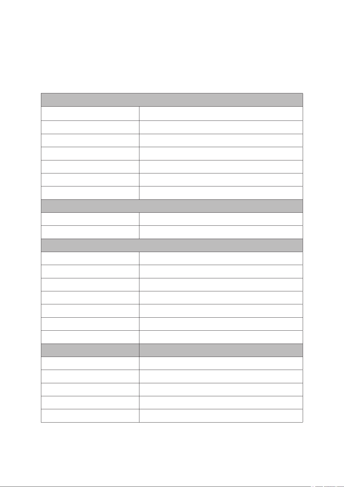
4.1. Schüco DCS Touch Display
General data
Commissioning instructions – Schüco DCS Touch Display 13
Schüco de
Installation type
Integrated in the prole in the DCS unit, leaf and outer frame,
wall mounting and panel mounting
Material Aluminium, PVC-U, toughened safety glass
Colour Black
Weight 0,702 kg
Power supply PoE+ IEE802.3at/Typ2 min 44 V
Alternative power supply IEE802.3at
Input current (max.) 0,5 A
Call, speak, listen functions
Audio coding G.722 , G.711 a-law, G.711 u-law
Video coding H.264
Device data: Screen
Screen TFT active matrix, fully bonded
Size 4,3“
Resolution 480 x 800 Pixel
Screen brightness Min. 450 cd/m², typically 600 cd/m², automatic
Angle of vision 80° in all directions
Colour depth 24 bit (true color)
Contrast ratio 1000 (typical); 700 (minimum)
Device data: Camera
Camera opening angle 120° horizontally, 60° vertically
Video resolution 1280 x 960 (1.2 MP)
Front glass TSG
Light sensitivity Lens: f/2.0
Capability in backlit situations HDR-based compensation
Dok-Nr.10000432116_01
Page 12

14
Schücode Commissioning instructions – Schüco DCS Touch Display
Access control
Code lock 4 or 6-digit code entry
System features
Peer-to-Peer operation Yes
Ports Line out, line in, 2 x USB, Ethernet
Inputs 1 input
Outputs 1 potential-free output, can be freely congured
Commissioning and maintenance properties
Conguration
Basic settings on the DCS Touch Display, further settings
via the web interface
Dimensions
Housing 212 x 70 x 46 mm (H x W x D)
Climatic properties
Permissible ambient temperature -20 °C to +70 °C
Protection rating IP 54 (when installed)
Guidelines
Conforms to RoHS, tested in accordance with
IEC/EN 60950-1
Dok-Nr.10000432116_01
Page 13
Commissioning instructions – Schüco DCS Touch Display 15
4.2. Schüco IP secure connector
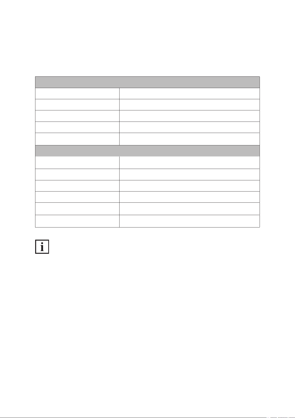
General
Dimensions 262 x 59 x 26 mm (H x W x D)
Protection rating IP 20
Temperature range +5°C to +45°C
Air humidity 5% to 93%, non-condensing
Schüco de
Installation
Integrated in the DCS door prole or by the customer on the
inside of the building
Key electrical data
Power supply
12 - 30 V DC (+/-15 %) stabilised ,
von SELV/LPS (max 100 W) Spannungsquelle
Operating voltage Recommended: 24 V DC, stabilised
DC OUT 3 With potential, 12-30 V DC, max. 1.5 A
OUT 1 / OUT 2 Potential-free
Contact loading of outputs OUT 1
and OUT 2
Guidelines
6-24 V AC/DC + - 15 %, max. 2 A
von SELV/LPS (max 100 W) -Stromkreis
Conforms to CE and RoHS,
IEC/EN 60950-1
INFORMATION
SELV electrical circuit
The relay output must only be used for SELV electrical circuits. A SELV electrical circuit in accordance
with IEC/EN 60950-1 must be securely isolated (e.g. by means of double insulation) from
a dangerous electrical circuit (e.g. 230 V or 110 V mains supply circuit) and must not exceed the
voltage value of 60 V DC or 42.4 V ACpeak (30 V ACeff).
IP secure connector circuit breakers
All inputs and outputs of the IP secure connector are protected against voltages up to 60 V DC and
42 V AC. The „DC-OUT 3“ output also has circuit breakers to protect against external supply, short
circuiting and reverse polarity.
You can nd examples of connecting LED spotlights and/or motion detectors in Chapter 10,
„Connection examples“, in the installation instructions. .
Dok-Nr.10000432116_01
Page 14
16
Schücode Commissioning instructions – Schüco DCS Touch Display
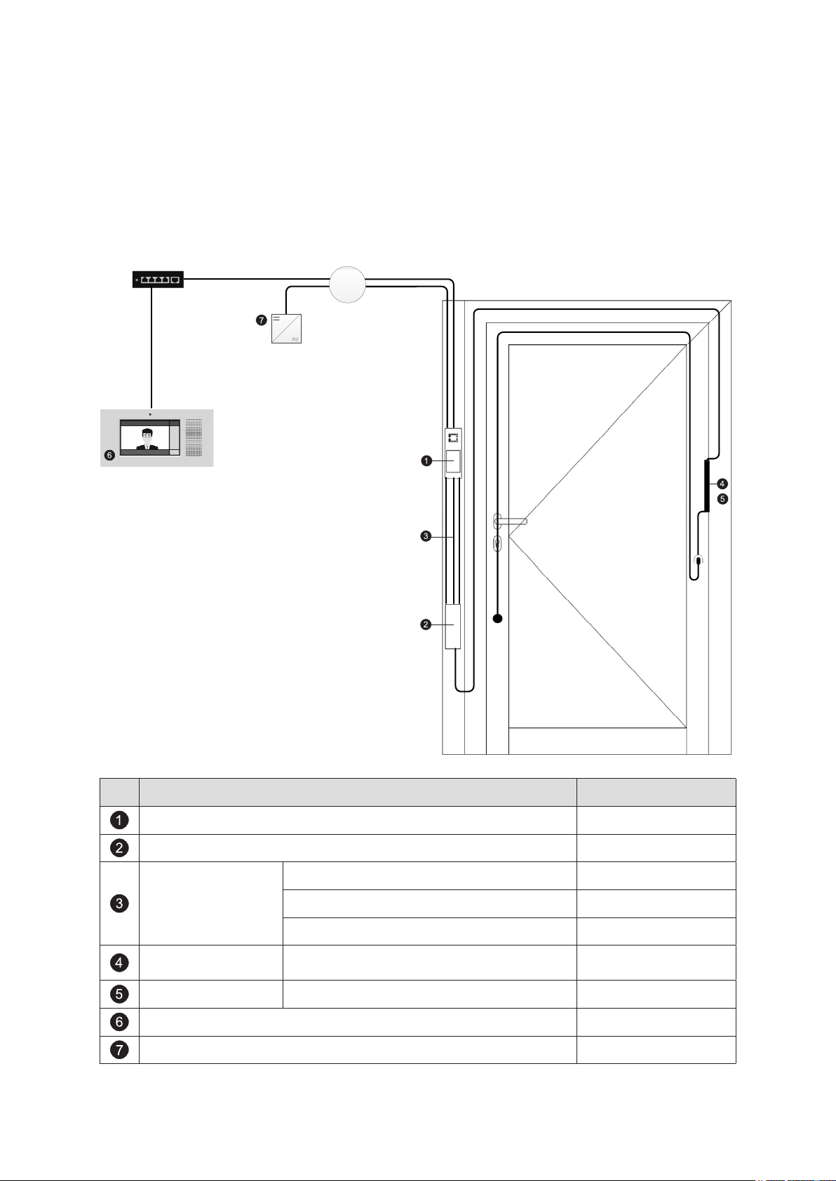
5. System overview
5.1. Overview of system components
Switch / router
Junction box
Pos. Description Art. No.
DCS Touch Display 263 267
IP secure connector 263 268
Outer frame installation 263 278
Cable kits
Leaf frame installation 263 277
DCS in secondary leaf (double-leaf door) 263 279
Cable link connector Can be split
263 016
263 017
Cable link connector Network 263 273
Touch Display indoor intercom station* 263 283
Top hat rail power pack 24 V DC, 2 A 263 099
* or an alternative indoor intercom station in accordance with the compatibility list
(see www.schueco.de/dcs-touchdisplay)
Dok-Nr.10000432116_01
Page 15

Commissioning instructions – Schüco DCS Touch Display 17
Schüco de
6. IP secure connector
INFORMATION
The DCS Touch Display can also be operated without the IP secure connector. Note that a suitable
PoE+ switch must be provided by the customer in this case. If no IP secure connector is provided
for the installation, you can skip this chapter.
The IP secure connector (Art. No. 263 268) is an optional device for greater output and safety.
It protects the household electricity supply from unauthorised external manipulation attempts.
In cases of unauthorised removal, the DCS Touch Display disconnects from the network.
The IP secure connector also guarantees secure control of electric strikes and electric locks.
It is recommended that you use the IP secure connector on all external doors.
INFORMATION
The IP secure connector must be installed on the inside of the building. .
For perfect operation of the IP secure connector, connection to the Schüco DCS Touch Display
is required. .
Dok-Nr.10000432116_01
Page 16

18
59
27
262
Schücode Commissioning instructions – Schüco DCS Touch Display
6.1. Overview of IP secure connector
Front view Rear view
-
+
12-30VDC
COM
NO/NC
+ -
DC-
DC+
DC-OUT1
max. 1,5A
12-30VDC
COM
OUT2
NO
6-24V
AC/DC
max. 2A
-
IN2
+
22mA
12-30VDC
SUPPLY
max. 4A
OUT1
IN1
Side view
FRONT VIEW
alle Maße in mm
Using the „OUT2“ switch, you can select whether the „OUT2“ relay is to function as a closer
(NO/Normally Open) or as an opener (NC/Normally Closed).
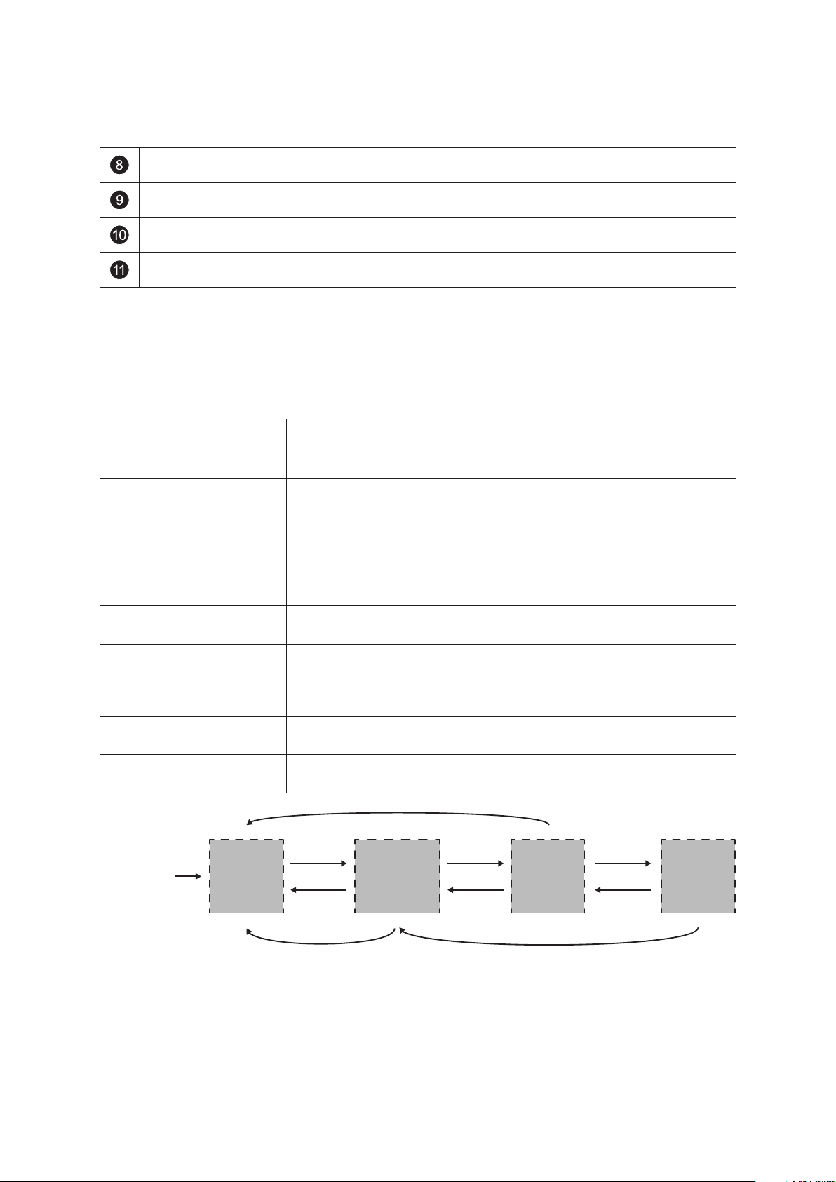
The „STATUS“ LED indicates the status of the IP secure connector (see the following table).
By pressing the „PAIRING“ button, the IP secure connector can be paired with a
DCS Touch Display.
The „PSE OK“ LED indicates the PoE status. If it is permanently lit, then there is a PoE+
power supply at the „DISPLAY“ RJ45 socket.
The „INK/ACT“ LED indicates whether data is being transmitted between the „DISPLAY“ RJ45
socket and the building’s internal switch.
The „100M“ LED indicates whether a transmission speed of 100 Mbps has been achieved
between the IP secure connector and the DCS Touch Display at the „DISPLAY“ RJ45 socket.
The „INK/ACT“ LED indicates whether data is being transmitted between the „LAN“ RJ45
socket and the building’s internal switch.
Dok-Nr.10000432116_01
Page 17
Commissioning instructions – Schüco DCS Touch Display 19
Schüco de
The „100M“ LED indicates whether a transmission speed of 100 Mbps has been achieved
between the IP secure connector and the building’s internal switch at the „LAN“ RJ45 socket.
The IP secure connector is connected to the DCS Touch Display via the „DISPLAY“
connection.
The IP secure connector is connected to the building‘s internal switch/router via the
„LAN“ connection.
The IP secure connector is supplied with power by means of the connections on the reverse
side. In addition, further devices can be connected via two inputs and three outputs.
The „STATUS“ LED indicates the operating status of the IP secure connector.
See the following table for the meaning of the signals:
Display Meaning
Permanently lit In the paired mode, the IP secure connector is assigned to a
DCS Touch Display. No error has been detected.
Flashes slowly In the unpaired mode, the IP secure connector has not been assi-
gned to a DCS Touch Display. Even after the „PAIRING“ button has
been pressed, the „STATUS“ LED ashes slowly until the IP secure
connector has been assigned to a DCS Touch Display.
Flashes quickly In the alarm mode, the connection of the IP secure connector to the
building‘s network is broken and the PoE+ power supply to the
DCS Touch Display is disconnected (factory default).
Flashes slowly twice In the maintenance mode, the alarm is deactivated for 15 minutes
so that the DCS Touch Display can be removed.
Flashes quickly three times In the so-called weak alarm mode, the IP secure connector is
connected to a DCS Touch Display, however there is no connection
to the building‘s network (e.g. when the network cable is unplugged or
in the event of power failure).
Flashes slowly twice and
quickly once
In the update mode, new rmware is loaded into the IP secure
connector.
Flashes in an SOS rhythm In the rescue mode, an error occurred during the rmware update.
A window appears in the browser.
Connection
DCS Touch Display to
IP Secure Connector
Dok-Nr.10000432116_01
Alarm Mode
RJ45 sockets
IP Secure Connector
LAN: inactive
DISPLAY: inactive
button “PAIRING”
pressed
5 min time window
has elapsed
restart
DCS Touch Display
Alarm Mode activated
via Theft Alarm (30 s delayed)
Disconnected
Mode
RJ45 sockets
IP Secure Connector
LAN: 5 min active
DISPLAY: 5 min active
successfully
connected
button “PAIRING”
pressed
Connected
Mode
RJ45 sockets
IP Secure Connector
LAN: active
DISPLAY: active
button “PAIRING”
pressed
DCS Touch Display
cannot be reached
(e.g. when restarting)
DCS Touch Display
can be reached again
Light
Alarm Mode
RJ45 sockets
IP Secure Connector
LAN: inactive
DISPLAY: active
Page 18
20
Schücode Commissioning instructions – Schüco DCS Touch Display
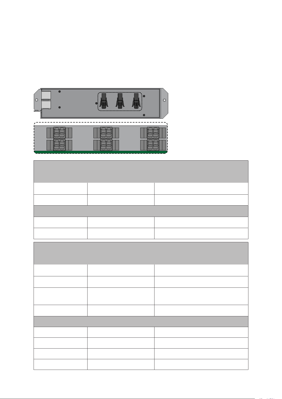
6.2. Connections for Schüco IP secure connector
The connections are located on the rear of the IP secure connector. The corresponding connectors
are supplied with the product or are included in the cable kits.
The inputs and outputs on the rear of the IP secure connector are assigned as follows:
IN2
IN1
+
+
–
–
OUT2
OUT1
NO/
NC
NO COM
COM
DC-OUT3
SUPPLY
+
+
–
–
Voltage range Notes
Power supply
SUPPLY+ 12–30 VDC (max. 4 A)
Max. 30 V DC Recommended power pack
Art. No. 263 099 24 V 2 A
SUPPLY– GND
Output
DC-OUT3+ 12–30 VDC (max. 1,5 A) Contact with potential
DC-OUT3– GND
Voltage range Notes
Relay
OUT1 NO 6–24 VAC/VDC (max. 2 A)
Potential-free contact Normally open
(closer) max. 60 V DC
OUT1 COM
Potential-free contact Normally Open
OUT2 NO/NC 6–24 VAC/VDC (max. 2 A)
(closer) or Normally Closed (opener) can
be set via the „OUT2“ switch
OUT2 COM
Inputs
IN1+ 12–30 VDC (~ 22 mA) Galvanically isolated
IN1– GND
IN2+ 12–30 VDC (~ 22 mA) Galvanically isolated
IN2– GND
Dok-Nr.10000432116_01
Page 19

Commissioning instructions – Schüco DCS Touch Display 21
Schüco de
INFORMATION
SELV electrical circuit
The relay output must only be used for SELV electrical circuits. A SELV electrical circuit in accordance
with IEC/EN 60950-1 must be securely isolated (e.g. by means of double insulation) from a
dangerous electrical circuit (e.g. 230 V or 110 V mains supply circuit) and must not exceed the
voltage value of 60 V DC or 42.4 V ACpeak (30 V ACeff).
IP secure connector circuit breakers
All inputs and outputs of the IP secure connector are protected against voltages up to 60 V DC and
42 V AC. The „DC-OUT 3“ output also has circuit breakers to protect against external supply, short
circuiting and reverse polarity.
You can nd examples of connecting LED spotlights and/or motion detectors in Chapter 10,
„Connection examples“, in the installation instructions. .
Dok-Nr.10000432116_01
Page 20
22
Schücode Commissioning instructions – Schüco DCS Touch Display
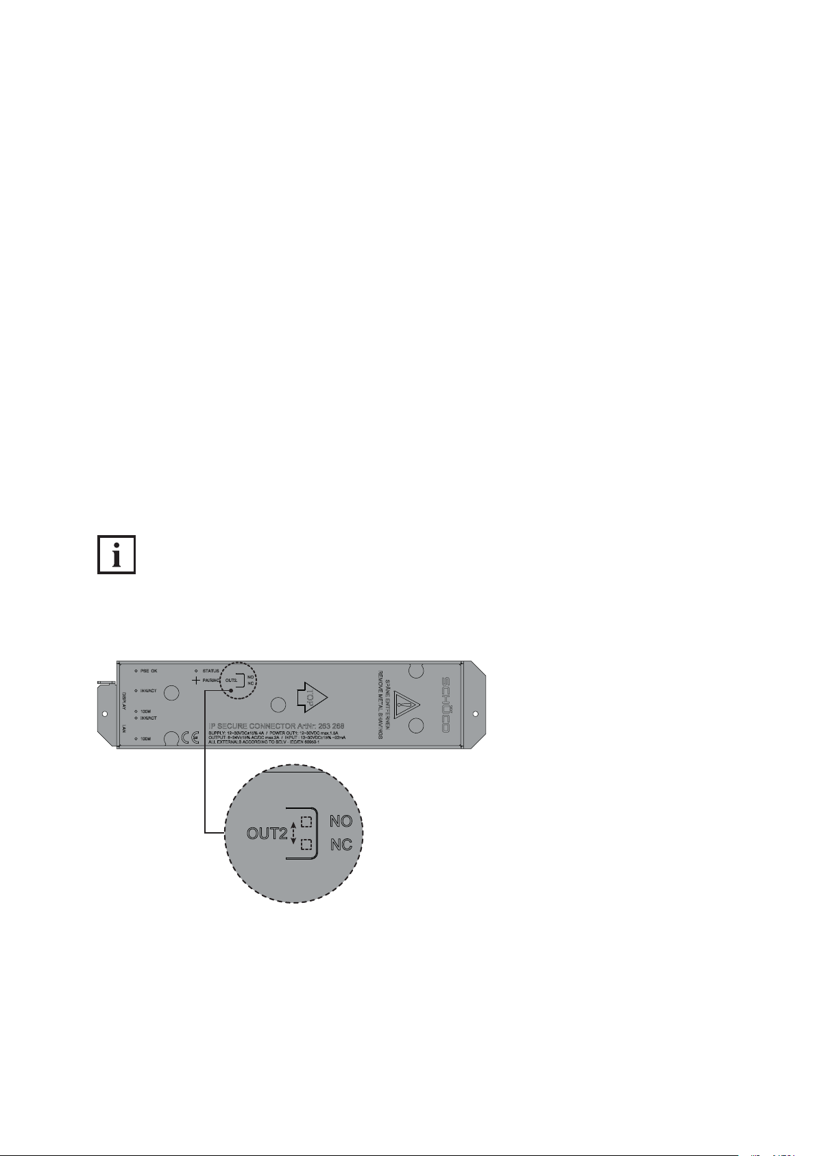
6.2.1. Conguration of „OUT2“ on IP secure connector
Using the „OUT2“ switch, you can select whether the „OUT2“ relay is to function as a closer (NO) or
as an opener (NC). Depending on the device connected, a closer can be used for an external lamp
and an opener for function monitoring, for example.
● Closer (NO/Normally Open): If the closer is actuated, it closes a broken electrical circuit
(factory setting).
● Opener (NC/Normally Closed): If the opener is actuated, it breaks an existing electrical circuit.
Proceed as follows to congure the „OUT2“ relay:
1. Using an object (e.g. screwdriver or pen), press down on the foil above the imprint „OUT2“ to ac-
cess the switch.
2. Move the switch to the „NO“ position so that the „OUT2“ relay functions as a closer, or to the
„NC“ position so that it functions as an opener.
INFORMATION
„NC“ switch position
In the „NC“ (opener) switch position, the „OUT2“ relay is an inverted closer. This means that this relay
is open when there is no supply voltage at the IP secure connector.
Dok-Nr.10000432116_01
Page 21

Commissioning instructions – Schüco DCS Touch Display 23
Schüco de
7. DCS Touch Display
The door communication and access control are supplied in this module which is operated via a
touch interface. Door communication takes place via the open and unmodied SIP standard in
accordance with RFC 3261. Between one and an almost unlimited number of users can be connected
to the system.
There is the option to display pictures of the users or company logos next to the names on the screen.
The access control is code-based. Via a simple user management system, access codes can be
activated depending on times of the day and days of the week.
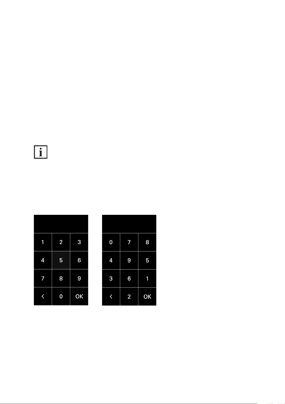
The digit buttons in the „code entry“ view can be displayed in a mixed, random order for increased
security. It is therefore no longer possible to reproduce the codes from ngerprint impressions.
Settings for door communication and access control are made via a clearly laid-out web interface.
Basic settings, such as the brightness of the screen, can be carried out directly on the
DCS Touch Display. The DCS Touch Display is equipped with inputs and outputs to which, for example, an electric strike for internal doors can be connected.
Data is communicated and power is supplied via a shared network cable.
Dok-Nr.10000432116_01
Page 22
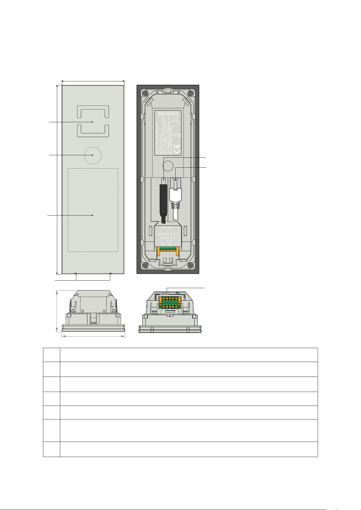
24
70
212
46
Schücode Commissioning instructions – Schüco DCS Touch Display
7.1. Overview of DCS Touch Display
A
B
E
F
C
D
G
70
A The loudspeaker openings are positioned such that the loudspeaker cannot be seen.
The high-resolution camera sits behind a tinted pane of glass, so that a person standing
B
directly in front of it cannot see that it is a camera.
The 4.3 inch colour Touch Display can automatically adjust its brightness
C
to suit the environment.
D The voice-optimised microphones are concealed.
E The two USB 2.0 ports turn the DCS Touch Display into a host for additional devices.
The RJ45 socket is used for the connection to the building‘s internal PoE+ switch or to the
F
IP secure connector, whereby the DCS Touch display is supplied with power in the form
of PoE+.
The inputs and outputs allow for additional devices to be directly connected to the
G
Schüco DCS Touch Display.
Dok-Nr.10000432116_01
Page 23

Commissioning instructions – Schüco DCS Touch Display 25
Schüco de
7.2. Connections to Schüco DCS Touch Display
On the underside there is a 2 x 5-pole socket with the inputs and outputs for
the Schüco DCS Touch Display. A suitable plug is supplied. The connections are assigned as follows:
A2A1 A3 A4 A5
B2B1 B3 B4 B5
Power supply Voltage range Notes
Input
A5 IN+ 12-30 V DC (22 mA) Galvanic separation, max. 60 V DC / 42 V AC
B5 IN- GND
Potential-free output
B3 OUT NO
6-24 V AC / V DC (max. 2
A)
Normally Open (closer),
max. 60 W power rating
B4 OUT COM
Output with potential
A4 OUT24V- GND
A3 OUT24V+ 24 V DC (max. 200 mA) Max. 4.8 W
Audio
A1 LINE-IN+ For microphones with line level
A2 LINE-IN-
B2 LINE-OUT-
B1 LINE-OUT+
Dok-Nr.10000432116_01
e.g. for AFIL (audio frequency induction loop.
This allows a hearing aid wearer to receive
interference-free audio signals by means
of the audio device)
Page 24
26
Schücode Commissioning instructions – Schüco DCS Touch Display
INFORMATION
DCS Touch Display power supply
A power supply in the form of PoE+ is required in order to operate the DCS Touch Display.
This is either provided by a suitable switch or by the IP secure connector. The maximum length of an
Ethernet cable between the DCS Touch Display and the switch or IP secure connector is 50 m.
DCS Touch Display circuit breakers
All inputs and outputs of the DCS Touch Display are protected against voltages above 60 V DC and
42 V AC. The „OUT24V“ output also has circuit breakers to protect against external supply,
short circuiting and reverse polarity.
SELV electrical circuit
The relay output must only be used for SELV electrical circuits. A SELV electrical circuit in accordance
with IEC/EN 60950-1 must be securely isolated (e.g. by means of double insulation) from a
dangerous electrical circuit (e.g. 230 V or 110 V mains supply circuit) and must not exceed the voltage value of 60 V DC or 42.4 V ACpeak (30 V ACeff).
7.2.1. Connection to lock technology
If no IP secure connector is used, proceed as follows to connect an electric lock to the DCS Touch
Display:
1. Connect the green control wires (ST) of the SafeMatic to the „A4“ socket („OUT COM“) and the
wires that supply power to the „A3“ socket („OUT NO“).
2. Ensure that the cables are laid correctly.
7.2.2. Dismantling
In order to be able to remove the Schüco DCS Touch Display, the alarm must be deactivated and the
unlocking mechanism released. The Schüco DCS Touch Display installation tool (Art. No. 263 272) is
required for the latter and is supplied with the Schüco DCS Touch Display.
INFORMATION
Removing the Schüco DCS Touch Display
It is essential that you observe the steps for deactivating the alarm prior to removal, as otherwise the
alarm mode will be activated. If the DCS Touch Display is connected to an IP secure connector in
the alarm mode, the connection between the DCS Touch Display and the building‘s network will be
disconnected when an attempt is made to remove the DCS Touch Display improperly. In this way, any
unauthorised access from outside via this network cable is successfully prevented.
To unlock the DCS Touch Display, proceed as follows, provided that it has already been
commissioned or connected to an IP secure connector:
Dok-Nr.10000432116_01
Page 25
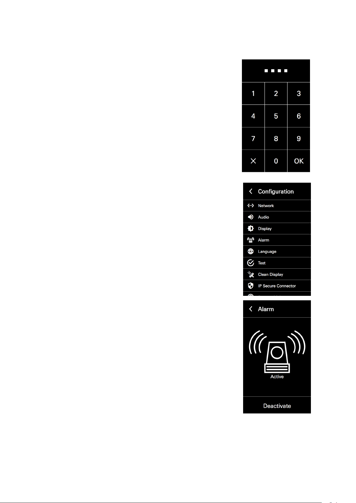
Commissioning instructions – Schüco DCS Touch Display 27
1. Tap the display (if the house number is displayed) and swipe left to
display the code entry.
2. Enter the administrator code („1234“ if it has not yet been changed)
and tap „OK“.
Schüco de
3. Select the „Alarm“ option.
4. Tap „Deactivate“ to avoid the DCS Touch Display from changing to the
alarm mode when it is tilted.
Proceed as follows to remove the Schüco DCS Touch Display:
1. Guide the unlocking nibs of the Schüco DCS Touch Display installation tool into the
top loudspeaker opening of the DCS Touch Display.
2. To release the unlocking mechanism, slide the DCS Touch Display installation tool upwards as far
as possible.
Dok-Nr.10000432116_01
Page 26

28
Schücode Commissioning instructions – Schüco DCS Touch Display
3. Carefully push the bottom end of the DCS Touch Display installation tool towards the DCS unit in
order to release the Schüco DCS Touch Display from its xed position.
4. Carefully remove the Schüco DCS Touch Display from the Schüco DCS unit. Disconnect the plug
from the device and remove the entire electronics assembly.
1
2 3
4 5
INFORMATION
The DCS Touch Display installation tool can also be used as a protective compartment to store
the DCS Touch Display.
Dok-Nr.10000432116_01
Page 27
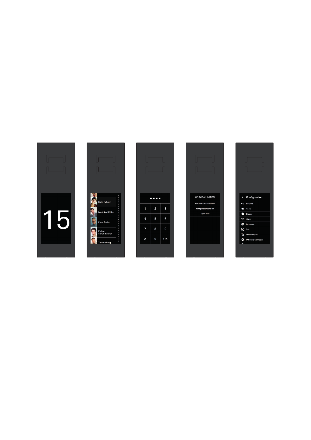
Commissioning instructions – Schüco DCS Touch Display 29
Schüco de
8. Screen surface
The DCS Touch Display can be operated via the 4.3 inch touchscreen.
The DCS Touch Display is divided into the following ve main screens (from left to right):
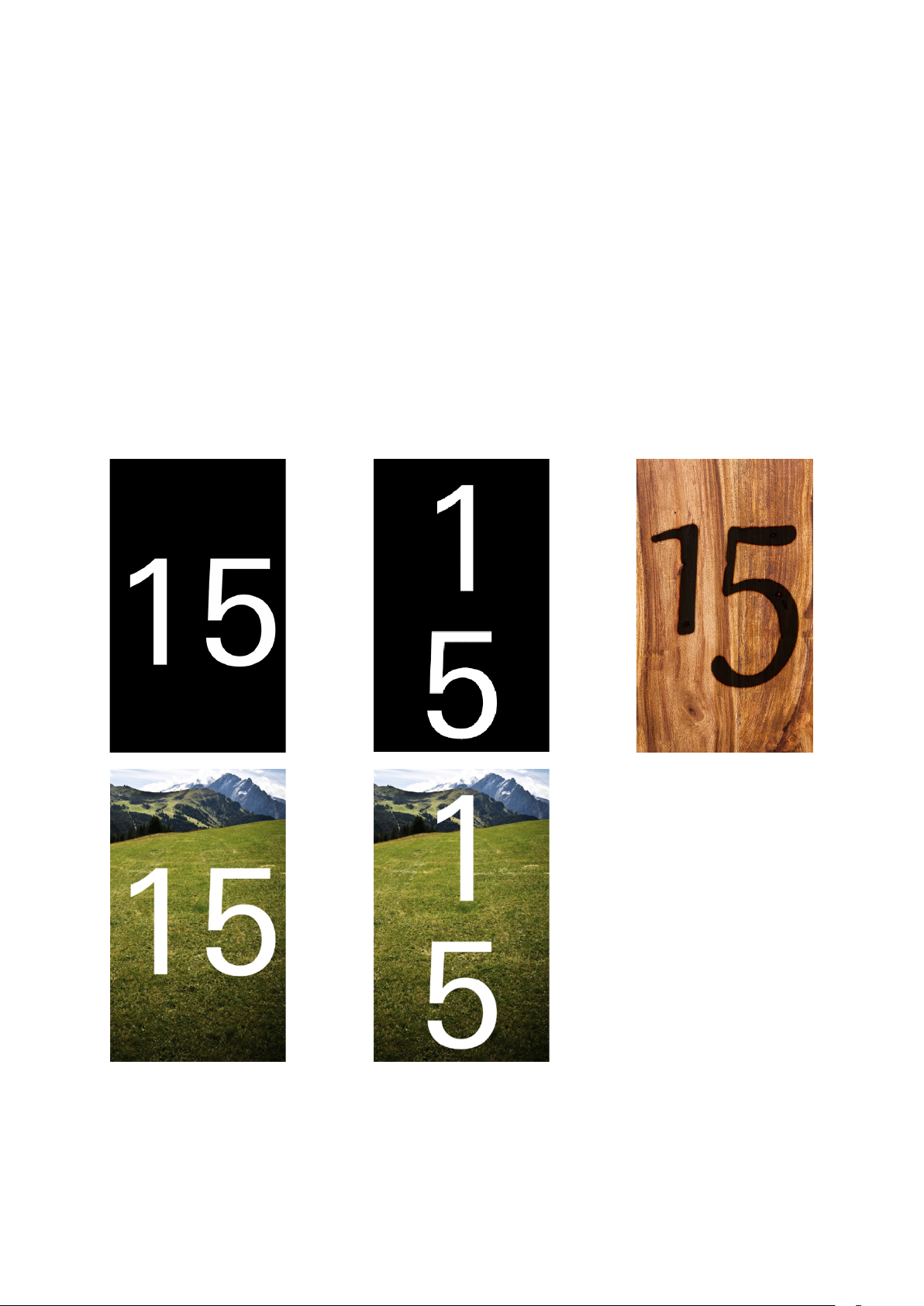
● Start screen: Here you can display the house number or any desired image in 480 x 800 pixel
format.
● Doorbell list: Here you can display all the contacts you can call or for whom a stored function can be
activated.
● Code entry: Here you can enter a four or six-digit access code in order to display the „Conguration“
view, for example.
● Select action: Here you can select one of several actions permitted for the user as applicable.
● Conguration: Here you can make basic settings directly on the DCS Touch Display.
Dok-Nr.10000432116_01
Page 28
30
Schücode Commissioning instructions – Schüco DCS Touch Display
8.1. Start screen
In the „Start screen“ view, the house number or an image can be displayed. To exit the „Idle“ device
status, the screen must be tapped or a movement detected by the integrated camera of a congured
motion detector (see „9.11 Motion detection“). For the „Start screen“ view, there are ve display
options (see „9.9 Device“):
● The house number alone is displayed horizontally.
● The house number alone is displayed vertically.
● Only an image is displayed.
● The house number is displayed horizontally along with an image. In this case, the house number
appears over the image in white font.
● The house number is displayed vertically along with an image. In this case, the house number
appears over the image in white font.
Dok-Nr.10000432116_01
Page 29
Commissioning instructions – Schüco DCS Touch Display 31
Schüco de
8.2. Doorbell list
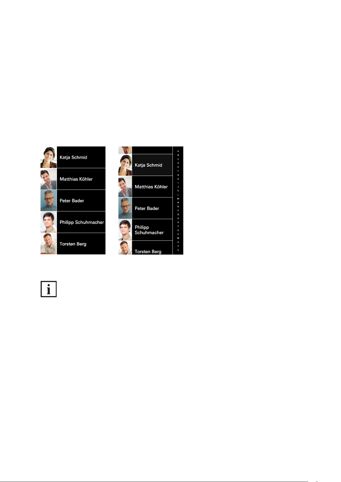
Tap the screen in standard conguration to switch to the „Doorbell list“ view. Here all contacts and action sequences are listed which have been congured in the web interface on the „Buttons“ page (see
„9.12 Buttons“). Depending on how many buttons have been congured, the screen of the DCS Touch
Display presents two different view options:
● View without scroll bar: If ve buttons or fewer have been congured, it is not possible to scroll up
and down the screen.
● View with scroll bar: If more than ve buttons have been congured, a scroll bar appears on the
right-hand side of the screen.
INFORMATION
Doorbell list display
Contacts in the „Doorbell list“ view can be sorted either by rst name or surname. The contacts in the
„Doorbell list“ view are listed according to the option which has been selected. The scroll bar on the
right of the DCS Touch Display screen only appears once the buttons have been sorted by rst name
or surname. You can nd more information about sorting contacts in the „Doorbell list“ view under
„9.15 Contacts“.
Dok-Nr.10000432116_01
Page 30
32
Schücode Commissioning instructions – Schüco DCS Touch Display
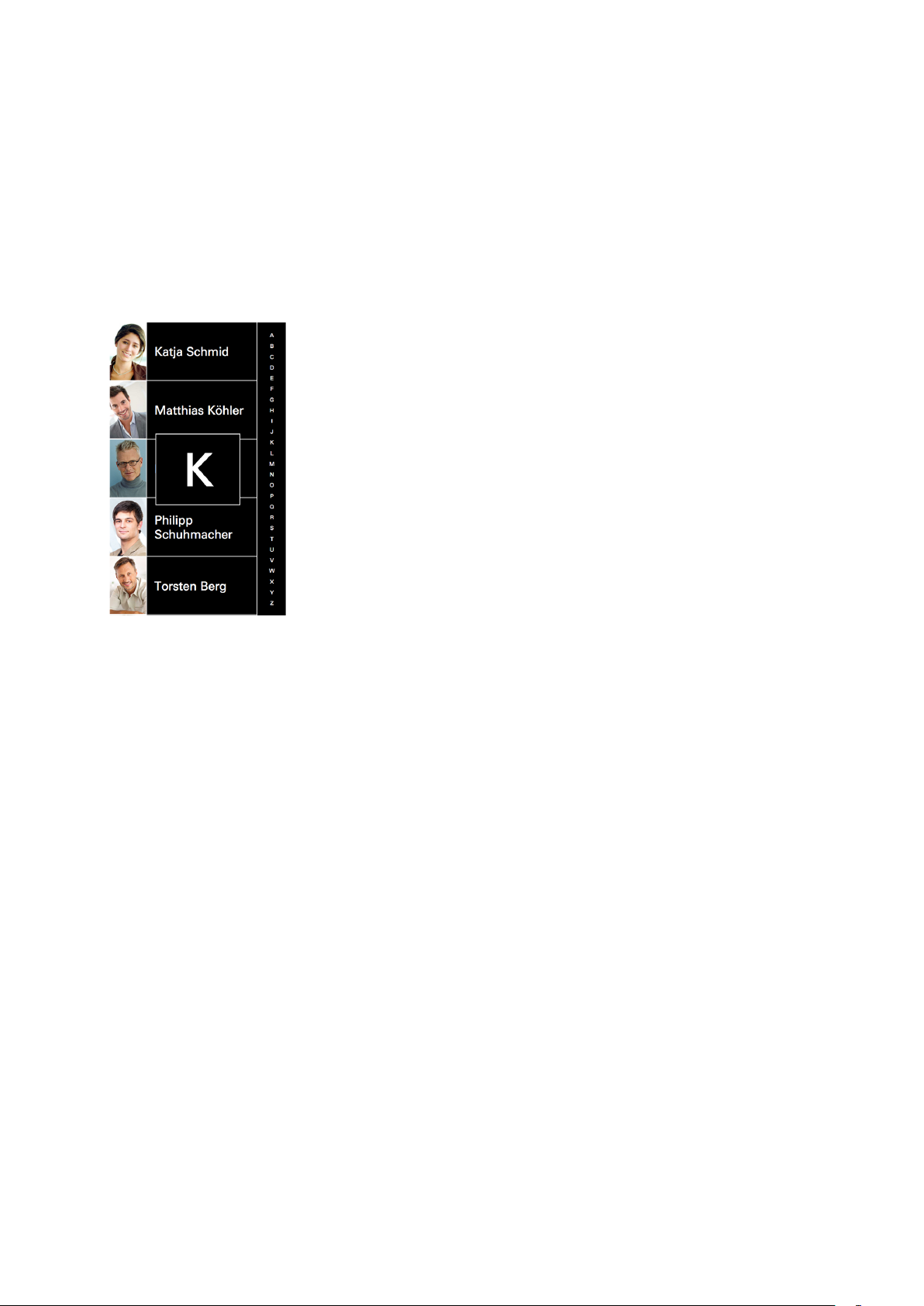
Proceed as follows to scroll through the „Doorbell list“ view:
1. For optimum scrolling upwards and downwards, position your nger in the middle of the scroll bar.
2. Swipe upwards or downwards. The alphabet on the scroll bar shows the direction in which you are
scrolling. In addition, the box in the middle of the screen shows which contacts are being shown
with which initial letters. Alternatively, you can also tap a letter in the scroll bar in order to move
directly to the desired initial letter.
Dok-Nr.10000432116_01
Page 31
Commissioning instructions – Schüco DCS Touch Display 33
Schüco de
8.2.1. Making a call
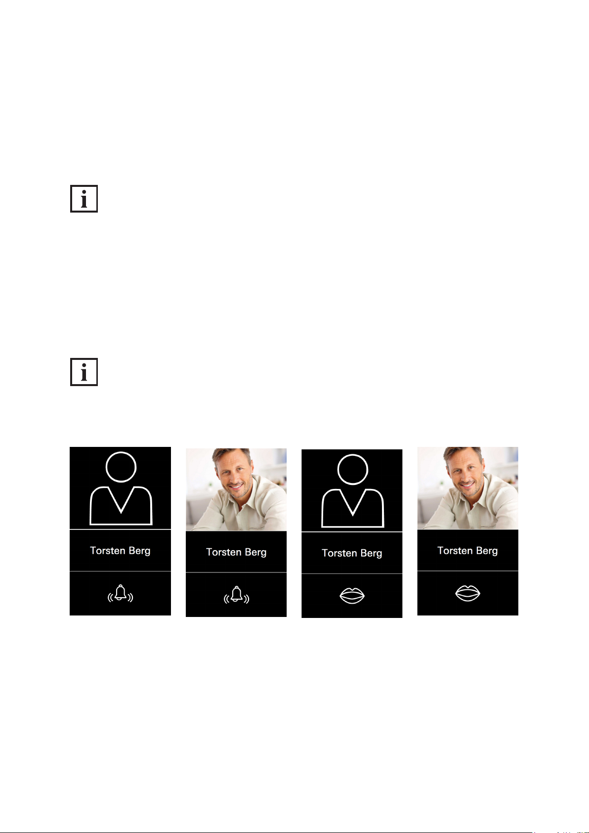
Tap the desired contact in order to make a call. Depending on how the counterpart intercom station
(e.g. SIP telephone, SIP app) was congured, the call is promptly accepted or ringing continues until
the call is accepted or automatically ended after a time-out of 45 seconds. In order to end a call
manually whilst calling a contact, you must tap the „Bell“ symbol in the bottom part of the screen.
INFORMATION
Calls
Calls are only possible once contacts have been created and the corresponding buttons have been
congured.
Corresponding to the two call statuses „Calling“ and „Talking“, there are two different views:
● Calling: The „Bell“ symbol in the bottom part of the screen makes clear that the counterpart intercom
station is ringing and that the call has not yet been accepted.
● Talking: The „Mouth“ symbol in the bottom part of the screen makes clear that the call has been
established and that dialogue can now begin.
INFORMATION
Prole picture
If no prole picture has been uploaded for the respective contact, the standard avatar is displayed.
Dok-Nr.10000432116_01
Page 32
34
Schücode Commissioning instructions – Schüco DCS Touch Display
8.2.2. Ending a call
Tap the „Mouth“ symbol in the bottom part of the screen to end the call. As soon as the call is ended
by you or the person at the counterpart intercom station, the DCS Touch Display shows the
„Doorbell list“ once again.
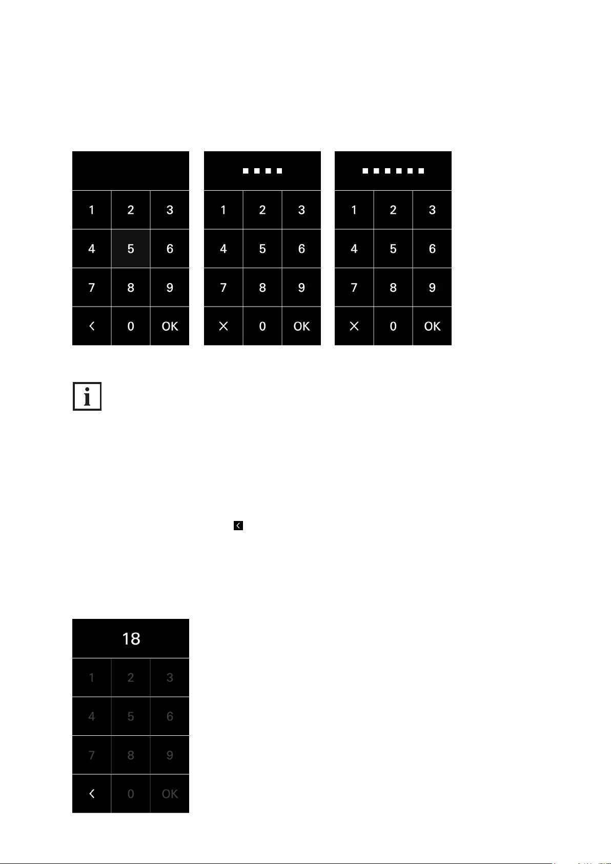
8.3. Entering the access code
Swipe to the left from the „Doorbell list“ view to display the „Code entry“ view. From here it is possible
to access the „Conguration“ view or trigger another, previously dened event (e.g. actuate a door
opener or deactivate an alarm system).
Besides the digits „0“ to „9“ for the access code, there are three further buttons:
Switch to the „Doorbell list“ view (alternatively you can swipe to the right).
Delete the last digit entered (if a digit has been entered, this button appears instead of the
button described above).
Conrm access code.
Dok-Nr.10000432116_01
Page 33
Commissioning instructions – Schüco DCS Touch Display 35
Schüco de
For security reasons, the „Code entry“ view allows access codes of up to eight digits to be entered.
However, only four or six-digit access codes can be generated in the web interface
(see „9.18.8 Changing the access code“).
INFORMATION
Incorrect access code
If an incorrect access code is entered, the squares which represent the access code digits will be
„shaken“ in an animation. After two seconds, these squares are faded out so that the code can be
entered afresh. If the access code has been entered incorrectly three times, you must wait for ve
seconds until a new entry is possible. For the fourth incorrect entry, the waiting time is 10 seconds;
for the fth incorrect entry, the waiting time is 20 seconds; and for the sixth incorrect entry, the waiting
time is 30 seconds. If the access code has been entered incorrectly more than seven times, you must
always wait for 60 seconds until a new entry is possible. During the waiting time, it is possible to
return to the „Doorbell list“ view via . If a correct access code is entered in between times,
the waiting time is reset once more.
Dok-Nr.10000432116_01
Page 34
36
Schücode Commissioning instructions – Schüco DCS Touch Display
If the access code entered was correct, there are two options:
1. If the user has only been granted permission for one action sequence, this is carried out
immediately (e.g. actuate the door opener or display the „Conguration“ view).
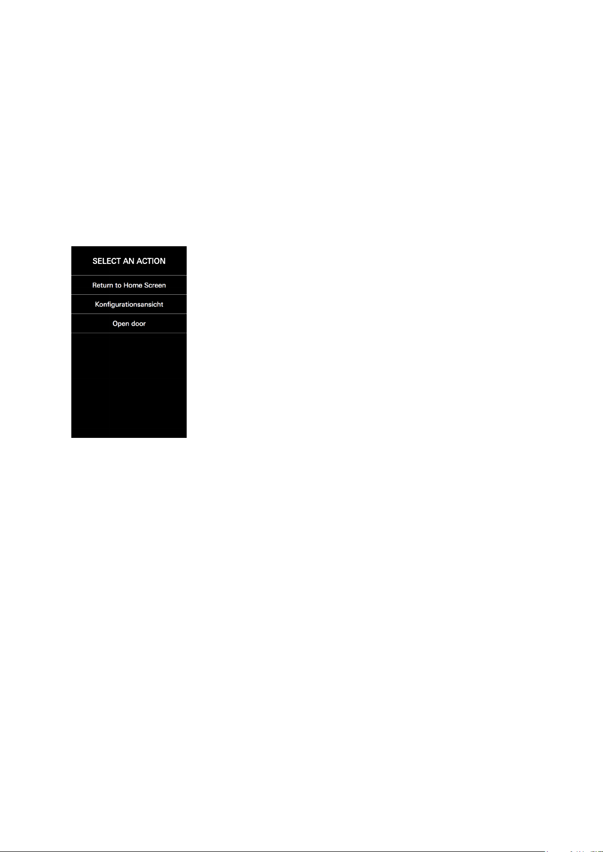
2. If the user has been granted permission for more than one action sequence, the „Select action“
view appears, where it is possible to select one of several action sequences (e.g. „Open door“ or
„Conguration view“) or switch to the „Start screen“ view via the option „Back to start screen“
(see „8.5 Select action“).
Dok-Nr.10000432116_01
Page 35
Commissioning instructions – Schüco DCS Touch Display 37
Schüco de
8.4. Conguration
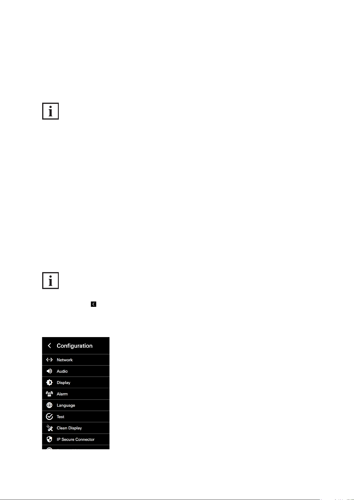
Enter your personal access code or the access code of the administrator in the „Code entry“ view
in order to display the „Conguration“ view. Here it is possible to make different settings directly on
the DCS Touch Display.
INFORMATION
Standard administrator code
The standard code for the administrator is „1234“. It is recommended that you change this as soon as
possible (see „9.18.8 Changing the access code“).
The following options are available in the „Conguration“ view:
● Network: Here you can assign an IP address for the DCS Touch Display.
● Audio: Here you can set the output volume („Loudspeaker“) and input volume („Microphone“).
● Screen: Here you can set the brightness of the screen.
● Alarm: Here you can activate or deactivate the anti-theft device.
● Language: Here you can set the screen language of the DCS Touch Display.
● Test: Here you can initiate the self-test for the DCS Touch Display.
● Clean display: Here you can deactivate the screen of the DCS Touch Display for 30 seconds.
● IP secure connector: Here the DCS Touch Display can be paired with or separated from an
IP secure connector.
● Remote maintenance: Here you can activate remote maintenance for support purposes.
INFORMATION
Back to start screen
Tap in the top left in order to switch to the „Start screen“ view.
Dok-Nr.10000432116_01
Page 36

38
Schücode Commissioning instructions – Schüco DCS Touch Display
8.4.1. Error messages
The DCS Touch Display displays error messages in the form of message boxes in the bottom part of
the screen as soon as an error has been detected (e.g. connection errors, incorrect conguration or
server errors). In this case check the conguration.
Dok-Nr.10000432116_01
Page 37
Commissioning instructions – Schüco DCS Touch Display 39
Schüco de
8.4.2. Network
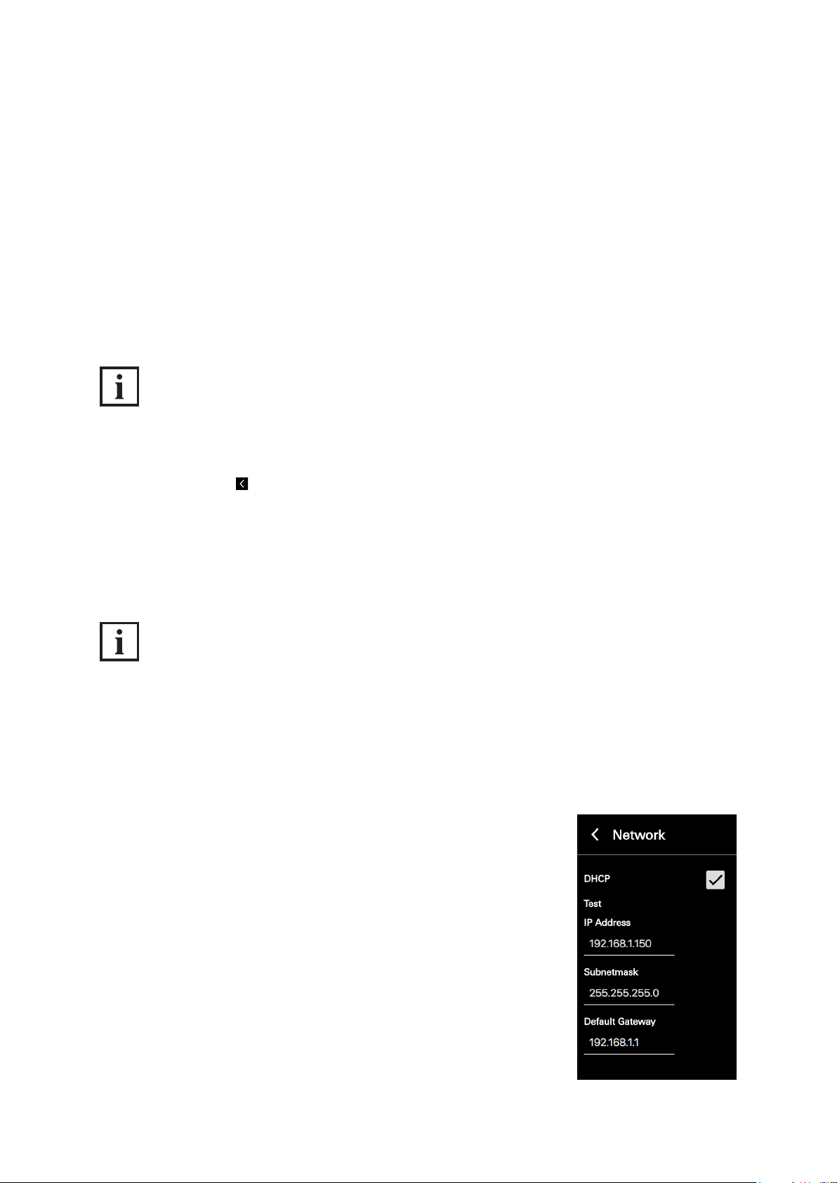
In the „Network“ conguration view, it is possible to assign an IP address to the DCS Touch Display.
The following options are available for this:
● DHCP: If this checkbox is checked, the DCS Touch Display automatically searches for a free
IP address in the building‘s network, the corresponding subnet mask and the default gateway.
This information is then displayed in the „IP address“, „Subnet mask“ and „Default gateway“ eld.
● IP address: Here you can enter the IP address of the DCS Touch Display.
● Subnet mask: Here you can enter the corresponding subnet mask for the IP address.
● Default gateway: Here you can enter the corresponding default gateway for the IP address
INFORMATION
Assigning an IP address
Only IPv4 addresses can be assigned to the DCS Touch Display. Manually assigned IP addresses are
only assigned to the DCS Touch Display once you tap „Save“. In order to discard an entry, you can
either tap „Cancel“ or .
On delivery, DHCP is activated for the DCS Touch Display. If a DHCP server has been found,
the DCS Touch Display displays the information in the „IP address“, „Subnet mask“ and „Default
gateway“ elds. Proceed as follows to manually assign an IP address to the DCS Touch Display:
INFORMATION
DHCP
This enables the assignment of the network conguration by means of a server (e.g. DSL router).
On delivery, DHCP is activated for the DCS Touch Display. If a DHCP server has been found, the
DCS Touch Display displays the information in the „IP address“, „Subnet mask“ and „Default gateway“
elds. Proceed as follows to manually assign an IP address to the DCS Touch Display:
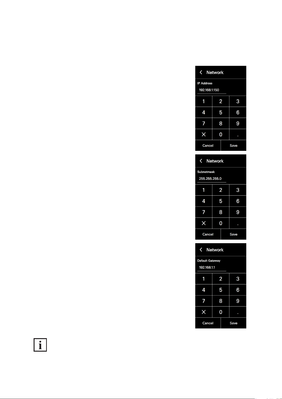
1. Open the „Network“ conguration view.
2. Tap the „DHCP“ checkbox to remove the checkmark.
Dok-Nr.10000432116_01
Page 38
40
Schücode Commissioning instructions – Schüco DCS Touch Display
3. Tap the „IP address“ eld and enter an IP address using the keypad
that appears.
4. Tap „Save“.
5. Repeat steps „2“ and „3“ for the „Subnet mask“ and „Default gateway“
elds.
INFORMATION
DHCP function activated
While the „DHCP“ checkbox is checked, it is not possible to amend the „IP address“, „Subnet mask“
and „Default gateway“ elds.
Dok-Nr.10000432116_01
Page 39
Commissioning instructions – Schüco DCS Touch Display 41
Schüco de
8.4.3. Audio
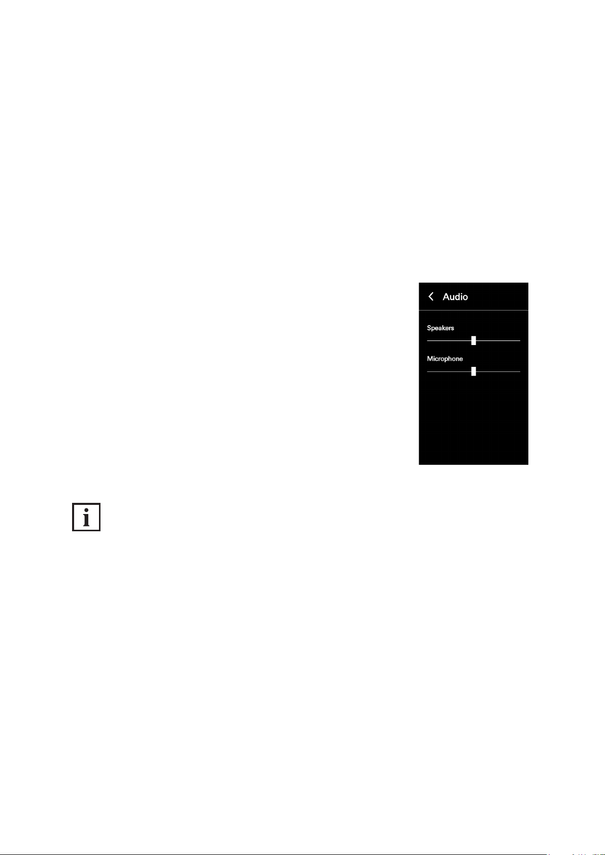
In the „Audio“ conguration view, it is possible to make basic audio settings on the
DCS Touch Display. The following options are available for this:
● Loudspeaker: Here you can adjust the output volume of the loudspeaker on the DCS Touch Display.
Here the value is set to the middle value as standard. By moving the slider right, you can increase
the volume; by moving the slider left, you can decrease it.
● Microphone: Here you can adjust the degree of preamplication of the microphone on the
DCS Touch Display. Here the value is set to the middle value as standard. By moving the slider
right, you can increase the volume; by moving the slider left, you can decrease it.
Proceed as follows to adjust the volume settings on the DCS Touch Display:
1. Open the „Audio“ conguration view.
2. Adjust the volume by means of the „Loudspeaker“ and/or „Microphone“
controls.
INFORMATION
Applying settings
Settings are applied and saved immediately when adjusting a control.
Display of the value
The set value is displayed only in the web interface and not on the screen of the DCS Touch Display.
Dok-Nr.10000432116_01
Page 40
42
Schücode Commissioning instructions – Schüco DCS Touch Display
8.4.4. Screen
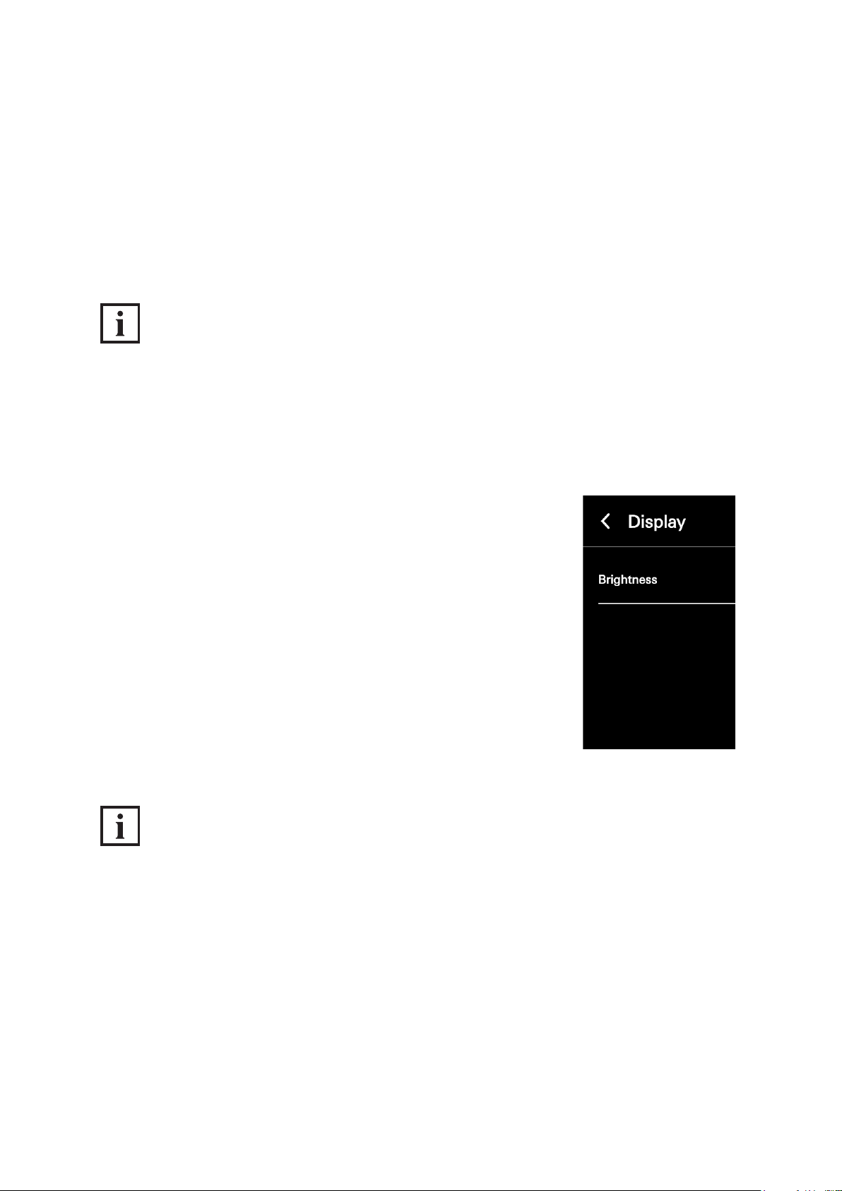
In the „Screen“ conguration view, it is possible to set the brightness for the screen on the
DCS Touch Display. The following option is available for this:
● Brightness: Here you can adjust the brightness of the screen on the DCS Touch Display between
„0“ and „100“. Here the value is set to „80“ as standard.
INFORMATION
Display of the value
The set value is displayed only in the web interface and not on the screen of the DCS Touch Display.
Proceed as follows to adjust the screen brightness in the DCS Touch Display:
1. Open the „Screen“ conguration view.
2. Adjust the brightness by means of the „Brightness“ control.
INFORMATION
Applying settings
Settings are applied and saved immediately when adjusting the control.
Dok-Nr.10000432116_01
Page 41
Commissioning instructions – Schüco DCS Touch Display 43
Schüco de
8.4.5. Alarm
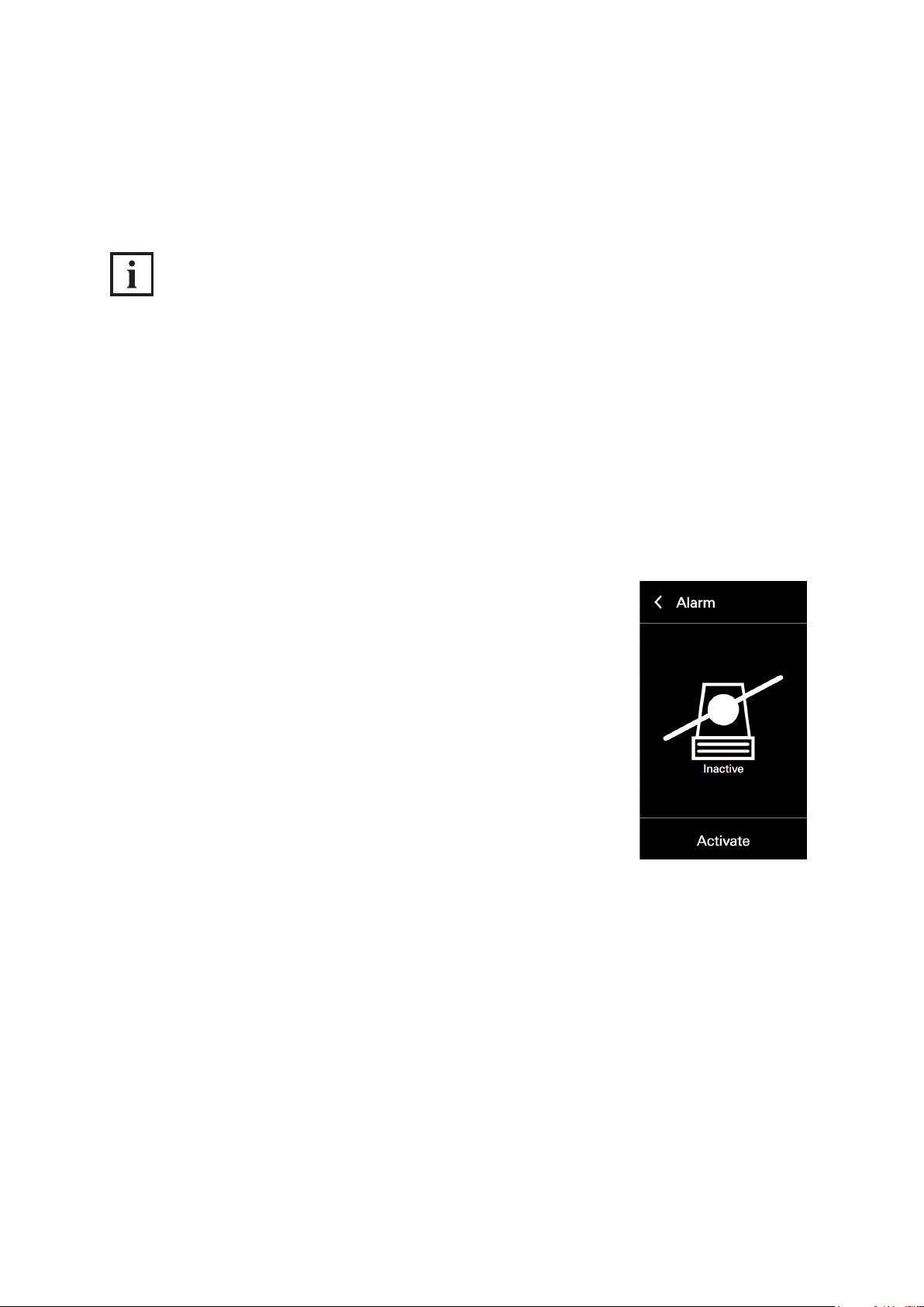
In the „Alarm“ conguration view, it is possible to activate the anti-theft device or to deactivate it for the
removal of the DCS Touch Display.
INFORMATION
Anti-theft device
It is essential that you observe the steps for deactivating the anti-theft device prior to removal,
as otherwise the alarm mode will be activated. If the DCS Touch Display is paired with an
IP secure connector in the alarm mode, the network connection and the PoE+ power supply between
the IP secure connector and the DCS Touch Display will be disconnected after 30 seconds when an
attempt is made to remove the DCS Touch Display incorrectly. In this way, any unauthorised access
from outside via this network cable is successfully prevented. To enable recommissioning of the
DCS Touch Display, it must be put back in its original position and the „PAIRING“ button pressed on
the IP secure connector. If necessary, the anti-theft device must be reactivated, as this function is
deactivated in the alarm mode.
Proceed as follows to activate the anti-theft device of the DCS Touch Display:
1. Open the „Alarm“ conguration view.
2. Tap „Activate“.
Dok-Nr.10000432116_01
Page 42
44
Schücode Commissioning instructions – Schüco DCS Touch Display
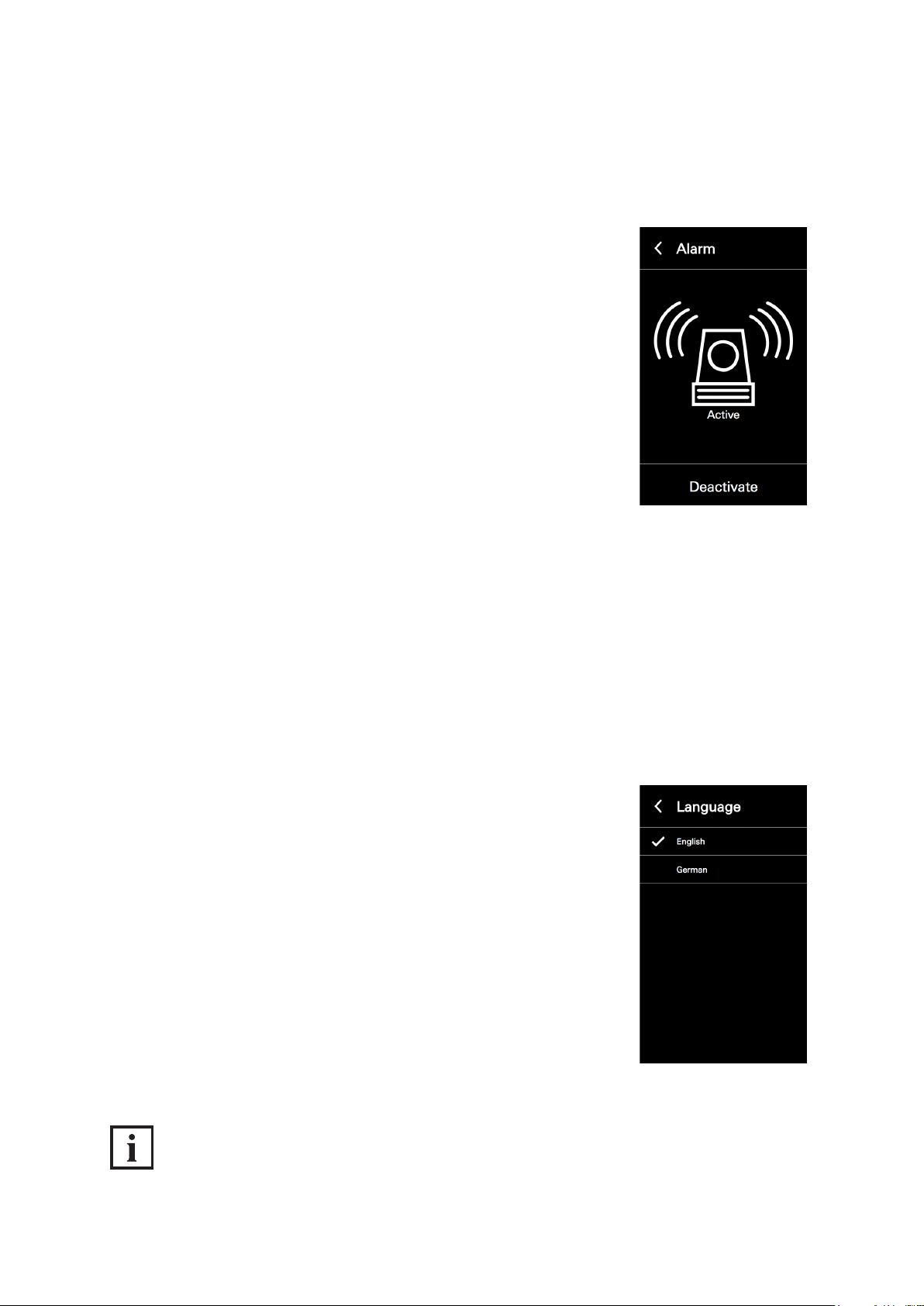
Proceed as follows to deactivate the anti-theft device of the DCS Touch Display:
1. Open the „Alarm“ conguration view.
2. Tap „Deactivate“ to avoid the DCS Touch Display from switching to the
alarm mode when it is removed.
8.4.6. Language
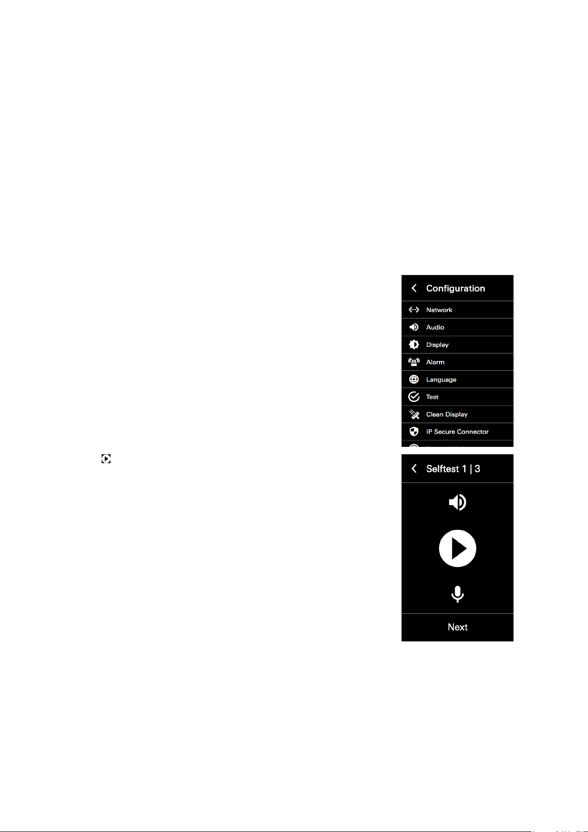
In the „Language“ conguration view, it is possible to set the screen language of the
DCS Touch Display. The following options are available for this:
● German
● English
Proceed as follows to set the language on the DCS Touch Display:
1. Open the „Language“ conguration view.
2. Tap the desired language.
INFORMATION
Applying settings
Settings are applied and saved by tapping an option.
Dok-Nr.10000432116_01
Page 43
Commissioning instructions – Schüco DCS Touch Display 45
Schüco de
8.4.7. Test
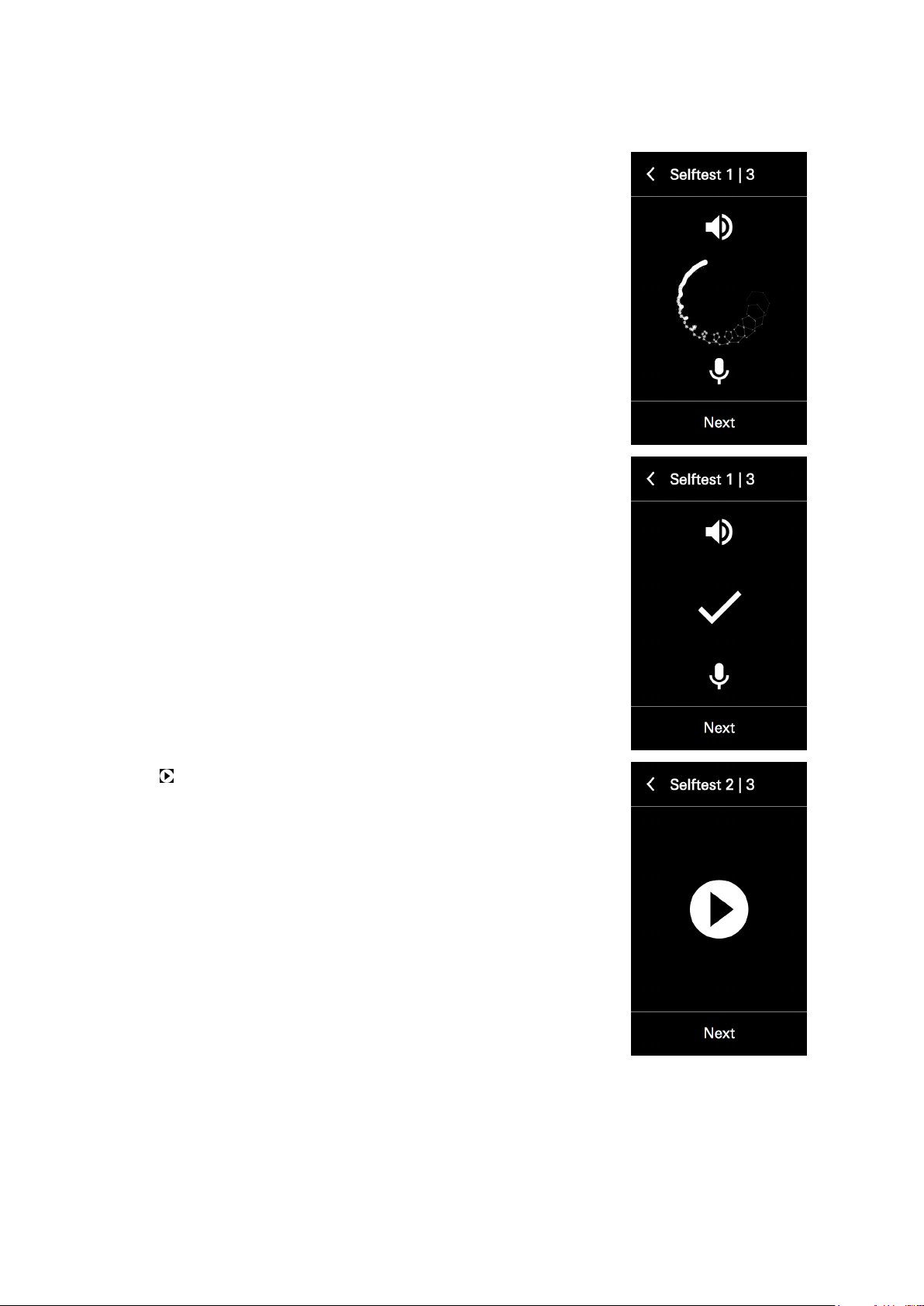
In the „Test“ conguration view, it is possible to perform the self-test for the DCS Touch Display.
This is subdivided into the following three steps:
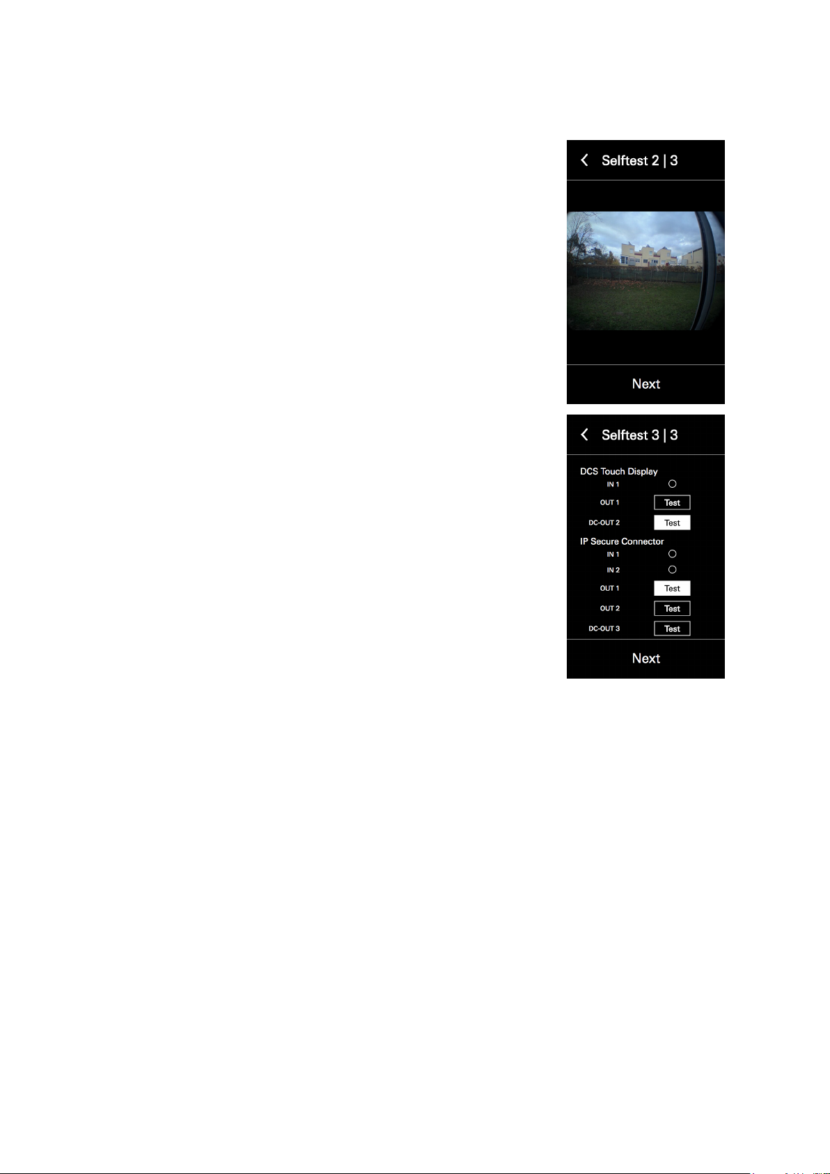
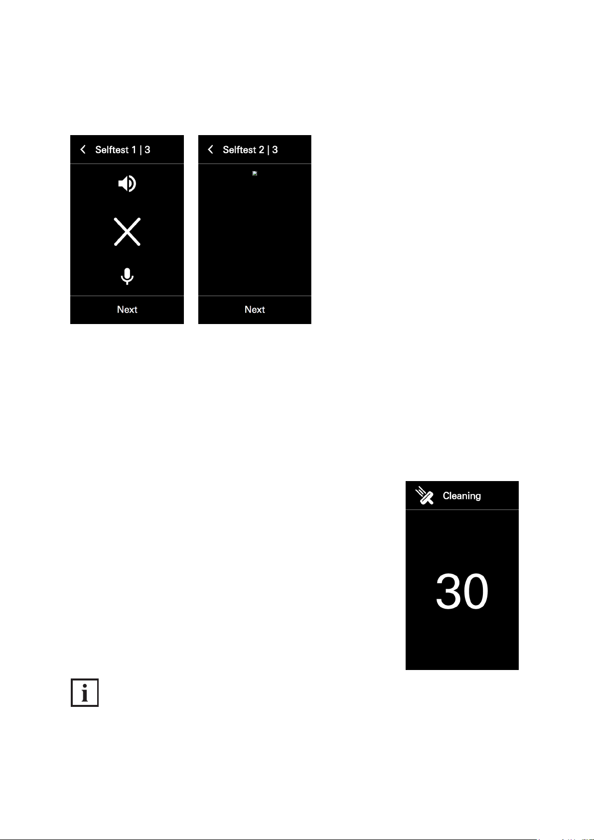
● Self-test 1/3 (audio): Here the loudspeaker and microphones of the DCS Touch Display can be test-
ed for perfect functionality.
● Self-test 2/3 (video): Here the image from the internal camera can be displayed on the screen of the
DCS Touch Display.
● Self-test 3/3 (I/Os - inputs and outputs): Here it is possible to see which connections are occupied,
and which outputs can be switched.
Proceed as follows to start and end the self-test on the Schüco DCS Touch Display:
1. Open the „Test“ conguration view.
2. Tap to start the audio test. A noise signal is now emitted via the loudspeaker, which is recorded by the microphones and then analysed.
Dok-Nr.10000432116_01
Page 44
46
Schücode Commissioning instructions – Schüco DCS Touch Display
3. During this time, an animation is played on the screen. If an audio test is
successful, a checkmark is displayed in the middle of the screen.
4. Tap „Next“.
5. Tap to start the video test.
Dok-Nr.10000432116_01
Page 45
Commissioning instructions – Schüco DCS Touch Display 47
6. If a video test is successful, the video image from the internal camera
is displayed on the screen. It may be that the video image is displayed
with a time delay. However, it is free from faults if a video image can be
seen.
7. Tap „Next“. The I/O test is started.
Schüco de
8. If an output has been switched or an altered input value recognised, the
button of the corresponding input or output is highlighted in white.
9. Tap „Test“ next to the desired output to activate a door opener con-
nected to it, for example.
10. Tap „Next“ to nish the self-test.
Dok-Nr.10000432116_01
Page 46
48
Schücode Commissioning instructions – Schüco DCS Touch Display
If the audio test was unsuccessful, an „X“ is displayed instead of a checkmark.
If the video test was unsuccessful, the screen remains black.
8.4.8. Cleaning the display
In the „Clean display“ conguration view it is possible to deactivate the screen of the
DCS Touch Display for 30 seconds. This prevents any buttons on the screen from being pressed inadvertently during cleaning (e.g. wiping with a cloth). While the screen is deactivated, a countdown can
be seen. As soon as this has run down, the screen switches back to the „Conguration“ view.
Proceed as follows to deactivate the screen of the DCS Touch Display for 30 seconds:
1. Open the „Clean display“ conguration view.
INFORMATION
Cleaning
The screen is immediately deactivated when the „Clean display“ conguration view has been called
up. For information on cleaning, see „12 Maintenance and cleaning“.
8.4.9. IP secure connector
Dok-Nr.10000432116_01
Page 47
Commissioning instructions – Schüco DCS Touch Display 49
Schüco de
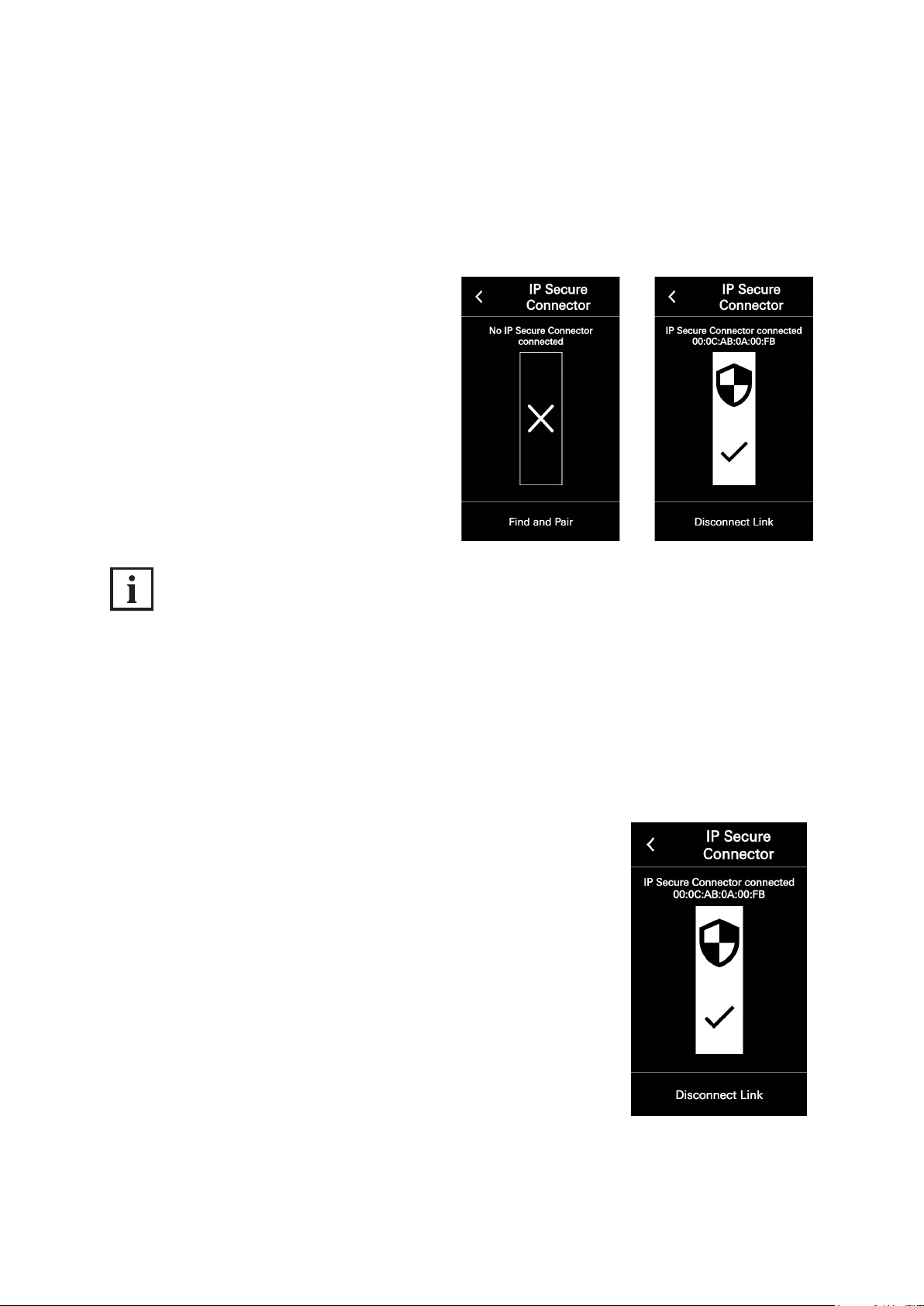
In order to connect the DCS Touch Display to an associated IP secure connector, it is necessary to
search for the IP secure connector. If the DCS Touch Display or the IP secure connector is removed
or replaced, the connection must be dissolved once more. If no IP secure connector is provided for
the installation, you can skip this point.
To connect the DCS Touch Display to an IP secure connector, proceed as follows:
1. Open the „IP secure connector“ conguration
view.
2. Tap „Search and connect“. Once the
DCS Touch Display is connected to an
IP secure connector, the message
„Connected to IP secure connector (serial
number)“ appears.
INFORMATION
No IP secure connector found
If no IP secure connector is connected to the DCS Touch Display or the „Search and connect“ button
has not yet been pressed since an IP secure connector has been connected to the
DCS Touch Display, the message „No IP secure connector connected“ can be seen on the screen.
To disconnect the DCS Touch Display from an IP secure connector, proceed as follows:
3. Open the „IP secure connector“ conguration view.
4. Tap „Disconnect connection“.
Dok-Nr.10000432116_01
Page 48
50
Schücode Commissioning instructions – Schüco DCS Touch Display
INFORMATION
IP secure connector cannot be found
If an IP secure connector that is already connected can no longer be found, the message
„Cannot be found“ is displayed next to its serial number. In addition, a large exclamation mark can be
seen in the pictogram. In this case, check the ethernet connection and the power supply of the
IP secure connector. If the IP secure connector has been removed and a new one installed,
disconnect the connection and connect the new IP secure connector to the DCS Touch Display.
8.4.10. Remote maintenance
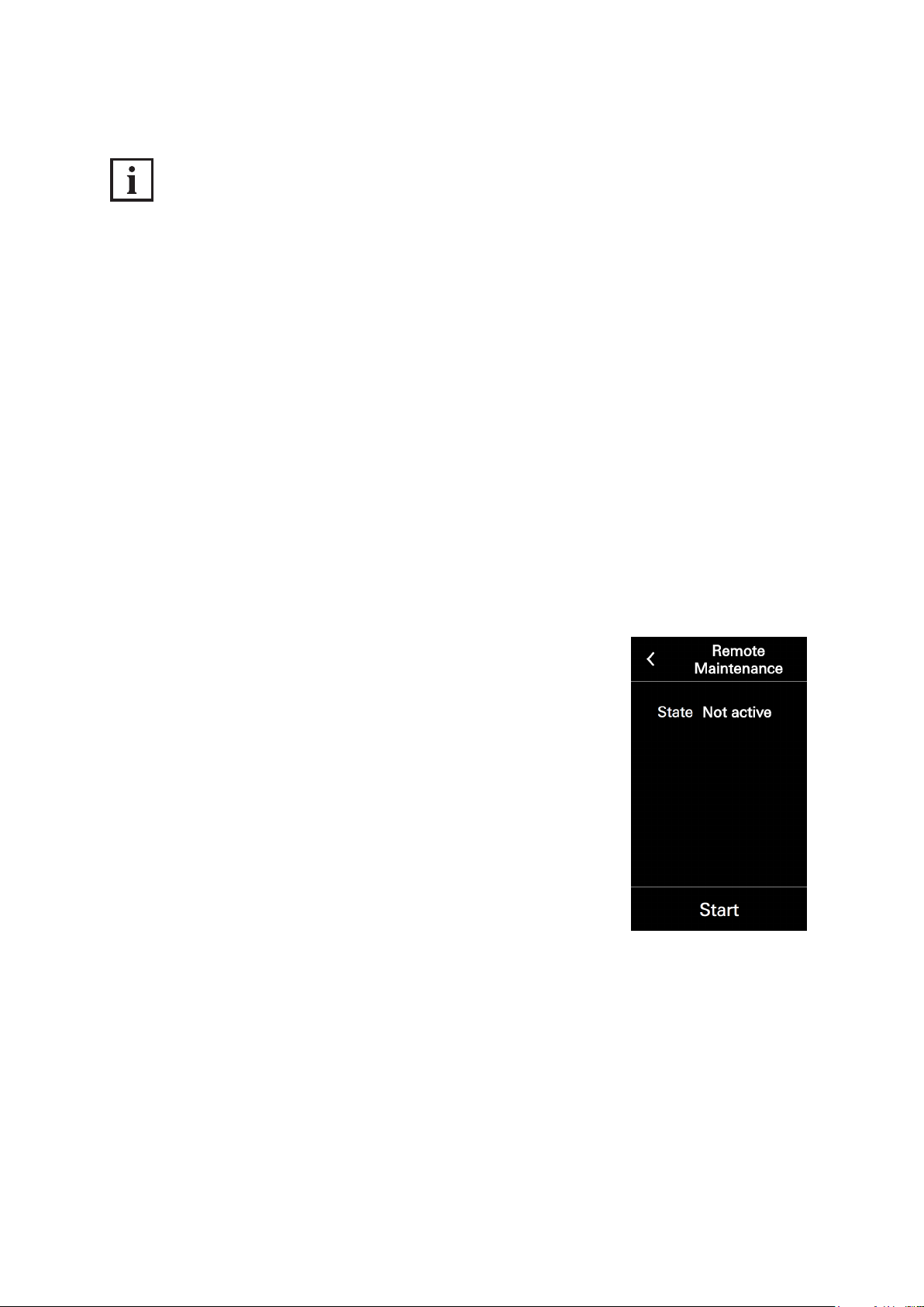
It is possible for Support to carry out remote maintenance on the DCS Touch Display.
For this purpose, the „Remote maintenance“ function must be activated.
The following information is available in the „Network status“ section:
● Status: Here the status of the remote maintenance is displayed.
To start and stop remote maintenance for support purposes, proceed as follows:[ ]
1. Open the „Remote maintenance“ conguration view.
2. Tap „Start“. The status changes to „Started“ and two port numbers
are displayed.
Dok-Nr.10000432116_01
Page 49
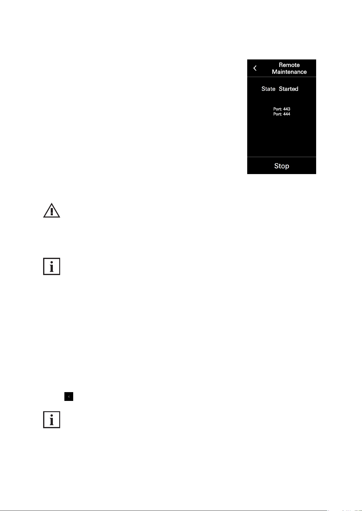
3. Tap „Stop“. The status changes to „Not active“.
Commissioning instructions – Schüco DCS Touch Display 51
Schüco de
NOTE
Damage to property.
► Do not stop remote maintenance under any circumstances unless you are told to do so
by Support.
INFORMATION
Safety information
The remote maintenance is not a permanent interface for contacting Schüco. Use of this interface
requires the express approval of the system operator/person responsible for the system on site.
8.4.11. Close conguration
Via the arrow at the top left, it is possible to switch from the „Conguration“ view to the
„Doorbell list“ view.
To leave the „Conguration“ view and switch to the „Doorbell list“ view, proceed as follows:
1. Tap „Stop“ to deactivate remote maintenance, as otherwise the remote maintenance will remain
active.
2. Tap . .
INFORMATION
Leaving conguration
After switching to the „Doorbell list“ view via the „Close conguration“ button, it is necessary to enter
the access code again in the „Code entry“ view in order to call up the „Conguration“ view once more.
Dok-Nr.10000432116_01
Page 50
52
Schücode Commissioning instructions – Schüco DCS Touch Display
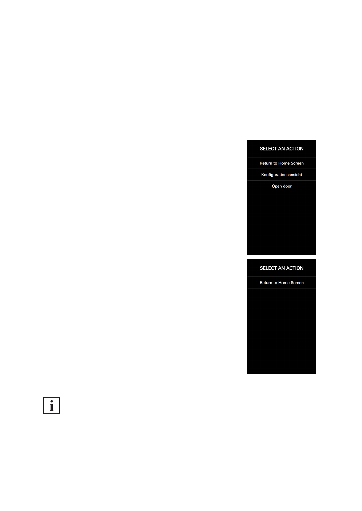
8.5. Select action
If multiple action sequences have been stored for a single user, the “Select action” view appears after
the access code is entered. In the “Select action” view, it is possible to carry out an action sequence
or return to the “Start screen” view.
To select an action sequence or return to the “Start screen” view, proceed as follows:
Tap a button with a stored action sequence (e.g. “Call up conguration” or “Actuate door opener”) or
tap the “Return to home screen” button.
1. Tap a button with a stored action sequence (e.g. „Open door“ or „Conguration view“) or tap „Back to start screen“.
If no action sequences have been stored for the user, the „Select action“
view appears with „Back to start screen“ as the sole option.
INFORMATION!
Only one action sequence stored
If only one action sequence has been stored for the user, this is performed immediately without the
„Select action“ view being displayed rst.
Dok-Nr.10000432116_01
Page 51
Commissioning instructions – Schüco DCS Touch Display 53
Schüco de
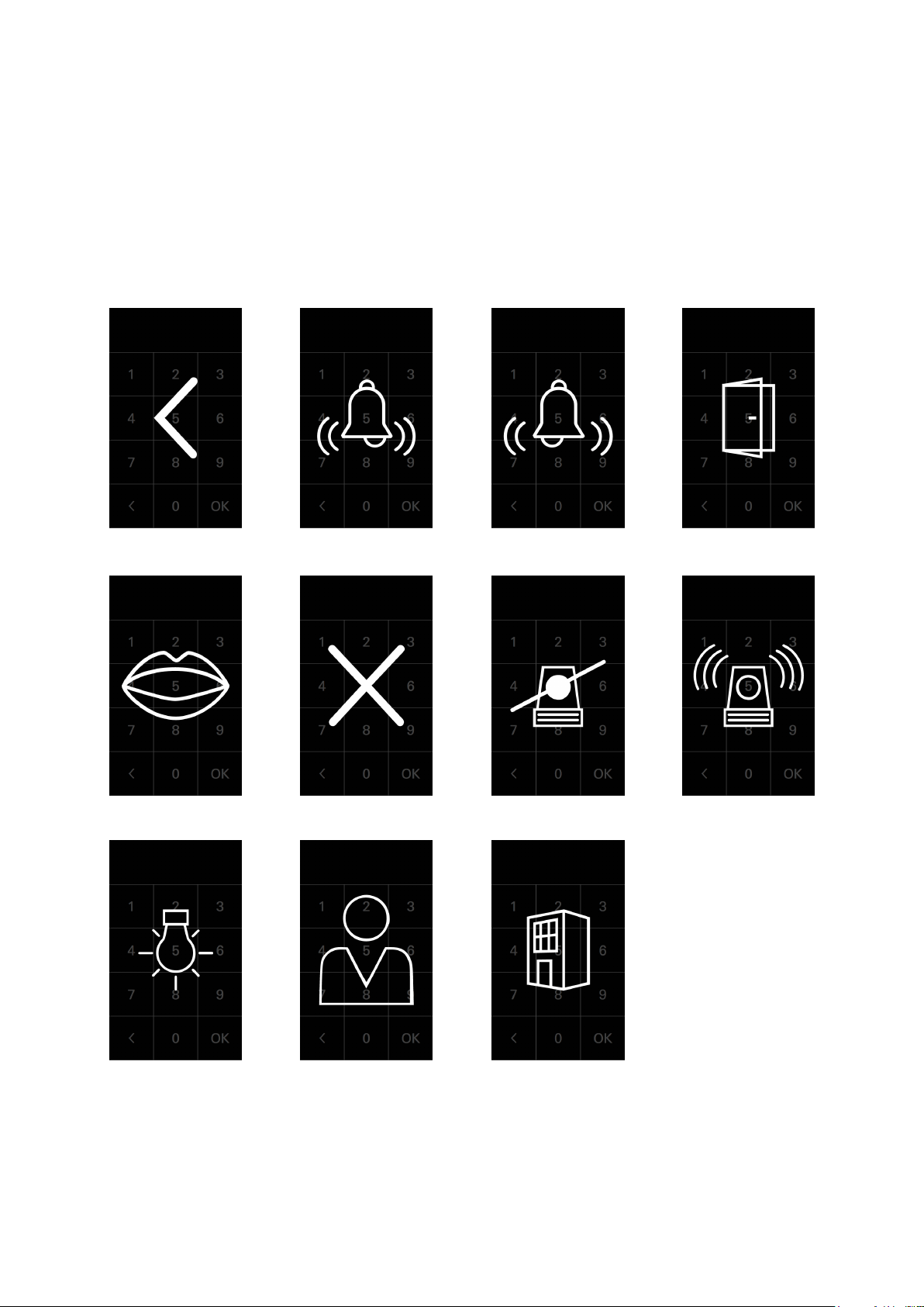
8.6. Symbols
The DCS Touch Display can display seven different symbols in total. Depending on the congured
action sequence, these are displayed either immediately after the access code is entered or after an
action sequence is selected.
The following symbols are available:
Arrow
Door Bell left Bell right
Alarm on Alarm off X Mouth
Dok-Nr.10000432116_01
Building Avatar Light
Page 52
54
Schücode Commissioning instructions – Schüco DCS Touch Display
INFORMATION
Symbol view
For as long as a symbol is displayed, the screen of the DCS Touch Display is deactivated.
The time for which a symbol is displayed depends on the conguration of the action sequence.
9. Web interface
The web interface is a browser-based application via which it is possible to congure the
DCS Touch Display and the IP secure connector as well as read all relevant data.
INFORMATION
Recommended browser
The web interface can generally be used with all browsers. It is recommended, however, that you use
the most up-to-date version of Google Chrome.
Dok-Nr.10000432116_01
Page 53
Commissioning instructions – Schüco DCS Touch Display 55
Schüco de
9.1. Accessibility
As soon as the DCS Touch Display is connected to the building‘s network, the web interface can be
called up from any computer within the network (see „9.2 Calling up the web interface“).
INFORMATION
Ability to be called up
The web interface of the DCS Touch Display can only be called up after the device has booted up.
If the connection between the DCS Touch Display and the building‘s network is broken while the web
interface is open, the web interface will indicate that this has occurred with the symbol in the top
right section of the browser next to „log in“ and „log out“. As soon as there is once more a connection
between the DCS Touch Display and the building‘s network, the symbol will be hidden again.
9.2. Calling up the web interface
To be able to call up the web interface, the IP address of the DCS Touch Display is necessary.
This must be entered in the address bar of the browser (e.g. „192.168.1.150“).
If the IP address is not known, it can be displayed on the DCS Touch Display.
Proceed as follows to display the IP address on the DCS Touch Display and then call up the web
interface:
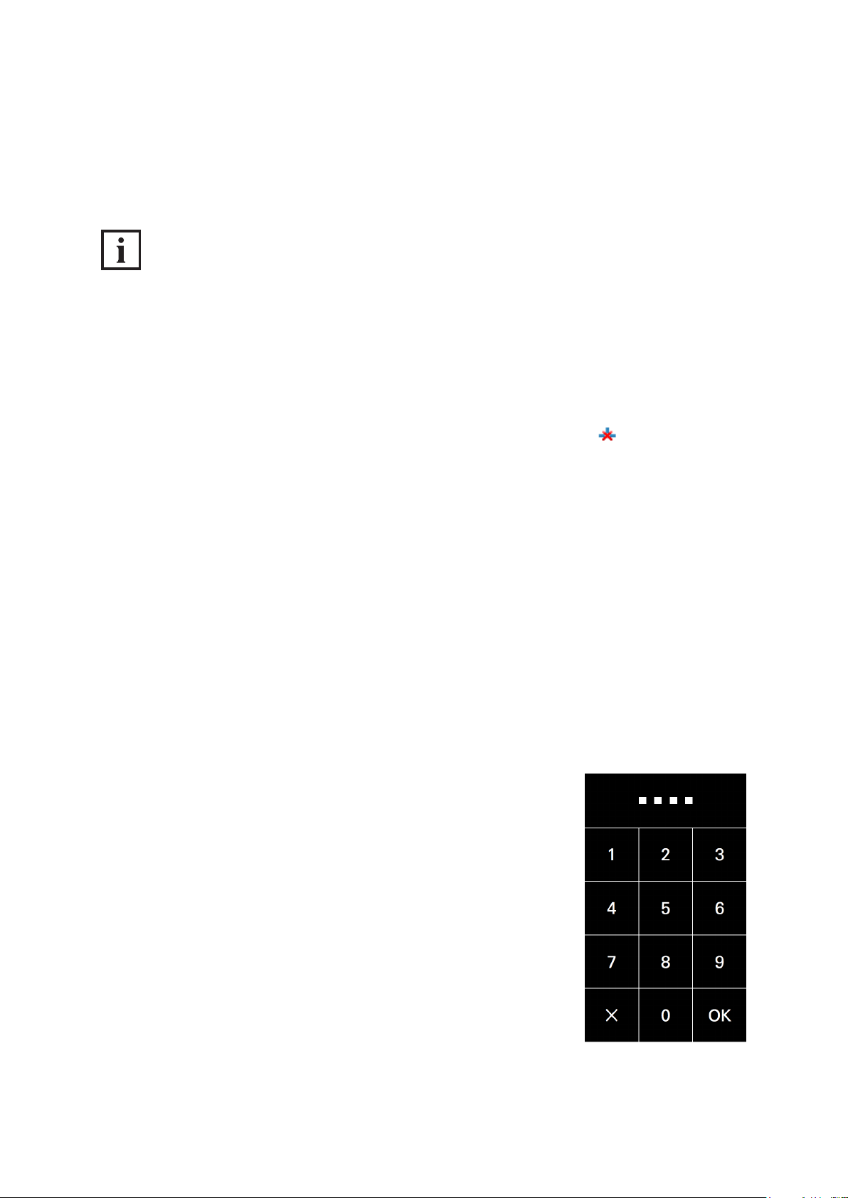
1. Tap the display and swipe to the left to call up the „Code entry“ view. Tap the screen and swipe to
the left to display the „Code entry“ view.
2. Enter the administrator access code and tap „OK“.
Dok-Nr.10000432116_01
Page 54
56
Schücode Commissioning instructions – Schüco DCS Touch Display
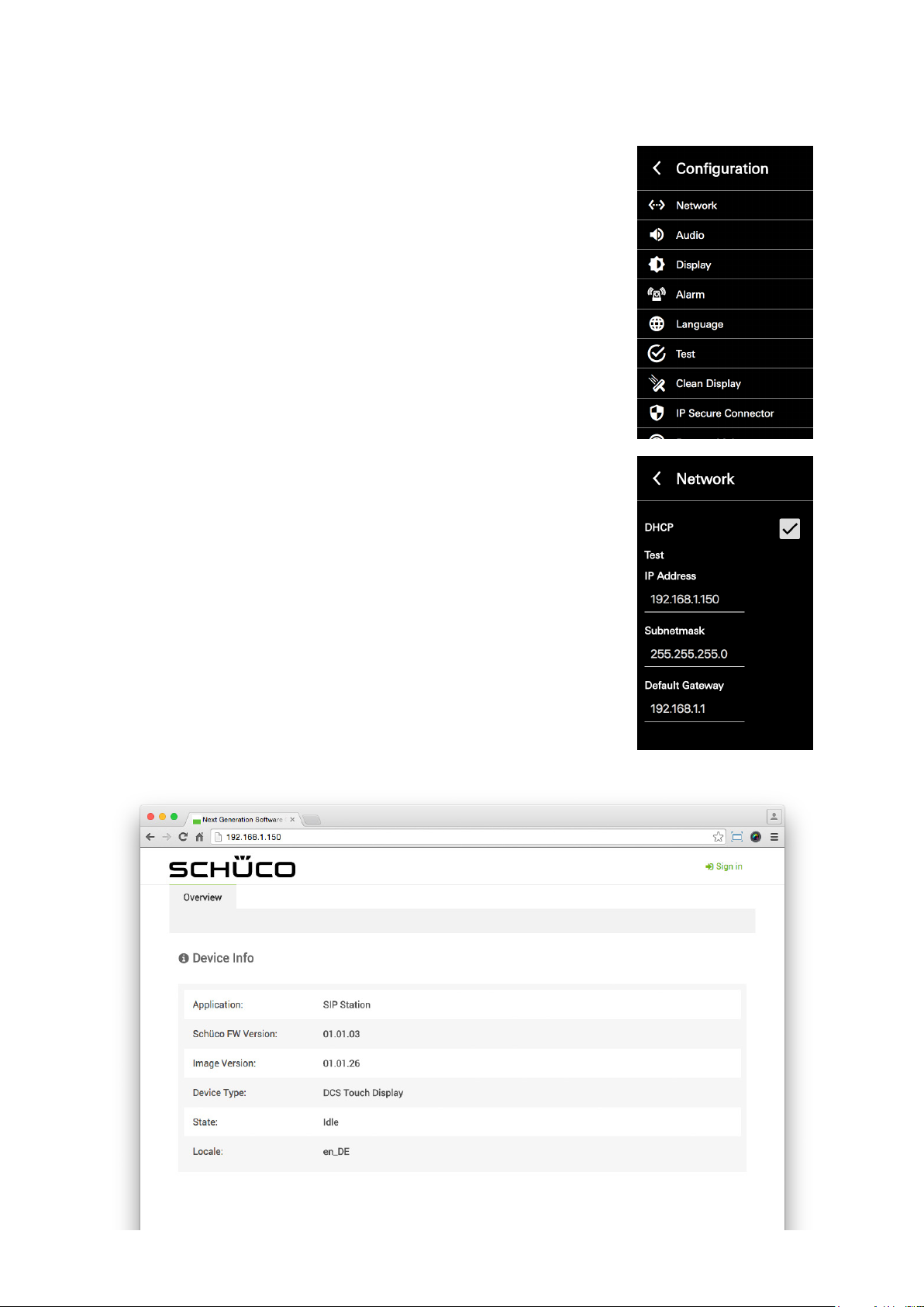
3. If there are multiple action sequences to select from, tap „Conguration
view“.
4. Open the „Network“ conguration view.
5. Note the IP address and enter this into your browser (e.g.
„192.168.1.150“). If the web interface can be reached by means of
your browser, the homepage will be dislpayed.
Dok-Nr.10000432116_01
Page 55
Commissioning instructions – Schüco DCS Touch Display 57
Schüco de
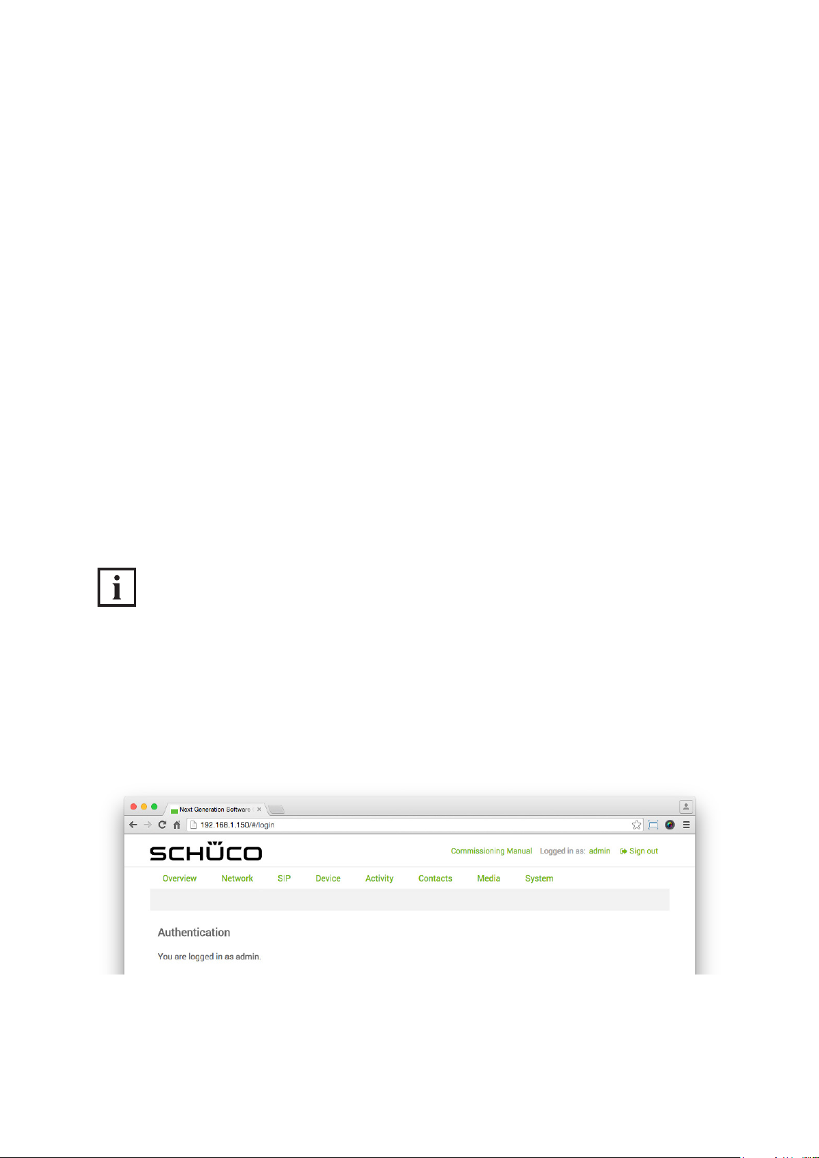
If the web interface has been called up, it already shows the most important information about the
DCS Touch Display on the „Overview“ page.
The following information is available in the „Device information“ section:
● Application: The name of the intercom station is shown here („SIP station“).
● Schüco FW version: The ofcial software version of the DCS Touch Display is shown here.
● Image version: The image of the ofcial software version of the DCS Touch Display is shown here.
● Device type: The type of intercom station is shown here („DCS Touch Display“).
● Status: The current operating mode of the intercom station is shown here.
● Locale: The current settings for language and country are shown here.
9.3. Logging in
You must log in to the web interface in order to make changes to the DCS Touch Display.
The „Login“ page appears when you click on „log in“ in the top right-hand corner of the window.
To return to the „Overview“ page, click on „Overview“ or on the Schüco logo on the left in
the web interface.
The standard administrator access data for the web interface is:
Username: admin
Password: schueco
INFORMATION
Access data
Contact your system administrator if the administrator access data has been changed or you have
been issued personal access data.
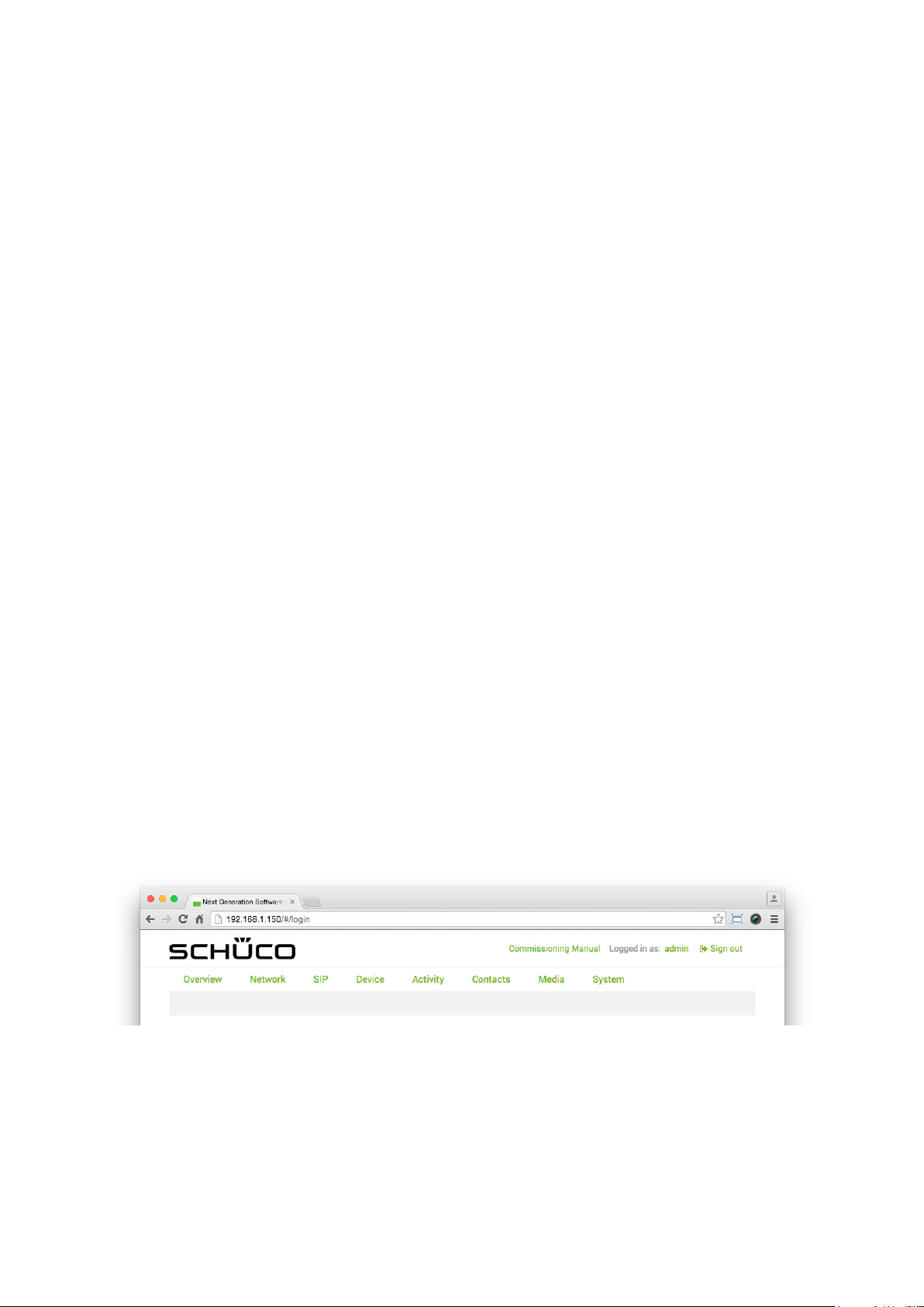
After successfully logging in as administrator, the message „You are logged in as administrator“
appears.
Dok-Nr.10000432116_01
Page 56
58
Schücode Commissioning instructions – Schüco DCS Touch Display
9.4. Conguration
The menu bar of the web interface is subdivided into the following sections in order to enable user-friendly and intuitive operation:
● Overview: View the most important data and settings.
● Network: Make IP network settings.
● SIP: Make SIP settings.
● Device
• Device: Make display settings for the screen.
• Audio: Make audio settings.
• Video: Make video streaming settings.
• Motion detection: Conguration of motion detection for the internal camera.
• Buttons: Make settings for the „Doorbell list“ view.
● Activity
• Activity: Make settings for the triggering of action sequences.
• Action sequences: Make settings for actions.
● Contacts: Manage contacts.
● Media
• Tones: Manage audio media.
• Photos: Manage image media.
● System
• System: Make system settings.
• User administration: Make settings for user accounts.
• Codes: Make settings for audio and video codes.
• Remote maintenance: Start remote maintenance for support purposes.
In addition, there are the following options above the menu bar:
● Schüco (company logo): Tapping here calls up the „Overview“ page (see „9.6 Overview“).
● Commissioning instructions: Tapping here calls up these instructions, which are stored on the
Schüco homepage.
● Logged in as: (user name): This shows which user is currently logged in. Clicking on the user name
(e.g. „admin“) immediately calls up the „User administration“ page, on which the prole can be edited (see „9.18.2 Prole“).
● Log out: By tapping here, the user currently logged in can log out.
Dok-Nr.10000432116_01
Page 57
Commissioning instructions – Schüco DCS Touch Display 59
Schüco de
INFORMATION
Action sequences and activities
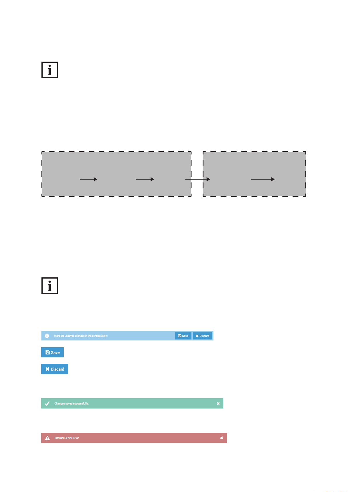
Action sequences and activities can be differentiated as follows: An action sequence allows a logical
command sequence to be dened, through which particular functions can be activated -
e.g. actuating a door opener (see „9.14 Action sequences“). An activity, on the other hand, allows a
trigger to be dened, which automatically performs an action sequence - e.g. in the event of an error
(see „9.13 Activity“).
Activity Action Sequence
Trigger
(e.g. input state change)
Device State
(e.g. “Idle”)
Activity
(detection of a
pre-dened
state change)
Action Sequence
(initiating a sequence)
Action
(e.g. switching
of an output)
9.5. Message boxes
The web interface displays message boxes in the form of change notices, conrmation messages or
error messages in the bottom part of the browser.
As soon as a conguration shows changes, a message box appears with a change notice.
INFORMATION
Applying changes
Changes are not saved automatically. The DCS Touch Display only applies the settings made
once the „Save“ button is clicked.
Click on this button to apply all changes.
Click on this button to discard all changes.
Once a change has been successfully saved, a message box with a conrmation message appears
(e.g. changes successfully saved or picture uploaded).
As soon as an error has been detected, a message box with an error message appears
(e.g. connection errors, incorrect conguration or server errors).
Dok-Nr.10000432116_01
Page 58

60
Schücode Commissioning instructions – Schüco DCS Touch Display
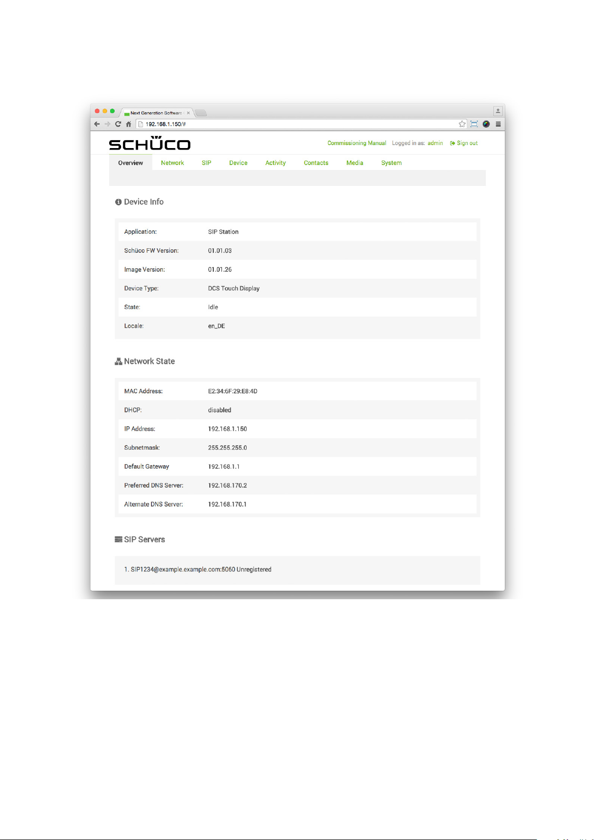
9.6. Overview when logged in
The most important information about hardware and software is displayed on the „Overview“ page.
All details on this page are for information purposes only and cannot be amended.
The following information is available in the „Device information“ section:
● Application: Displays name of the intercom station („SIP station“).
● Schüco FW version: Displays the ofcial software version of the DCS Touch Display.
● Image version: Displays the image of the ofcial software version of the DCS Touch Display.
● Version: The software version of the DCS Touch Display is shown.
● Device type: The type of intercom station is shown („DCS Touch Display“).
● Status: The current operating mode of the intercom station is shown.
● Locale: The current settings for language and country are shown.
The following information is available in the „Network status“ section:
● MAC address: The MAC address of the DCS Touch Display is shown.
● DHCP: This shows whether or not the DHCP function (automatic IP address assignment)
is activated.
● IP address: The IP address of the DCS Touch Display is shown.
● Subnet mask: The subnet mask of the DCS Touch Display is shown.
● Default gateway: The IP address of the default gateway for the router is shown.
● Preferred DNS server: The IP address of the primary DNS server is shown.
● Alternative DNS server: The IP address of the secondary DNS server is shown.
The following information is available in the „SIP server“ section:
Here you are shown how many SIP servers have been created and whether a connection to these
exists.
Dok-Nr.10000432116_01
Page 59
Commissioning instructions – Schüco DCS Touch Display 61
Schüco de
Dok-Nr.10000432116_01
Page 60
62
Schücode Commissioning instructions – Schüco DCS Touch Display
9.7. Network
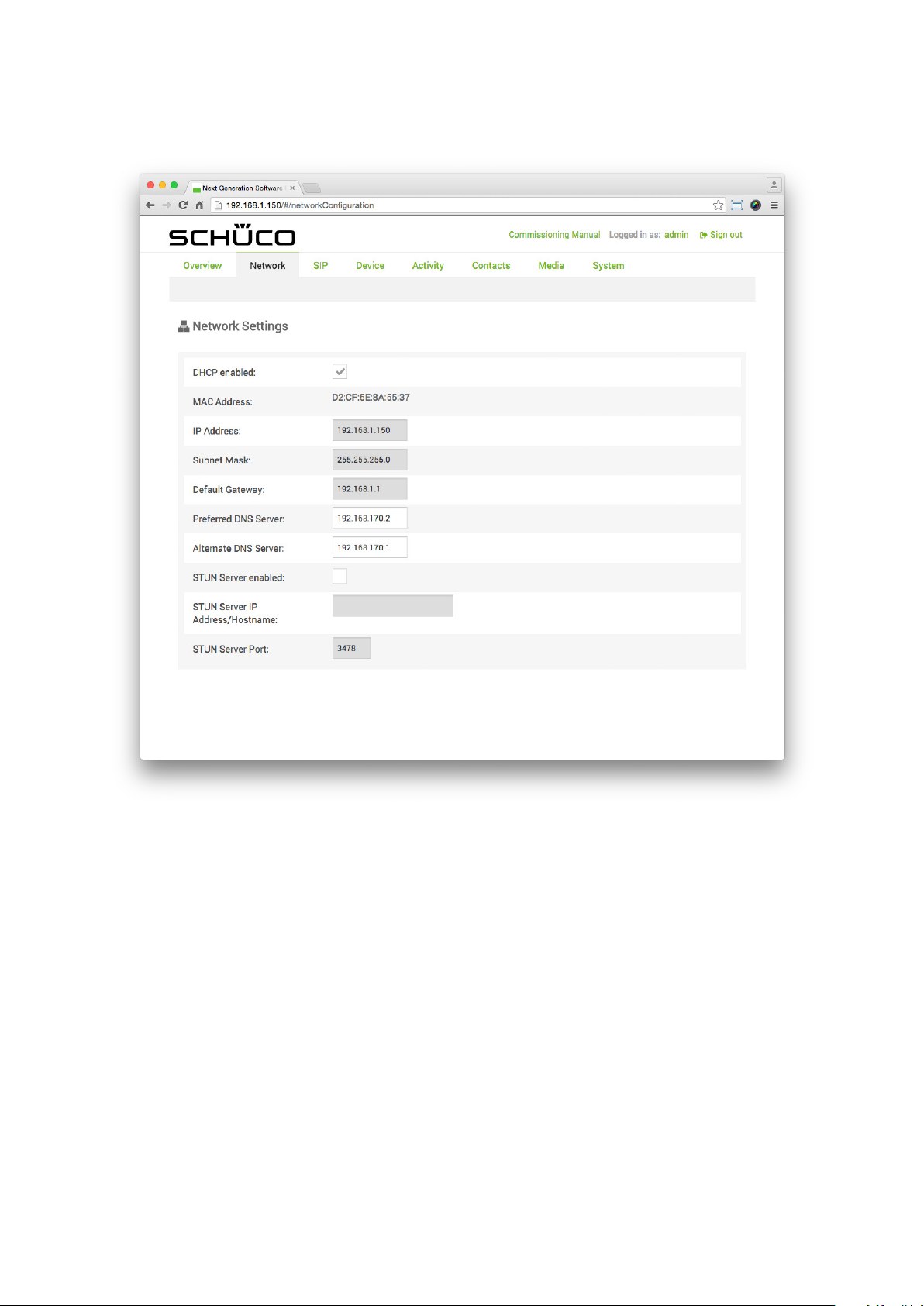
On the „Network“ page, it is possible to make all relevant settings in order to integrate the DCS Touch
Display into the building‘s existing network.
The following options are available in the „Network settings“ section:
● DHCP activated: Check this checkbox to automatically request the necessary IP settings from the
DHCP server. While this checkbox is checked, settings in the elds „IP address“, „Subnet mask“,
„Default gateway“, „Preferred DNS server“ and „Alternative DNS server are ignored.
● MAC address: The MAC address of the DCS Touch Display is shown here (cannot be changed).
● IP address: Enter the IP address of the DCS Touch Display (is only needed when the
„DHCP activated“ checkbox is unchecked).
● Subnet mask: Enter the network mask which belongs to the IP address
(is only needed when the „DHCP activated“ checkbox is unchecked).
● Default gateway: Enter the IP address of the router or default gateway
(is only needed when the „DHCP activated“ checkbox is unchecked).
● Preferred DNS server: Enter the IP address of the primary DNS server
(is only needed when the „DHCP activated“ checkbox is unchecked).
● Alternative DNS server: If necessary, enter a second IP address for the secondary DNS server (is
only needed when the „DHCP activated“ checkbox has been unchecked and an IP address has
been entered in the eld „Preferred DNS server“).
● STUN server activated: Check this checkbox to activate the STUN function
(Session Traversal Utilities for NAT).
● STUN server IP address/host name: Enter the IP address or the host name of the STUN server.
● STUN server port: Enter the port number for the address entered in the
„STUN server IP address/host name“ eld.
INFORMATION
Changes to the IP address
In the event of a change to the IP address of the DCS Touch Display, the web interface must be called
up again with the new IP address. Therefore, if necessary make a note of the new address before
saving to enable you to call up the web interface again.
What is STUN?
„Session Traversal Utilities for NAT“ is a network protocol, which detects rewalls and penetrates
NAT routers. With the aid of this protocol, SIP devices, amongst others, can receive data from
the internet within a building‘s network without any complications.
Dok-Nr.10000432116_01
Page 61
Commissioning instructions – Schüco DCS Touch Display 63
Schüco de
Dok-Nr.10000432116_01
Page 62
64
Schücode Commissioning instructions – Schüco DCS Touch Display
9.8. SIP
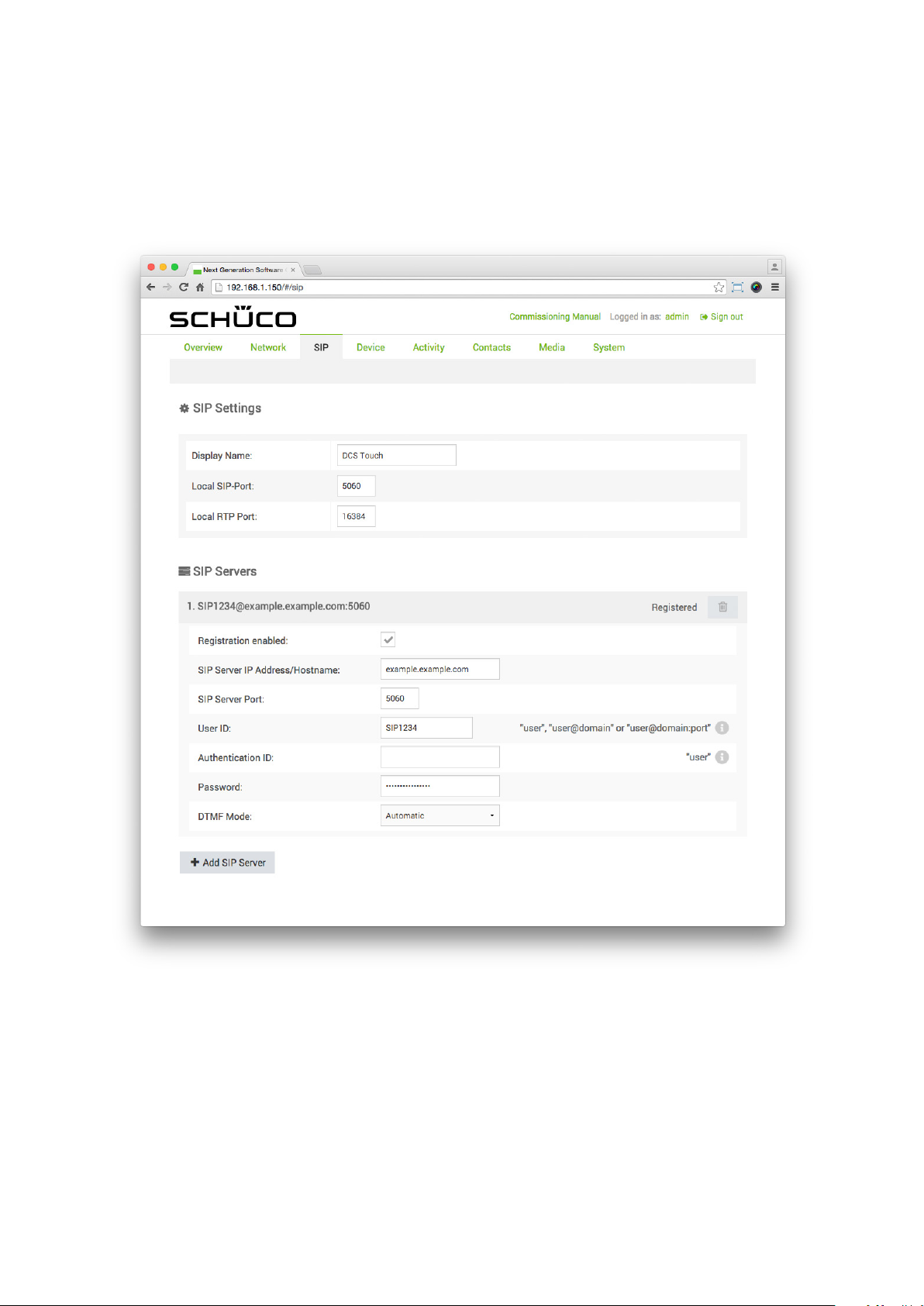
On the „SIP“ page, it is possible to make all relevant settings in order to connect the DCS Touch Display to an SIP server.
9.8.1. SIP settings
In the „SIP settings“ section, settings can be made which allow the Touch Display to communicate via
SIP (Session Initiation Protocol).
The following options are available in the „SIP settings“ section:
● Display name: If necessary, enter text for the SIP device (caller ID).
● Local SIP port: Enter the port number for the SIP protocol („5060“ as standard).
● Local RTP port: Enter the port number for the RTP protocol („16384“ as standard).
Dok-Nr.10000432116_01
Page 63
Commissioning instructions – Schüco DCS Touch Display 65
Schüco de
9.8.2. SIP server
In the „SIP server“ section, settings can be made which enable a connection between the DCS Touch
Display and an SIP server.
The following options are available in the „SIP server“ section:
● Registration activated: Check this checkbox to enable the registration of the SIP device with the
corresponding access data to an SIP server. For serverless operation, this checkbox must be
unchecked.
● SIP server IP/host name: Enter the IP or host address of the SIP server.
● SIP server port: Enter the port number for the address entered in the „SIP server IP/host name“
eld.
● User ID: Enter the telephone number of the SIP account for registration at the SIP server.
For some SIP servers, it is necessary to enter the domain in addition (e.g. „user_name@domain“).
● Authentication ID: Enter the authentication ID for the SIP device. This ID is only needed for certain
SIP servers.
● Password: Enter the password of the SIP account for registration at the SIP server.
● DTMF mode: Click on the „DTMF mode“ selection list. Here the following options are available
to you:
• Automatic: The SIP device adjusts the signal transmission automatically.
• RTP event (RFC2833): Signals are transmitted in accordance with protocol RFC 2833.
• SIP information: Signals are transmitted in accordance with the SIP protocol.
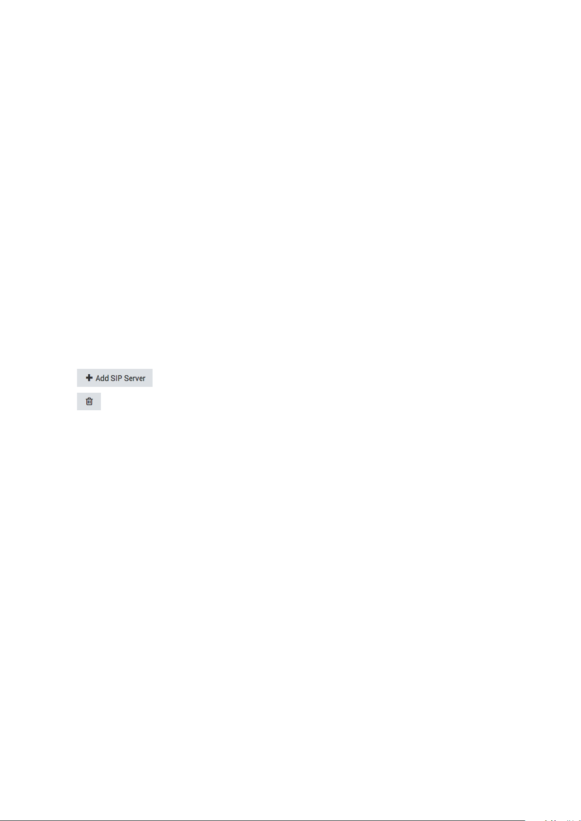
● : Click on this button to create up to two further SIP server settings areas.
● : Click on this button to delete the current SIP server settings area.
Dok-Nr.10000432116_01
Page 64
66
Schücode Commissioning instructions – Schüco DCS Touch Display
9.8.3. SIP connection
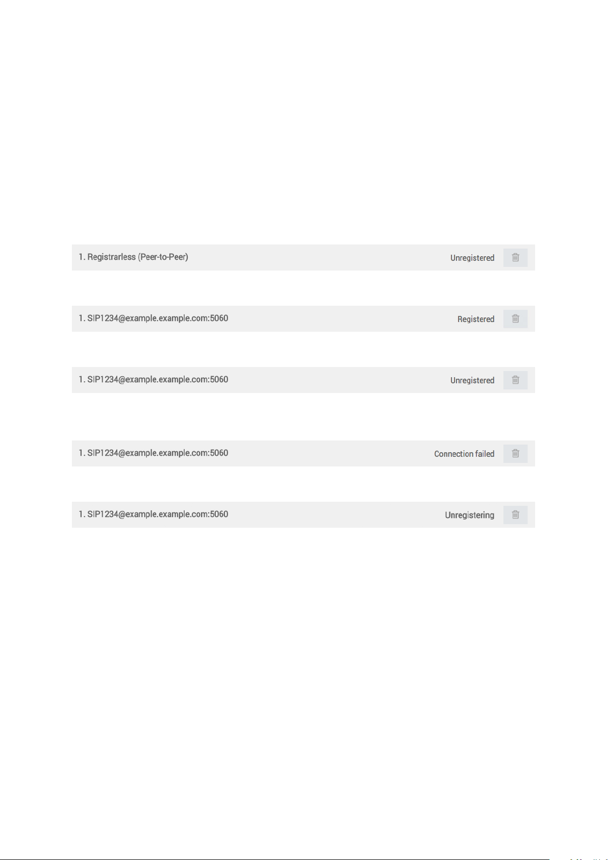
On the right-hand side of the header in the respective SIP server settings area, you are shown whether there is a connection to the respective SIP server.
The following display options are available:
● No registrar (Peer-to-Peer): The DCS Touch Display is working without a server.
● Registered: The DCS Touch Display is connected to an SIP server.
● Not registered: The DCS Touch Display is not connected to an SIP server.
● Connection failed: It was not possible to establish a connection between the DCS Touch Display
and the SIP server.
● Log off: The DCS Touch Display is logging off from the SIP server.
Dok-Nr.10000432116_01
Page 65
Commissioning instructions – Schüco DCS Touch Display 67
Schüco de
9.9. Device
9.9.1. Device
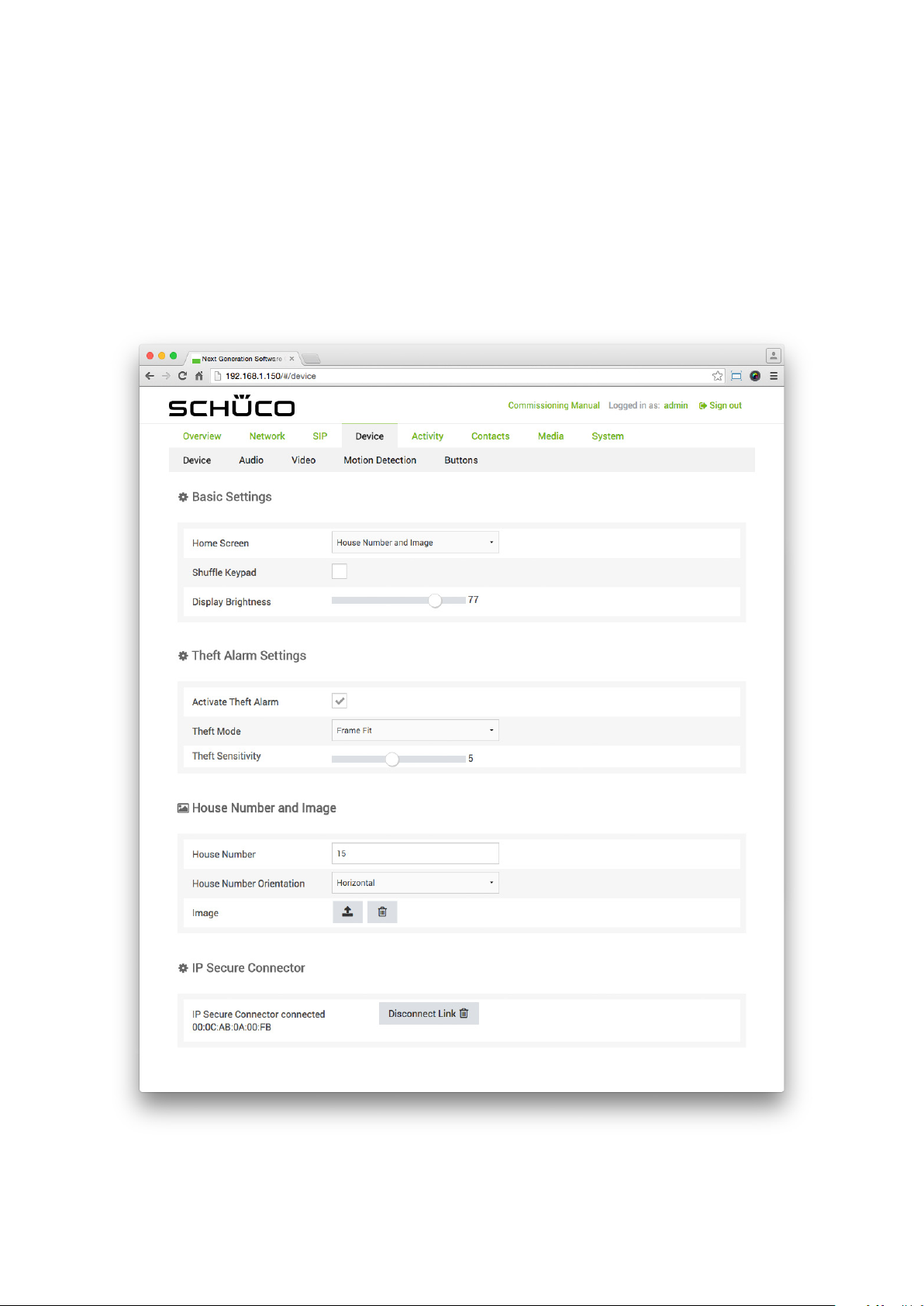
On the „Device“ page, it is possible to make display settings for the screen of the DCS Touch Display.
Dok-Nr.10000432116_01
Page 66
68
Schücode Commissioning instructions – Schüco DCS Touch Display
9.9.1.1 Basic settings
In the „Basic settings“ section, basic settings can be made for the screen of the DCS Touch Display.
The following options are available in the „Basic settings“ section:
● Start screen: In this selection list, choose which view you want the DCS Touch Display to show
in the device status „Idle“. The following options are available here:
• House number and image
• Contacts („Doorbell list“ view)
• Code entry
● Mix code entry buttons: Check this checkbox, if you want the digits in the „Code entry“ view to be
shown in a mixed, random order. If this checkbox is not checked, the digits are arranged in
the same way as a standard telephone keypad.
● Screen brightness: Use this control to adjust the brightness of the screen on the DCS Touch Display.
INFORMATION
Mixed code entry buttons
Code entry buttons that are reshufed each time the screen is called up make it harder to access
the „Conguration“ view or stored action sequences without authorisation, since the ngerprint
impressions left when the access code is entered are distributed evenly over the screen.
It is therefore impossible to reproduce the access code used with the aid of these impressions.
Dok-Nr.10000432116_01
Page 67

Commissioning instructions – Schüco DCS Touch Display 69
Schüco de
9.9.1.2 Anti-theft device
The anti-theft device can be activated and congured in the „Anti-theft device“ section.
INFORMATION
Deactivating the anti-theft device
It is essential that you observe the steps for deactivating the anti-theft device prior to removal,
as otherwise the alarm mode will be activated. If the DCS Touch Display is connected to an
IP secure connector in the alarm mode, the network connection and the PoE+ power supply between
the IP secure connector and the DCS Touch Display will be disconnected after 30 seconds when an
attempt is made to remove the DCS Touch Display incorrectly. In this way, any unauthorised access
from outside via this network cable is successfully prevented. To enable recommissioning of the
DCS Touch Display, it must be put back in its original position and the „PAIRING“ button pressed on
the IP secure connector. If necessary, the anti-theft device must be reactivated, as this function is
deactivated in the alarm mode.
Activating the anti-theft device
The inclination sensor calibrates itself once the anti-theft device is activated. To avoid the
DCS Touch Display switching to the alarm mode during installation, the anti-theft device should not be
activated until the DCS Touch Display is installed in a xed position.
The following options are available in the „Anti-theft device“ section:
● Activating the anti-theft device: Check this checkbox to activate the anti-theft device.
● Mode: In this selection list, select the installation position of the DCS Touch Display.
Here the following options are available:
• Door installation: If the DCS Touch Display is installed in a door, this option must be selected to
prevent the anti-theft device from activating the alarm mode by mistake due to the movements of
the door when opening and closing.
• Frame installation: If the DCS Touch Display is installed in a DCS unit, a slight tilt angle is
enough to activate the alarm mode (activated as standard).
● Sensitivity: Use this control to adjust the sensitivity to a value between „1“ and „10“ at which
the alarm mode should be activated („5“ as standard).
Dok-Nr.10000432116_01
Page 68
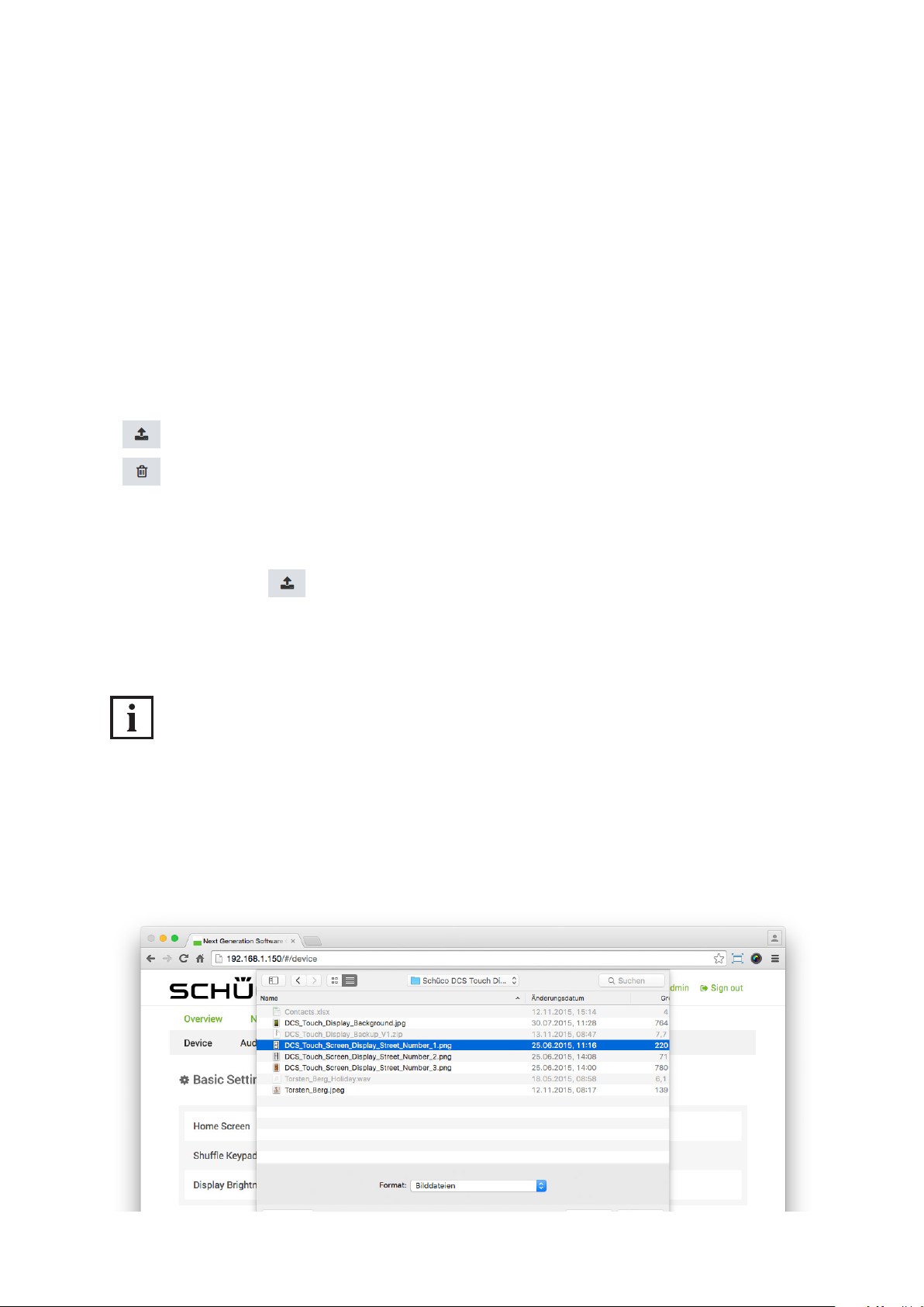
70
Schücode Commissioning instructions – Schüco DCS Touch Display
9.9.1.3 House number and image
In the „House number and image“ section, you can determine what is to be displayed in the „House
number/image“ view.
The following options are available in the „House number and image“ section:
● House number: Enter a house number in this eld. In principle, a larger amount of text can also
be entered in this eld. However, this is scaled due to the size of the screen and is no longer legible
under some circumstances.
● Alignment of the house number: In this selection list, choose how you want the text in the
„House number“ eld to be aligned. Here the following options are available:
• Horizontal: The text is aligned horizontally.
• Vertical: The text is aligned vertically.
● : Click on this button to upload an image.
● : Click on this button to delete an image that has already been uploaded.
Proceed as follows to upload an image:
1. Click on the button .
2. Select the desired image and click on the „Open“ button.
3. Check whether the correct image has been uploaded and click on the „Save“ button.
INFORMATION
Image properties
To avoid black borders at the top and bottom or at the sides, only images of size 480 x 800 pixels
(or a corresponding ratio) should be uploaded. The DCS Touch Display only supports images in
the le formats JPG and PNG. The maximum le size is 6 MB.
Dok-Nr.10000432116_01
Page 69
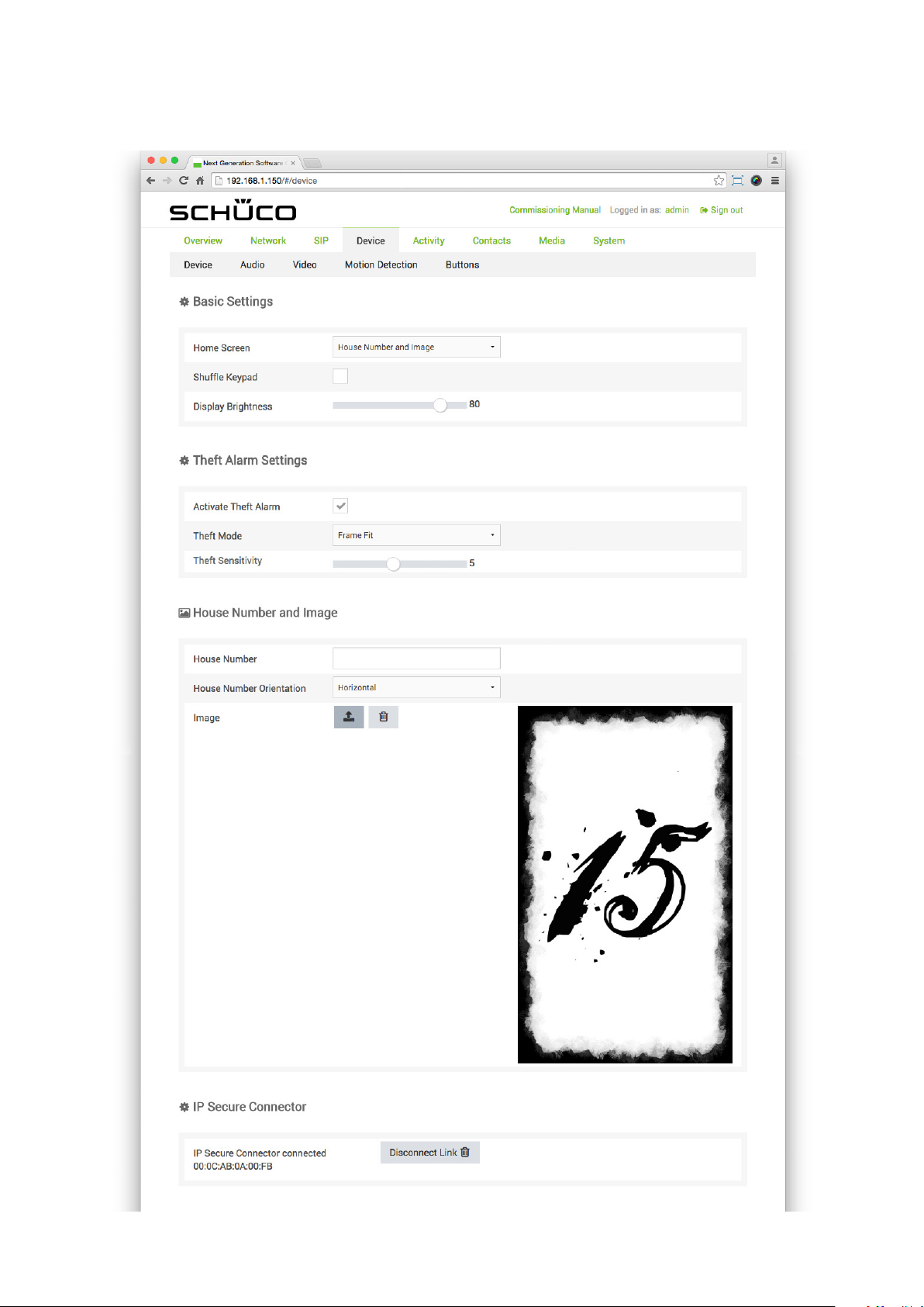
Commissioning instructions – Schüco DCS Touch Display 71
Schüco de
Dok-Nr.10000432116_01
Page 70
72
Schücode Commissioning instructions – Schüco DCS Touch Display
9.9.1.4 IP secure connector
In order to connect the DCS Touch Display to an associated IP secure connector, it is necessary
to search for an IP secure connector and to connect it. If no IP secure connector is provided for
the installation, you can skip this point.
The following option is available in the „IP secure connector“ section:
: Click on this button to search for an IP secure connector in the network and connect
it to the DCS Touch Display. Note that the „PAIRING“ button on the IP secure connector must be
pressed for a successful connection.
: Click on this button to disconnect the connection between an IP secure connector
and the DCS Touch Display.
INFORMATION
More information
More detailed information on the connection of the IP secure connector can be found in the
installation instructions.
Dok-Nr.10000432116_01
Page 71
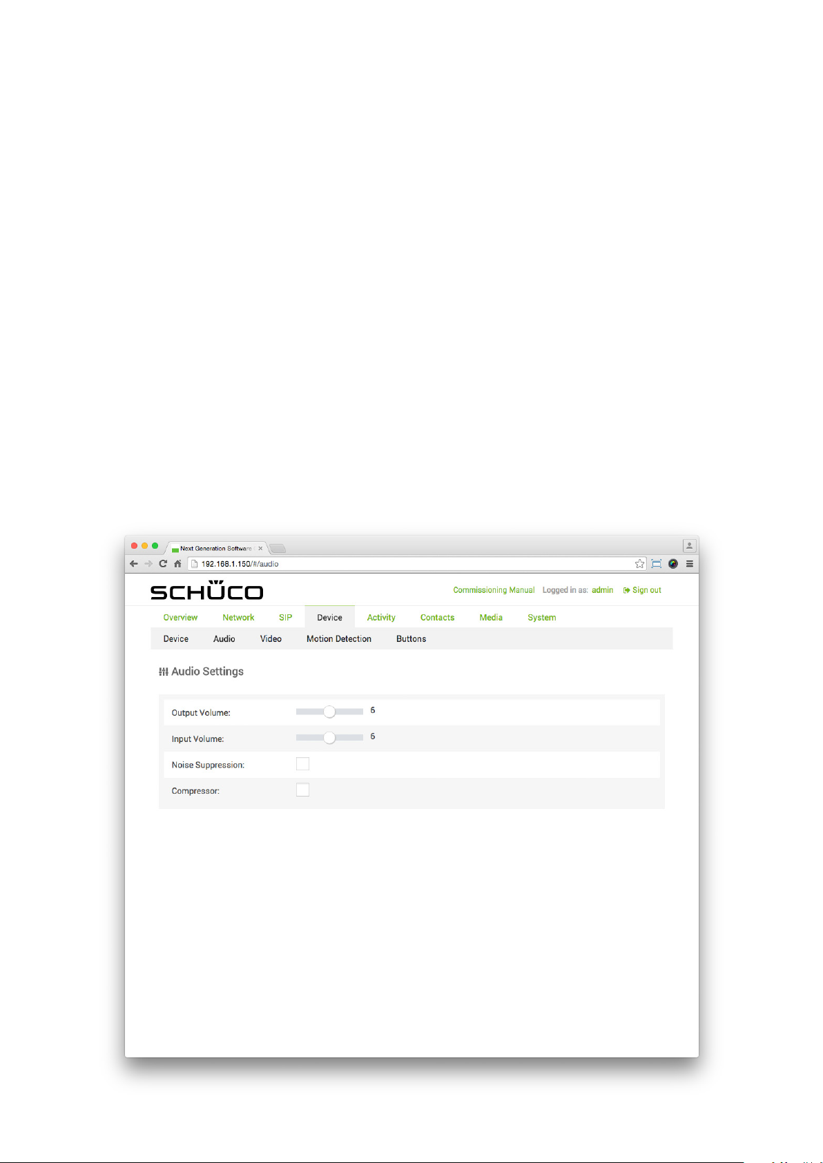
Commissioning instructions – Schüco DCS Touch Display 73
9.9.2. Audio
On the „Audio“ page, it is possible to make basic audio settings.
The following options are available in the „Audio settings“ section:
● Output volume: Adjust the output volume of the loudspeaker on the DCS Touch Display
between „0“ and „12“. Microphone volume: Adjust the sensitivity of the microphone Output volume:
Adjust the output volume of the loudspeaker on the DCS Touch Display between „0“ and „12“.
● Microphone volume: Adjust the sensitivity of the microphone for the DCS Touch Display
between „0“ and „12“.
● Noise suppression: Check this checkbox to activate the noise suppression
(deactivated as standard).
● Compressor: Check this checkbox to activate the automatic level adjustment, whereby quiet input
signals (e.g. from a telephone or an intercom station) are increased in volume
(deactivated as standard).for the DCS Touch Display between „0“ and „12“.
● Noise suppression: Check this checkbox to activate the noise suppression
(deactivated as standard).
● Compressor: Check this checkbox to activate the automatic level adjustment, whereby quiet input
signals (e.g. from a telephone or an intercom station) are increased in volume
(deactivated as standard).
Schüco de
Dok-Nr.10000432116_01
Page 72
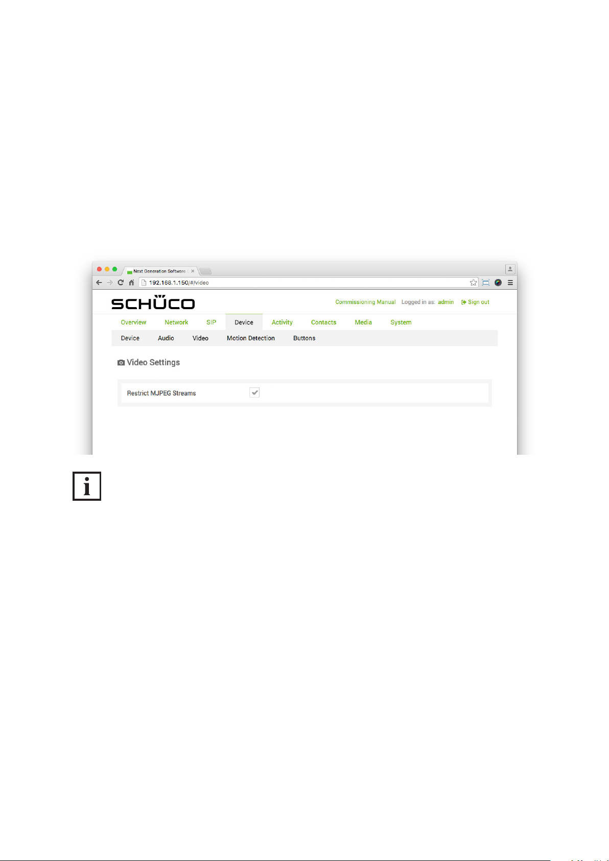
74
Schücode Commissioning instructions – Schüco DCS Touch Display
9.9.3. Video
On the „Video“ page, it is possible to make basic video streaming settings.
The following option is available in the „Video settings“ section.
● Limit MJPEG streams: Check this checkbox to allow video streaming only during video
conversations between the DCS Touch Display and the telephone/intercom station.
This prevents any unauthorised access to the camera image on the DCS Touch Display via
the computer within the network (activated as standard).
INFORMATION
Video streaming
When the checkbox „Limit MJPEG streams“ is unchecked, up to six video streaming calls can be
made via the computer within one network. For this, the IP address with „/mjpeg/video.mjpg“ added
to the end must be entered in the address bar of the browser. (e.g. „http://192.168.1.150/mjpeg/video.
mjpg“). If the checkbox is checked, it is only possible to make a call using video streaming via a computer within a network if the DCS Touch Display is „Ringing“ or call without video is congured.
The video stream is shown in the browser in the format 480 x 640 pixels.
Dok-Nr.10000432116_01
Page 73
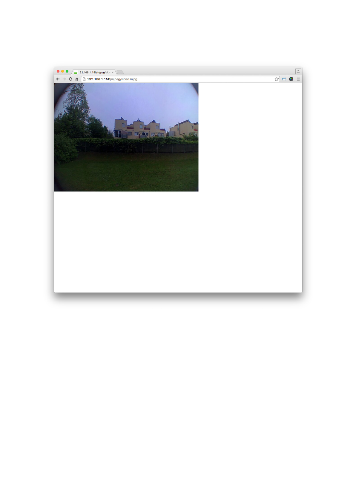
Commissioning instructions – Schüco DCS Touch Display 75
Schüco de
Dok-Nr.10000432116_01
Page 74
76
Schücode Commissioning instructions – Schüco DCS Touch Display
9.9.4. Motion detection
On the „Motion detection“ page, it is possible to determine the area of the camera image which is to
be sensitised when the motion detection is activated.
The following options are available on the „Motion detection“ page:
● Sensitivity: Use this control to adjust the sensitivity of the motion detection of the camera on the
DCS Touch Display.
● : Click on this button to activate the complete video image for motion detection.
● : Click on this button to deactivate the complete video image for motion detection.
The video image on the „Motion detection“ page is shown in real time. Here there is a grid of
12 x 16 boxes, which can all be activated individually for motion detection.
There are two options for the boxes:
● Normal brightness and green border: The box or the area is activated for motion detection.
● Darkened and no border: The box or the area is deactivated for motion detection.
INFORMATION
Activating boxes for motion detection
For best results, only activate boxes in the area of the video image in which a movement can only
be detected when a person approaches the DCS Touch Display. If necessary, deactivate boxes in the
area of the video image in which a road, trees or other movements that are undesirable for motion
detection may be detected.
Proceed as follows to activate boxes for motion detection:
1. Click on .
2. Click on the boxes that you want to activate. Alternatively, you can also use the cursor to select
an area in which you want to activate boxes.
Dok-Nr.10000432116_01
Page 75
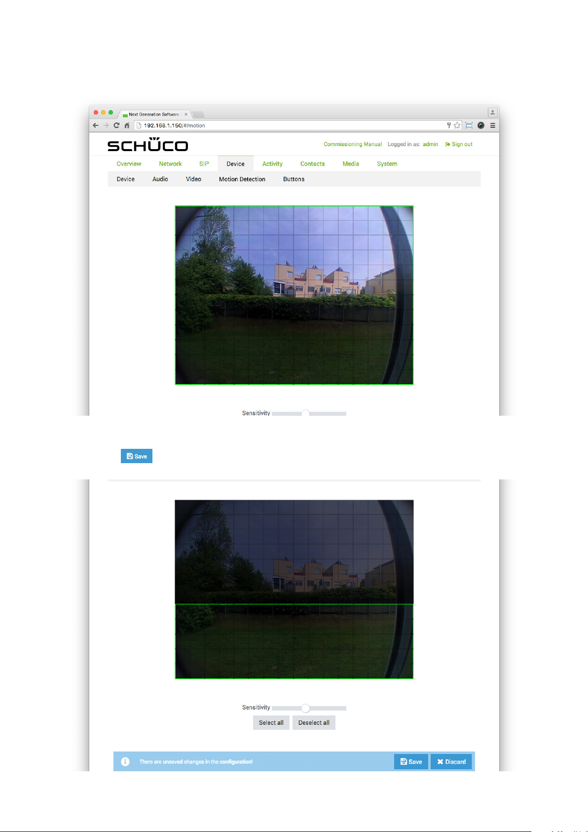
Commissioning instructions – Schüco DCS Touch Display 77
Schüco de
3. Adjust the sensitivity of the motion detection via the „Sensitivity“ control.
4. Click on .
Dok-Nr.10000432116_01
Page 76
78
Schücode Commissioning instructions – Schüco DCS Touch Display
9.9.5. Buttons
On the „Buttons“ page, it is possible to make settings for the „Doorbell list“ view to enable you to
initiate a call to a contact or start an action sequence, for example.
INFORMATION
Doorbell list
If no buttons have been congured on the „Buttons“ page, it is only possible to switch between
the „Start screen“ and „Code entry“ views on the DCS Touch Display screen before entering
the access code (the „Doorbell list“ is not displayed).
The following options are available in the „Buttons“ section:
● : Click on this button to sort the buttons (contacts) by rst name.
• : If the arrow is pointing upwards, the buttons are sorted alphabetically in ascending order.
• : If the arrow is pointing downwards, the buttons are sorted alphabetically in
descending order.
● : Click on this button to sort the buttons (contacts) by surname.
• : If the arrow is pointing upwards, the buttons are sorted alphabetically in ascending order.
• : If the arrow is pointing downwards, the buttons are sorted alphabetically in descending
order..
● : Click on this button to add a new button.
● : Click on this button to delete the desired button.
● First name: Enter the rst name of the contact in this eld. When selecting a contact, it is also
possible to copy over this line of text automatically.
● Surname: Enter the surname of the contact in this eld. When selecting a contact, it is also possible
to copy over this line of text automatically.
● Company mode: Check this checkbox to have the contact or action sequence displayed in
company mode. Here the elds „First name“ and „Surname“ are not displayed on the screen
of the DCS Touch Display and the prole picture (e.g. company logo) is displayed in the centre.
• : Click on this button to upload a prole picture. When selecting a contact, it is also possible
to copy over the corresponding prole picture automatically.
• : Click on this button to delete the corresponding prole picture.
• Action or action sequence: Select the desired action or action sequence.
The following options are available for this:
• Play audio le: Here an audio le is played which has already been uploaded via the „Media“
page.
• Output: Here an output (relay) on the DCS Touch Display („DCS Touch Display - OUT 1“ or
„DCS Touch Display - DC-OUT 2“) or IP secure connector („IP secure connector - OUT 1“,
„IP secure connector - OUT 2“ or „ IP secure connector - DC-OUT 3“) is switched.
• Send e-mail: Here an e-mail is sent from the contact which was congured on the „System“
page. End conversation: Here the current call is ended.
Dok-Nr.10000432116_01
Page 77
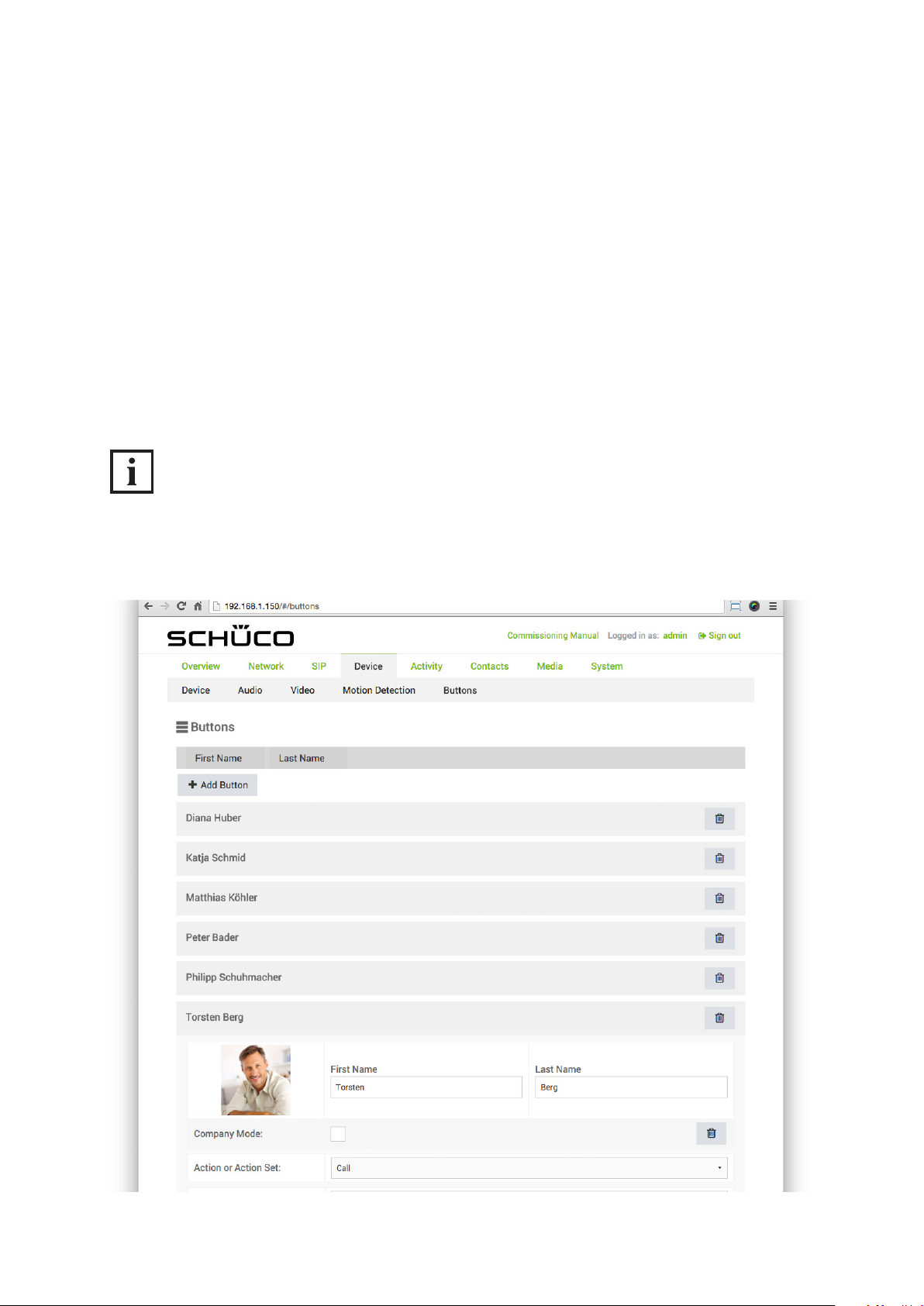
Commissioning instructions – Schüco DCS Touch Display 79
Schüco de
• Logout: Here the user currently logged in is logged out.
• Mute microphone: Here the microphone signal is muted.
• Call: Here a call is initiated to a contact which has already been created on the „Contacts“
page.
• Accept call: Here an incoming call is answered.
• Snapshot: Here a picture is taken using the built-in camera. This can be displayed on the „Me-
dia“ page. Send DTMF tone: Here a DTMF tone is sent to an SIP-compatible intercom station
or an SIP telephone.
• Play location report to counterpart intercom station: This option currently has no function.
• Delayed action: Here a specic action sequence is only started after a dened period of time
has elapsed.
• Switch video: This option currently has no function.
• Show view: Here the screen of the DCS Touch Display switches to a congurable view.
• Show symbol: Here a congurable symbol is shown on the screen of the DCS Touch Display.
INFORMATION
Action sequences
It is also possible to select an action sequence in the „Action or action sequence“ selection list which
was previously created on the „Action sequence“ page.
Dok-Nr.10000432116_01
Page 78
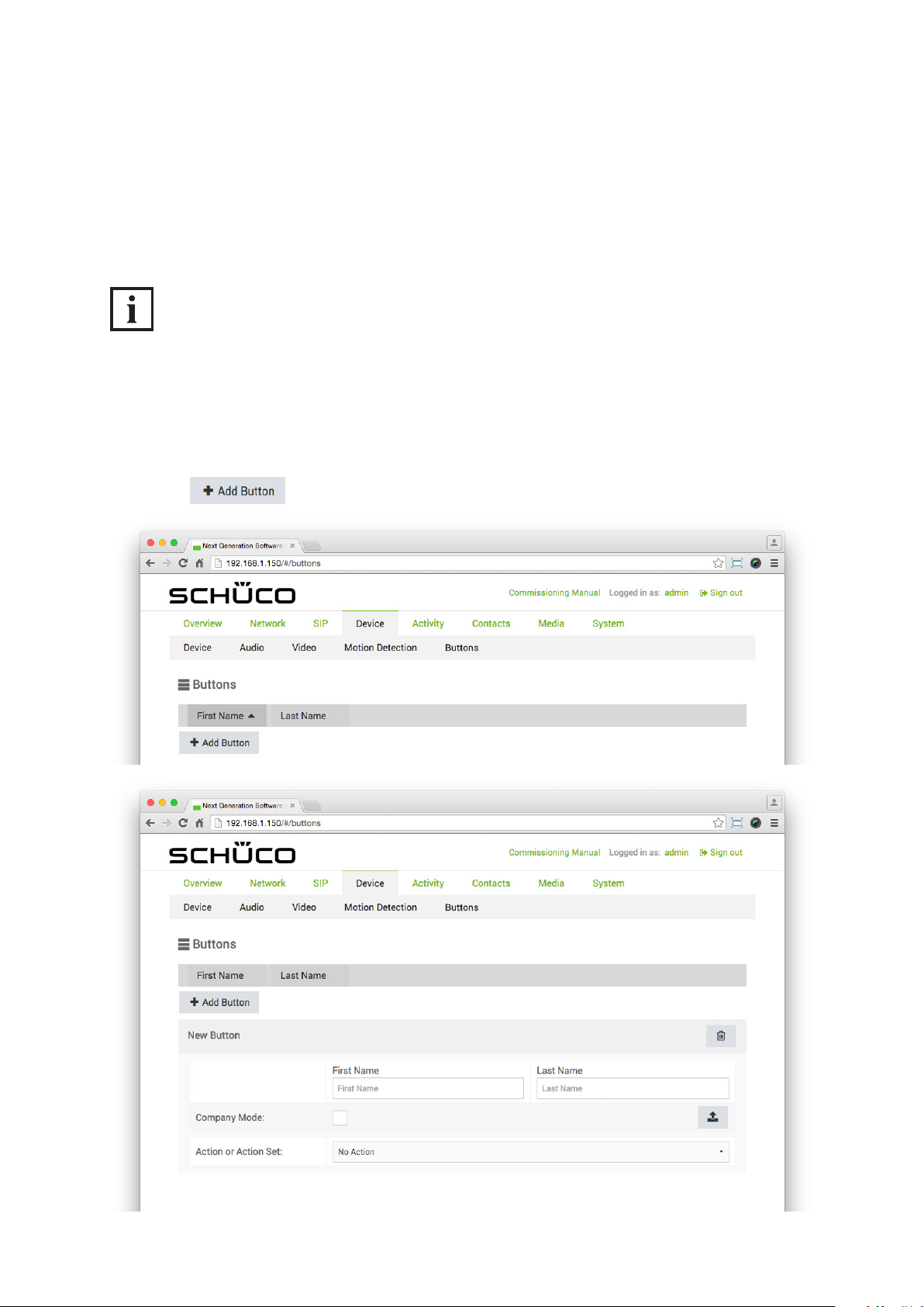
80
Schücode Commissioning instructions – Schüco DCS Touch Display
9.9.5.1 Adding a new contact to the doorbell list
Call destinations, which have been entered on the „Contacts“ page, are not displayed automatically
in the „Doorbell list“ view. Consequently it is possible to manage contacts without having to delete
them on the „Contacts“ page in the event that they are temporarily not used (e.g. during an absence).
In this example, you are shown how to add a contact in the „Doorbell list“ view.
INFORMATION
Contacts in the doorbell list
To be able to add contacts to the „Doorbell list“ view, it is a prerequisite that at least one contact has
been entered on the „Contacts“ page (see „9.15 Contacts“).
Proceed as follows to add a contact in the „Doorbell list“ view:
1. Click on . The „New button“ area appears.
Dok-Nr.10000432116_01
Page 79
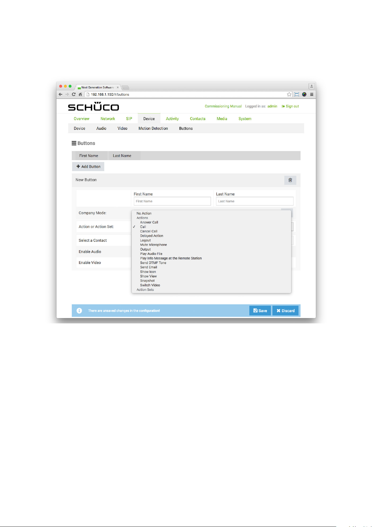
Commissioning instructions – Schüco DCS Touch Display 81
2. Wählen Sie in der Auswahlliste „Aktion oder Aktionssequenz“ die Option „Ruf“ aus.
Schüco de
Dok-Nr.10000432116_01
Page 80
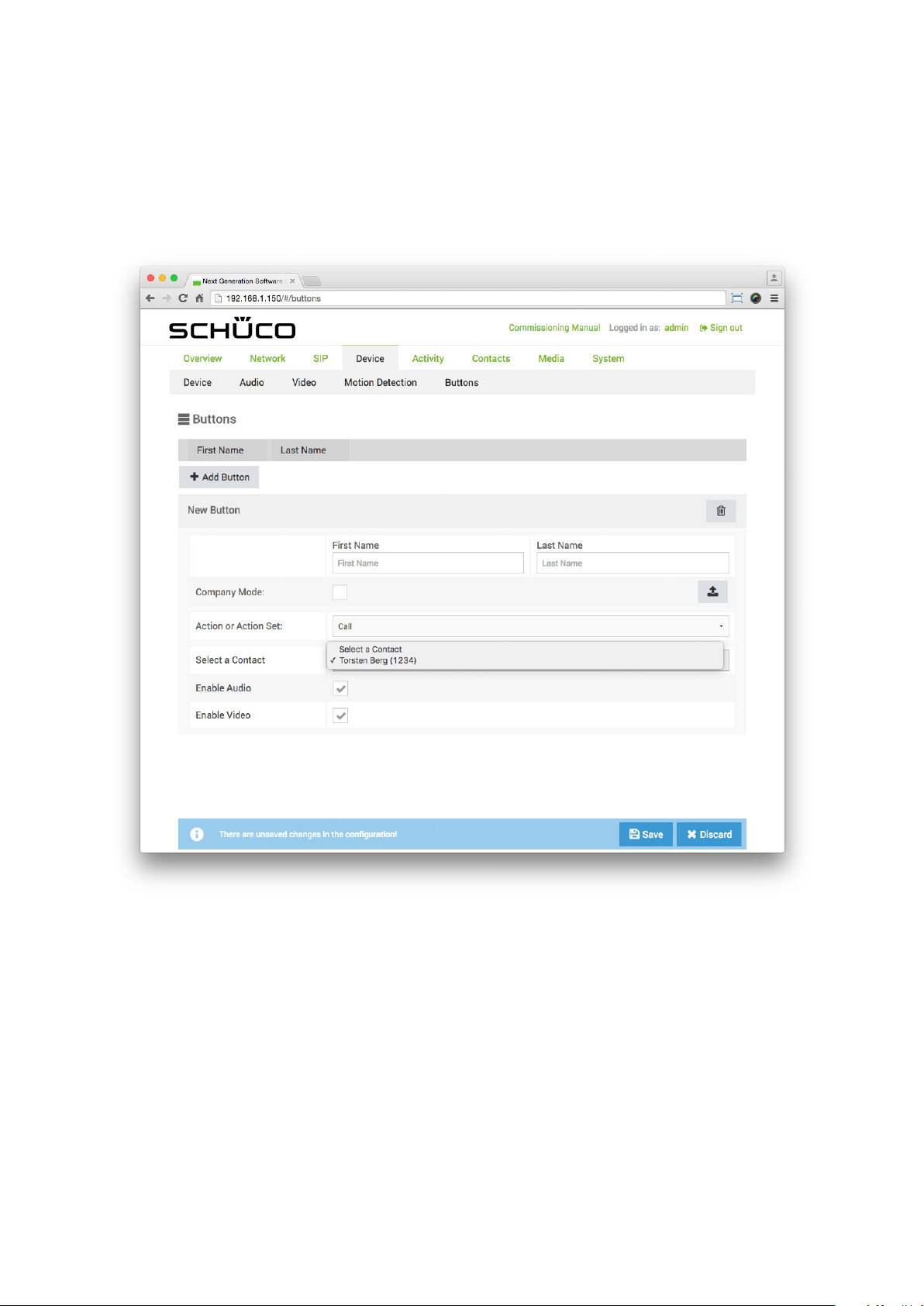
82
Schücode Commissioning instructions – Schüco DCS Touch Display
3. In the „Select contacts“ selection list, select the desired contact. The „Overwrite settings?“
dialog box appears.
Dok-Nr.10000432116_01
Page 81
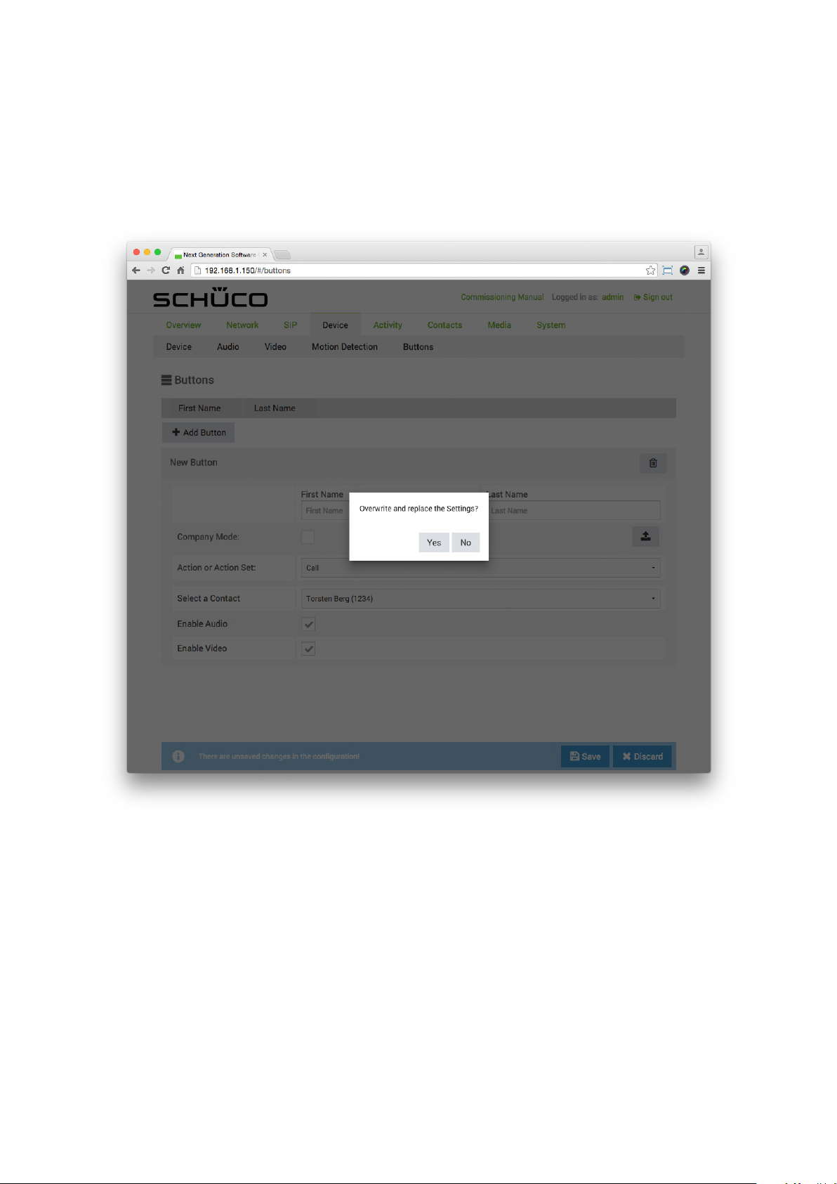
Commissioning instructions – Schüco DCS Touch Display 83
4. Click on „Yes“ to automatically copy over the elds „First name“ and „Surname“ as well as
the prole picture of the contact.
Schüco de
Dok-Nr.10000432116_01
Page 82
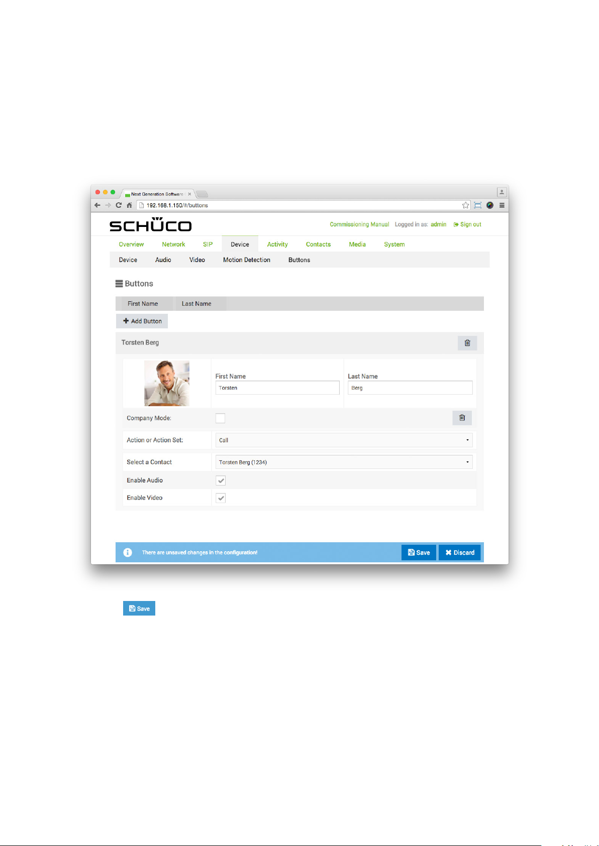
84
Schücode Commissioning instructions – Schüco DCS Touch Display
5. Ensure that the checkboxes „Activate audio“ and „Activate video“ are checked to enable audio
and images for a call. If you do not want to use video transmission, uncheck the „Activate video“
checkbox.
6. Click on .
Dok-Nr.10000432116_01
Page 83
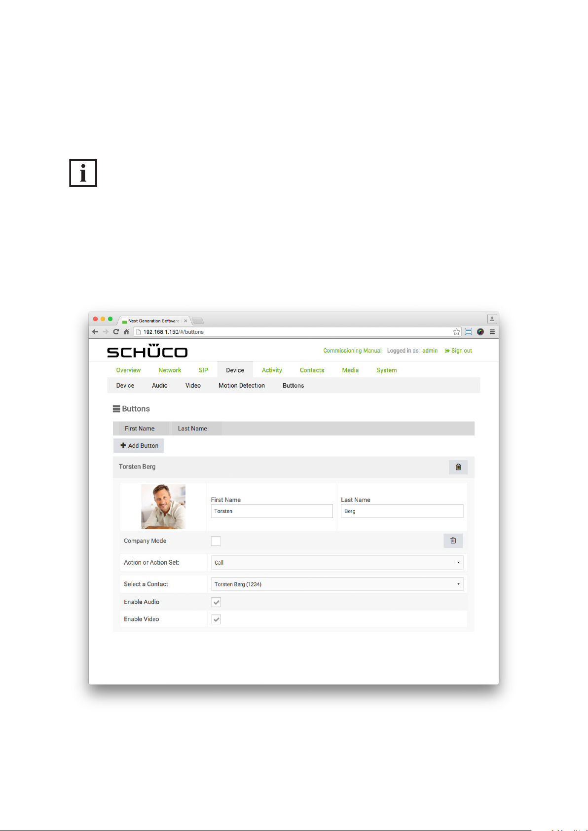
Commissioning instructions – Schüco DCS Touch Display 85
Schüco de
In the „Action or action sequences“ selection list, particular actions can be selected. The following
example will help to explain how an audio le previously uploaded on the „Media“ page can be played
when trying to call a contact using the DCS Touch Display. The aim here is to store an audio le for
a contact that has already been created which informs a visitor that the contact is currently on holiday.
INFORMATION
Uploading an audio le
More detailed information about uploading audio les can be found under „9.16.1 Adding
an audio le“.
To store an audio le for a contact, proceed as follows:
1. Click on the eld of the button already created to open the settings area.
Dok-Nr.10000432116_01
Page 84
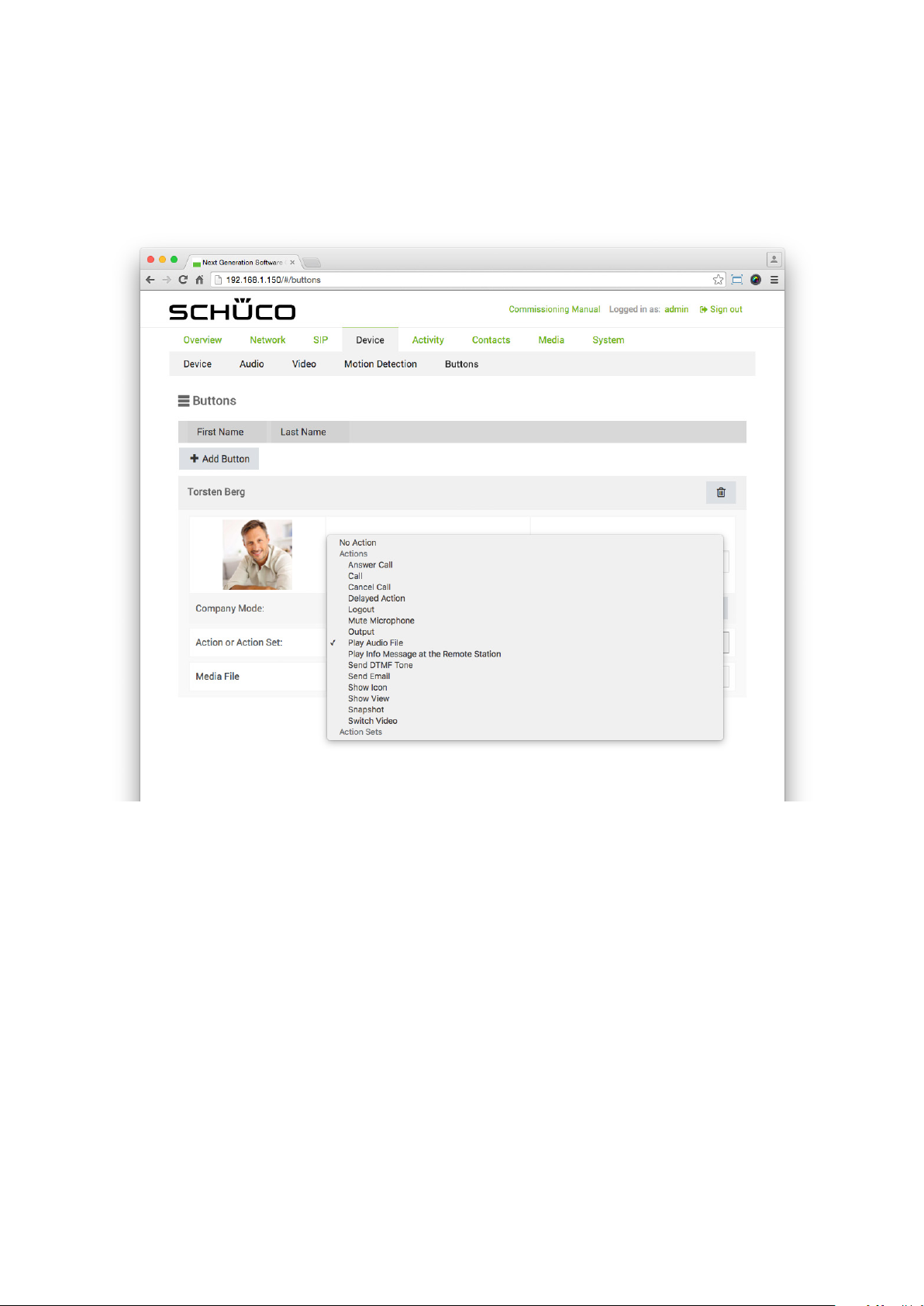
86
Schücode Commissioning instructions – Schüco DCS Touch Display
2. In the „Action or action sequence“ selection list, select the „Play audio le“ option.
Dok-Nr.10000432116_01
Page 85
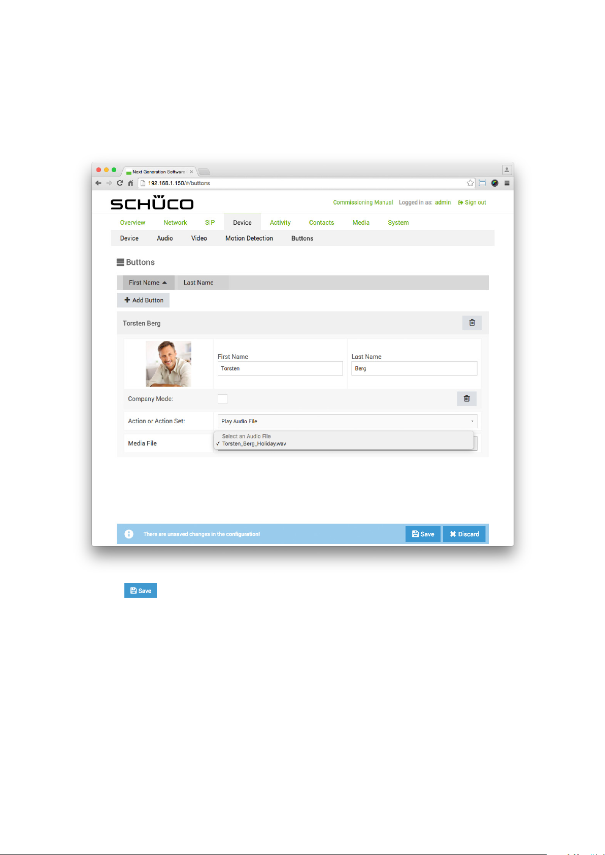
Commissioning instructions – Schüco DCS Touch Display 87
3. In the „Media le“ selection list, select the corresponding audio le option.
Schüco de
4. Click on .
Dok-Nr.10000432116_01
Page 86
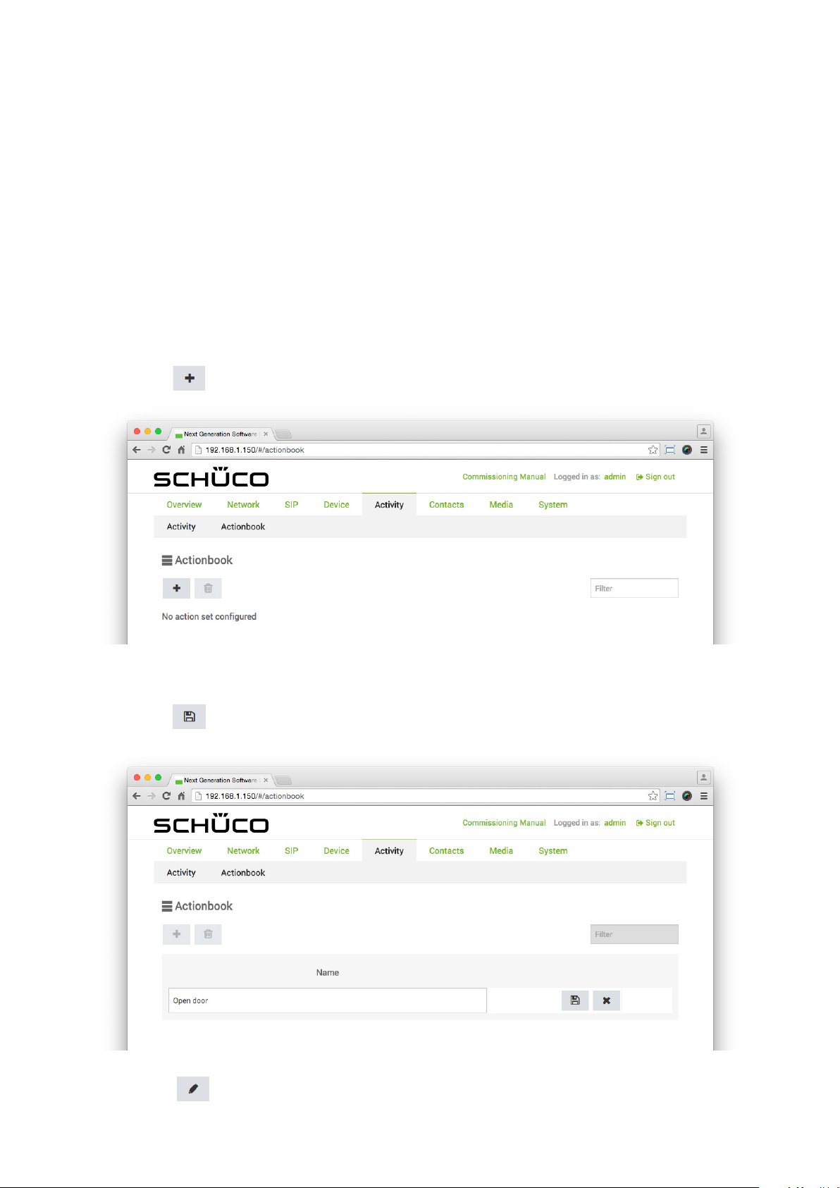
88
Schücode Commissioning instructions – Schüco DCS Touch Display
9.9.5.2 Adding an action sequence
On the „Buttons“ page, previously congured action sequences can be selected in the
„Action or action sequence“ selection list. The following example will help to explain how an
action sequence is created on the „Action sequences“ page and how this is then stored on the
„Buttons“ page with a new button. The aim here is to create a button for opening the entrance door
in the „Doorbell list“ view which only ever actuates the door opener between 9:00 and 18:00 from
Monday to Friday.
To create an action sequence for a door opener and store this with a new button, proceed as follows:
1. Open the „Action sequences“ page via „Activity“.
2. Click on .
3. Enter a meaningful term or phrase for the action sequence in the „Name“ eld (e.g. „Open door“).
4. Click on .
5. Click on . .
Dok-Nr.10000432116_01
Page 87
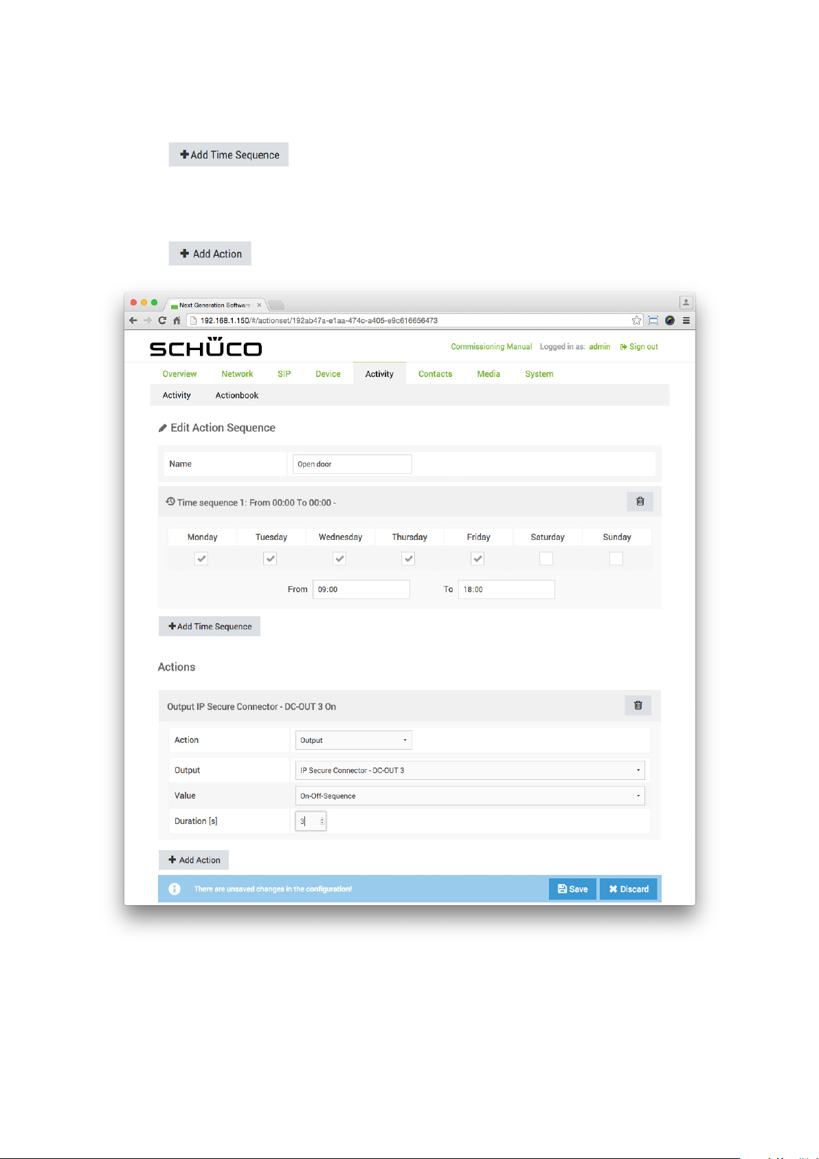
Commissioning instructions – Schüco DCS Touch Display 89
6. Click on .
7. Check the checkboxes for the days „Monday“ to „Friday“ and enter the time at which the
action sequence is to be available in the elds „From“ and „To“ (e.g. from „09:00“ to „18:00“).
8. Click on .
Schüco de
Dok-Nr.10000432116_01
Page 88
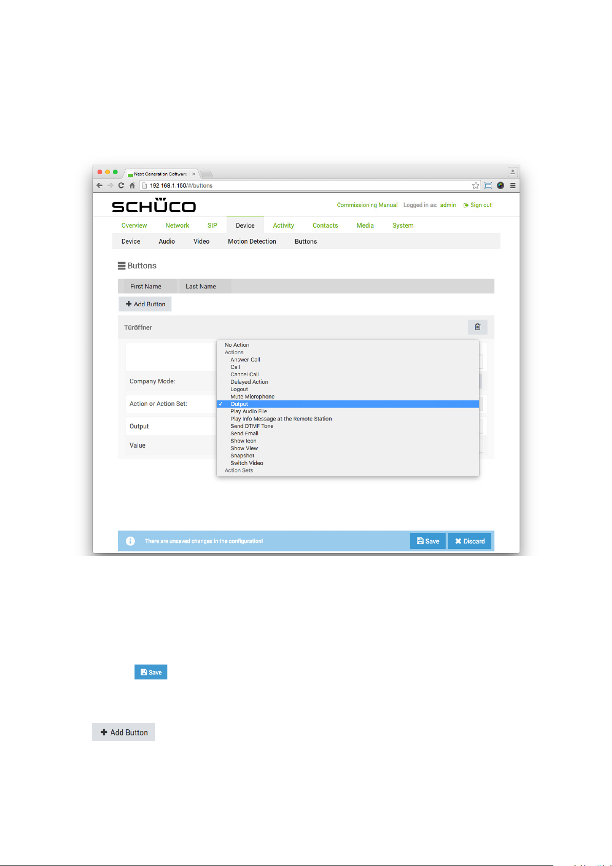
90
Schücode Commissioning instructions – Schüco DCS Touch Display
9. In the „Action“ selection list, select the „Output“ option.
10. In the „Output“ selection list, select the output to which the door opener is connected
(e.g. „DCS Touch Display - OUT1“).
11. In the „Value“ selection list, select the „On-off sequence“ option.
12. In the eld „Duration [s]“, enter the time in seconds for which the door opener is to be actuated
(e.g. „3“).
13. Click on . .
14. Open the „Buttons“ page via „Device“.
15. Click on . The „New button“ area appears.
16. Click on the newly created area to open it.
17. In the „First name“ eld, enter a meaningful name (e.g. „Door opener“). You can leave the
„Surname“ eld blank.
Dok-Nr.10000432116_01
Page 89
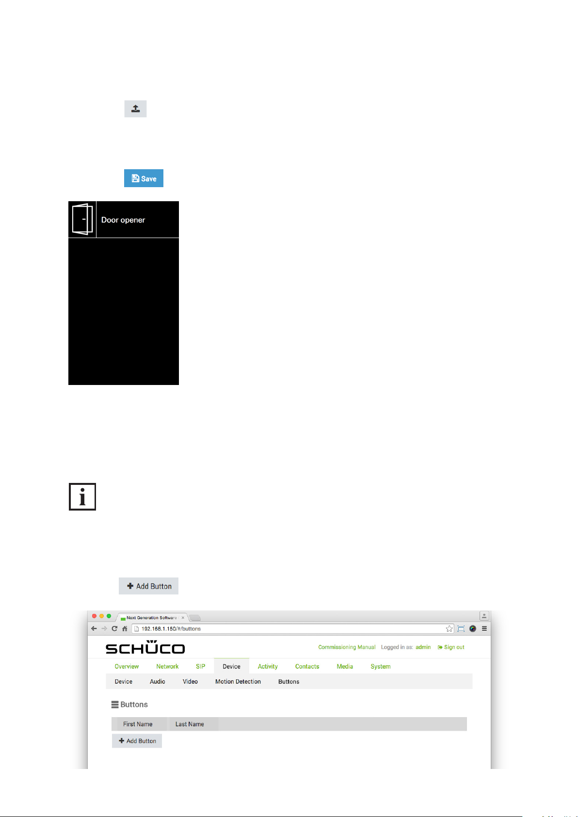
Commissioning instructions – Schüco DCS Touch Display 91
Schüco de
18. Click on and upload an appropriate image, if available.
19. In the „Action or action sequence“ selection list, select the action sequence previously created
(e.g. „Door opener“).
20. Click on .
9.9.5.3 Adding a contact in company mode
In company mode, contacts can be displayed „Doorbell view“ across the entire width without a name
and with only an image in the. In the following example, you are shown how to add a contact to
the „Doorbell list“ view in company mode.
INFORMATION
Contacts in the doorbell list
To be able to add a contact to the „Doorbell list“ view, at least one contact must be available on the
„Contacts“ page.
1. Click on . The „New button“ area appears.
Dok-Nr.10000432116_01
Page 90
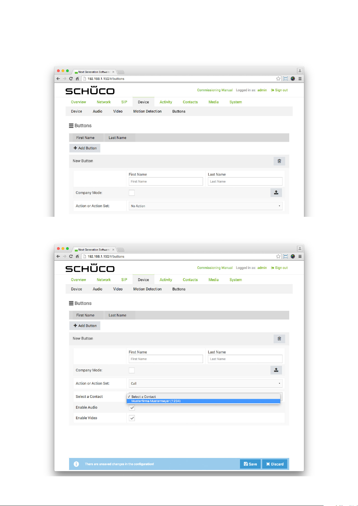
92
Schücode Commissioning instructions – Schüco DCS Touch Display
2. In the „Action or action sequence“ selection list, select the „Call“ option.
Dok-Nr.10000432116_01
Page 91
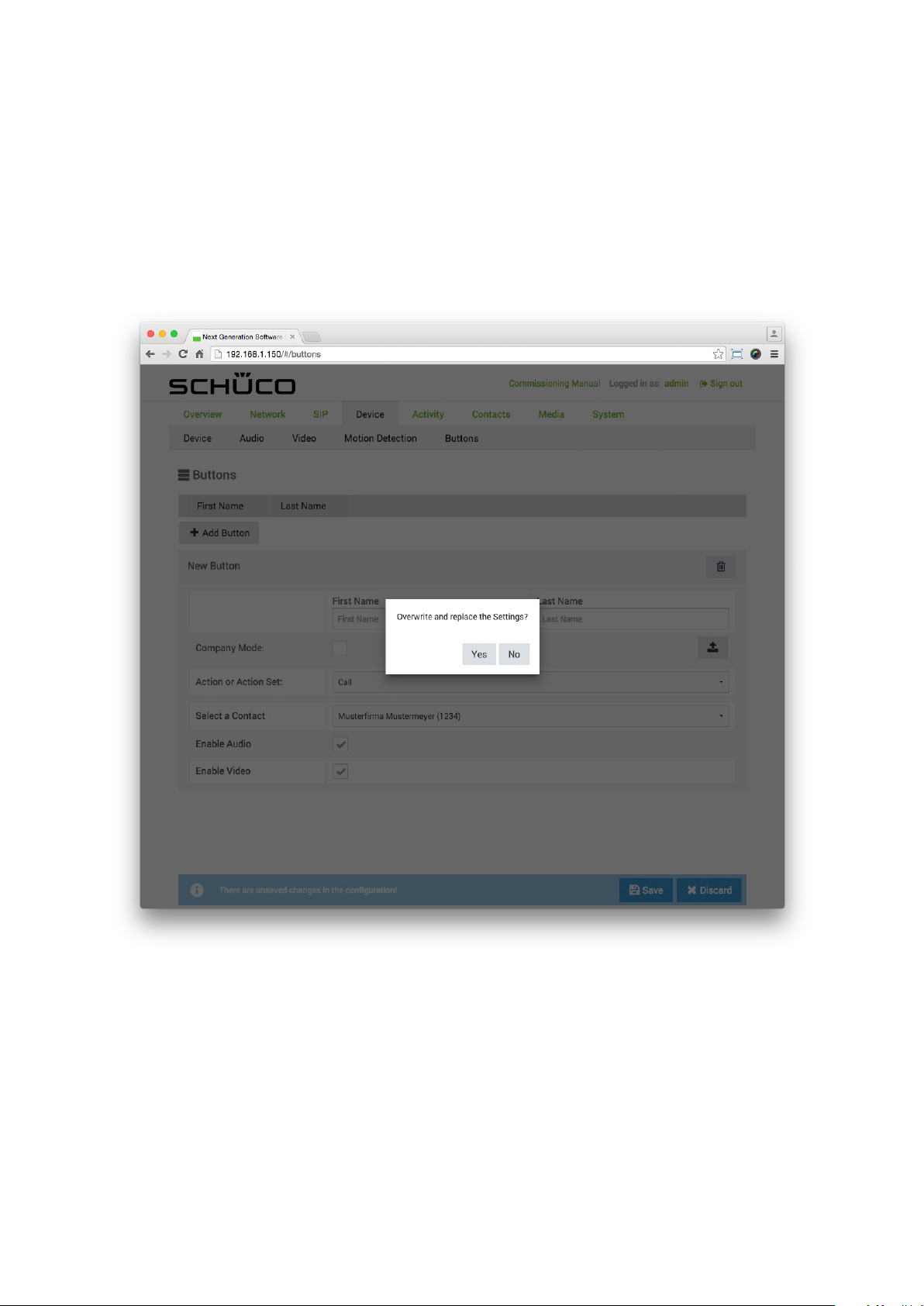
Commissioning instructions – Schüco DCS Touch Display 93
3. In the „Select contacts“ selection list, select the desired contact.
The „Overwrite settings?“ dialog box appears.
4. Click on „Yes“ to automatically copy over the elds „First name“ and „Surname“ as well as
the prole picture of the contact
Schüco de
5. Check the „Company mode“ checkbox.
6. Check the checkboxes „Activate audio“ and „Activate video“ to enable audio and images for a call.
Dok-Nr.10000432116_01
Page 92
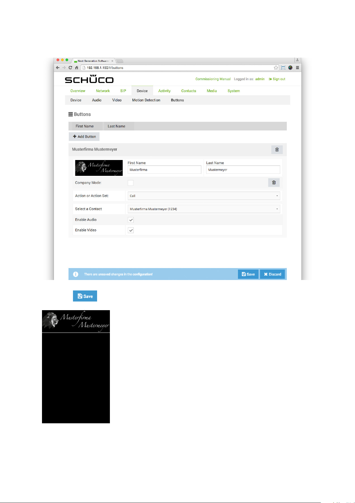
94
Schücode Commissioning instructions – Schüco DCS Touch Display
7. Click on .
Dok-Nr.10000432116_01
Page 93
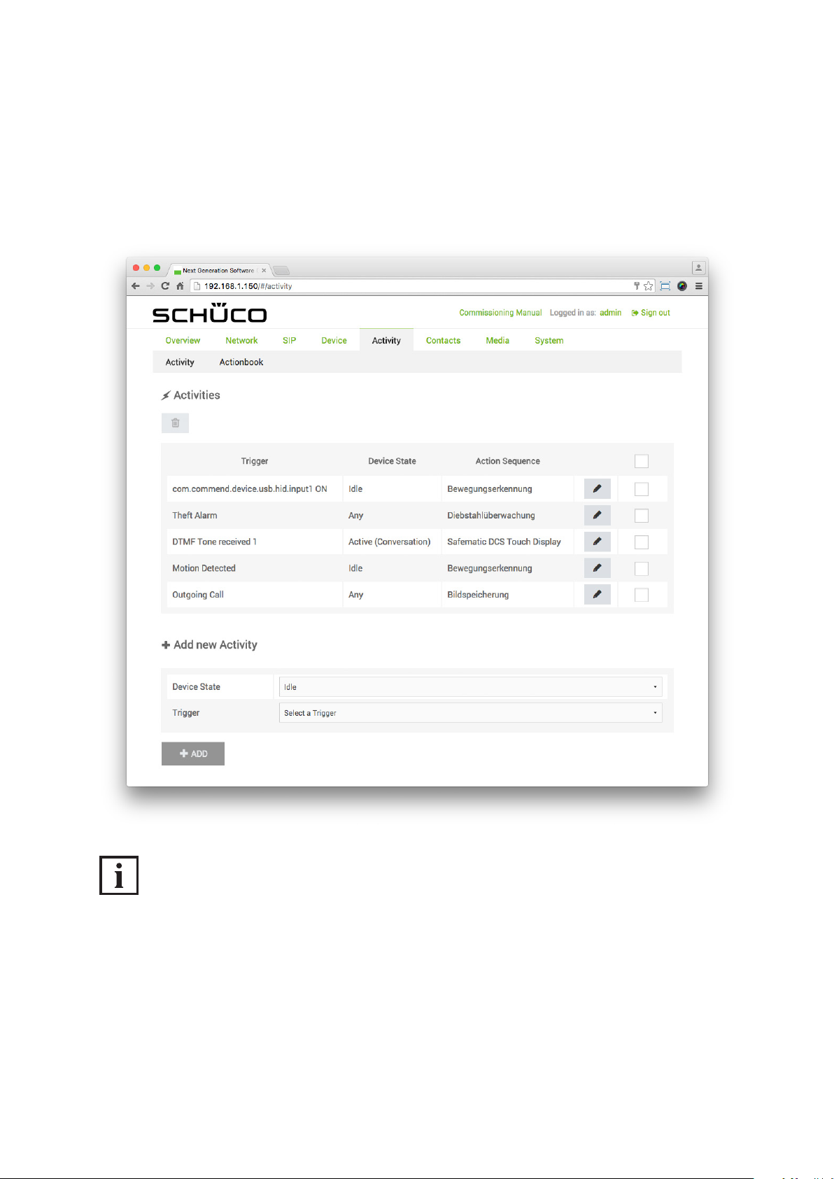
Commissioning instructions – Schüco DCS Touch Display 95
Schüco de
9.10. Activity
On the „Activity“ page, it is possible to congure triggers which trigger an action sequence after a certain event. As a result, the „Doorbell list“ or „Code entry“ view can be displayed automatically in
the event of an input change at an input, for example.
INFORMATION
Precongured activities
On the „Activity“ page, there are activities which have already been precongured.
More detailed information on these can be found under „9.14.6 Precongured activities“.
Dok-Nr.10000432116_01
Page 94
96
Schücode Commissioning instructions – Schüco DCS Touch Display
9.10.1. Activities
In the „Activities“ section, activities which have already been created can be edited or deleted.
The following options are available in the „Activities“ section:
: Click on this button to delete the selected activities.
: Click on this button to edit the respective activity.
: Check the checkboxes of all elds which you would like to delete.
9.10.2. Adding an activity card
In the „Activity“ section, new activities can be added.
The following options are available in the “Add activity card” section:
● Device status: Choose the status in which the DCS Touch Display is to trigger.
The following options are available for this:
• All: The trigger is triggered in any status of the DCS Touch Display.
• Idle: The trigger is only triggered in the “Idle” mode.
• Select: The trigger is only triggered while the access code is being entered.
• Ringing: The trigger is only triggered while calling.
• Active (conversation): The trigger is only triggered during a call.
• Error: The trigger is only triggered in the presence of a device error.
● Trigger: Select the type of event which should trigger it.
The following options are available for this:
• Outgoing call: The trigger is only triggered by outgoing calls.
• Error: The trigger is only triggered by a device error.
• Input change: The trigger is only triggered by an input change (inputs of the DCS Touch Display
and, if present, IP secure connector).
• DTMF tone received: The trigger is only triggered when a DTMF tone is received (“0” to “9”, “A”
to “D”, “*” or “#”).
• Incoming call: The trigger is only triggered by incoming calls from all or only certain contacts.
● : Click on this button to add an activity card.
Dok-Nr.10000432116_01
Page 95
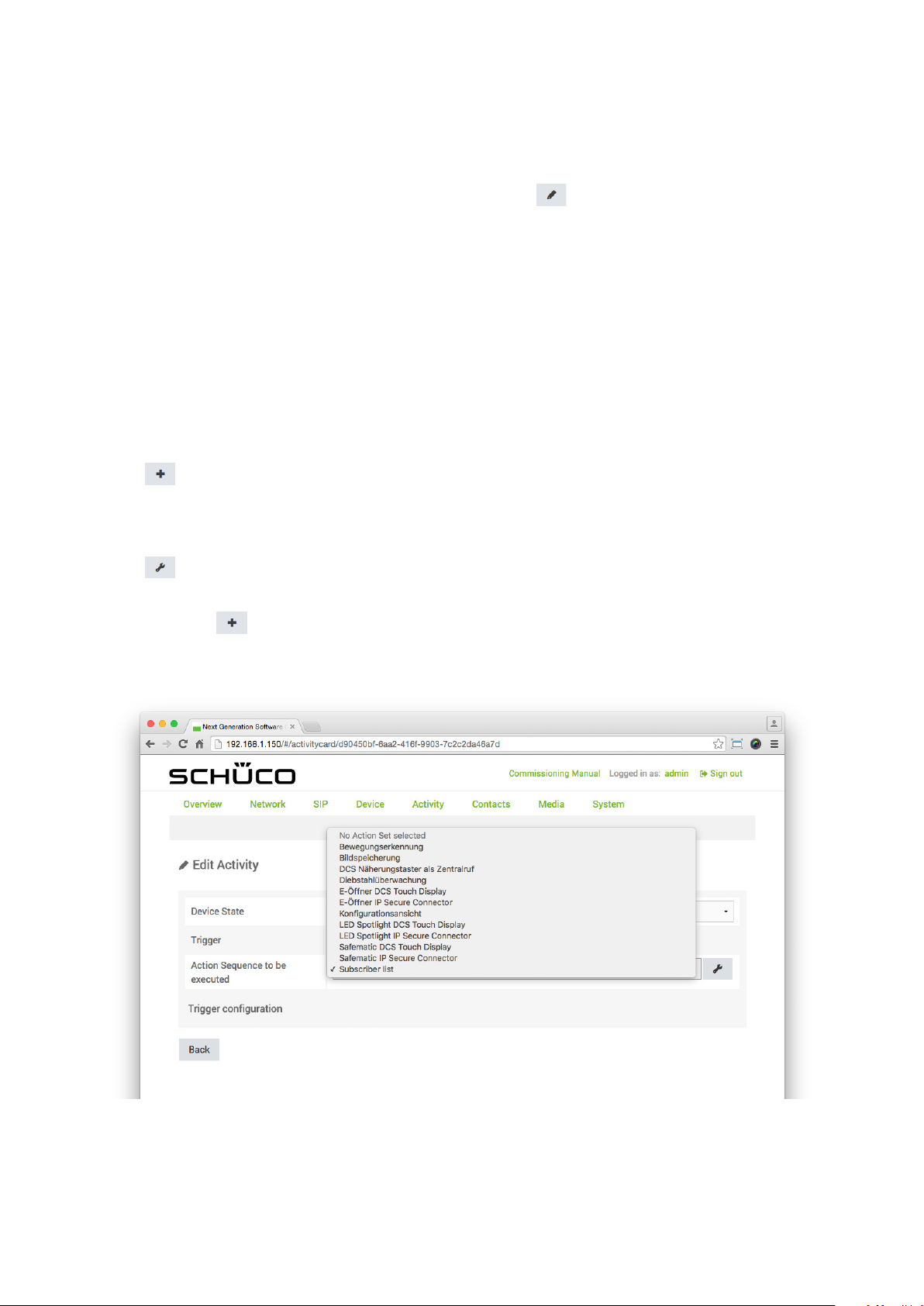
Commissioning instructions – Schüco DCS Touch Display 97
9.10.3. Editing an activity
As soon as you have clicked on for an activity, you can edit it.
The following options are available under “Edit activity”:
● Device status: Choose the status in which the DCS Touch Display is to trigger.
The following options are available for this:
• All: The trigger is triggered in any device status of the DCS Touch Display.
• Idle: The trigger is only triggered in the “Idle” device status.
• Select: The trigger is only triggered while an outgoing call is being initiated.
• Ringing: The trigger is only triggered while an incoming call is ringing.
• Active (conversation): The trigger is only triggered during a conversation.
• Error: The trigger is only triggered in the presence of a device error.
● Trigger: This shows which is the trigger in question.
● Implementing action sequence: Select a previously created action sequence in this selection list.
Schüco de
• : Click on this button to create a new action sequence on the “Action sequences” page.
It is possible to select this action sequence immediately in the “Implementing action sequence”
selection list. However, it must be congured on the “Action sequences” page before it can be
used.
• : If an action sequence has already been stored for this activity, click on this button to edit
the action sequence. Where an action sequence has been stored, this button is shown
instead of .
● Button: Select the button which is to trigger it (button in the “Doorbell list” view).
Dok-Nr.10000432116_01
Page 96
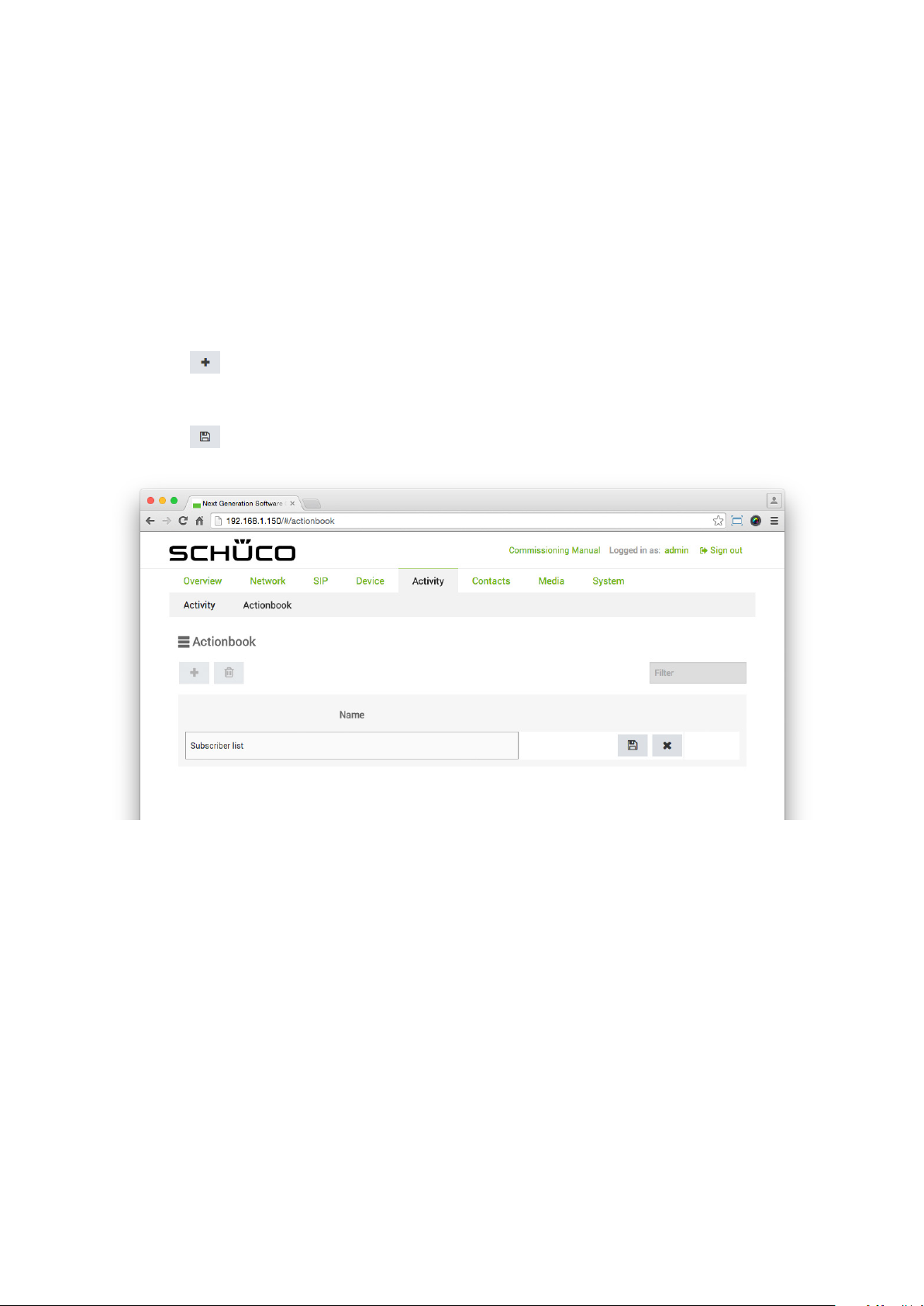
98
Schücode Commissioning instructions – Schüco DCS Touch Display
9.10.4. Creating an activity
The following example will help to explain how an activity is created on the “Activity” page.
The aim here is to display the “Doorbell list” view when the integrated camera of the
DCS Touch Display detects a movement in the “Idle” device status.
To create an action sequence to display the “Doorbell list” view and then an activity as a trigger, pro-
ceed as follows:
1. Open the “Action sequences” page via “Activity”.
2. Click on .
3. Enter a meaningful term or phrase for the action sequence in the “Name” eld (e.g. “Doorbell list”).
4. Click on .
Dok-Nr.10000432116_01
Page 97
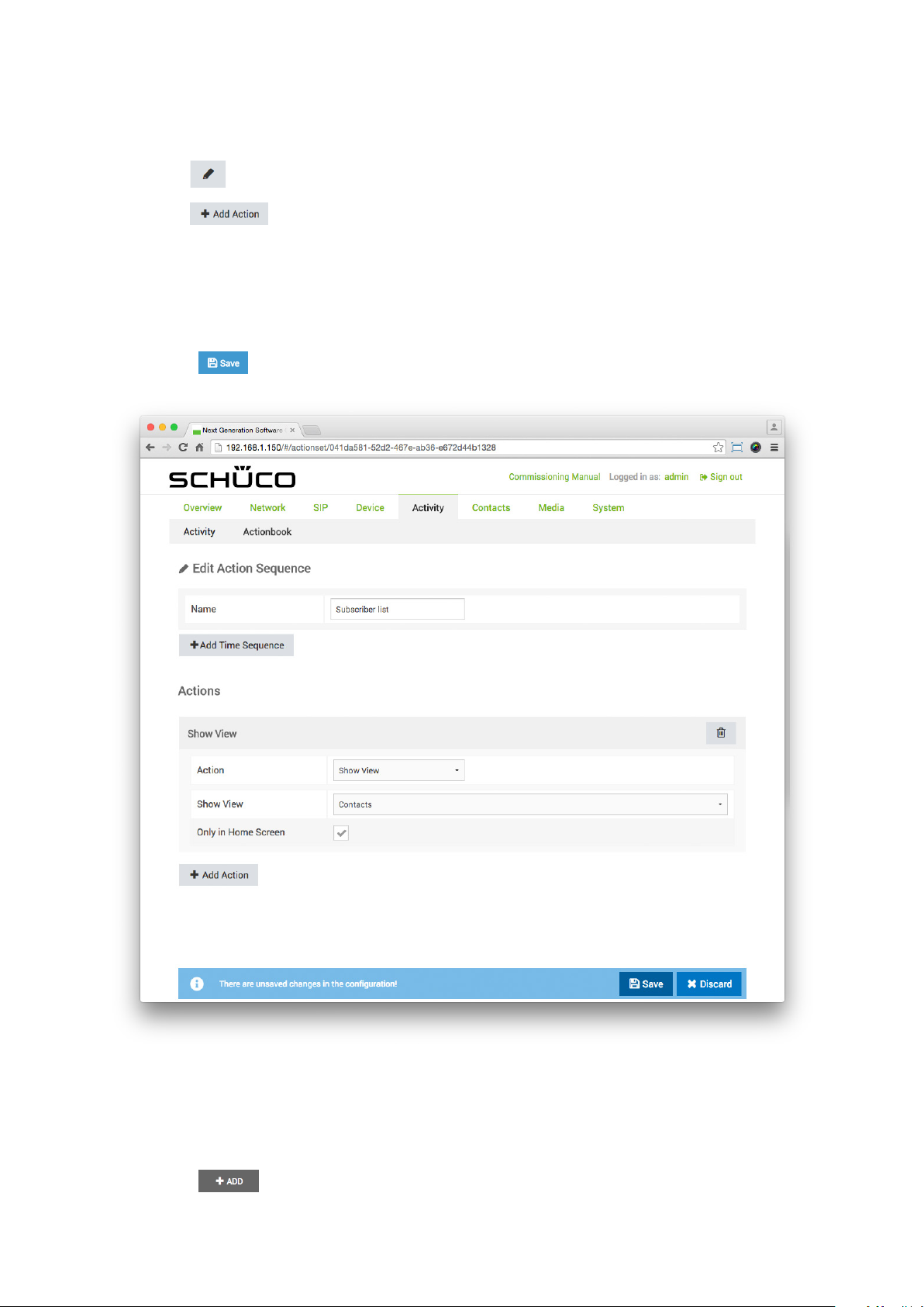
Commissioning instructions – Schüco DCS Touch Display 99
5. Click on .
6. Click on .
7. In the “Action” selection list, select the “Show view” option.
8. In the “Show view” selection list, select the “Contacts” option.
9. Check the “Only in idle mode” checkbox.
10. Click on .
Schüco de
11. Open the “Activity” page via “Activity”.
12. In the “Device status” selection list, select the “Idle” option.
13. In the “Trigger” selection list, select the “Motion detection” option.
14. Click on .
Dok-Nr.10000432116_01
Page 98
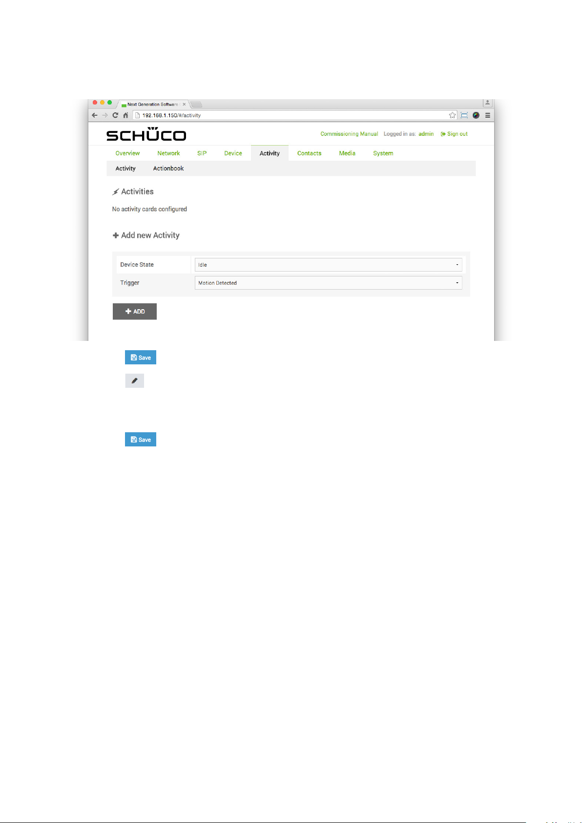
100
Schücode Commissioning instructions – Schüco DCS Touch Display
15. Click on .
16. Click on .
17. In the “Implementing action sequence” selection list, select the action sequence previously
created (e.g. “Doorbell list”).
18. Click on .
Dok-Nr.10000432116_01
Page 99
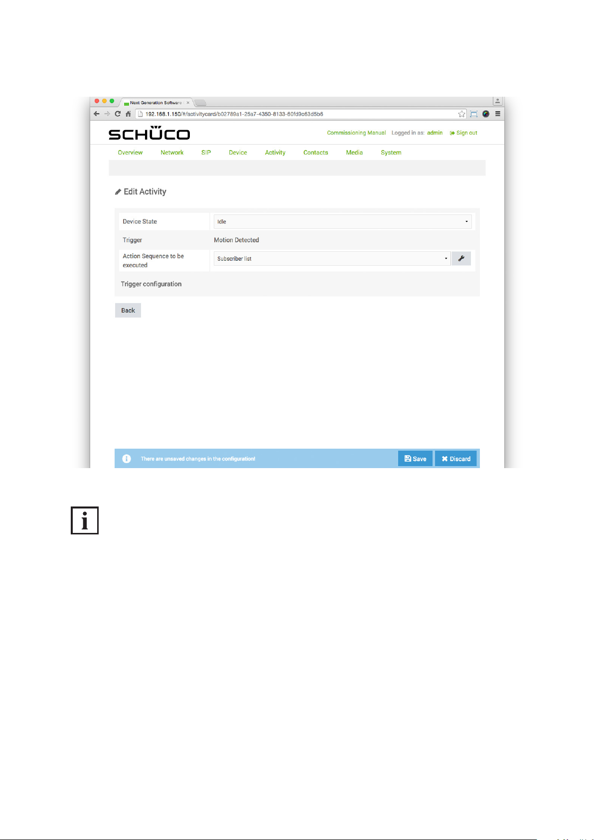
Commissioning instructions – Schüco DCS Touch Display 101
Schüco de
INFORMATION
Motion detection settings
More detailed information about the conguration of motion detection can be found
under „9.11 Motion detection“.
Dok-Nr.10000432116_01
Page 100

102
Schücode Commissioning instructions – Schüco DCS Touch Display
9.10.5. Precongured activities.
The following activities are precongured in the factory and may be adopted, changed or deleted
as required:
● DCS Touch Display - IN 1 one: If a DCS proximity switch is provided for installation, the
“Motion detection” action sequence is triggered via this activity so that the “Doorbell list” view is displayed in the event of an input change (see also “9.15.6 Precongured action sequences”).
The activity is congured as follows as standard:
• Device status: Idle
• Implementing action sequence: DCS proximity switch
• Input: DCS Touch Display - IN
• Input value: One
● Anti-theft alarm: If the anti-theft device for the DCS Touch Display is to be activated,
the “Anti-theft monitoring” action sequence is triggered via this activity so that the “Alarm on” symbol
is displayed and the “Alarm.wav” audio le is played
(see also “9.15.6 Precongured action sequences”).
The activity is congured as follows as standard:
• Device status: All
• Implementing action sequence: Anti-theft monitoring
● DTMF tone received 1: If a SafeMatic is provided for installation, the “Safematic DCS Touch Display
” action sequence is triggered via this activity so that the door opener is actuated when the
DTMF tone “1” is received (see also “9.15.6 Precongured action sequence”).
The activity is congured as follows as standard:
• Device status: Active (conversation)
• Implementing action sequence: SafeMatic DCS Touch Display
• DTMF tone: 1
● Motion detection: If movement has been detected by the motion detection function in the integrated
camera, the “Motion detection” action sequence is triggered via this activity and the “Doorbell list”
view is displayed (see also “9.15.6 Precongured action sequence”).
• Device status: Idle
• Implementing action sequence: Motion detection
● Outgoing call: If a call is triggered on the DCS Touch Display, the “Image storage” action sequence
is triggered via this activity and a snapshot is taken (see also “9.15.6 Precongured action
sequence”). This snapshot can be downloaded on the “Photos” page or deleted
(see also “9.17.2 Photos”).
• Device status: All
• Implementing action sequence: Image storage
INFORMATION
Privacy
The image rights belong to the person who was photographed.
Dok-Nr.10000432116_01
 Loading...