

Page 1
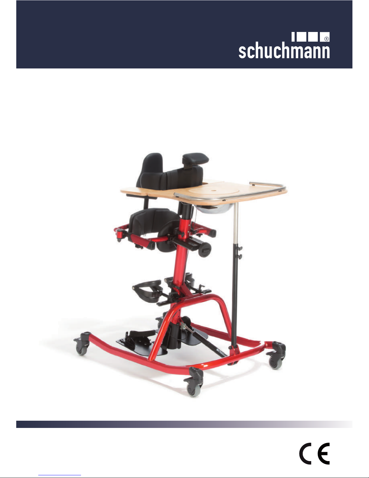
TIM
The angle adjustable upright trainer
Instructions for use
Page 2

2
Dear Customer,
At this point we would like to thank you for placing your trust in our company and
for purchasing our product.
We ask you to read through the Instructions for use carefully prior to initial commissioning of the product, and to observe them. Please note that guidelines and
representations in these Instructions for use may deviate from your product due to
differing equipment.
We reserve the right to make technical modi cations.
Important information!
Ensure that these Instructions for use remain with the product.
Your Schuchmann Team
Page 3

3
Content
1. Preparation of the upright trainer for use ......................................................................................4
1.1 Delivery .........................................................................................................................................4
1.2 Safety measures prior to use ........................................................................................................4
1.3 Safe disposal ................................................................................................................................4
1.4 Where to store the Instructions for use .........................................................................................4
2. Product description ..........................................................................................................................5
2.1 Material information ......................................................................................................................5
2.2 Handling and transport .................................................................................................................5
2.3 Application areas, use according to the intended purpose ...........................................................6
2.4 Use not in accordance with the intended purpose / warning guidelines .......................................7
2.5 Equipment for basic model ...........................................................................................................7
2.5.1 Equipment acc. HMV (Medical Aids Register).....................................................................7
2.6 List of accessories ........................................................................................................................8
2.7 Product overview ..........................................................................................................................8
2.8 General settings............................................................................................................................9
2.9 Getting in and out .......................................................................................................................10
3. Settings ...........................................................................................................................................11
3.1 Angular adjustment of the central column ..................................................................................11
3.2 Height adjustment on the central column ...................................................................................11
3.3 Footplate .....................................................................................................................................12
3.4 Divided footplate .........................................................................................................................12
3.5 Heel edges..................................................................................................................................13
3.6 Footstraps ...................................................................................................................................13
3.7 Knee pelotte pads .......................................................................................................................13
3.8 Pelvic frame ................................................................................................................................14
3.9 Combined spine and pelvic pelotte pad ......................................................................................15
3.10 Buttocks pelotte pad .................................................................................................................16
3.11 Ventral pelvic pelotte pad ..........................................................................................................16
3.12 Chest pelotte pad with lateral guide .........................................................................................17
3.13 Backstrap ..................................................................................................................................17
3.14 Back pelotte pad .......................................................................................................................18
3.15 Headrest ...................................................................................................................................18
3.16 Therapy tables ..........................................................................................................................19
3.16.1 Therapy table with depression ..............................................................................................19
3.16.2 Adjustable arm supports ........................................................................................................20
3.17 Chin support .............................................................................................................................20
4. Repairs and cleaning .....................................................................................................................21
4.1 Cleaning......................................................................................................................................21
4.2 Repairs .......................................................................................................................................21
4.3 Spare parts .................................................................................................................................21
4.4 Duration of use and re-use .........................................................................................................21
5. Technical data .................................................................................................................................22
6. Guarantee ........................................................................................................................................22
7. Identication ...................................................................................................................................23
7.1 EC declaration of conformity.......................................................................................................23
7.2 Serial number / date of manufacture ..........................................................................................24
7.3 Product version ...........................................................................................................................24
7.4 Issue of the document ................................................................................................................24
7.5 Name and address of the manufacturer, specialist dealer supplying the product .....................24
Page 4

4
1. Preparation of the upright trainer for use
1.1 Delivery
On receiving the product, please check it for completeness, lack of faults and check
it for any transport damage.
Inspect the goods in the presence of your forwarder
Should transport damage have occurred, please arrange for an inventory (determination of the faults) to be made in the presence of the forwarder. Please send a
complaint in writing to the specialist dealer responsible.
1.2 Safety measures prior to use
Correct usage of the upright trainer requires precise and careful training of the accompanying person. We ask you to read through the Instructions for use carefully
prior to initial commissioning of the upright trainer, and to observe them. Cushioned
parts may become warm when exposed to direct sunlight. Cover these parts or
protect the equipment from direct sunlight.
1.3 Safe disposal
In order to preserve and protect the environment, to prevent environmental pollution, and to improve the recycling of raw materials, please note the disposal instructions in points 1.3.1 and 1.3.2.
1.3.1 Packaging
The product packaging should be stored in case the product needs to be transported again. Should you have to return the product for repairs or in case of a guarantee claim, please if possible use the original box so that the product is optimally
packaged.
Separate the packaging materials for recycling according to their classication. Do
not leave packaging materials unattended, as they are a possible source of danger.
1.3.2 Product
Separate the raw materials used in the product for recycling according to their
classication (see material information under 2.1).
1.4 Where to store the Instructions for use
Please store these Instructions for use carefully and ensure that these Instructions
for use remain with the product in case of re-use.
Page 5

5
2. Product description
2.1 Material information
The base frame and the individual elements are made of steel which is non-corroding and powder-coated. All body supports (except for the knee pelotte pads) are
padded and covered. The covers are made of 100% polyester or polyamide textile
substrate, and are ame resistant (according to DIN EN 1021-1+2).
2.2 Handling and transport
The upright trainer is not designed to be carried, as it is tted with castors. Should
you have to carry the equipment due to obstacles, ensure that all moving parts are
tightened.
Then two people should position themselves next to the upright trainer, grip it on
the left and right of the frame and carry it to the required location. To transport the
upright trainer, reduce all adjustments to their most compact size (fold up pelvic
frame, set lowest height etc.)
Page 6

6
Never correct posture using force or strong pressure!
2.3 Application areas, use according to the intended purpose
Indications
The TIM upright trainer is designed for interior use and serves to train standing in
users who can hardly stand or who cannot stand, in particular due to:
• Paraplegia
• Advanced multiple sclerosis
• Cerebral paresis
• Muscular dystrophy
Contraindications
In general, the indications for standing should be approved by a doctor or orthope-
dist. It should therefore be claried prior to procurement whether contraindications
exist for the patient. In general, any type of pain represents a contraindication. No
upright trainer care should be conducted without establishing prior to use whether
the patient has an abnormal foot position which requires medical attention.
Depending on the disease symptoms and therapy, please clarify how long the user
may stand in the upright trainer. The following symptoms may occur in some cases:
• Circulation problems
• Pain in the leg and back areas
• Spastic seizures
It must also be claried whether the user can be brought into full standing position.
For many users, only standing in a bent position is possible at rst.
Page 7

7
CAUTION!
2.4 Use not in accordance with the intended purpose / warning guidelines
• Ensure that the upright trainer is only used by one child/teenager.
• Never leave the child unattended in the upright trainer.
• Correct usage of the upright trainer requires precise and careful training of the
accompanying person.
• The max. load (see Point 5) may not be exceeded.
• Do not use the upright trainer if it has defective, worn or missing parts.
• For reasons of re safety, the upright trainer may not be placed close to an open
re or any other strong source of heat such as electric or gas heaters.
• Only use accessories and spare parts made by Schuchmann, otherwise you will
endanger the child.
• Only use the upright trainer if all components have been correctly mounted and
adjusted.
• When adjusting the upright trainer there is the risk of trapping or crushing limbs.
• Users who have difculty reading must have someone read these Instructions for use
aloud so that they understand how to use the standing exercise trainer.
2.5 Equipment for basic model
• Base frame with height adjustable footplate
• Angular adjustment of the central column via gas pressure spring from (-) 15° 30°
• Incl. chest pelotte pad with lateral guide and buttocks pelotte pad
• Pelvic frame height and depth adjustable, pelvic position adjustable via hand
crank
• Incl. knee pelotte pads with patella recess, each 3-dimensionally adjustable
• Therapy table with edge
• 4 braked castors (75 mm) with total locking device
2.5.1 Equipment acc. HMV (Medical Aids Register)
Acc. the HMV (Medical Aids Register), the upright trainer TIM requires the provision
of heel edges and footstraps.
Page 8
8
2.6 List of accessories
• Chest pelotte pad with lateral guide
(optional angular adjustment)
• Buttocks pelotte pad
• Ventral pelvic pelotte pad
• Pelvic guidance pelotte pad with
lateral guide
• Combined spine and pelvic pelotte
pad
• Back pelotte pad
• Backstrap
• Knee pelotte pads (optional with
positioner brackets)
• Headrest
• Chin support
• Therapy table (with / without therapy
table / with / without arm supports)
• Footplate
• Divided footplate
• Heel edges
• Footstraps
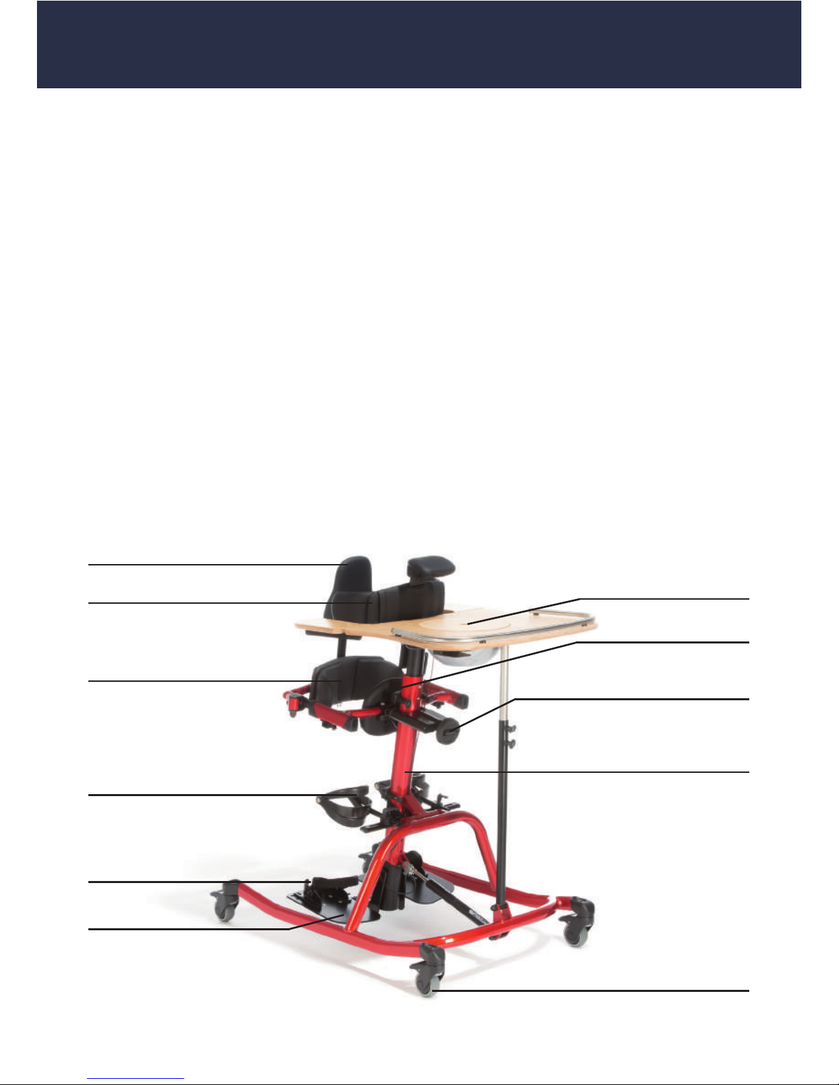
Back pelotte pad
Heel edges
Pelvic guidance pelotte pad
with lateral guide
Divided footplate
Central column; can be adjusted
via gas pressure
spring from (-)15 - 30°
4 braked castors (75mm)
with total locking device
Hand crank for adjustment of the
pelvic position
Ventral pelvic
pelotte pad
Knee pelotte pads with
adjustable positioner brackets
Therapy table with arm
supports and depression
Chest pelotte pad with lateral guide
2.7 Product overview
The Fig. below is intended to show you the designation of the most important com-
ponents as well as the terms which you will nd in these Instructions for use.
Page 9
9
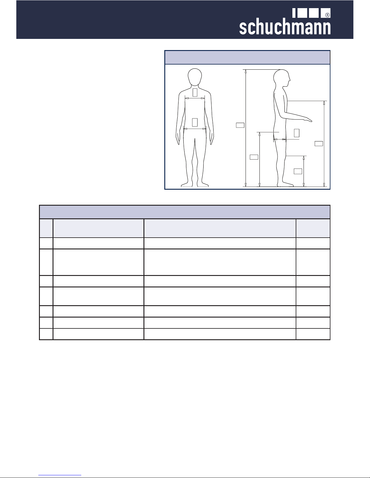
2.8 General settings
TIM is completely assembled and
delivered in the smallest possible
setting. Before the user is placed
into the upright trainer, the necessary presettings must be carried
out.
User dimensions
E
A
B
F
D
G
C
Presettings
Taking the user's dimensions
Carrying out adjustments to the upright trainer see
A
Body size Footplate to headrest
3.2 + 3.15
B
Pelvic height
Adjust the footplate up to the upper edge of the
buttocks pelotte pad support, then adjust downwards by approx. 5 cm.
3.3 + 3.10
C
Pelvic depth Depth of the buttocks pelotte pad
3.10
D
Pelvic width
Width of the combined spine and
Pelvic pelotte pad
3.9
E
Sternum height Height of the chest pelotte pad with lateral guide
3.9
F
Chest width Width of the chest pelotte pad with lateral guide
3.12
G
Knee height Height of knee pelotte pads
3.7
Page 10
10
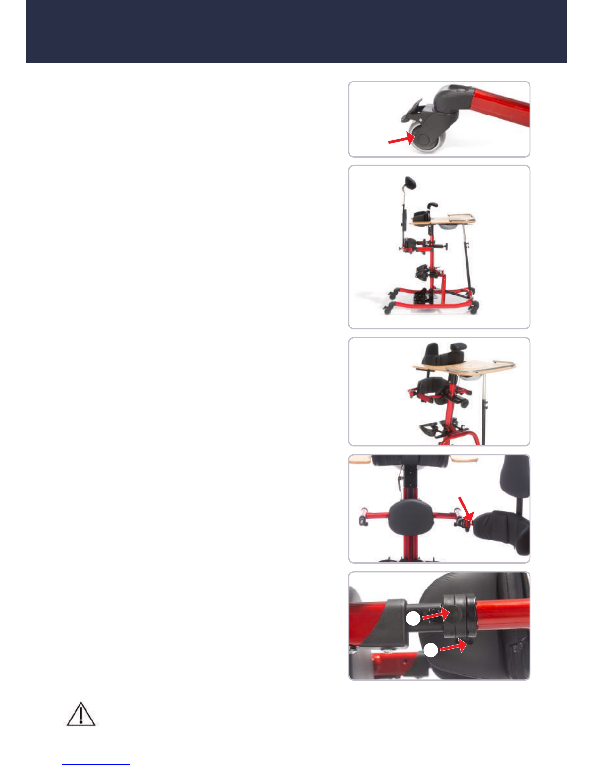
2.9 Getting in and out
Once all presettings have been carried out, ple-
ase rst lock all four castors for getting in and out
(A).
Now bring the central column into vertical position (see Point 3.1) and open the swivel arm of the
pelvic frame (B).
To open the pelvic frame, please press both safe-
ty buttons simultaneously (C+D)
Now you can move the user in their wheelchair /
buggy etc towards the upright trainer and apply
the locking devices on the respective device. Lift
the user from the wheelchair / buggy and place
them into the upright trainer before closing the
pelvic frame once more.
Now you can undertake the ne adjustments on
the individual components. Please observe here
the guidelines on the adjustment of the respective components (see Point 3).
Only have the user get in and out of the product on stable and at
ground.
A
B
C
D
Page 11

11
3. Settings
Settings and adjustments to the product or accessories may only be made by people who have been given the necessary instructions by a medical product advisor.
Please ensure that none of the user's extremities are in the respective area when
making adjustments to avoid the risk of injury.
3.1 Angular adjustment of the central column
The central column can be adjusted using a gas
pressure spring, whereby the therapy table remains at a preset angle. Please secure the upright trainer against inadvertent rolling away by
applying the locking devices on the castors.
For angular adjustment, operate the pushbutton
switch (B) located under the table, bring the central column into the required position and release
the pushbutton switch again.
A
3.2 Height adjustment on the central column
The black inner prole, which is located in the upper part on the central column, can be pulled out
and is thus adjustable in height.
In order to adjust the carriage in the upper area
(B), loosen the screws (C+D) and bring the carriage into the required position.
C
D
B
Only undertake height adjustment if there is no-one in the upright
trainer!
After each adjustment, please re-tighten all screw connections!
Hold the carriage tightly, otherwise it will slip into the central column
under its own weight.
Page 12
12
After each adjustment, please re-tighten all screw connections!
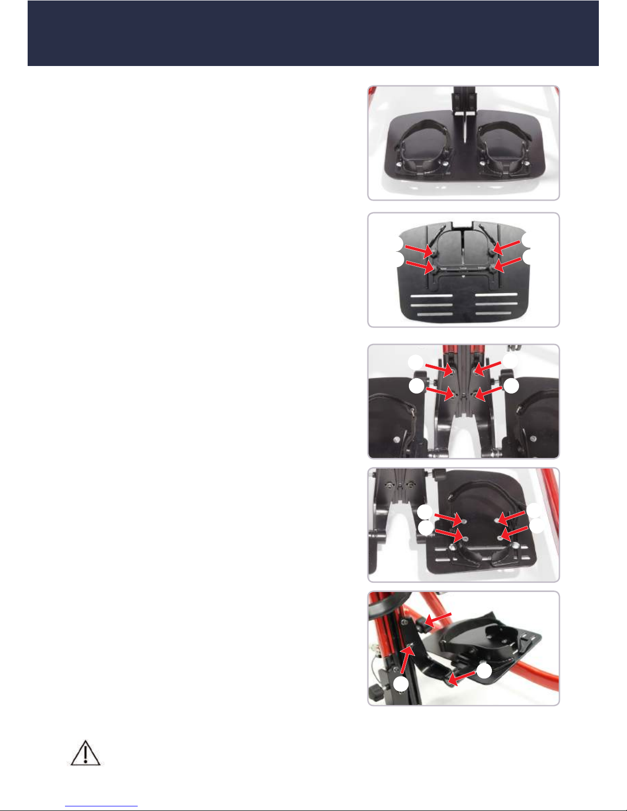
3.3 Footplate
The footplate is adjustable in height and can be
altered via the inner prole using the height adjustment on the central column (see Point 3.2).
To adjust the depth, loosen the star screw (A+B),
which is located under the footplate. Now bring
the footplate into the required depth position.
3.4 Divided footplate
The divided footplate is height and width adjustable with additional angular adjustment for a
pointed foot setting.
In order to adjust the height of the divided footplate, loosen the screws (C and D) and bring the
divided footplate into the required position.
In order to adjust the divided footplate in width,
loosen the screws (E+F) and bring the divided
footplate into the required position.
In order to adjust the divided footplate in terms
of the angle for abduction of the legs, loosen the
screw (G) and turn the star handle (H). A further
angle adjustment,
e.g. for pointed foot position, can be undertaken
via the Allen screw (I). Using a ratchet joint, the
entire divided footplate can be adjusted at an
angle.
C
D
C
D
E
F
E
F
G
H
I
A
A
B
B
Page 13
13
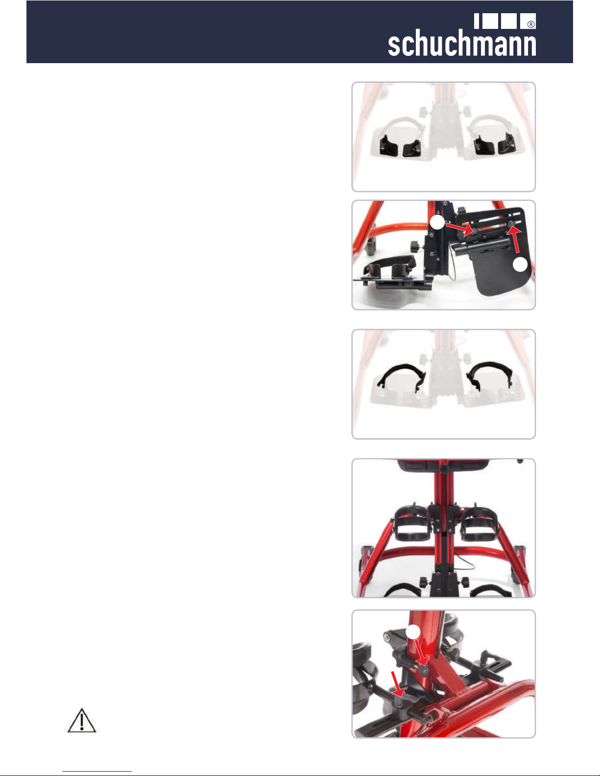
3.5 Heel edges
The heel edges are mounted onto the footplate
or the divided footplate. They can be adjusted in
width or angle. The height or depth adjustment is
undertaken via the footplate or divided footplate,
see Point 3.3 or 3.4
In order to adjust the width or the angle, loosen
the wing screws (A) below the (divided) footplate
and bring the heel edges into the required position.
In addition, you can adjust the depth by loosening
the screws (A) and positioning them in a perforated pattern at a different point.
A
A
3.6 Footstraps
The footstraps can only be used in connection
with the heel edges.
In order to adjust the footstraps, loosen the hook
and eye fastener and bring the footstrap into the
required position.
3.7 Knee pelotte pads
The knee pelotte pads are adjustable in height,
angle and depth. The distance between the knee
pelotte pads can also be adjusted.
In order to adjust the height, please hold the knee
pelotte pad tight, loosen the wing screws (B) and
bring the knee pelotte pad support into the required position.
In order to adjust the depth, the angle and the
width, please loosen the clamping lever (C) and
bring the knee pelotte pad into the required position.
After each adjustment, please re-tighten all screw connections!
B
C
Page 14
14
After each adjustment, please re-tighten all screw connections!
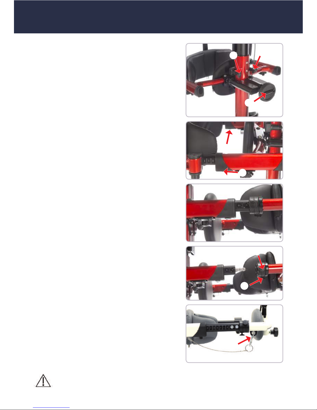
3.8 Pelvic frame
The pelvic frame can be adjusted in height and
in depth.
In order to adjust the pelvic frame in height, loosen the wing screws (A) and bring the pelvic
frame into the required position.
The patient can be straightened up using the
hand crank (B). It is also possible to adjust the
depth on the pelvic frame yourself. To do this,
loosen the screws (C) and pull the rear part of
the pelvic frame evenly on both sides out of the
depth adjustment. Ensure that both inner tubes
on the depth adjustment are extended by an
equal amount. Only in this way can the smooth
function of the pelvic frame locking mechanism
be guaranteed.
The pelvic frame has a safety lock. In order to
open the swivel arm on the pelvic frame, press
the two buttons (D+E) simultaneously. Now you
can open the swivel arm on the pelvic frame.
To close, insert the lock on the locking bolt and
push it forwards with force. When closing, press
the pelvic frame back with force. The locks must
engage audibly and the locking bolt must be covered by the lock.
In addition, the pelvic frame is secured with a
child safety lock (F) in form of a snap hook. Before opening the pelvic frame, the snap hook must
be removed and be reattached after closing the
pelvic frame.
A
A
C
C
B
D
E
F
Page 15
15
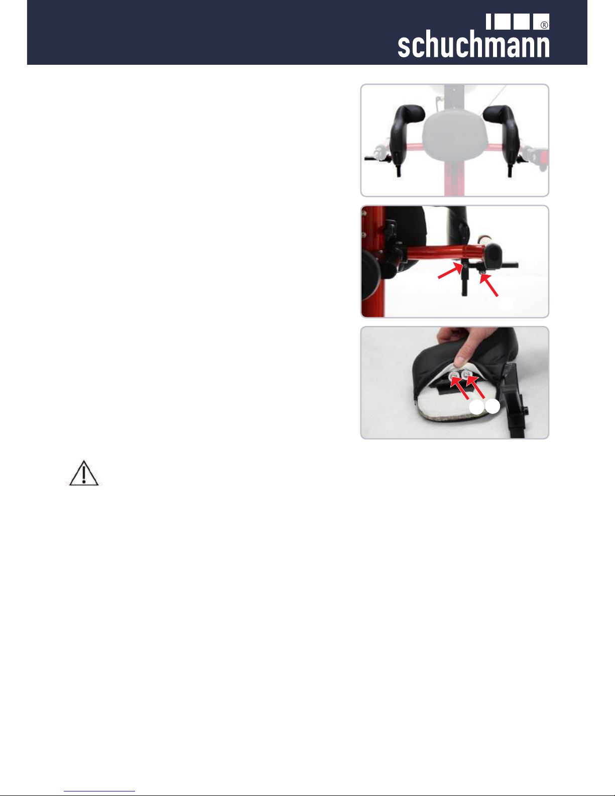
3.9 Combined spine and pelvic pelotte pad
The combined spine and pelvic pelotte pad is
width, height and depth adjustable. The height
and the depth of the combined spine and pelotte
pad can on the one hand be adjusted as a whole
via the pelvic frame (see Point 3.8).
In addition, the height can be adjusted by loosening the screw (A). Now bring the combined spine
and pelvic pelotte pad into the required position.
In order to adjust the width, please loosen the
screw (B and bring the combined spine and pelvic pelotte pad into the required width position.
In order to adjust the depth, pull the cover from
the pelotte pad and loosen the screws (C). Now
bring the combined spine and pelvic pelotte pad
into the required depth position.
A
B
C
C
After each adjustment, please re-tighten all screw connections!
Page 16

16
After each adjustment, please re-tighten all screw connections!
3.10 Buttocks pelotte pad
The height and the depth of the buttocks pelotte
pad can be adjusted as a whole via the pelvic
frame (see Point 3.8).
In addition, the buttocks pelotte pad can be assembled in three height positions on the pelvic
frame. To do this, loosen the screws (A) at the
rear side of the pelvic frame. Now you can mount
the buttocks pelotte pad in the upper, central or
lower height adjustment (B).
3.11 Ventral pelvic pelotte pad
The ventral pelvic pelotte pad can be adjusted in
depth and height. The depth and height adjustment are undertaken via the pelvic frame as a
whole (see Point 3.8).
In addition, the ventral pelvic pelotte pad can be
mounted in three height positions. To do this, extend the pelvic frame to its maximum depth using
a hand crank (see Point 3.3). Now you can loosen the screws (C). Now bring the ventral pelvic
pelotte pad into the upper (D), central (E) or lower
(F) height adjustment.
C
C
A
A
B
B
D
D
E
E
F
F
Page 17
17
After each adjustment, please re-tighten all screw connections!
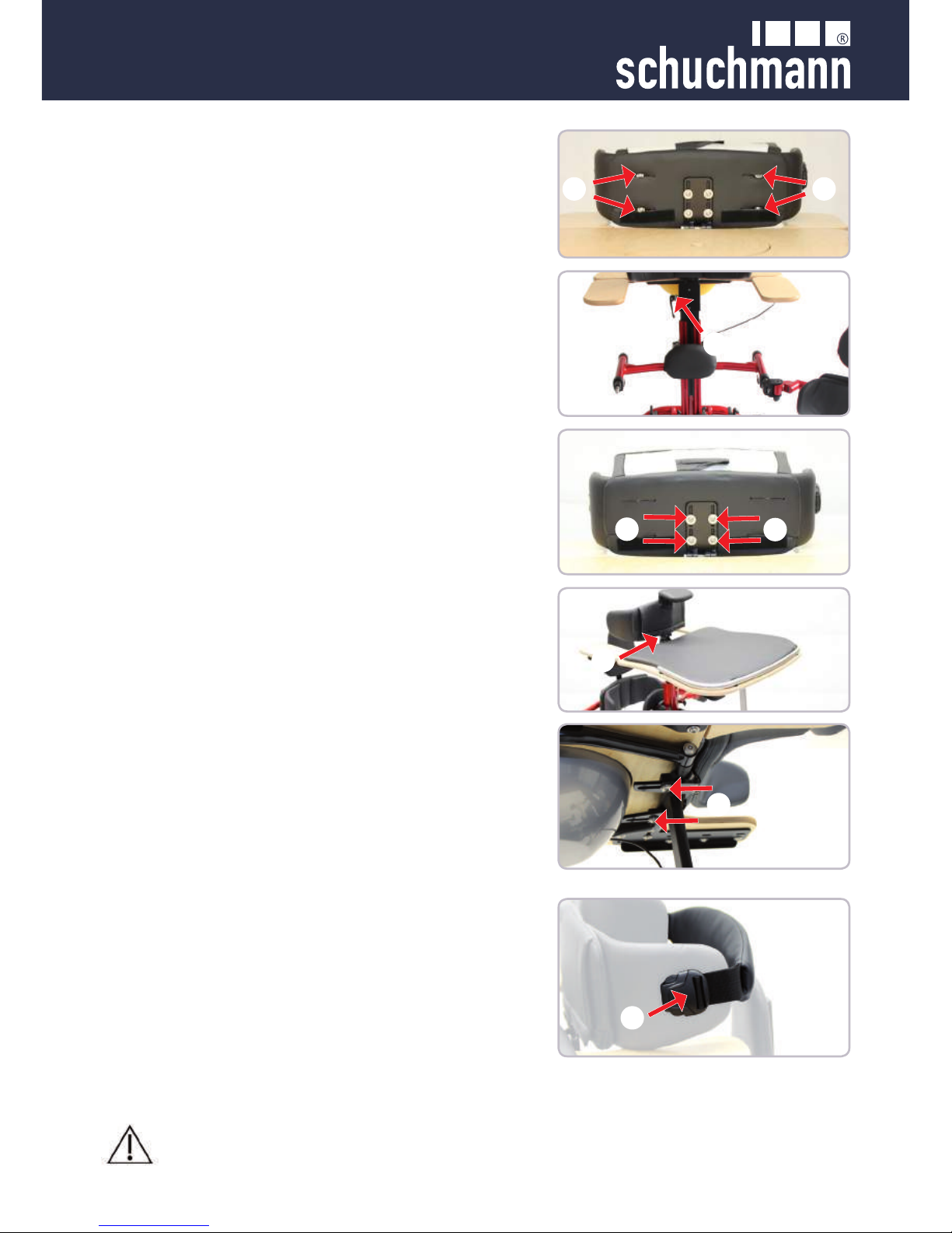
3.12 Chest pelotte pad with lateral guide
The chest pelotte pad with lateral guide is adjustable in width and height, also with optional angular adjustment.
In addition, the height can also be adjusted via
the height adjustment on the central column (see
Point 3.2.)
The chest pelotte pad support can be adjusted as
a whole in height via the clamping lever. Loosen
the clamping lever (B) and bring the support with
the chest pelotte pad into the required position.
In order to adjust the height on the chest
pelotte pad itself, please loosen the
four hexagon socket screws (C) and bring the
chest pelotte pad into the required position.
In order to adjust the width and the angle, please
remove the chest pelotte pad cover, loosen the
four hexagon socket screws (A) and bring the lateral guide into the required position.
In order to adjust the angle of the adjustable
chest pelotte pad (D), bring the chest pelotte pad
into the required position.
In order to adjust the depth of the chest, loosen
the two hexagon socket screws (E) and bring it
into the required position.
A A
C
C
3.13 Backstrap
The backstrap is attached to the chest pelotte
pad with lateral guide.
The strap can be opened or closed using a socket lock (F). The strap can be adjusted in length
via the strap guide.
Height and depth adjustments can be undertaken
via the chest pelotte pad with lateral guide (see 3.10)
F
B
D
E
Page 18
18
After each adjustment, please re-tighten all screw connections!
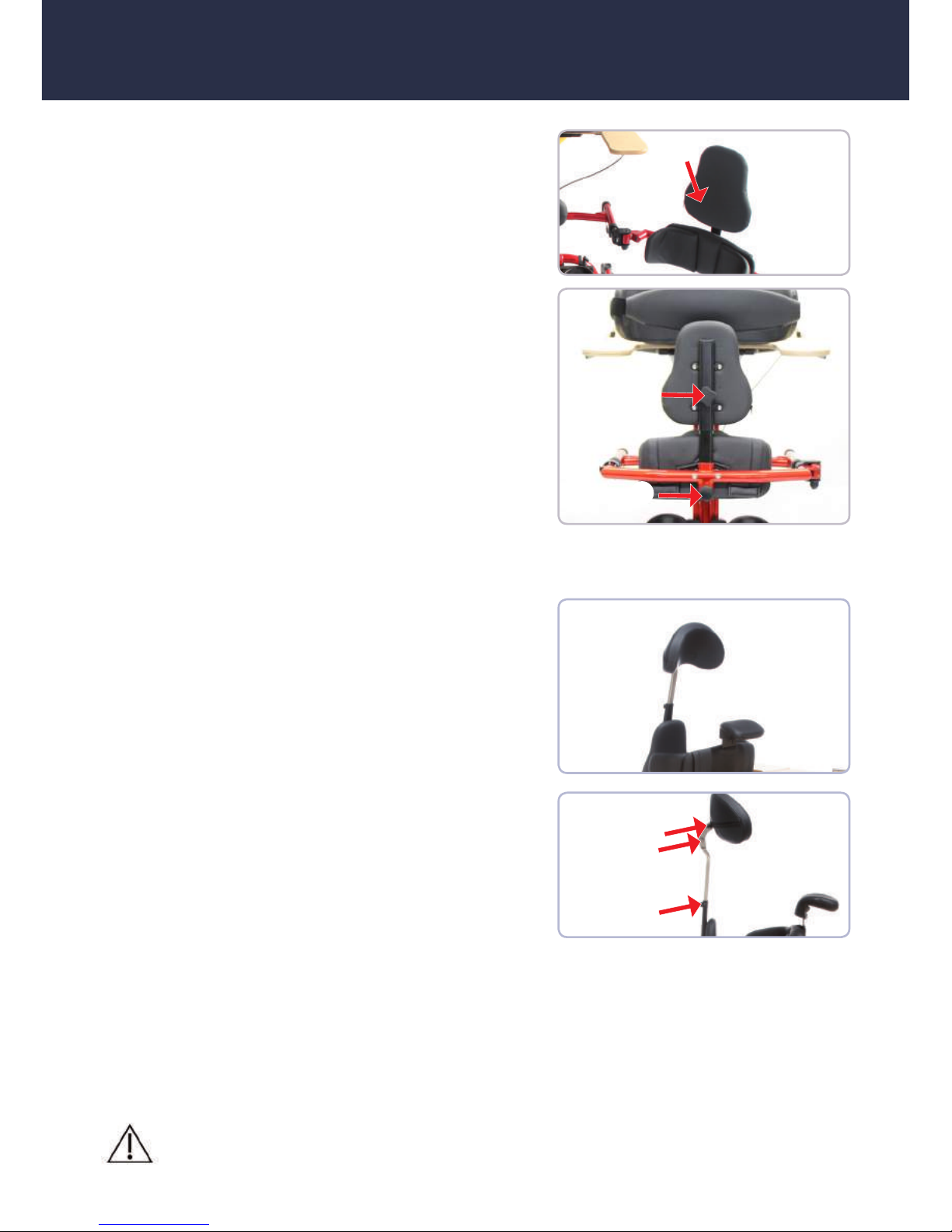
3.14 Back pelotte pad
The height and the depth of the back pelotte pad
can be adjusted as a whole via the pelvic frame
(see Point 3.8).
The back pelotte pad (A) itself can also be adjusted in height, is mounted on the swivel arm of the
pelvic frame and can be swivelled over this frame
to the side.
In order to adjust the height, please loosen the
rotary handle (B) at the rear of the back pelotte
pad and bring it into the required position.
The back pelotte pad features a safety catch (C).
In order to install or deinstall the back pelotte
pad, pull the catch (C) towards you. Now you can
remove or install the back pelotte pad by taking it
out of the support or inserting it. After assembly,
rmly tighten the catch (C) by turning it in order to x the back pelotte pad.
A
C
B
3.15 Headrest
The headrest height, depth and angle can be adjusted. It can only be used in combination with
the back pelotte pad.
The height can be adjusted via the back pelotte
pad (see Point 3.14) or via the height adjustment
of the pelvic frame (see Point 3.8).
In order to adjust the height separately, please
loosen the grub screw (E) at the rear of the back
pelotte pad and bring the headrest into the required position.
In order to adjust the depth and/or the angle, please loosen the screws (D).
E
D
Page 19
19
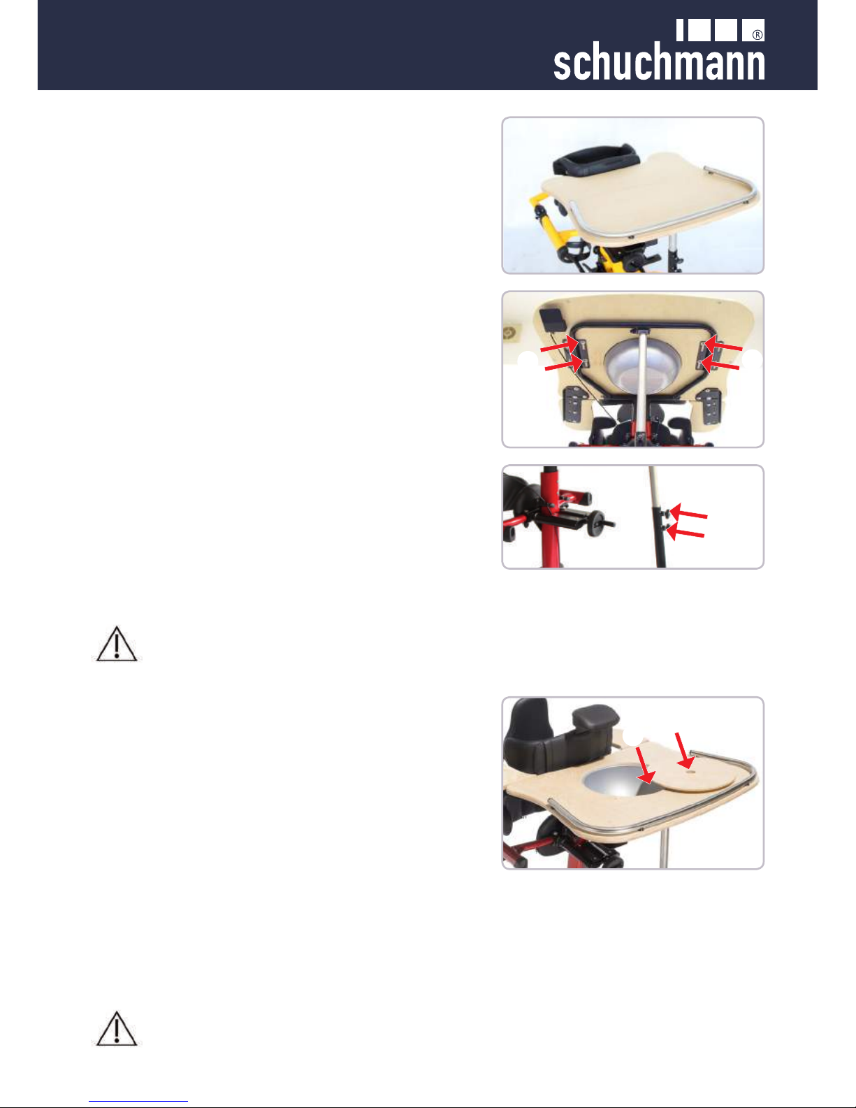
3.16 Therapy tables
Four therapy tables are available in total: One
version without a depression and arm supports,
one version with a depression, one version with
arm supports and one version with a depression
and arm supports.
The therapy table can be adjusted in depth,
height and angle.
The height adjustment of the therapy table is undertaken via the telescopic central column (see
Point 3.2).
In order to adjust the depth, please loosen the
screws (A) under the therapy table and move
them within the slotted holes into the required
position.
The angle of the therapy table can be adjusted
using the support strut. To do this, loosen the
wing screws (B) and bring the therapy table into
the required position.
A
A
B
After each adjustment, please re-tighten all screw connections!
3.16.1 Therapy table with depression
Optionally, there are two therapy tables with depressions available.
In order to use the depression (C) insert one nger into the opening (D) in the cover and remove
it. If the depression is no longer required, replace
the cover onto it.
C
D
Hold the therapy table tightly, as it will slip with force into the tube
under its own weight!
Page 20

20
3.17 Chin support
The chin support is mounted onto the chest pelotte pad and can be adjusted via the height adjustment on the chest pelotte pad (see Point 3.12).
The chin support itself can also be adjusted in
height. To adjust the height, pull up the cover on
the chest pelotte pad and loosen the screws (B)
in the slotted holes. Now bring the chin support
into the required position.
B
B
3.16.2 Adjustable arm supports
Two therapy table versions are available with adjustable arm supports.
The adjustable arm supports for the therapy table
are adjustable in width.
In order to adjust the width, loosen the six screws
(A) on the underside of the therapy table and
bring the adjustable arm supports into the required position.
A
A
A
After each adjustment, please re-tighten all screw connections!
Page 21

21
4.3 Spare parts
Should you wish to order spare parts, please contact the specialist dealer who
supplied you with the upright trainer, stating the serial number of the upright trainer
(see 7.5).
Necessary spare parts and accessories must only be installed by trained personnel.
4.2 Repairs
Please carry out a daily visual inspection and check the upright trainer regularly for
cracks, breaks, missing parts and malfunctions. In case of a defect or malfunction,
please contact the specialist dealer who supplied you with the product (see 7.5).
4. Repairs and cleaning
4.1 Cleaning
All frame elements and surfaces can be cleaned with a sponge or moist cloth using
normal antibacterial detergents. The covers can be removed and washed at 30° in
the washing machine.
Please also pay attention to our general cleaning and hygiene advice. You can nd
them at www.schuchmann-reha.de/TIM
4.4 Duration of use and re-use
The expected duration of use of our product, dependent on the usage intensity and
amount of re-use, totals up to "8" years, if the usage takes place in accordance with
the information in these Instructions for use. It may be possible to use the product
over and above this time period if it is in a safe condition. The expected duration of
use does not refer to wear parts, such as for example covers, wheels .....
The maintenance and evaluation of the condition, and if applicable the potential for
re-use, must be decided by the specialist trader.
The upright trainer is suitable for re-use. Prior to forwarding on, please follow the
cleaning and disinfection instructions in Chapter 4. Accompanying documents such
as these instructions for use are part of the product, and must be transferred to the
new user. Accompanying documents such as these Instructions for use are part of
the product and must be passed on to the new user. No disassembly is required
prior to re-use. In case of storage, it is recommended to fold the upright trainer to
its smallest possible dimensions.
Page 22
22
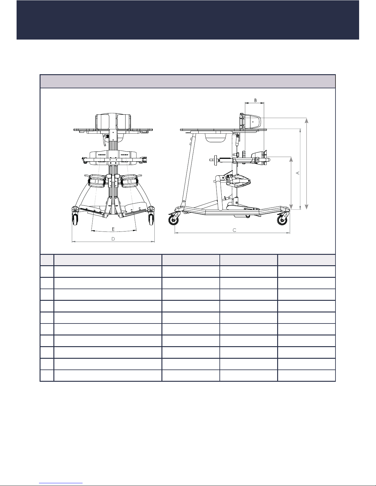
5. Technical data
6. Guarantee
The two-year statutory guarantee period shall apply for all products. This guarantee
period shall begin with the delivery or handover of the goods. Should a veri able
material or manufacturing fault occur within this time period, we shall, after carriage
paid return to us, view the indicated damage and, if applicable, either repair or deliver a new product at our discretion.
Dimensions - basic model
F
G
Size 1 Size 2 Size 3
Body size 75 -110 cm 100 - 140 cm 120 - 160 cm
A Height from foot plate to tray 48,5 - 80,5 cm 71 - 95 cm 80 - 112 cm
B Pelvis depth 12 - 22 cm 16 - 28 cm 20 - 35 cm
Depth adjustment of pelvis frame (via crank) 6 cm 6 cm 6 cm
C Total length 84 cm 90 cm 100 cm
D Total width 57 cm 65 cm 71 cm
E Abduction divided foot plate 0° - 27° 0° - 27° 0° - 27°
F Pelvis height 45 - 60 cm 57 - 80 cm 65 - 90 cm
G Sternum height 55 - 85 cm 75 - 110 cm 95 - 125 cm
Max. load 40 kg 60 kg 80 kg
Page 23
23
7. Identication
7.1 EC declaration of conformity
Company Schuchmann GmbH & Co.KG
Dütestr. 3
D-49205 Hasbergen
Tel.: +49 (0) 54 05 / 909 - 0
Fax: +49 (0) 54 05 / 909 - 109
declares on their sole responsibility that the product named below is classi-
ed as product class 1
"TIM" - the angular-adjustable upright trainer
Art. No.: 48 01 100 (Size 1) 48 02 100 (Size 2) 48 03 100 (Size 3)
the relevant regulations of the guidelines and standards listed below:
• EC Directive 93/42/EEC on medical products from 14th June 1993
• DIN EN 12182 Technical aids for the disabled
• EN ISO 14971 Medical products - Application of risk management
on medical products
This declaration of conformity applies only for products with the article
numbers stated above and is valid until 31.12.2019.
Date 27.08.2014
Signature ________________________
Name Torsten Schuchmann
Role Safety Representative for Medical Products
Page 24
24
This product has been delivered by the following specialist dealer:
7.3 Product version
The TIM upright trainer is available in three sizes and can be supplemented through
a diverse range of accessories (see Point 2.6).
7.4 Issue of the document
Instructions for use TIM - Change status G; Issue 11.2017
7.5 Name and address of the manufacturer, specialist dealer supplying the
product
This product was manufactured by:
Schuchmann GmbH & Co. KG
Dütestraße 3 · 49205 Hasbergen
Tel. +49 (0)5405/909-0 · Fax +49 (0)5405/909-109
[email protected] · www.schuchmann-reha.de
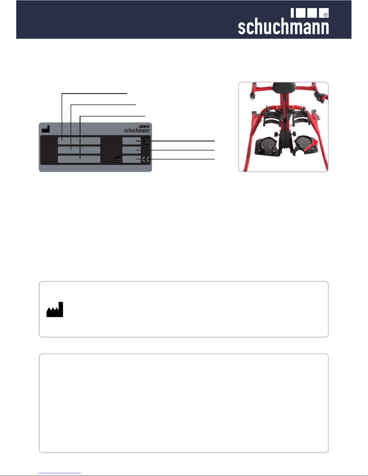
7.2 Serial number / date of manufacture
The serial number, the date of manufacture and other information can be found on
the type plate, which is located on all of our products (A).
Schuchmann GmbH & Co. KG
Dütestr. 3 · 49205 Hasbergen · Germany
www.schuchmann-reha.de · [email protected] · Fon +49 (0) 5405 / 909 - 0
Typ
Product
SN
Max. load
Size
Size
Max. load
Date of manufacture
Part number
Product name
Serial number
A
 Loading...