

Page 1
User Manual
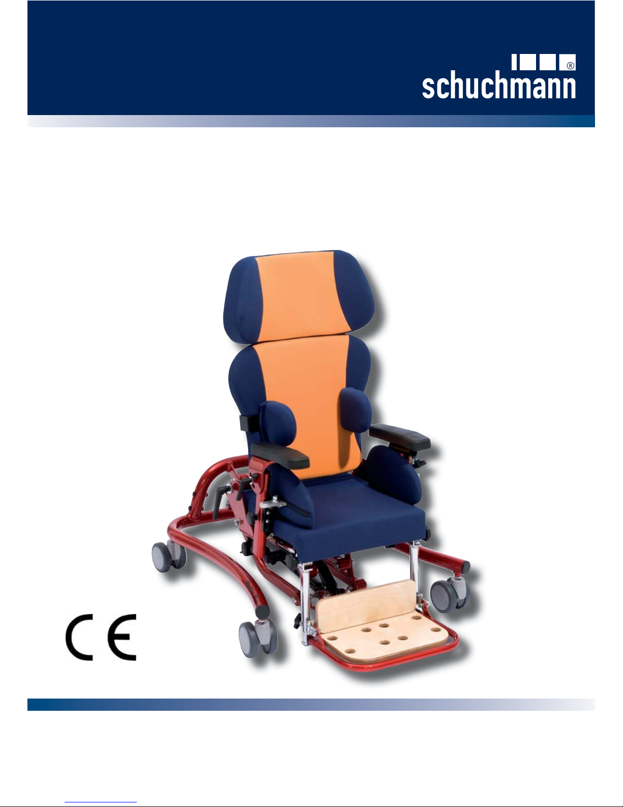
MADITA-FUN
Posture Chair
Page 2

Dear Customer,
ank you for purchasing the Madita Fun Posture Chair. We advise you to
read through this manual carefully before attempting to use the chair.
(We reserve the right to make technical alterations at any time)
Please also make sure that each person and any carer who uses the chair is
also aware of the contents in this manual and follows the instructions each
time they use the product.
Please retain these instructions with the product, keeping them safely for
future reference. We advise you to make a photocopy in case they become
lost or ask us for a further copy.
Yours faithfully,
Schuchmann Team
Page 3

Contents Page
1. General Information 2
2. Overview / component parts 2
3. Operation of the standard product
3.1 Locking the castors 3
3.2 Seat height 3
3.3 Seat angle 4
3.4 Inclined back rest 4
3.5 Seat depth 4
3.6 Back rest height 5
3.7 Knee angle 5
3.8 Foot support height 5
3.9 Arm rests 6
4. Use of the accessories
4.1 Head Support 6
4.2 Side bolsters 7
4.3 Side bolster additional info 7
4.4 Hip bolsters (seat width) 7
4.5 Tab le 8
4.6 Knee abduction wedge 8
5. Cleaning and maintenance 9
6. Technical data 9
7. Guarantee details 9
Contents
Contents
1MADITA-FUN - Modi cation status C - Issued 11.2010
Page 4
1. General information
e Madita Fun Posture Chair is intended for use by children and young
persons who are unable to sit or stand unaided.
Attention:
e product must not be used without supervision
e product must only be used on even or solid ground
e product must not be used to transport people
In order to assist with the transfer of the user into and out of the product, the Carer
must stand at the side of the chair and hold the seat support. is ensures that all
moving parts e.g. height adjustment remains unaltered.
2. Overview / component parts
Important information!
When adjusting the locking screws or nuts, please use the hexagonal key or spanner
supplied with the chair. ese should be located with the user manual attached to the
back of the chair.
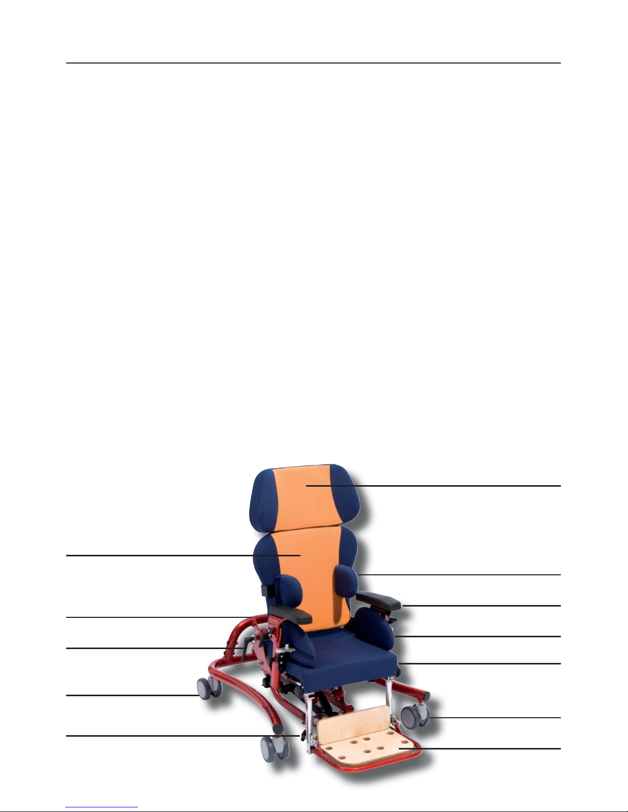
An example of the Madita Fun Posture Chair:
General Information / Overview
General Information / Overview
2
Back Rest
Backrest Angle Adjustment
Rear Castors
with Brakes
Head Support
Side Bolsters
Arm Rests
Hip Bolsters
Seat
Foot Support
Front Castor
Base Frame
Foot Pedel for
Height Adjustment
Page 5
Operation of the standard product
Operation of the standard product
3
3.1 Locking the castors
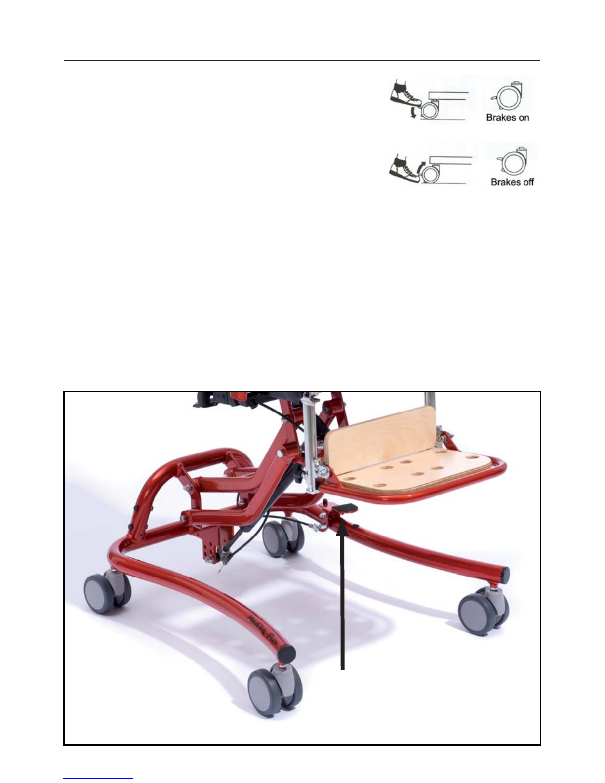
e Posture Chair is parked by locking the two rear castors.
Foot operation of the brakes:
Releasing the brakes:
Warning: e brakes only operate correctly on even surfaces!
3.2 Seat height adjustment
Seat height adjustment is assisted by a gas spring. To raise the seat height, operate the foot
pedal (arrowed). With slight assistance, the seat will raise. To lower the seat, depress the
pedal and at the same time push down on the seat.
e foot pedal can also be locked in position, to prevent unwanted movement, by means of
the locking pin which is to be found on the inner side of the foot pedal. Turn the locking
pin until it engages (slight movement of the foot pedal will help it to engage). To unlock
the pin, pull it outwards and turn through a quarter turn.
Page 6
Operation of the standard product
Operation of the standard product
4
3.3 Seat angle adjustment
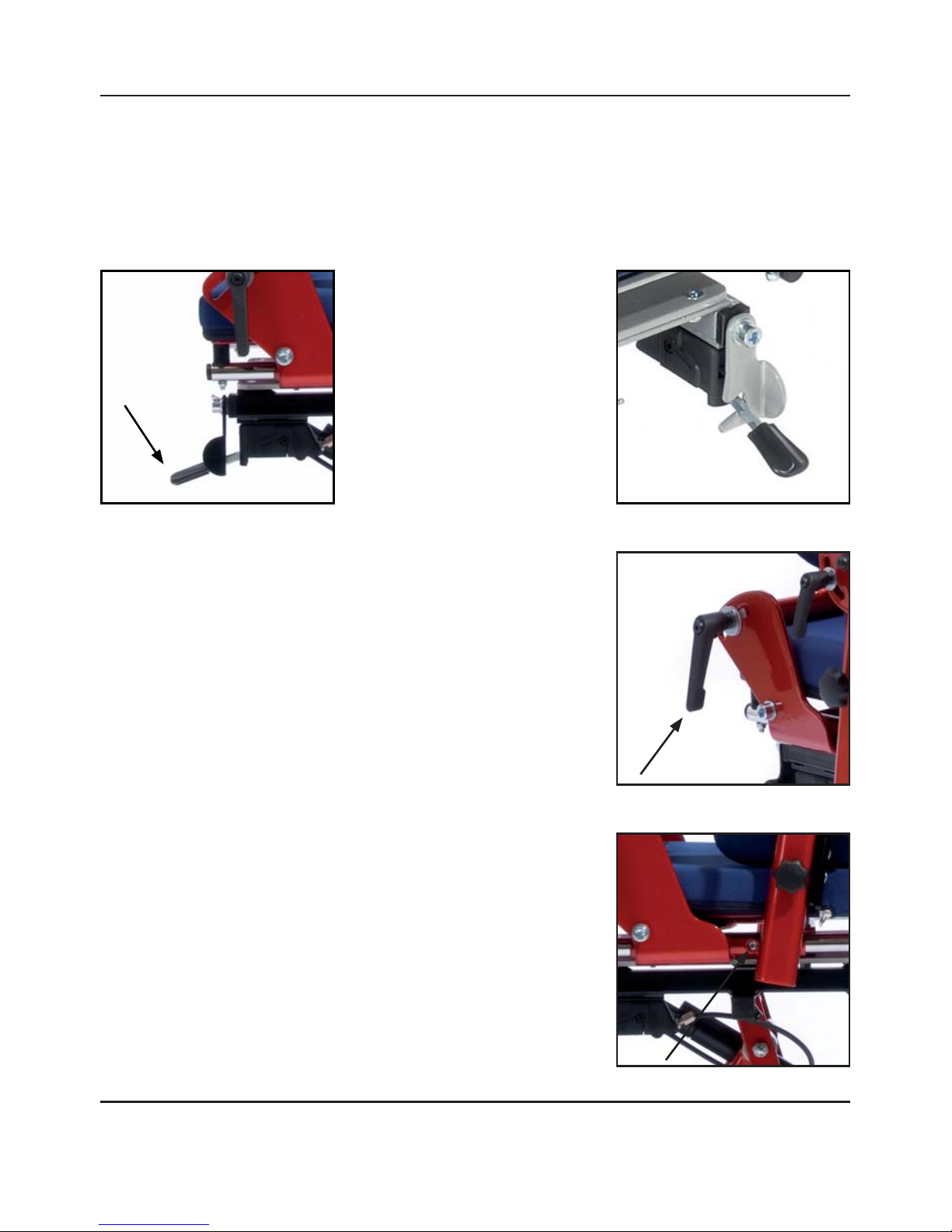
In order to adjust the seat angle, the hand release lever should be pushed downwards. e
seat unit can then be moved into the ‘Active’ or ‘Passive’ position. e locking bracket
should be hinged down to avoid the lever being unintentionally adjusted when in use.
Hand Release Lever:
Caution!
A er making all adjustments, tighten all the screws rmly again!
3.4 Inclined back rest
e angle of the back rest can be adjusted by operating the
clamp handle (see arrow).
When adjusted, retighten the clamp handle.
3.5 Seat Depth
Adjustment of the seat depth is done by loosening the two
socket head bolts (see arrow) which are on the side of the
chair. When the seat is in the desired position, the bolts
should be retightened.
Page 7
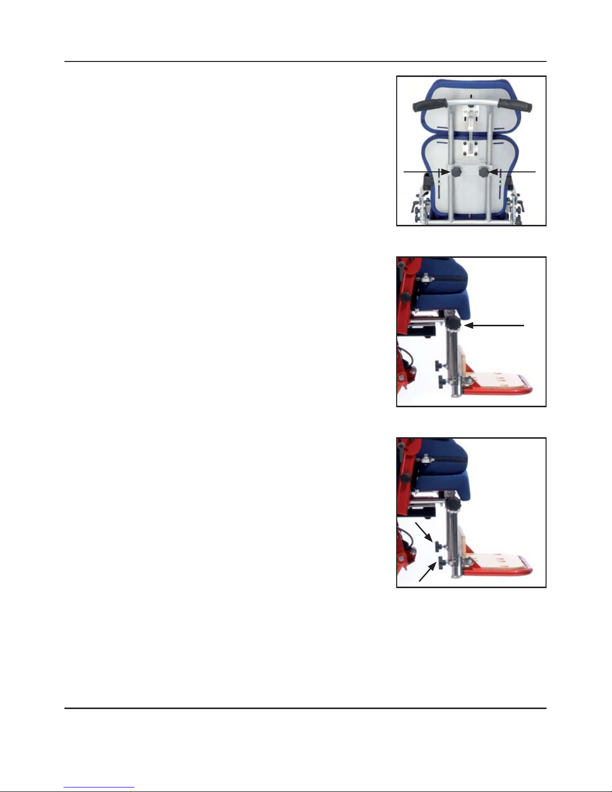
3.6 Back rest height
To adjust the height of the back rest, the two locking wheels
behind the back rest (see arrows) should be loosened.
When the back rest is in the desired position, the locking
wheels should be retightened.
Operation of the standard product
Operation of the standard product
5
Caution!
A er making all adjustments, tighten all the screws rmly again!
3.7 Knee angle adjustment
e knee angle adjustment has a ratchet mechanism which
allows for adjustment in small steps. To adjust the angle, both
locking wheels (see arrow) must be loosened.
When the required position is achieved, the locking wheels
should be retightened.
3.8 Foot support height
e foot support height can be adjusted. To do this, loosen
both socket head screws (see arrows) on the rear side of the
foot support.
When the required position is reached, the screws should be
retightened.
On delivery, size 0 has a lower leg length adjustment rage from 20 cm to 24 cm.
To get a lower leg length from 15 cm to 20 cm, the innertubes have to be trimed.
To do that, the setscrew must be loosened and both press bottons have to be pushed.
Now the foot rest can be removed and the inner tubes of the lower foot rest part must be
trimed 4 cm. Insert the press buttons in the innertubes and reassemble the foot rest.
Page 8
Operation of the standard product / Use of accessories
Operation of the standard product / Use of accessories
6
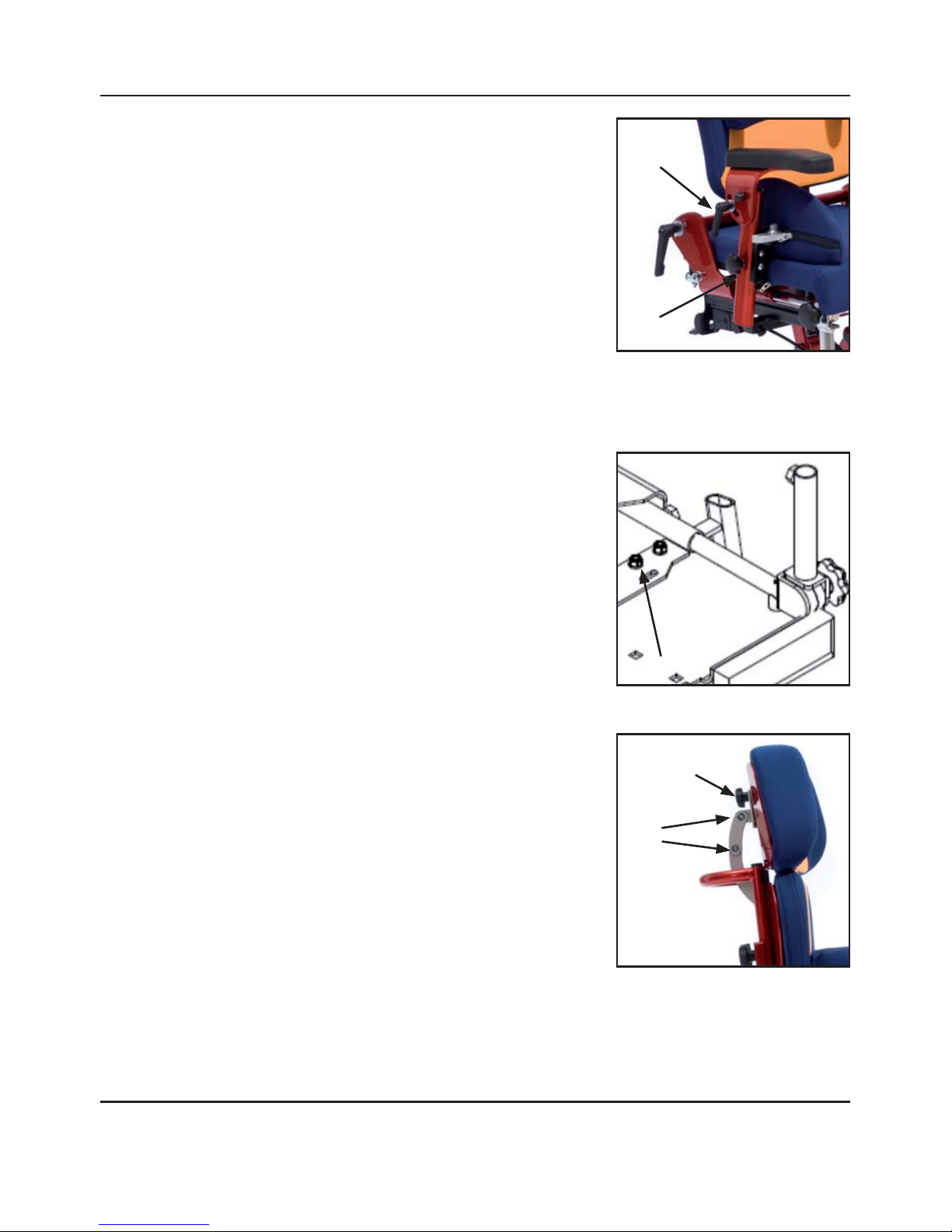
3.9 Arm rests
Arm rest height adjustment
e two arm rests are adjusted by loosening the locking
wheels (B) on the arm rests le and right.
When in the required position, the locking wheels should be
retightened.
A
B
Caution!
A er making all adjustments, tighten all the screws rmly again!
C
Arm rest angle adjustment
e angle of the arm rests can be adjusted. is is very useful when a table is being used.
To adjust the angle, loosen the top locking handle (A) at the side of the arm rest.
When in the required position, retighten the locking wheel.
Arm rest width adjustment
e width adjustment is done by loosening
the locking nuts (C) which can be
found underneath the seat surface.
When in the required position, the locking
nuts should be retightened.
4. Use of accessories
4.1 Head Support
e angle and height of the head rest can be adjusted.
To make the adjustment, loosen the bolts (B) in the
articulated arms of the head support holder. When
adjustment is complete, retighten the bolts. To adjust
the height, loosen the two locking wheels (A).
When adjustment is complete, retighten the wheels.
B
A
Page 9
Use of accessories
Use of accessories
7
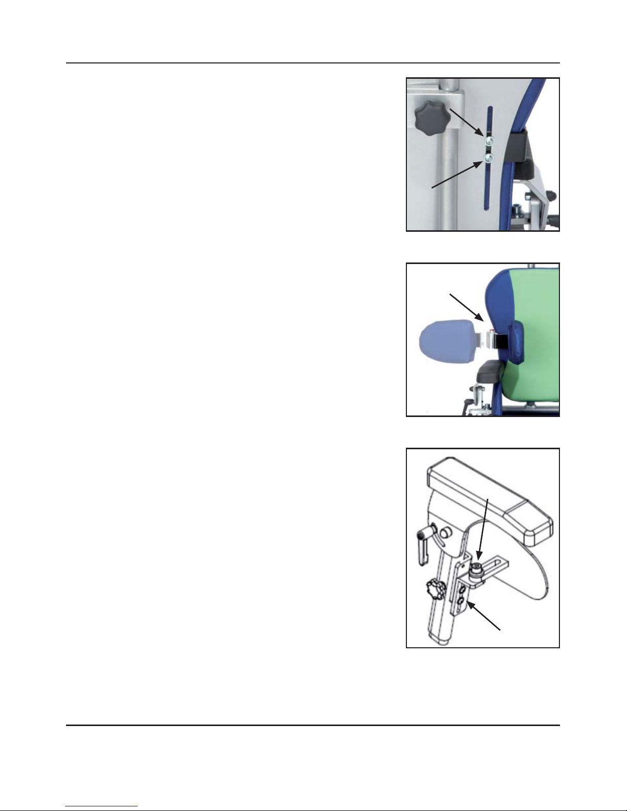
4.2 Side bolsters
To adjust the width, loosen and remove the two nuts
(see arrows) on the back of the back rest. e height is
adjusted by loosening the nuts and bolts at the required
height in the slotted holes (see arrows) in the backrest plate.
Caution!
A er making all adjustments, tighten all the screws rmly again!
4.3 Lateral foldable Side bolsters
To fold the side bolster laterally, the red press button on the
top side of the link, must be pushed. Now the side bolster
can be pivoted laterally.
4.4 Hip bolsters (seat width)
Width / angle adjustment (seat width)
A er loosening the cylindrical head bolts (A), the
angle and width of the hip bolster can be adjusted
(seat width).
Height adjustment
e height of the bolsters is adjusted by loosening the two
bolts (B). When adjustment is complete, the bolts should
be retightened.
B
A
Page 10
Use of accessories
Use of accessories
8
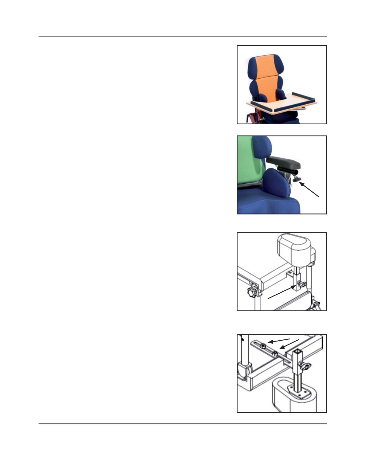
4.5 Use of table
Table height
is is adjusted by means of the arm rests.
Depth adjustment
To alter the distance of the table form the user, the winged
locking nuts (see arrow) should be loosened.
Retighten the wing nuts a er adjustment.
Folding
To fold the table, for example when the user is being
positioned in the chair, it is simply folded upwards,
to one side.
4.6 Knee abduction wedge
Height adjustment
e height is adjusted by loosening the wing nut (see arrow)
on the abduction wedge. e wing should be retightened
following adjustment.
Depth adjustment
e depth is adjusted by loosening the nuts (see arrows)
which are found under the seat.
Retighten the two nuts following adjustment.
Caution!
A er making all adjustments, tighten all the screws rmly again!
Page 11
Cleaning and maintenance / Technical Data / Guarantee
Cleaning and maintenance / Technical Data / Guarantee
9
Dimensions in cm Gr. 0 Gr. 1 Gr. 2
Seat depth 15 - 24 21 - 30 30 – 42
Seat width 16 - 30 16 - 30 26 - 38
Height of low backrest 30 30 40
Height of high backrest 38 38 48
Max. adjustable backrest height 45 45 55
Seat height 25 - 60 25 - 60 25 - 60
Lower leg length 15 - 24 21 - 31 28 - 45
Total witdh 565666
Total length 65 65 75
Seat angle (-) 8° - 30° (-) 8° - 30° (-) 8° - 30°
Backrest angle (-) 5° - 25° (-) 5° - 25° (-) 5° - 25°
Max. load (kg) 30 30 50
Weight of chair (kg) 20 20 24
Castors:
2 x double castors
2 x locking double castors
5. Cleaning and maintenance
e Posture Chair is designed to be relatively maintenance free. All parts are corrosion
resistant. However under unfavourable conditions some slight rusting may occur. If this
happens, it can be easily removed by simply wiping with polish and a so cloth.
It is recommended that following a long period of use, all nuts and bolts are checked for
tightness. Like every technical product, the chair requires regular inspection. Check the
unit frequently for tears, breakage, holes or lost parts and/or non functioning parts.
Remove the chair form normal use when it is clear it is not functioning correctly or safely.
6. Technical Data
7. Guarantee
e Madita Fun Posture Chair, with its’ accessories, are guaranteed in the UK for a period
of 12 months from the date of delivery against defects arising from faulty material, inferior
workmanship or construction.
e result of incorrect handling of the unit shall not be covered by the guarantee.
In line with the company’s policy of continual product improvement, we reserve the right
to carry out improvements to the speci cation without notice.
is product conforms to the following guideline:
93/42/EWG for medical products
Page 12

schuchmann GmbH & Co. KG
Dütestraße 3 · 49205 Hasbergen · Fon +49 (0)5405/909-0 · Fax +49 (0)5405/909-109
[email protected] · www.schuchmann-reha.de
Distributor:
Serial number:
 Loading...