

SCHOLTES BC 99DT P XA,BC 99D P XA,BCG 99D P,SV70DPNAX,SV70SPNAB,SV70DPNAB,SV70SPNAX Operating Instructions Manual
BC 99DT P XA
BC 99D P XA
BCG 99D P
Contents
Installation, 18-19
Positioning
Electrical connection
Technical data
Description of the appliance, 20
Overall view
Control panel
Display
Oven structure, 21
Start-up and use, 22-28
Setting the clock
Setting the minute minder
ExtraLarge Space
Small Space
Main Space
Using the Small Space and Main Space at the same
time
Programming cooking
Practical cooking advice
Cooking advice table for the ExtraLarge Space
feature
Cooking advice table for the Small Space feature
Cooking advice table for the Main Space feature
Cooking advice table for using the Small Space and
Main Space at the same time
Precautions and tips, 29
General safety
Disposal
Respecting and conserving the environment
Care and maintenance, 30-31
Switching the appliance off
Cleaning the appliance
Cleaning the oven door
Replacing the light bulb
Assistance
Automatic cleaning using the PYROLYTIC function
Operating Instructions
OVEN
GB
Italiano, 1 Français, 32
Espanol, 47
English,17
IT
GB
FR
ES
GB
18
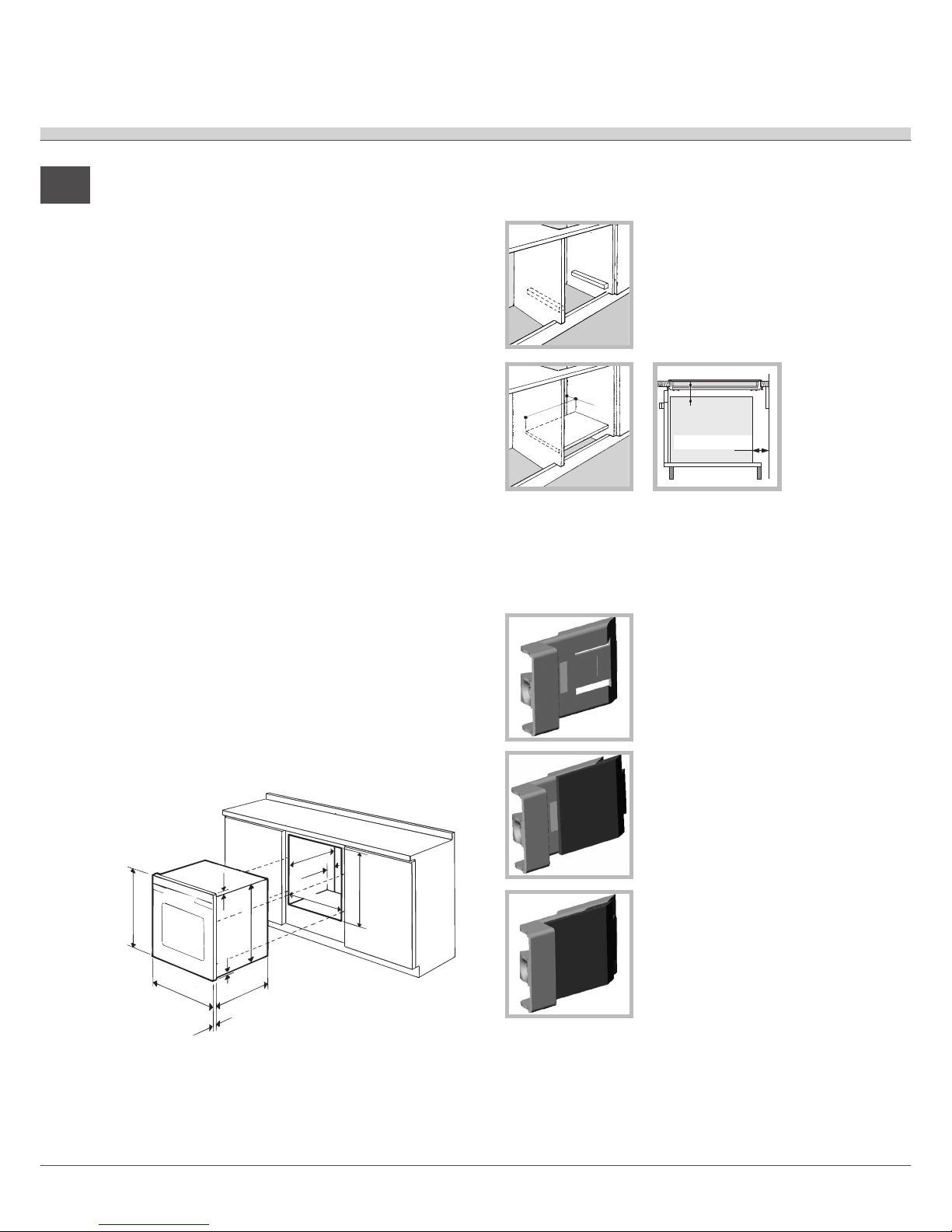
Ventilation
To ensure adequate ventilation is provided, the back
panel of the cabinet must be
removed. It is advisable to
install the oven so that it rests
on two strips of wood, or on a
completely flat surface with an
opening of at least 45 x 560
mm (
see figures
).
Centring and fixing
Position the 4 tabs on the side of the oven so that
they are aligned with the 4 holes on the outer frame.
Adjust the tabs in accordance with the thickness of
the cabinet side panel, as shown below:
20 mm thick: take off the
removable part of the tab (
see
diagram
);
18 mm thick: use the first
groove, which has already
been set in the factory (
see
diagram
);
16 mm thick: use the second
groove (
see diagram
).
Secure the appliance to the
cabinet by opening the oven door and inserting 4
screws into the 4 holes on the outer frame.
!!
!!
! All parts which ensure the safe operation of the
appliance must not be removable without the aid of
a tool.
!!
!!
! Please keep this instruction booklet in a safe place
for future reference. If the appliance is sold, given
away or moved, please make sure the booklet is
also passed on to the new owners so that they may
benefit from the advice contained within it.
! Please read this manual carefully: it contains
important information concerning the safe operation,
installation and maintenance of the appliance.
Positioning
!!
!!
! Do not let children play with the packaging
material; it should be disposed of in accordance
with local separated waste collection standards (
see
Precautions and tips
).
!!
!!
! The appliance must be installed by a qualified
professional in accordance with the instructions
provided. Incorrect installation may damage
property or cause harm to people or animals.
Built-in appliance
Use a suitable cabinet to ensure that the appliance
functions properly:
• the panels adjacent to the oven must be made of
heat-resistant material;
• cabinets with a veneer exterior must be
assembled with glues which can withstand
temperatures of up to 100°C;
• to install the oven under the counter (
see diagram
)
or in a kitchen unit, the cabinet must have the
following dimensions:
!!
!!
! The appliance must not come into contact with
electrical parts once it has been installed.
The indications for consumption given on the data
plate have been calculated for this type of
installation.
595 mm.
595 mm.
24 mm.
545 mm.
5 mm.
576 mm.
23 mm.
593 mm.
45 mm.
558 mm.
547 mm. m
in.
Installation
560 mm.
45 mm.
min. 20 mm
min. 45 mm
FORNO
VENTILATO
19
GB
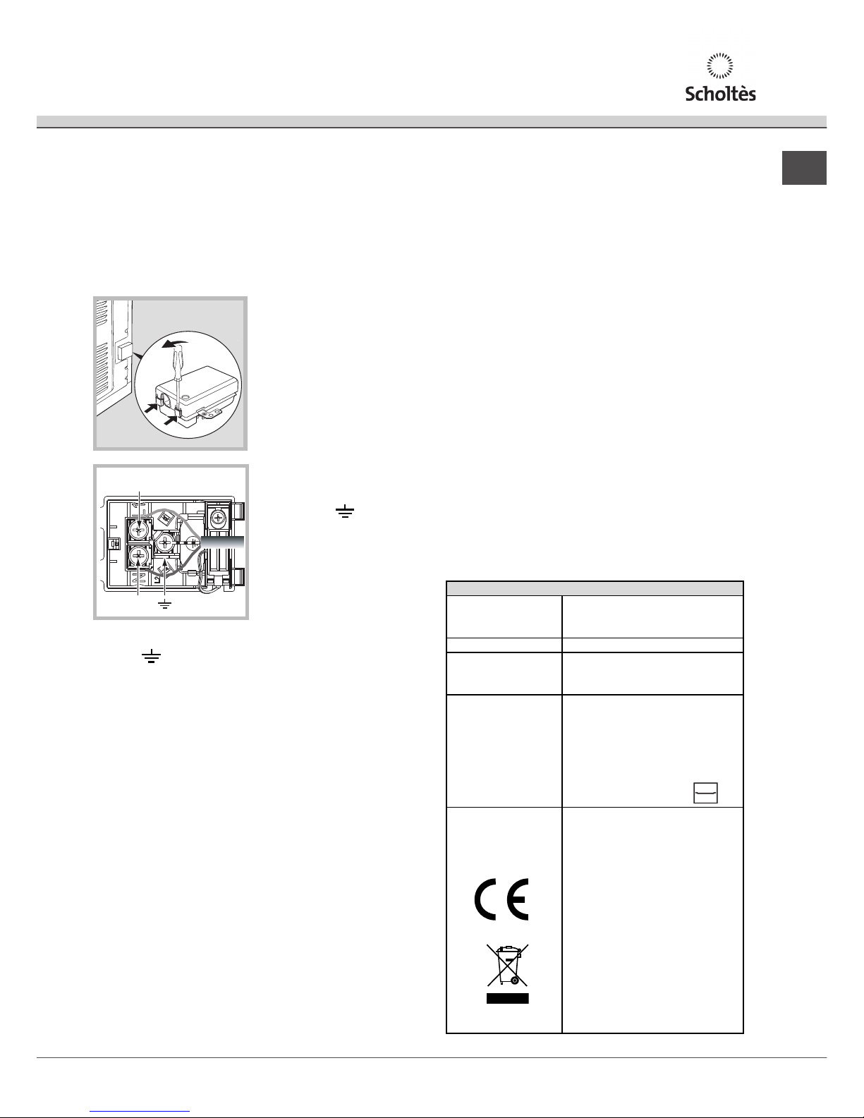
Electrical connection
!!
!!
! Ovens equipped with a three-pole power supply
cable are designed to operate with alternating
current at the voltage and frequency indicated on
the data plate located on the appliance (
see below
).
Fitting the power supply cable
1. Open the terminal
board by inserting a
screwdriver into the
side tabs of the cover.
Use the screwdriver as
a lever by pushing it
down to open the cover
(
see diagram
).
2. Install the power
supply cable by
loosening the cable
clamp screw and the
three wire contact
screws L-N-
.
Connect the wires to
the corresponding
terminals: the Blue wire
to the terminal marked
(N), the Brown wire to
the terminal marked (L)
and the Yellow/Green
wire to the terminal
marked
(
see diagram
).
3. Fix the cable in place by fastening the clamp
screw.
4. Close the cover of the terminal board.
Connecting the electricity supply cable to the
mains
Install a standardised plug corresponding to the
load indicated on the data plate (
see table
).
The appliance must be directly connected to the
mains using an omnipolar switch with a minimum
contact opening of 3 mm installed between the
appliance and the mains. The switch must be
suitable for the charge indicated and must comply
with current electrical regulations (the earthing wire
must not be interrupted by the switch). The supply
cable must be positioned so that it does not come
into contact with temperatures higher than 50°C at
any point.
!!
!!
! The installer must ensure that the correct electrical
connection has been performed and that it is fully
compliant with safety regulations.
Before connecting the appliance to the power
supply, make sure that:
• the appliance is earthed and the plug is compliant
with the law;
• the socket can withstand the maximum power of
the appliance, which is indicated on the data
plate (
see below
);
• the voltage is in the range between the values
indicated on the data plate (
see below
);
• the socket is compatible with the plug of the
appliance. If the socket is incompatible with the
plug, ask an authorised technician to replace it.
Do not use extension cords or multiple sockets.
!!
!!
! Once the appliance has been installed, the power
supply cable and the electrical socket must be
easily accessible.
!!
!!
! The cable must not be bent or compressed.
!!
!!
! The cable must be checked regularly and replaced
by authorised technicians only (
see Assistance
).
!!
!!
!
The manufacturer declines any liability shouldThe manufacturer declines any liability should
The manufacturer declines any liability shouldThe manufacturer declines any liability should
The manufacturer declines any liability should
these safety measures not be observed.these safety measures not be observed.
these safety measures not be observed.these safety measures not be observed.
these safety measures not be observed.
N
L
APPLI ANCE SPECIFICATION S
Dimensions
width 43.4 cm
height 39 .5 cm
depth 40.8 cm
V
olume 70 l
Electrical
connections
volt age: 220 - 240 V~ 50 Hz
maximum power absorbed
3400 W (see data plate)
ENERGY LABEL
Directive 2002/40/EC on the
label of electric ovens .
Standard EN 50304
Decl ared e nergy consumption
fo r Forced convection
Class – hea ti ng mode:
Conventional oven.
Thi s appl ianc e conf orms to t he
fo llowi ng Eur opean Econo mic
Community directives:
2006/95/EEC dated 12/12/06
(Low Voltage) and subsequent
amendm ents – 2004/108/ EEC
dated 15/12/04
(Elec troma gnetic
Compat ibility ) and subsequent
amendm ents - 93/68/EEC
dated 22/07/93 and
subsequent amendments.
2002/96/EEC and subs equent
amendm ents.
1275/2008 Stand-by/off
mode
GB
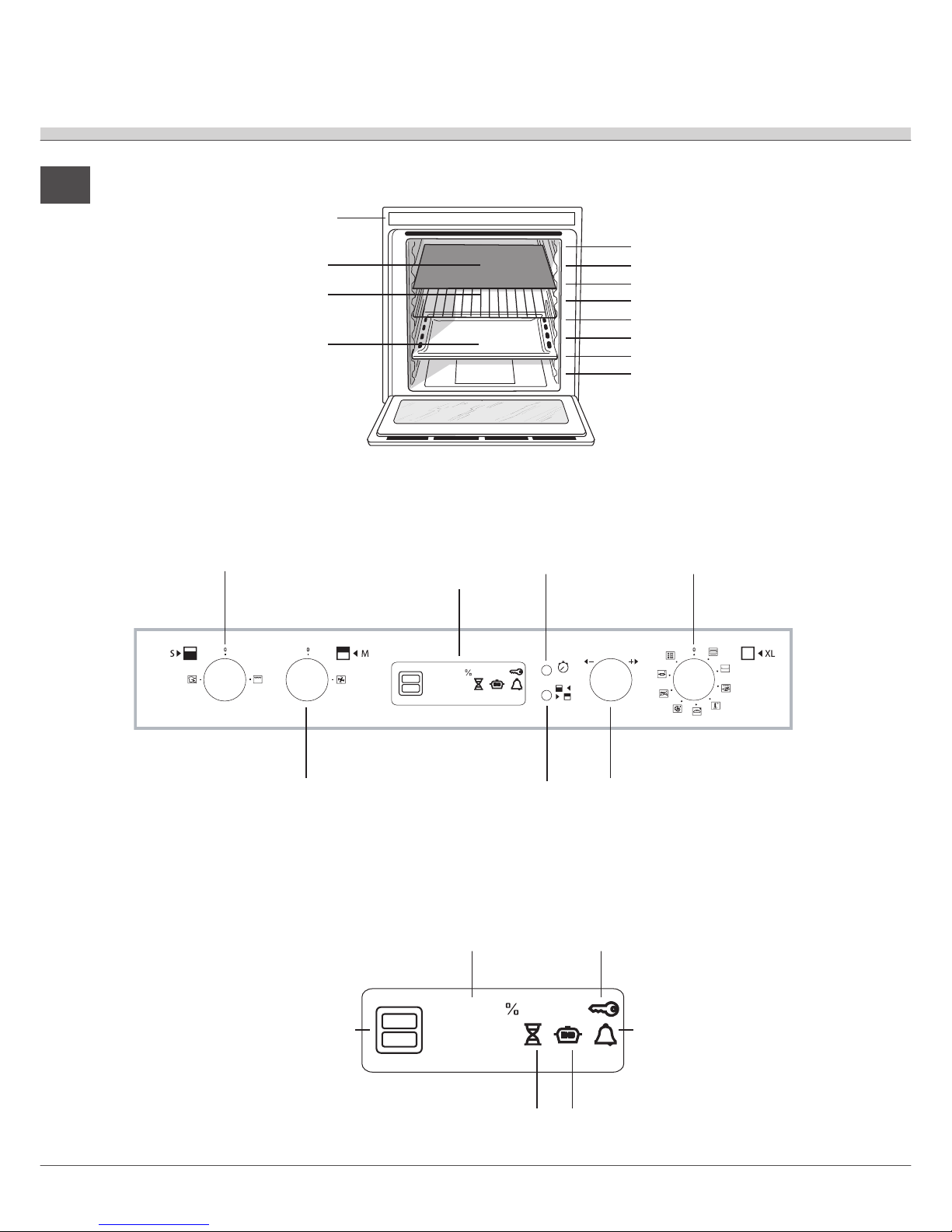
20
Control panel
RACK shelf
DRIPPING PAN shelf
GUIDE RAILS
for the sliding racks
position 5
position 4
position 3
position 7
position 6
Divider "D" position
position 2
position 1
DIVIDER shelf
Description of
the appliance
Overall view
Control panel
Display
¡•OC
•• ••
:
EXTRALARGE
SPACE FUNCTION
knob
SET
TEMPERATURE/TIMER
knob
DISPLAY
SET TIMER
button
SELECT RECESS
button
MAIN SPACE
FUNCTION
knob
SMALL SPACE
FUNCTION
knob
¡•OC
•• ••
:
TEMPERATURE and
TIME numerical digits
END OF COOKING
icon
DURATION
icon
TIMER icon
RECESS
SELECTED
icon
DOOR LOCK
icon
21
GB
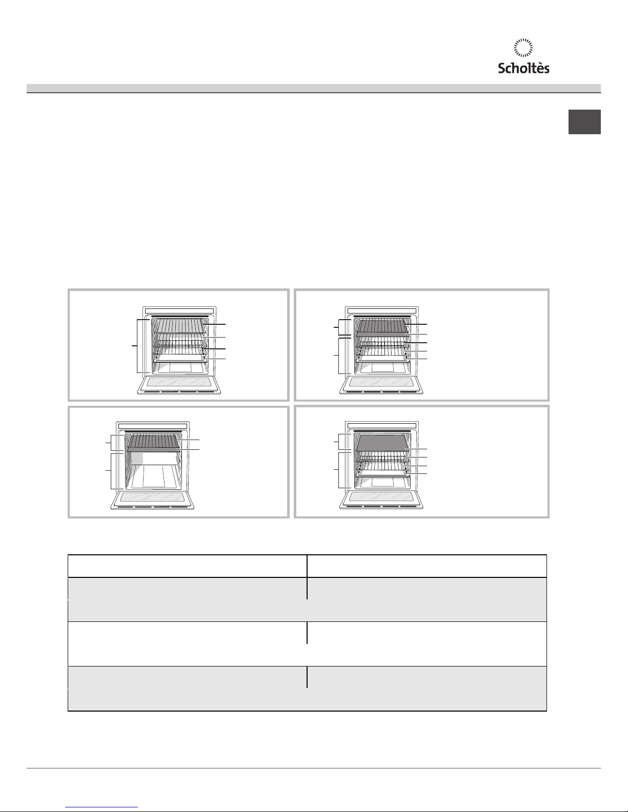
Oven structure
RACK
DRIPPING PAN
RACK
RACK
EXTRALARGE
SPACE
ExtraLarge Space: cooking on 4 shelf levels
RACK or DRIPPING PAN
DRIPPING PAN
(cooking on 3 shelves)
Divider "D" (fixed position)
RACK (cooking on 3 shelves)
RACK (cooking on 3 shelves)
SMALL
SPACE
MAIN
SPACE
DRIPPING PAN
(cooking on 3 shelves)
Divider "D" (fixed position)
RACK (cooking on 3 shelves)
RACK (cooking on 3 shelves)
SMALL
SPACE
MAIN
SPACE
Main and Small Space: simultaneous operation
RACK or DRIPPING PAN
Divider "D"
(fixed position)
SMALL
SPACE
MAIN
SPACE
Cooking using the Small Space only
Cooking using the Main Space only: cooking on 3 shelf levels
The table below lists the possible temperature
values which may be set. The intelligent display will
The oven has a capacity of 70 litres and offers users
the option of cooking on 4 shelves at the same time or
cooking large quantities, which would not necessarily
be possible in a traditional oven.
Thanks to the ExtraLarge Space, oven offers 10 cooking
functions, 6 of which are universal (Creation) and
suitable for any type of cooking, while the remaining 4
are automatic (Success) programmes which can be
used to achieve perfect results for any recipe.
The oven also offers maximum comfort for all
requirements, with 4 different operating options: the
oven is one large compartment but can be divided into
separate spaces of various sizes, each with its own
independent temperature and duration controls.
This is made possible thanks to the heat-insulating
DIVIDER, which divides the whole ExtraLarge Space
into two different-sized spaces: the Main Space and
the Small Space.
The Main and Small Space compartments may be
used at the same time to cook different dishes more
quickly, or they may be used separately so that only
the space necessary is used.
When the two compartments are used at the same
time, the cooking temperature of each may be
adjusted to a value between 50° and 250°. There may
be a difference in temperature of 100° between the two
zones, which means it is possible to cook very
different dishes without any flavours or aromas
intermingling.
guide you through the correct procedure used to
adjust the temperature of the two cavities.
To cancel any of the settings, simply turn the Small Space or Main Space function knob to the “0”
position.
Tem pera ture in the fir st ca vit y
(Main or Small Space)
Temperature in the second cavity
(Small or Main Space)
Between 40°C and 150 °C The t emperature difference in relat ion to the first recess
selected is no greater than 5 0°C
For example: if you set one recess to 90°C,
y
ou may set a value of between 40°C (90°C-50°C) and 140°C (90°C+50°C) for the other .
Between 15 5°C and 20 0°C The t emperature difference in relat ion to the first recess
selected is no greater than 7 0°C
For example: i f you set one recess to 180°C,
you may s et a value of b etween 110°C (180°C-70°C ) and 250°C (180°C+7 0°C) f or the other.
Between 20 5°C and 30 0°C The t emperature dif fer ence in relat ion to the first recess
sel ected is no greater than 100°C
For example: i f you set one recess to 210°C,
you m ay s et a value of between 11 0°C (210°C-100°C) and 300° C (max imum t emperature set tin g) for th e other.
 Loading...