

Page 1

UMS 20
Universal-Mikrofonschiene
Universal Stereo Microphone Bracket
Bedienungsanleitung
User Guide
- page 10
Inhaltsverzeichnis Seite
Allgemeines 2
Übersicht Aufnahmetechniken 3
XY-Stereo 4
ORTF-Stereo 5
Variationen mit Nieren 6
MS-Stereo 7
Blumlein-Stereo 8
Table of Contents page
Preface 10
Survey of the Recording Techniques 11
X/Y Stereo 12
ORTF Stereo 13
Variants with Cardioids 14
M/S Stereo 15
Blumlein Stereo 16
Page 2

SCHOEPS GmbH · Spitalstr. 20 · D-76227 Karlsruhe (Durlach) · Tel: +49 721 943 20-0 · Fax: +49 721 943 2050
www.schoeps.de · [email protected]
Allgemeines
2
Deutsch
Die UMS 20 ist eine kleine Schiene für Mikro fone mit 20mm Durchmesser, insbesondere
für SCHOEPS-Mikrofone der modularen Serie
“Colette”. Mit ihr sind die links abgebildeten
Stereo-Auf nah meverfahren realisierbar.
Die UMS 20 sollte mit der Stativklammer
SG 20 oder der elastischen Aufhängung A 20 S
verwendet werden (beide sind separat zu bestellen). Hier durch kann sie geneigt werden. Bei
der A 20 S können die Kabel in den Kabel haltern fest geklemmt und dadurch zugentlastet
werden.
Die Montage der UMS 20 auf einem Stativ
erfolgt stets über den mitgelieferten 20mmZylinder (siehe Abb. 6 unten), der je nach Auf nahme ver fah ren auf den Gewindezapfen in
der Schienen mitte oder an deren Ende aufgeschraubt wird.
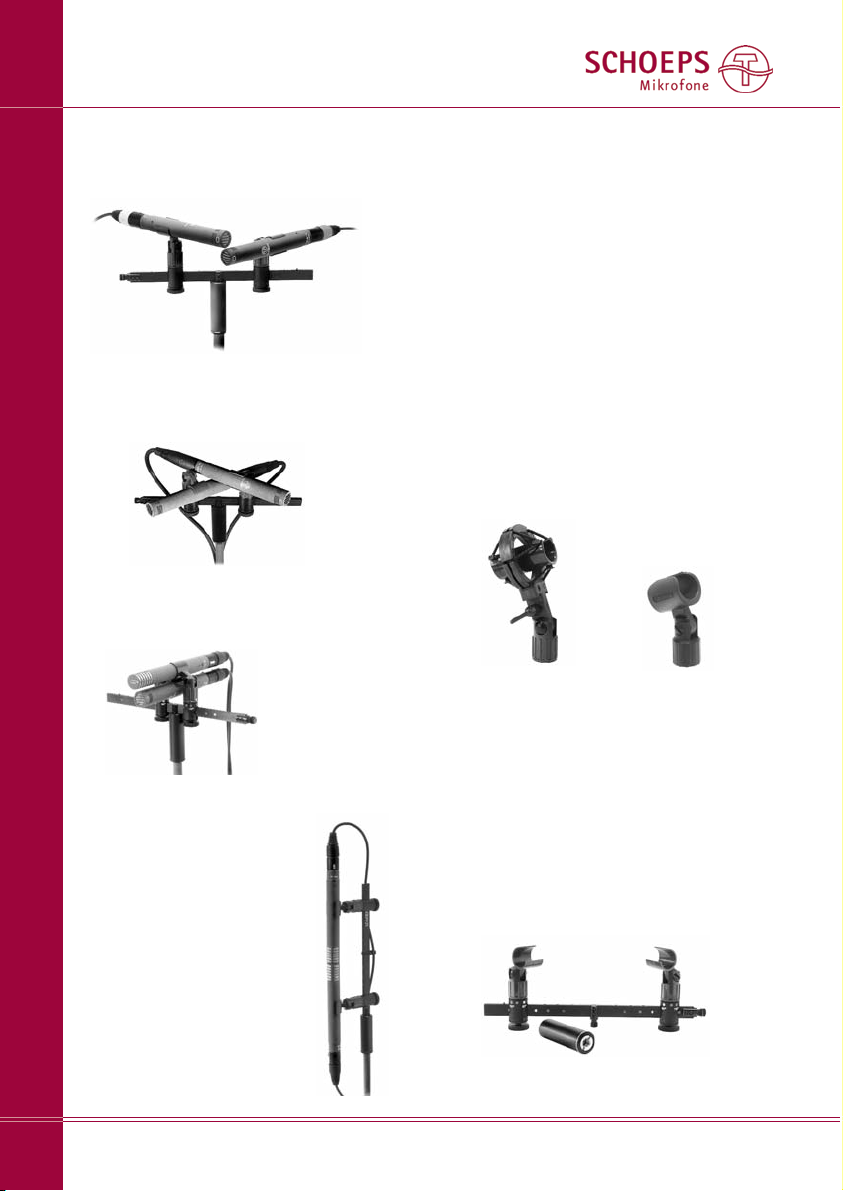
Abb. 1
XY, hier mit 90° und axial besprochenen Mikro fo nen; die gelben Markierungen erleichtern das
Einstellen der Klammer-Positionen
Abb. 3
MS mit Mikrofonen für axiale Einsprache;
(blaue Markierungen)
Abb. 2
ORTF, Kapselabstand: 17cm, Winkel: 110°;
(grüne Markierungen)
Abb. 4
Blumlein, XY, MS mit Mikrofonen
für seitliche Einsprache;
(rote Markierungen)
Abb. 6
Abb. 5 A 20 S SG 20
Dieser Zylinder hat ein 5/8"-27 NS-Innen gewinde, in dem sich ein Adapter für 3/8"
und 1/2"-Gewin de befindet.
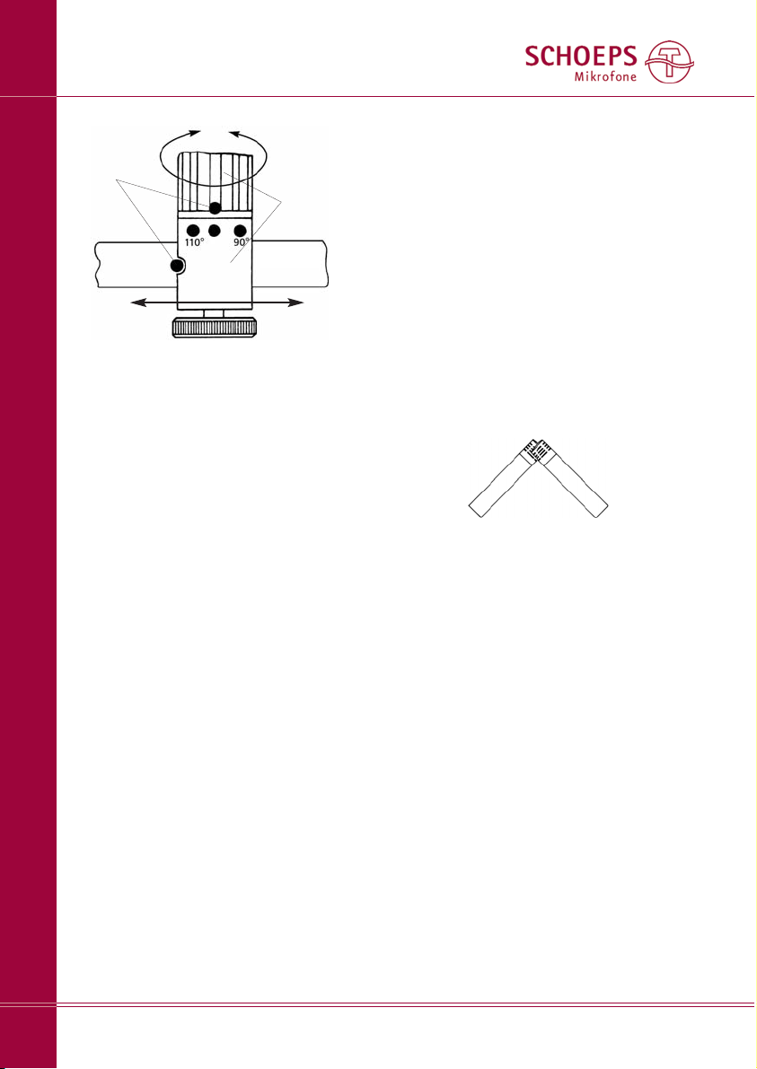
Die Reiter auf der Schiene und auch die drehbaren Klammern rasten in vier definierten, durch
Farb punkte markierte Stellungen ein. Jede Farbe
ist einem bestimmten Auf nahme verfahren
zugeordnet.
UMS 20 Universal-Mikrofonschiene
Page 3

SCHOEPS GmbH · Spitalstr. 20 · D-76227 Karlsruhe (Durlach) · Tel: +49 721 943 20-0 · Fax: +49 721 943 2050
www.schoeps.de · [email protected]
Übersicht – Aufnahmetechniken mit der UMS 20
3
Deutsch
*abhängig von der
Richt charak teristik und
dem Aufnahmewinkel
(siehe Abb. 8, 9)
bei richtiger Winkel ein stellung* sehr gut, aber
meist betonte Mitten ortung, außer bei Ver wen dung von Achten
koinzidente
Stereofonie
5cm – 30cm
Abstand und Winkel
sind voneinander
abhängig
kleine Laufzeit- &
Pegeldifferenzen
Druckgradienten-Empfänger
(z.B. SCHOEPS Niere MK 4 oder CCM 4)
sauber, oft hell oder brillant
räumliche Tiefe oft
wenig ausgeprägt
ausgewogen
gut
Klangbild
(abhängig vom
verwendeten
Mikrofon)
Akustisches
Arbeitsprinzip
des Mikrofons
Mikrofon abstand (d)
Winkel zwischen
den Mikrofonen
XY MS z.B. ORTF
70° – 180° 90° 0°–180°
0cm,
meist übereinander
Stereo-Art
Name
Geometrie
Räumlichkeit
Lokalisation
(Ortung)
Page 4

SCHOEPS GmbH · Spitalstr. 20 · D-76227 Karlsruhe (Durlach) · Tel: +49 721 943 20-0 · Fax: +49 721 943 2050
www.schoeps.de · [email protected]
XY-Stereo
4
Deutsch
gelb = XY,
grün = ORTF,
blau = MS,
rot = Blumlein sowie XY und MS mit
seitlich besprechbaren Mikrofonen
Egal welches Aufnahmeverfahren Sie an wen den möchten, nehmen Sie bitte folgende Ein stellungen zunächst ohne Mikrofone vor:
1. Lösen Sie die Feststellschrauben auf der
Unterseite der Reiter (siehe Abb. 7).
2. Rasten Sie die Markierungen sowohl der
Reiter als auch der Mikrofon halter entsprechend der gewünschten Auf nahme tech nik
jeweils durch Drehen und Verschieben auf
jeweils gleichfarbige Einstell punk te ein.
Die Farbzuordnung entnehmen Sie bitte der
obigen Tabelle oder den Abbildungen 1 – 4.
3. Ziehen Sie die Feststellschrauben an. (Bei
Bedarf kann auch in Zwi schen stel lungen
arretiert werden.)
4. Schrauben Sie das zylindrische Befesti gungs teil auf (siehe Abb. 6 unten), und zwar bei
seitlich besprochenen Mikrofonen bzw. bei
Blumlein (Abb. 4; rote Markierung) am Ende
der Schiene, sonst in der Mitte.
Schiene
Feststellschraube
Markierungen
“Reiter” mit
Klammer
Abb. 7
Reiter
Ab hier geht es abhängig vom Aufnahme -Ver fahren weiter:
XY-Stereofonie
... mit 90° und axial besprechbaren Mikro fonen
(gelbe Markierung; Abb. 1):
Mikrofone: zwei Nieren MK 4 oder Super nieren MK 41.
Winkeln Sie – von der Schienen seite gesehen, auf der sich die Farbpunkte befinden –
die linke Klammer nach außen ab und die
rechte nach oben. Führen Sie die Mikrofone
entsprechend Abb. 1 ein. Jetzt kann die
Feinjustierung erfolgen.
So stehen die Kapseln – von oben gesehen
– richtig übereinander:
Die Mikrofone sollen sich nicht berühren, sondern ca. 3mm Abstand voneinander haben.
Andere Achsen- und Aufnahmewinkel lassen
sich entsprechend einstellen. Die Erklärung des
Aufnahmewinkels und Werte hierfür sind in
den Abb. 8 bzw. 9 dargestellt.
XY mit seitlich besprechbaren Mikrofonen
(rote Markierung wie bei Blumlein; Abb. 4)
Mikrofone: MK 4V oder MK 41V.
Winkeln Sie die Klam mern so an, dass sie
senk recht von der Schiene weg weisen. Führen
Sie die Mikro fone jeweils etwa bis zur Mitte in
die Klammern ein. Sie sollten exakt in einer
Gera den ausgerichtet sein. Zwischen den Kap seln sollte ein geringer Abstand bleiben (ca.
3mm). Die roten Punkte auf den Kapseln kennzeich nen die Einsprechrichtung (0°-Achse).
Durch Ver drehen beider Mikrofone lässt sich
der Achsenwinkel und damit der Aufnahme winkel einstellen (siehe Abb. 8 und 9).
linkes Mikrofon =
rechter Kanal
rechtes Mikrofon =
linker Kanal
Page 5

ORTF-Stereo
(grüne Markierung; Abb. 2)
Mikrofone: zwei Nieren MK 4.
Winkeln Sie – von der Schienen seite gesehen,
auf der sich die Farbpunkten befinden – die
rechte Klammer bis zum Anschlag und die linke
auf 45° zur Schienenmitte (d.h. nach vorne)
ab. Führen Sie die Mikro fone so weit in die
Klammern ein, dass diese sie knapp unter
dem SCHOEPS-Logo fassen. Winkeln Sie die
linke Klammer nun weiter ab, bis der Abstand
zwischen den Mikro fonen ca. 3mm beträgt.
Die Kapsel mit ten liegen nun 17cm auseinander. Der Winkel zwischen den Mikro fonen
beträgt 110°.
Variationen - Individuelle Einstellungen
Die Einsatzmöglichkeiten der UMS 20 sind
nicht auf ORTF und XY beschränkt. Es lassen
sich auch mit anderen als den obigen Standard einstellungen von Winkel und Abstand zwischen den Mikrofonen ebenso gute Aufnah men erzielen. Hier ist ein kleiner Leitfaden:
Bei Stereoaufnahmen besteht eines der
wesentlichen Ziele darin, den Aufnahme bereich
α
(siehe Abb. 8a) bei Wiedergabe über Laut sprecher in einen Bereich von 60° (siehe Abb. 8b)
abzubilden. Ent schei dende Parameter für das
Gelingen sind:
1. die Richtwirkung der eingesetzten Mikro fone
2. ihr Abstand a zur Schall quelle
3. der Winkel ω, den die Mikrofonachsen mit -
ein an der einschließen und
4. der Abstand d zwischen den Membranen der
Mikrofone.
Kriterien zur Auswahl der Parameter
1. Da die UMS 20 nur einen geringen Ab stand
zwischen den Mikrofonen ermöglicht, kommen
praktisch nur Aufnahmeverfahren mit richtenden Mikrofonen wie Niere, Super niere und
Acht in Frage.
2. Dem Abstand a des Mikrofons zur Schall quelle kommt eine besondere Bedeutung zu:
SCHOEPS GmbH · Spitalstr. 20 · D-76227 Karlsruhe (Durlach) · Tel: +49 721 943 20-0 · Fax: +49 721 943 2050
www.schoeps.de · [email protected]
ORTF-Stereo
5
Deutsch
Hörer
Abb. 8b
Der Aufnahmewinkel
α
aus Abb. 4a wird bei
der Wiedergabe über Lautsprecher auf einen
Winkelbereich α’ von 60° abgebildet.
α
’= 60°
d
α
ω
Abb. 8a
Auf nahmewinkel αund Achsen winkel ω;
innerhalb des Aufnahmewinkels αsollten sich
alle Schallquellen befinden.
StereoHauptachse
aufzunehmender Bereich
(z.B. Orchester oder Band)
a
Page 6

SCHOEPS GmbH · Spitalstr. 20 · D-76227 Karlsruhe (Durlach) · Tel: +49 721 943 20-0 · Fax: +49 721 943 2050
www.schoeps.de · [email protected]
Variationen mit Nieren
6
Deutsch
d
ω
Abb. 9a
Auf nahmewinkel αund Achsen winkel ω;
alle Schallquellen sollten sich innerhalb des Auf nah mewinkels αbefinden.
StereoHauptachse
aufzunehmender Bereich
(z.B. Orchester oder Band)
Tabelle 1
Diese Tabelle dient zur Bestimmung
des Aufnahmewinkels α aus dem
Ver hältnis b/a.
b/a Winkel
α
0,54 30°
0,73 40°
0,93 50°
1,15 60°
1,40 70°
1,68 80°
2,0 90°
2,38 100°
3,46 120°
5,50 140°
11,3 160°
oo 180°
a
b
Abb. 9b
Erforderlicher Winkel ωund Abstand d zwischen zwei Nieren in Abhängigkeit vom Verhältnis b/a
(siehe Abb. 9a; vereinfacht nach Michael Williams)
Abstand d zwischen den Mikrofonen in cm
///// nicht nutzbarer Bereich
Winkel ωzwischen
den Mikrofonen
0 5 10 15 20 25 30 35 40 45 50cm
180°
160°
140°
120°
100°
80°
60°
40°
20°
0°
60°
80°
100°
120°
140°
160°
180°
α
Aufnahmewinkel
α
b/a
α
Page 7

Durch ihn wird nicht nur die Abbildung, sondern auch der Klang beeinflusst, denn er
bestimmt das Verhältnis von Direkt schall zu
reflektiertem Schall (Diffusschall): Bei geringem
Abstand klingt die Aufnahme ”trocken”, bei
großem Abstand wird ”mehr Raum” aufgenommen. Letzteres ist bei einer guten Akustik
meist erwünscht.
Zunächst sollte also unter klang ästhetischen
Gesichtspunkten der Abstand gewählt werden,
wobei die akustischen Eigen schaften des Raums
mitbestimmend sind.
3. und 4.
Zur Bestimmung des Winkels ωund des
Abstands d zwischen den Mikro fo nen muss
zunächst der Aufnahmewinkel αermittelt
werden. Hierzu dient die Tabelle 1 auf Seite 5.
Der Aufnahmewinkel αergibt sich aus dem
Verhältnis der Schallquellenbreite b zum
Abstand a der Mikrofone zur Schallquelle
(Abb. 9a). Hierzu müssen a und b entweder
geschätzt, abgeschritten oder abgemessen
werden.
Für den so ermittelten Aufnahmewinkel
sucht man in der Abbildung 9b die nächstgelegene Kurve. Auf ihr liegen alle Einstellungen
für d und ω, die eine optimale Abbildung des
Aufnahmebereichs in den Wiedergabebereich
gewährleisten.
MS-Stereo
...mit axial besprechbaren Mikrofonen
(blaue Markierung; Abb. 3)
Mikrofone:
für das Mittensignal: meist eine Niere MK 4
oder Superniere MK 41, ggf. auch eine Kugel
(MK 2S oder MK 3);
für das Seiten sig nal: eine MK 8-Kapsel (oder
MK 6 in Posi tion “Acht”).
Winkeln Sie die Klammern so an, dass sie
senkrecht von der Schiene weg weisen. Führen
Sie nun die Mikrofone ein. Die Klam mern sollen die Mikrofone möglichst nahe am Stecker ende fassen. Winkeln Sie nun zunächst eine
der Klammern bis zum Anschlag zur Schienenmitte hin ab, dann die andere so weit, bis sie
die erste berührt. Stellen Sie sicher, dass die
Steckerenden der beiden Mikrofone bündig
übereinander liegen. Dann sind auch die Kap seln korrekt positioniert. Jetzt muss noch die
Aufnahmeachse des Seiten mikrofons (Acht)
ausgerichtet werden. Sie ist korrekt, wenn der
rote Punkt des Mikro fons zur linken Seite der
Schallquelle weist.
Weitere Informationen zu MS mit Niere
und Acht finden Sie in Abb. 10.
MS mit seitlich besprechbaren Mikrofonen
(rote Markierung; Abb. 4)
Mikrofone:
für das Mittensignal: meist eine Niere MK 4V
oder Superniere MK 41V;
für das Seiten sig nal: eine MK 8-Kapsel (oder
MK 6 in Posi tion “Acht”).
Winkeln Sie die Klammern so an, dass sie senkrecht von der Schiene weg weisen. Führen Sie
die Mikrofone jeweils etwa bis zur Mitte in die
Klammern ein. Sie sollten exakt in einer Geraden
ausgerichtet sein. Zwi schen den Kapseln sollte
ein geringer Abstand bleiben (ca. 3mm).
Jetzt müssen noch die Aufnahmeachsen
– gekennzeichnet durch einen roten Punkt auf
den Kapseln – ausgerichtet werden. Ihre Orientierung ist korrekt, wenn der rote Punkt des
Mittenmikrofons auf die Schallquelle gerich tet
ist, und der rote Punkt des Seiten mikrofons
nach links weist.
Ein häufiger Fehler bei MS
Die Kanäle “Links” und “Rechts” ergeben sich
aus den Signalen der Mitten- und Seiten mikrofone durch Summen- und Differenzbildung.
Im einfachsten Fall wird dies mit einem Mikro fonvorverstärker mit MS-Matrix realisiert.
Vorteil: Der Pegel bleibt bei Veränderung des
Anteils von M- und S-Signal konstant. Je nach
Gewichtung von M und S ergeben sich virtuelle, jeweils spiegelbildlich nach links und rechts
weisende Mikrofone (siehe Abb. 10). Mit dem
Basisbreitenknopf ändert sich sowohl deren
Richtcharakteristik als auch der Winkel zwischen ihnen.
Beim Drehen an dem Basis breitenknopf
(WIDTH) an einer MS-Matrix ist schon mancher
Opfer von folgendem Sach verhalt geworden:
In obiger Abbildung erkennt man, dass eine
SCHOEPS GmbH · Spitalstr. 20 · D-76227 Karlsruhe (Durlach) · Tel: +49 721 943 20-0 · Fax: +49 721 943 2050
www.schoeps.de · [email protected]
MS-Stereo
7
Deutsch
Page 8
SCHOEPS GmbH · Spitalstr. 20 · D-76227 Karlsruhe (Durlach) · Tel: +49 721 943 20-0 · Fax: +49 721 943 2050
www.schoeps.de · [email protected]
MS / Blumlein-Stereo
8
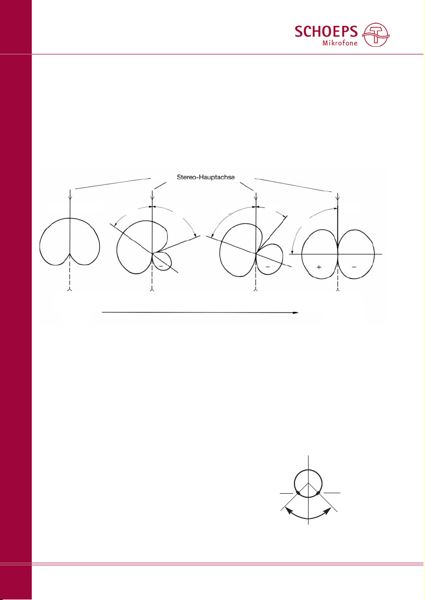
Abb. 10 MS mit Niere und Acht, dargestellt für den linken Kanal
ϕ
= Akzeptanzwinkel (Dieser ist hier größer als der Aufnahmewinkel.
Erst wenn er überschritten wird, treten Abbildungsfehler auf.)
ω
= Achsenwinkel (Winkel zwischen den Mikrofonen)
ω
=0°
ω/2
ω/2
ω/2
ϕ/2
ϕ/2
ϕ
=0°*
ϕ
=180°
Mono
S = 0%
M = 100%
unbrauchbar
S = 100%
M = 0%
Schallquelle, die immer weiter nach rechts
wandert, zunächst erwartungsgemäß immer
kleinere Pegel in dem nach links gerichteten
Richtdiagramm liefert. Dann aber, nach Überschreiten des Minimums im Polar diagramm,
wird das Signal wieder größer, und die eindeu-
tig rechts liegende Schallquelle wird auch im
linken Kanal wiedergegeben! Da das Signal
außerdem gegenphasig übertragen wird, sind
weitere Probleme erklärlich: Bei Dolby Surround
z.B. kommt es zu einer Abbildung der Schall quelle in den Surround-Kanälen.
Blumlein-Stereo
(rote Markierung; Abb. 4)
Mikrofone: die MK 8 oder die MK 6 in Stellung
“Acht”
Winkeln Sie die Klammern so an, dass sie
senkrecht von der Schiene weg weisen. Die
Mikrofone werden jeweils etwa bis zur Mitte
in die Klammern eingeführt. Sie sollten exakt
in einer Geraden ausgerichtet sein. Zwischen
den Kapseln sollte ein Abstand von ca. 3mm
verbleiben.
Nun sind nur noch die 0°-Achsen der Mikro fone auszurichten. Diese sind jeweils durch
einen roten Punkt gekennzeichnet. Ihre Orien tierung sollte so gewählt werden, dass die 0°-
Achsen (Abb. 12a,b) um 45° nach links bzw.
rechts weisen. Der Winkel ωzwischen ihnen
beträgt dann 90°.
90°
roter Punkt
linker Kanal
roter Punkt
rechter Kanal
Abb. 11a Orientierung der Mikrofone bei
Blumlein – von oben gesehen
Deutsch
zunehmendes Verhältnis von S/M
Page 9
SCHOEPS GmbH · Spitalstr. 20 · D-76227 Karlsruhe (Durlach) · Tel: +49 721 943 20-0 · Fax: +49 721 943 2050
www.schoeps.de · [email protected]
9
Deutsch
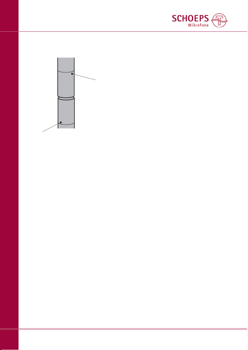
0°-Achse
0°-Achse
Abb. 11b Orientierung der Mikrofone bei
Blumlein – von vorne gesehen
Page 10
SCHOEPS GmbH · Spitalstr. 20 · D-76227 Karlsruhe (Durlach) · Tel: +49 721 943 20-0 · Fax: +49 721 943 2050
www.schoeps.de · [email protected]
Preface
10
English
The UMS 20 is a short microphone rail for
20 mm diameter microphones, in particular
for SCHOEPS microphones of the “Colette”
modular series. It is designed for setting up
the stereo recording configurations shown on
the left.
The UMS 20 should be used together with
the SG 20 stand clamp with swivel, or with the
A 20 S elastic suspension with swivel (both
separately available). This will allow you to tilt
it. The A 20 S also lets you clamp the microphone cables into holders to keep them slack.
The UMS 20 is mounted on the stand using
the supplied 20 mm cylinders (see Fig. 6 below),
which screw onto the threaded studs in the
middle of the rail or onto the end, depending
on the recording method.
The cylinder has a 5/8" 27 NS internal thread.
Fig. 1
X/Y, here at 90° with axially addressed microphones; yellow markings make it easier to adjust
the bracket positions
Fig. 3
M/S with microphones for axial pickup
(blue markings)
Fig. 2
ORTF, distance between capsules: 17 cm,
angle: 110° (green markings)
Fig. 4
Blumlein, X/Y, M/S with microphones for lateral pickup
(red markings)
Fig. 6
Fig. 5 A 20 S SG 20
A threaded adapter is supplied for 3/8" and
1/2" mounting.
The swiveling clamps snap into any of four
defined positions which are marked with
colored dots. Each color corresponds to a specific recording method.
UMS 20 Universal Stereo Bracket
Page 11
SCHOEPS GmbH · Spitalstr. 20 · D-76227 Karlsruhe (Durlach) · Tel: +49 721 943 20-0 · Fax: +49 721 943 2050
www.schoeps.de · [email protected]
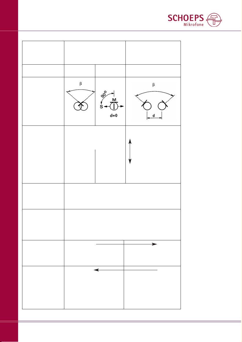
Survey – Recording Techniques possible with the UMS 20
11
English
*depends on the directional pattern and the
recording angle
(see Figs. 8, 9)
potentially very good*,
except that the center of
the stereo image can be
over-emphasized (not a
problem with figure 8s)
coincident microphone placement
5 cm – 30 cm
distance and angle
are interdependent
level differences +
minor arrival-time
differences
pressure-gradient transducer
(e.g. SCHOEPS cardioid MK 4 or CCM 4)
clean, clear, often bright
often rather limited satisfactory
good
Sonic impression
(depends on the
microphone used)
Acoustic operating principle of
the microphone
Distance (d)
between microphones
Angle between
microphones
X/Y M/S ORTF (for example)
70° – 180° 90° 0°–180°
0 cm
usually vertically aligned
Stereo recording principle
Name
Geometry
Spaciousness
Localization
Page 12
SCHOEPS GmbH · Spitalstr. 20 · D-76227 Karlsruhe (Durlach) · Tel: +49 721 943 20-0 · Fax: +49 721 943 2050
www.schoeps.de · [email protected]
X/Y Stereo
12
English
yellow = X/Y
green = ORTF
blue =M/S
red = Blumlein as well as X/Y and M/S
with laterally addressed microphones
Regardless of which recording method you
choose, you must always make the following
adjustments before attaching the microphones:
1. Loosen the lock screws on the undersides
of the carriages (see Fig. 7).
2. Turn and slide the carriages into place on
the microphone stand, matching up the
colored dots according to the chosen recording method. The carriages should snap into
place. Refer to the table above or to Figures
1–4 for the color coding.
3. Tighten the lock screws. (You can also lock
the carriages into an intermediate position
if necessary.)
4. Screw on the cylindrical fastener (see Fig. 6
below). Fasten it onto the end of the rail for
lateral pickup mics or Blumlein recording
(Fig. 4; red); otherwise fasten it onto the
middle.
rail
lock screw
marks
carriage
with clamp
Fig. 7
Carriage
Once you have made these adjustments, the
rest of the setup procedure depends on which
recording technique you are using:
X/Y Stereo
... with 90° and axially addressed microphones (yellow markings; Fig. 1):
Microphones: two MK 4 cardioids or MK 41
supercardioids.
Looking from the side of the rail with the
colored dots, angle the left clamp outwards
and the right clamp upwards. Insert the
microphones as shown in Fig. 1. Now you can
make the fine adjustments.
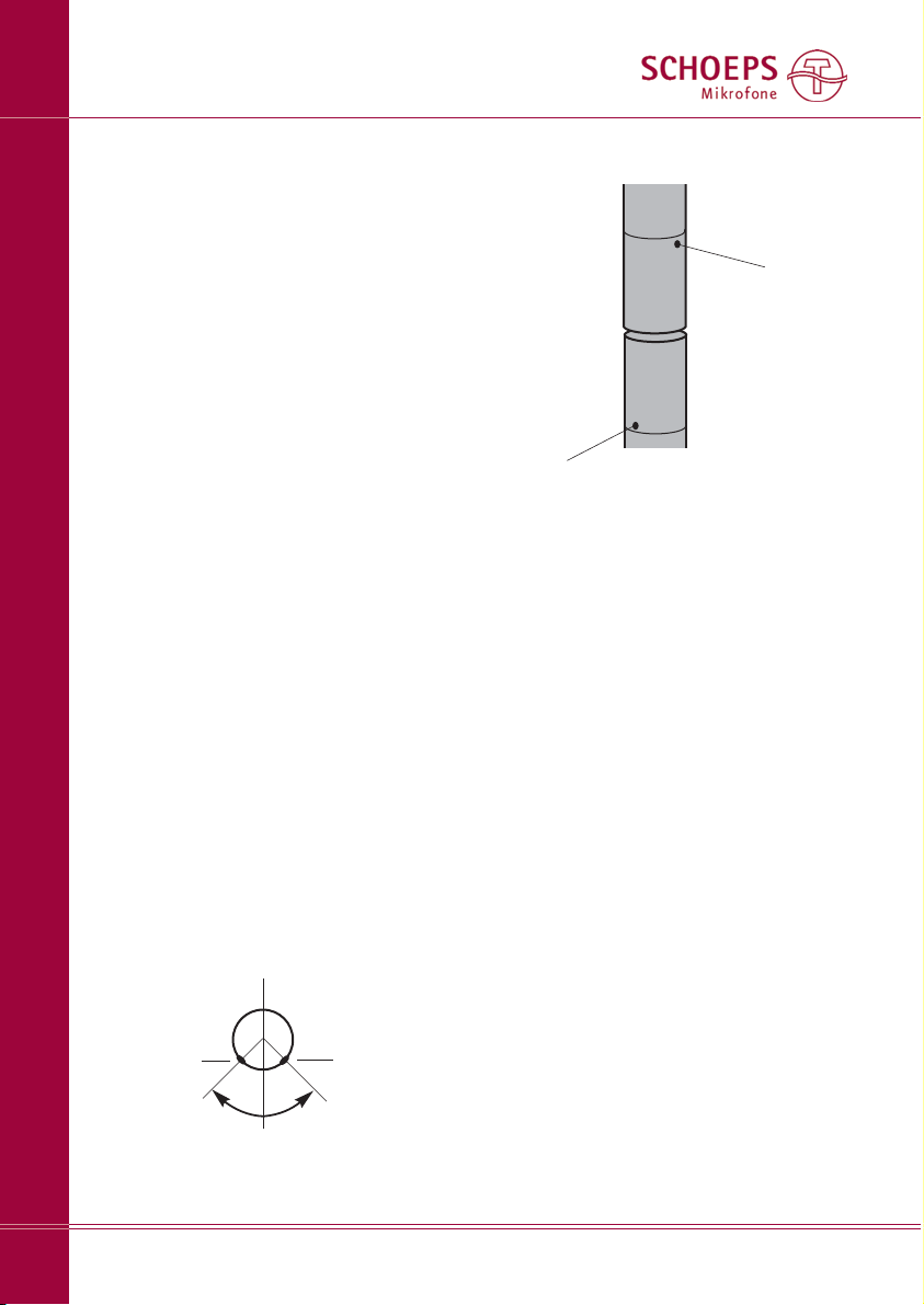
This is how the capsules should overlap,
looking from above:
The microphones should not be touching
each other – they should be about 3 mm apart.
Other axis and pickup angles can be set in
similar fashion. The pickup angle and corresponding values are explained in Figures 8
and 9.
X/Y with laterally addressed microphones
(red markings as for Blumlein; Fig. 4)
Microphones: MK 4V or MK 41V.
Angle the clamps so that they point vertically out from the rail. Insert the microphones
into the clamps, each to about halfway. They
should be aligned in a perfectly straight line.
There should still be a small gap between the
capsules (about 3 mm). The red dots on the
capsules indicate the pickup direction (0° axis).
You can set the axis angle, and with it the
pickup angle, by twisting the two microphones
(see Fig. 8 and 9).
left microphone =
right channel
right microphone =
left channel
Page 13
ORTF Stereo
(green markings; Fig. 2)
Microphones: two MK 4 cardioids.
Looking from the side of the rail with the
colored dots, angle the right clamp as far as it
will go and the left clamp 45° to the middle
of the rail (i.e. forwards). Insert the microphones into the clamps up to just below the
SCHOEPS logo. Now angle the left clamp until
the microphones are about 3 mm apart. The
middles of the capsules are now 17 cm apart.
The angle between the microphones is 110°.
Variations – Personal Settings
The UMS 20 can be used for a great deal
more than just ORTF and X/Y recordings. You
can make equally good recordings by choosing different angles and distances between
the microphones than the standard settings
described above. Here is a brief guide:
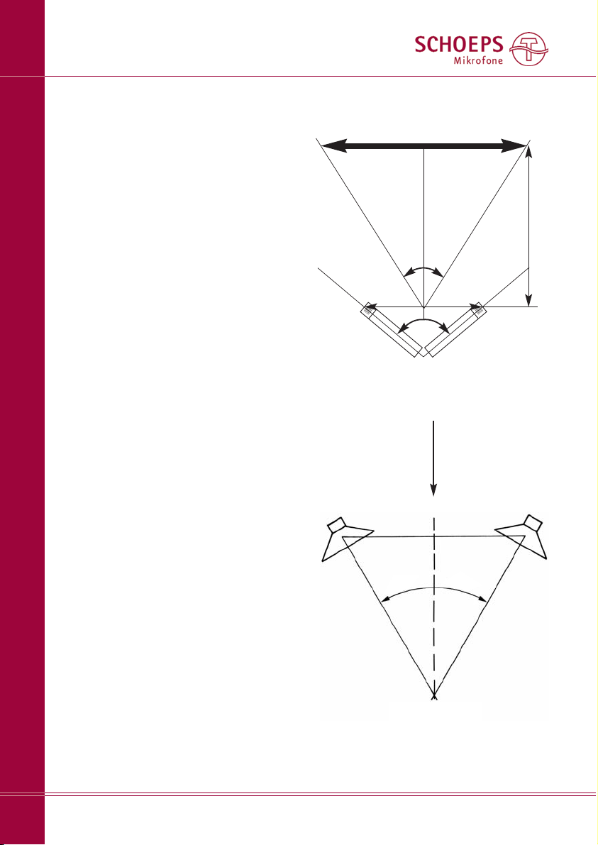
One of the essential aims when making
stereo recordings is to reproduce the pickup
angle α(s e e F ig. 8a) in an area of 60° during playbac k through loudspeakers (s ee
F ig. 8b) . T he crucial parameters for achieving this are:
1. the directivity of the microphones used,
2. their distance from the sound source,
3. the angle ωthat the microphone a xes
cover together, and
4. the distance d between the membranes of
the microphones.
How to Determine the Parameters
1. Since the UMS 20 holds the microphones
so close together, its use is practically limited
to techniques that use directional microphones
only, such as cardioids, supercardioids and
figure-8 (bidirectional) microphones.
2. The distance a of the microphone from the
sound source is especially important: The distance influences not only the stereo image,
but also the sound, since it defines the ratio
of direct to reflected sound (diffuse sound).
SCHOEPS GmbH · Spitalstr. 20 · D-76227 Karlsruhe (Durlach) · Tel: +49 721 943 20-0 · Fax: +49 721 943 2050
www.schoeps.de · [email protected]
ORTF Stereo
13
English
listener
Fig. 8b
The stereophonic recording angle
α
from
Fig. 4a is mapped into an angle α‘ of 60°
during loudspeaker playback..
α
’= 60°
d
α
ω
Fig. 8a
Stereophonic recording angle αand axis
angle ω; all direct sound sources should be
within the stereophonic recording angle.
main stereo
axis
Area to be recorded
(e.g. orchestra or band)
a
Page 14
SCHOEPS GmbH · Spitalstr. 20 · D-76227 Karlsruhe (Durlach) · Tel: +49 721 943 20-0 · Fax: +49 721 943 2050
www.schoeps.de · [email protected]
Variations with Cardioids
14
English
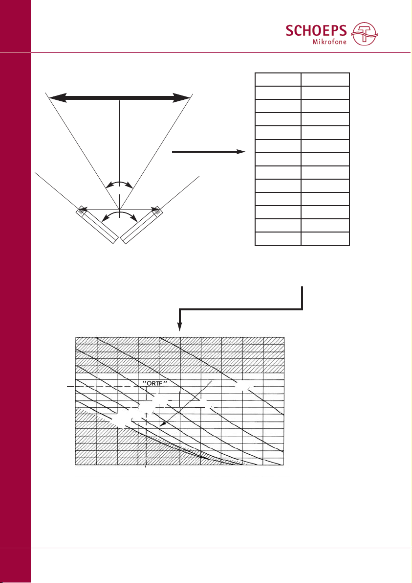
d
ω
Fig. 9a
Recording angle αand the angle ωbetween the
microphones; all sound sources should be lying
within the recording angle
α
main stereo
axis
Area to be recorded
(e.g. orchestra or band)
Table 1
This table can be used to determine
the stereophonic recording angle
α
from the ratio of b to a.
b/a angle
α
0.54 30°
0.73 40°
0.93 50°
1.15 60°
1.40 70°
1.68 80°
2.0 90°
2.38 100°
3.46 120°
5.50 140°
11,3 160°
oo 180°
a
b
Fig. 9b
ω
and distance d required between two cardioids as a function of the ratio b/a
(see Fig. 9a; simplified from Michael Williams)
spacing d of the microphones in cm
///// not usable
angle ωbetween
the microphones
0 5 10 15 20 25 30 35 40 45 50cm
180°
160°
140°
120°
100°
80°
60°
40°
20°
0°
60°
80°
100°
120°
140°
160°
180°
α
recording angle
α
b/a
α
Page 15
SCHOEPS GmbH · Spitalstr. 20 · D-76227 Karlsruhe (Durlach) · Tel: +49 721 943 20-0 · Fax: +49 721 943 2050
www.schoeps.de · [email protected]
M/S Stereo
15
English
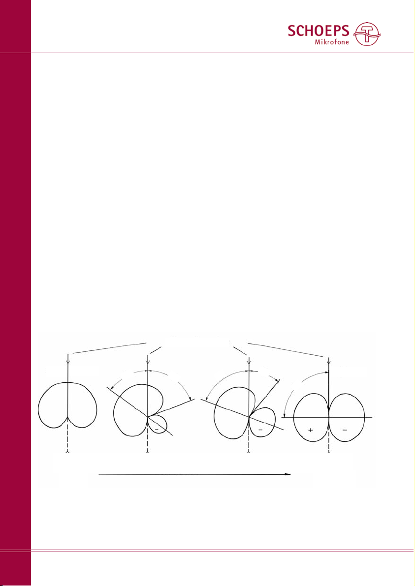
Fig. 10 M/S with cardioid and figure-8, shown for the left channel
ϕ
= acceptance angle; (this is greater than the pickup angle in this case.
Only when this is exceeded will reproduction errors arise.)
ω
= angle between the two “virtual microphones”
ω
= 0°
ω/2
ω/2
ω/2
ϕ/2
ϕ/2
ϕ
= 0°*
ϕ
= 180°
Mono
S = 0%
M = 100%
(unusable)
S = 100%
M = 0%
main stereo axis
increasing ratio of S signal to M signal
A short distance will sound ”dry” while
microphones placed at a large distance will
record ”more room.” The latter is usually
desired if the room has nice acoustics.
What this all implies is that it is best to
choose the distance primarily for aesthetic
purposes, where the acoustic properties of the
room are as important as anything else.
3. and 4.
In order to determine the angle ωand the
distance d between the microphones, you
first have to determine the pickup angle α.
You can do this with the help of Table 1 on
page 5. The pic kup angle αis ca lculated
from the ratio of the s ound s ource width b to
the distance a from the sound source (Fig. 9a).
In such a case, a and b have to be either estimated, paced out or measured.
You then look for the curve in Figure 9b
that comes closest to the pickup angle calculated in the manner just described. Along this
curve lie all possible settings for d and ωtha t
give the bes t reproduction of the stereophonic
recording angle within the playback area.
M/S Stereo
...with axially addressed microphones
(blue markings; Fig. 3)
Microphones:
For the mid signal: typically an MK 4 cardioid
or MK 41 supercardioid, or possibly an omnidirectional (MK 2S or MK 3);
for the side signal: an MK 8 capsule
(or MK 6 in figure-8 position).
Angle the clamps so that they point vertically out from the rail. Now insert the microphones. The clamps should grip the microphones as close as possible to the plug end.
Now, first angle one of the clamps down as
far as it goes towards the middle of the rail,
then angle the other clamp until it is touching
the first. Make sure the plug ends of the two
microphones are flush with each other. Then
the capsules will also be correctly positioned.
Now you need to align the pickup axis of the
side microphone (figure-8). This is correct
when the red dot on the microphone is facing
the left side of the sound source.
More information on MS with cardioids
and figure-8 is given in Fig. 10.
Page 16
SCHOEPS GmbH · Spitalstr. 20 · D-76227 Karlsruhe (Durlach) · Tel: +49 721 943 20-0 · Fax: +49 721 943 2050
www.schoeps.de · [email protected]
M/S / Blumlein Stereo
16
M/S with laterally addressed microphones
(red markings; Fig. 4)
Microphones:
For the mid signal: typically an MK 4V cardioid
or MK 41V supercardioid;
For the side signal: an MK 8 capsule (or MK 6
in figure-8 position).
Angle the clamps so that they point vertically
out from the rail. Insert the microphones into
the clamps, each to about halfway. They should
be aligned in a perfectly straight line. There
should still be a slight gap between the capsules (about 3 mm).
Now you only need to align the pickup axes
– indicated by a red dot on the capsules. These
are correctly oriented when the red dot of the
mid microphone is facing the sound source, and
the red dot on the side microphone is facing
left.
Blumlein Stereo
(red markings; Fig. 4)
Microphones: the MK 8 or MK 6 in figure-8
position
Angle the clamps so that they point vertically
out from the rail. Insert the microphones into
the clamps, each to about halfway. They should
be aligned in a perfectly straight line. There
should be a gap of about 3 mm between the
capsules.
Now you need only adjust the 0° axes of the
microphones. These are each indicated by a red
dot. Their orientation should be chosen such
that the respective 0° axes (Fig. 12a,b) face 45°
to the left and right. The angle ωbetween
them is then 90°.
90°
red dot of
the left
channel
red dot of
the right
channel
Fig. 11a Orientation of the microphones for
Blumlein recording – looking from above
English
0° axis
0° axis
Fig. 11b Orientation of the microphones for
Blumlein recording – looking from the front
Page 17

SCHOEPS GmbH · Spitalstr. 20 · D-76227 Karlsruhe (Durlach) · Tel: +49 721 943 20-0 · Fax: +49 721 943 2050
www.schoeps.de · [email protected]
17
English
Page 18

SCHOEPS GmbH · Spitalstr. 20 · D-76227 Karlsruhe (Durlach) · Tel: +49 721 943 20-0 · Fax: +49 721 495 750
www.schoeps.de · [email protected]
18
English
Page 19

SCHOEPS GmbH · Spitalstr. 20 · D-76227 Karlsruhe (Durlach) · Tel: +49 721 943 20-0 · Fax: +49 721 495 750
www.schoeps.de · [email protected]
19
English
Page 20

Änderungen und Irrtümer vorbehalten.
Subject to change without notice.
Not responsible for errors or omissions.
100301
Technik
Schall
SCHOEPS GmbH
Spitalstr. 20
D-76227 Karlsruhe (Durlach)
Tel: +49 721 943 20-0
Fax: +49 721 943 2050
www.schoeps.de
[email protected]
 Loading...