

Schoeps UNIVERSAL-OMNI-H-ST, UNIVERSAL-OMNI-S-ST, WIDE-CARDIOID-ST, SWITCHABLE-PATTRN-ST, SUPERCARDIOID-ST Users Manual
...Page 1
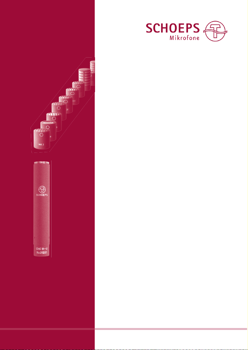
MK --
Microphone Capsules
CMC --
Microphone Amplifiers
User Guide
Colette
Modular System
Colette
Modular System
Table of Contents
page
System Overview 2
CMC -- Microphone Amplifiers 3
Phantom Powering 5
Technical Specifications 7
Notes on Electromagnetic Compatibility 7
Block Diagram 8
MK -- Microphone Capsules 9
Capsule Selection 9
Attaching a Capsule 9
Basic Characteristics of Transducers 10
Suggested Capsules for Specific Applications 11
Pressure Transducers 12
Boundary Layer Microphones 13
Pressure Gradient Transducers 14
Specifications for Complete Microphones 21
Care and Maintenance 22
Possible Problems 22
Warranty 24
Page 2
SCHOEPS GmbH · Spitalstr. 20 · D-76227 Karlsruhe (Durlach) · Tel: +49 721 943 20-0 · Fax: +49 721 943 2050
www.schoeps.de · [email protected]
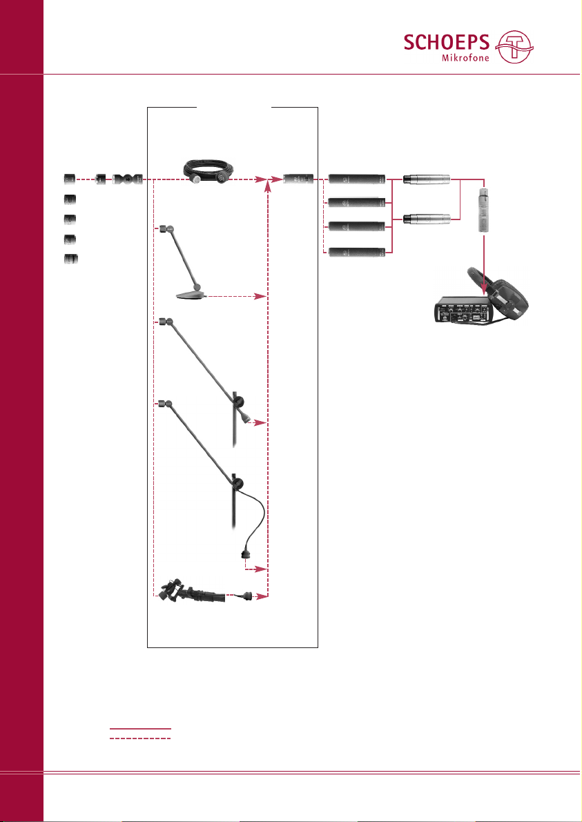
System Overview (Extract)
Colette Modular System
2
inline filters
inline
attenuator
microphone
capsules
attenuator
swivel
low-cut
filter
microphone
amplifiers
.
.
.
20 capsules
in all
RC KC
Active Tube
(special
version)
MK DZC GVC
KC
Active Cable
CUT
Signal:
balanced
unbalanced
TR 200 KCg Active
Table Stand
RC
Active Tube
LP 40 U
low-pass filter
Active Accessories
CMC 6, P12 / P48
CMC 3, P12
CMC 5, P48
LC 60, LC 120
low-cut filters
OSIX CI
elastic suspension
with Active Cable
e.g. VMS 5 U
microphone preamplifier
with M/S matrix
MDZ 10,
MDZ 20
CMC 4, T12
Page 3
SCHOEPS GmbH · Spitalstr. 20 · D-76227 Karlsruhe (Durlach) · Tel: +49 721 943 20-0 · Fax: +49 721 943 2050
www.schoeps.de · [email protected]
CMC -- Microphone Amplifiers
Microphone Amplifiers
3
Dear customer:
Thank you for choosing SCHOEPS CMC
(”Colette”) Series microphones. This is the most
extensive and diverse modular microphone
system in the world, offering the highest possible professional sound quality in an extremely
wide range of practical configurations. A system
overview is shown on page 2.
Colette Modular System
A condenser microphone is formed by the
combination of two main components: a capsule and a microphone amplifier:
The capsule is the component which converts
sound waves into a varying electrical voltage.
It determines the directionality and, for the
most part, the sound quality of the microphone.
The amplifier is the other main component,
with the circuitry needed to accept external
powering, polarize (charge) the capacitive
capsule, obtain the audio signal from it, and
convert that signal to one which is balanced
and low-impedance.
Microphones of the Colette Series are modular: Any type of CMC microphone amplifier
can be used with any type of Colette capsule.
Approximately 20 different capsule types (MK --)
are available for wide-ranging applications,
and several types of amplifier (CMC --) are
available for various powering and connection
schemes.
In addition, the practical value of a Colette
Series microphone is greatly enhanced by
Colette ”Active Accessories” – special goosenecks, ultra-thin cables or narrow extension
tubes which allow the capsule to be separated
some distance from its amplifier and placed
unobtrusively, as if it were a miniature microphone. Colette Active Cables are often used
to help conceal microphones for film and video
production, while Colette Active Extension
Tubes have become a mainstay of concert
amplification, recording and broadcasting.
The active circuitry in these accessories converts
the audio signal to lower impedance directly
at the capsule, so that there is no loss of sound
quality:
In the following pages you will find technical
information, application hints and advice concerning the care and maintenance of these
microphones. We begin by considering the
CMC amplifier and how to power and connect
SCHOEPS condenser microphones; the second
part of this manual concerns the capsules of
the Colette Series. For information on accessories (including Active Accessories), please see
our main catalog or visit www.schoeps.de.
CMC -- Microphone Amplifiers
...are distinguished by:
– flat frequency response
– low noise and distortion
– balanced, symmetrical, very low-impedance
output
– ability to be used with very long cables
(e.g. several hundred meters)
– versions for various powering schemes
Several standard versions are available. All
feature a symmetrical, class-A output stage
which uses neither coupling conden sers nor an
output transformer. This leads to a low output
impedance, insensitivity to electrical interference, low distortion and light weight.
CMC amplifiers are electrically active com po nents which require operating current. This
will most often be supplied by the inputs of a
mixer, preamplifier (such as the SCHOEPS
VMS 5U shown on page 2) or recorder that
has suitable microphone powering built in.
Otherwise, a stand-alone microphone power
supply of proper type can be used.
Standard Versions
Four standard models of CMC amplifier are
offered to fit the specific type(s) of microphone
MK-- CMC--
+
++
Active Accessories
Page 4

powering which the user expects to encounter.
Variants of these types are also available, offering different output levels and/or extended
frequency range. Each amplifier works only with
the specific type and voltage(s) of power ing
for which it is designed.
Please note: The two amplifiers in a stereo pair
of CMC microphones should be of the same
type. For critical applications, pairs of capsules
can be selected at the factory for pre cisely
matched sensitivity and frequency response.
(A small extra fee is charged for this service.)
Most modern, solid-state professional micro phones use a standardized powering scheme
known as ”phantom powering,” and most
recording equipment offers a 48-Volt supply
for such microphones. Some equipment, however, provides a 12-Volt supply for phantom
powering, or can be readily modified to provide
such a supply. The SCHOEPS CMC 6 amplifier
series can work with either voltage, switching
its circuitry automatically to the corresponding
mode of operation. It maintains the same level
of performance in either mode, while drawing
only the necessary amount of current from the
phantom supply.
Note that the CMC 6 is designed to work
with standard 12-Volt or standard 48-Volt
phantom powering, but it is not a ”12-to-48
Volt” microphone. Any input to which it is
connected must implement one of those two
standard phantom powering methods. Not
only must the supply voltage meet the standard; the resistors must be correct as well.
For applications in which it is certain that only
48-Volt or only 12-Volt phantom powering
will be used, the CMC 5 and CMC 3 (respec tively) remain available at slightly lower cost.
The CMC 6 offers greater flexibility in powering
as well as superior immunity to radio-frequency
interference; it is also the only amplifier model
which can be delivered in the special ”xt” version (see description under ”Special Versions”
below).
From an audio standpoint, the most significant difference between the CMC 6 and the
CMC 3 or 5 is the response at the very lowest
audio frequencies: The standard version of the
CMC 6 has a 12 dB/octave rolloff below 20 Hz
as a protection against infrasonics, while the
stan dard version of the CMC 3 or 5 has a 6 dB/
octave rolloff below 30 Hz. Any CMC amplifier
can be specially ordered, or modified after
delivery, for any desired rolloff frequency within
reason; please see the description of the CMC
”linear” version for further details.
In general if a 48-Volt microphone is connected to 12-Volt phantom powering, no damage will occur but the microphone will not work
properly. On the other hand a CMC 3 could
be powered safely and effectively by a 48-Volt
phantom supply if it can provide 11 mA per
microphone. But that current exceeds what is
required for standard 48-Volt phantom powering, and unfortunately many existing supplies
do not even meet the standard. Therefore this
mode of operation should not normally be
relied upon.
In the realm of film and video sound an
older system called ”parallel powering” or ”T”
powering (”Ton ader spei sung”) at 12 ± 1 Volts
is sometimes still used, particularly with Nagra
tape recorders; the CMC 4 amplifier model
works with that system. See Fig. 3, p. 6 for a
schematic diagram; since this method of powering has been in decline for some time now,
it is not described in detail in this manual.
Please contact your SCHOEPS dealer or SCHOEPS
GmbH with any questions concerning its use.
Special Versions
CMC 6 U”xt” – the 40 kHz version
This variant is indicated by the letters ”xt”
engraved on the output socket. When an ”xt”
amplifier is used with any axially-addressed
Colette capsule, the response range of the
microphone will extend beyond 40 kHz. The
response above 10 kHz will also be elevated
slightly. Specific frequency response curves
can be seen in our main catalog or on our
Web site, www.schoeps.de .
CMC “+5 dB”
The sensitivity of a microphone with this ampli fier variant is 5 dB above the normal type,
while the equivalent noise level is somewhat
GmbH · Spitalstr. 20 · D-76227 Karlsruhe (Durlach) · Tel: +49 721 943 20-0 · Fax: +49 721 943 2050
www.schoeps.de · [email protected]
Types of Microphone Amplifiers
Microphone Amplifiers
4
Page 5

greater. The increased output levels can help
to raise a microphone's signal above the input
noise level of the equipment to which it is
connected, especially when sound levels are
low to moderate. However, the overload limit
of that equipment, and of the microphone
itself, will also be reached 5 dB sooner.
CMC ”linear”
CMC microphone amplifiers normally have a
rolloff in response below 30 Hz (20 Hz in the
CMC 6) to guard against infrasonic disturbances from various sources such as vibration
and air motion. However, when using pressure
(omnidirectional) transducers, particularly with
digital recording, it can be desirable to pick up
frequencies even lower than 20 - 30 Hz. The
special technology of the CMC microphone
amplifiers makes this possible; on request we
can deliver microphone amplifiers with response
extending as low as 3 Hz.
For live recording, however, some caution
is advised with respect to infrasonics. Since
pressure transducers can pick up very low frequencies, ventilation systems in large spaces
(churches, concert halls) or traffic rumble can
create a problem. With pressure gradient trans ducers the risk is even greater. They are far
less sensitive to very low frequency sound, but
respond much more strongly to low-frequency
mechanical stimuli such as air currents and
solid-borne noise. Such signals may be below
the audible range, but they can overload preamp inputs, particularly those that have
undersized input transformers.
Phantom Powering (DIN EN 61938)
(formerly DIN 45 596)
”Phantom” powering is a standard method of
providing the operating current for a microphone's circuitry through ordinary two-conductor shielded cable. Precisely equal DC flows in
both modulation leads, making it ”invisible”
and harmless to most balanced microphones
that don't require such powering (e.g. most
dynamic microphones, including ribbons).
Exceptions are quite rare. The only likely cases
in which standard phantom powering will en -
danger a balanced microphone (e.g. a ribbon)
are if a microphone cable, con nector or adapter
is defective or wired in a non-standard way,
such that one modulation lead of the microphone is shorted to ground at DC while the
powering is on. If a microphone is connected
to such a cable with the powering turned on,
impulse current will flow through its coil or
ribbon, possibly causing damage.
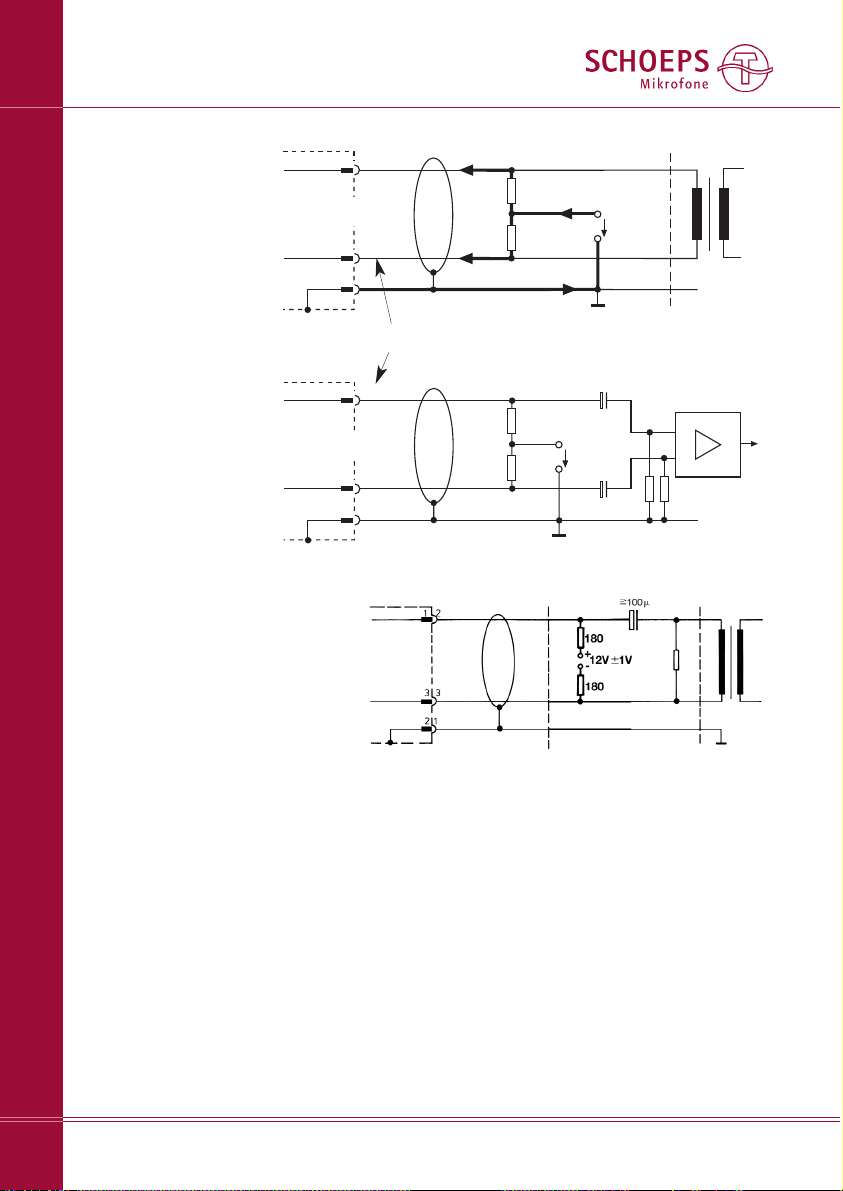
Fig. 1 shows the only valid 48 V and 12 V
phan tom powering circuit (abbreviations: P48
and P12) that can be realized with resistors as
opposed to a center-tapped input transformer.
This illustration is based on the international
standard document EN 61938, ratified in
1997. Our microphones are developed and
tested with power supplies that con form to
the requirements of this standard. Proper operation with non-standard power supplies cannot be guaranteed. Circuit arrangements that
deviate from the standard can cause operational problems (i.e. distortion or even gaps in
the signal), particularly at high sound pressure
levels or in the presence of strong wind noise.
Such problems may often seem to defy analysis
until their real cause is discovered.
The permissible tolerance of the feed resistor
values as such is ±20%. However, the difference between the resistors of any one pair
should be less than 0.4% (i.e. 27 Ohms for
48-Volt phantom powering with 6.8 kOhm).
This close matching is necessary to maintain
adequate common mode rejection. It will also
prevent significant DC from flowing through
the primary of the input transformer (if one is
present) and causing distortion or reduced
dynamic range.
A microphone designed for 48-Volt phantom powering could draw as much as 10 mA
according to the standard. A SCHOEPS CMC 5
or CMC 6 will draw about 4 mA even when
Active Accessories are used; this falls well
within the limit set by the prevailing standard.
There are certain commercially available power
supplies, preamplifiers, and mixing desks –
mostly older, but some more recent – which
fail to meet this standard and hence may not
be able to power SCHOEPS microphones adequately. Where doubt exists, equipment should
SCHOEPS GmbH · Spitalstr. 20 · D-76227 Karlsruhe (Durlach) · Tel: +49 721 943 20-0 · Fax: +49 721 943 2050
www.schoeps.de · [email protected]
Phantom Powering
Microphone Amplifiers
5
Page 6
SCHOEPS GmbH · Spitalstr. 20 · D-76227 Karlsruhe (Durlach) · Tel: +49 721 943 20-0 · Fax: +49 721 943 2050
www.schoeps.de · [email protected]
Phantom Powering
Microphone Amplifiers
6
If possible, an unbalanced input should be balanced with a high-quality microphone input
transformer. That will also allow the signal leads
from the microphone to be balanced, for best
rejection of interference.
If such an arrangement is not possible, however, a CMC microphone may be operated in
unbalanced mode by taking the signal from
pin 2 via a coupling condenser with a value as
shown in Figure 2 above. The signal from pin 3
must be left unconnected; do not short it to
ground. This ”unbalancing act” must occur
between the power supply and the preamplifier
input, however, since naturally all three pins
of the microphone must still connect to its
phantom or parallel power supply.
+ phase
- phase
2 (4)
3 (5)
microphone
1
screen
cable
powering
R
S
U
S
input
R
S
P48: US= 48 V ± 4 V; RS= 6,8 kW*, I
max.
= 10 mA
P12: U
S
= 12V ± 1V; RS= 680 W*, I
max.
= 15 mA
I/2
I/2
I
+ phase
- phase
2 (4)
3 (5)
microphone
1
screen
cable
powering
R
S
U
S
input
R
S
R
R
C
C
* see note in the text concerning tolerances
with XLR-5
(stereo microphones)
Fig. 2
To add phantom powering
to a balanced, grounded,
transformerless input, capa citors must be inserted into
the signal lines and polarization resistors provided as
shown.
*
*
*
Fig. 1
Input with transformer
(or balanced, floating transformerless input)
XLR-3connector
XLR-3
connector
XLR-3connector
cable
Ohms
Ohms
* recommended values:
C: 100
μ
F, 63V; R: 22kΩ, 1%
** Tolerance ca. 5%; precise
matching is not critical.
Fig. 3
Parallel powering;
with parallel powering there is low-impedance
DC across pins 2 and 3. This can damage
dynamic microphones, especially ribbons.
z.B.
10 kOhm
**
**
R
*
be checked to verify its suitability for professional work with SCHOEPS microphones. On
page 8 a method is described for checking a
phantom supply quickly and easily.
For P12 the standard allows a current of
15 mA. A SCHOEPS CMC 3 will draw 11 mA
while a CMC 6 needs 8 mA at 12 Volts.
Fig. 2 shows a bal an ced but groun ded am pli fier in put. In this case eit her a trans for mer
(see fig. 1) or ad di tio nal ca pa ci tors ha ve to be
in ser ted in the au dio li ne.
Unbalanced Operation
Unbalanced operation of CMC microphone
amplifiers is not recommended; both noise and
vulnerability to interference will be increased.
shield
shield
shield
Page 7

SCHOEPS GmbH · Spitalstr. 20 · D-76227 Karlsruhe (Durlach) · Tel: +49 721 943 20-0 · Fax: +49 721 943 2050
www.schoeps.de · [email protected]
Technical Specifications, Electromagnetic Compatibility
Microphone Amplifiers
Amplifier type Powering Current Impedance Low-cut
consumption frequency (-3 dB)
CMC 6U / 6Uxt: 12 V phantom 8 mA 25 Ohms 20 Hz
48 V phantom 4 mA 35 Ohms 20 Hz
(automatic switchover)
CMC 5U: 48 V phantom 4 mA 35 Ohms 30 Hz
CMC 3U: 12 V phantom 11 mA 20 Ohms 30 Hz
CMC 4U: 12 V parallel 9 mA 13 Ohms 30 Hz
Polarity: Increasing sound pressure on the microphone's 0° axis produces a positive-going voltage
at pin 2.
Maximum output voltage: 1 V (at 1 kHz and 1 kOhm load resistance)
Minimum recommended load resistance: 600 Ohms (A load resistance below this value will par-
ticularly reduce the maximum output level.)
The other technical specifications depend on the choice of capsule – see page 12 ff.
Length: 116 mm (incl. 3 mm capsule thread)
Diameter: 20 mm
Weight: 65 – 68 g, depending on type
Surface finish: matte gray (g) or nickel (ni)
electromagnetic fields. This is particularly true
for CMC 6 amplifiers made since 2004; they
can be recognized by the gold-colored shield
plate in their output connector.
Due to the wide dynamic range of studio
microphones, the smallest signal amplitudes
are in the microvolt (1/1,000,000 Volt) range.
Cable shielding and the grounding scheme of
the preamp or mixer input are also crucial.
Thus no microphone can ever be immune to
all possible disturbances under all circumstances.
But the following suggestions can help to
reduce the likelihood of picking up noise:
1) Keep both the microphone and the cable
away from sources of interference such as
monitors, digital equipment (computers),
RF emitters (mobile phones), power trans-
formers, power lines, SCR dimmers, switch-
ing power supplies etc.
2) Use only high-quality cables with a high
degree of shield coverage.
3) Keep all cables as short as possible.
4) Dress audio cables away from power cables.
If they must cross, it should be at right angles.
5) At the preamp or mixer input, the shield of
the microphone cable should connect to
chassis ground in the shortest way possible.
If necessary, this coupling can be capacitive.
Simultaneous Connection to Multiple Inputs
If one microphone must be connected to multiple inputs simultaneously, an active micro phone
splitter should be used in order to preserve
the loading and powering conditions for the
microphone, and to prevent interference.
Maximum Cable Length
Cable lengths of several hundred meters are
possible; Colette Series microphones are some times used with cables as long as 500 m (over
1/4 mile!). But the practical limit depends on
the electrical capacitance of the cable, which
is sometimes an unknown quantity. The lower
this capacitance is per unit length, the longer
the cable can be. All SCHOEPS cables have
very low capacitance (100 pF/m between the
conductors).
The main risks with excessively long microphone cables are losses at high frequencies
due to cable capacitance, reduced ability to
handle very high sound pressure levels, and
increased likelihood of picking up interference.
No tes on Electromagnetic Compatibility
SCHOEPS CMC microphone amplifiers are
virtually immune to magnetic, electric and
7
Page 8
SCHOEPS GmbH · Spitalstr. 20 · D-76227 Karlsruhe (Durlach) · Tel: +49 721 943 20-0 · Fax: +49 721 943 2050
www.schoeps.de · [email protected]
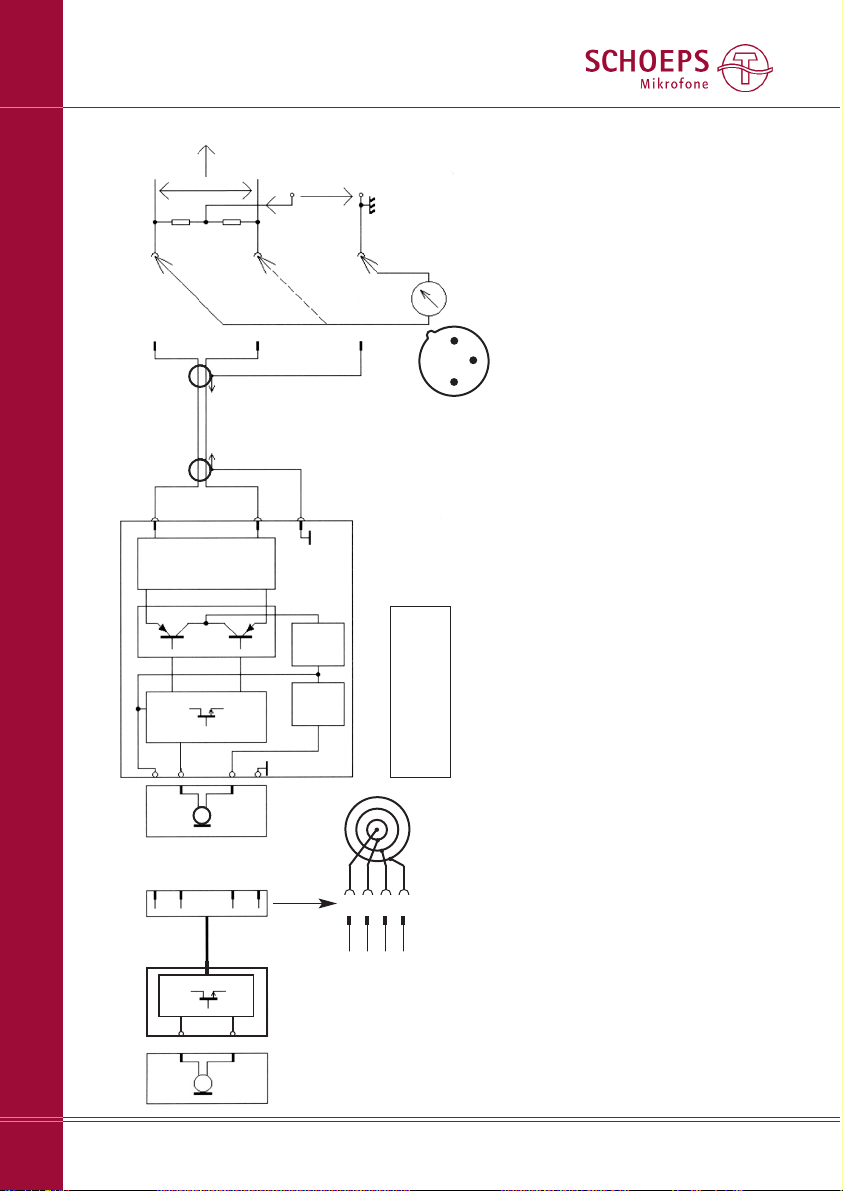
Block Diagram of the CMC 3, 5, 6 Microphone Amplifiers
Microphone Amplifiers
8
Capsule
MK --
Capsule
MK --
Impedance
converter
Output
stage
DC/DC
converter
Regulator
EMI filter
e.g. cable KC -- or
tube RC --
Active Accessories:
3
1
4
2
3
1
3
1
3
1
4
2
3
1
Screen
-Phase
+Phase
XLR-3
Connector
2
3
1
2
3
1
2
Center contact ( )
Inner ring (0 V)
Middle ring (+60 V)
Outer ring (+6,2 V)
Microphone
cable
Microphone Amplifier
CMC --
Phantom
powering
U
s
= +48 V
R
s
= 6.8 kΩ
R
s
= 6.8 kΩ
∼
∼
Preampli -
fier,
recorder
or mixing
desk
4
1
2
3
*
*
**
∼
∼
3
1
Impedance
converter
+Phase: An excursion of the diaphragm towards the back electrode (posi-
tive pressure phase) leads to a positive signal at this pin.
*matched pair; see page 5
** Here are three simple methods for verifying correct phantom powering.
These measurements should be made at an unused input. Reduce the
channel gain to protect loudspeakers, etc. If microphones are connected
to other inputs at the same time, no substantial difference should occur
in the results.
1. Measure the open-circuit voltage between ground (pin 1) and either
pin 2 or pin 3 of the XLR input. Given the permitted tolerances, this
voltage should be between 44 and 52 VDC for P48, and between 11
and 13 VDC for P12. Then, measure the short-circuit current between
ground (pin 1) and either pin 2 or pin 3 of the XLR input. Given the per-
mitted tolerances, this current should be between 5.9 and 8.5 mA DC
for P48, and between 15 and 21 mA DC for P12.
screen
-phase
+phase
XLR-3
connector
XLR-3
connector
Pin 1: screen (GND)
Pin 2: +phase
Pin 3: –phase
Bottom view
(as the pins are seen)
1
2
3
Note: Well-designed phantom power supplies must tolerate at least a
temporary short circuit without damage; an unbalanced connection
(which is occasionally necessary) would cause the same current to be
drawn. To be safe, however, don't leave the short circuit in place longer
than necessary.
2) Measure the DC voltages on the modulation leads with a microphone
connected, e.g. by opening the connector shell of the cable. The two
voltages (from pin 2 and pin 3 to pin 1) must be identical. With a CMC 5
or CMC 6 and a 48-Volt supply, they should be about 34 Volts (mini-
mum = 30 Volts). For P12 this is 8.3 Volts (minimum 7.3 Volts) with a
CMC 3, and 9 Volts (minimum 8 Volts) with a CMC 6.
3) For P48, use a SCHOEPS PHS 48 tester. Plug it in to the XLR input socket;
if the LED glows and stays lit, all is well.
Nominal voltage gain: stan-
dard CMC amplifier: -2 dB,
”+5 dB” version: +3 dB.
Page 9
MK -- Microphone Capsules
Which is the Best Capsule for ... ?
Only in rare cases can ”the” correct microphone be chosen unequivocally. The recording
location, the positions of sound sources and
the microphone, the atmosphere of the music
or other program material and the desired
effect must all be considered. Any absolute
prescriptions would thus be of limited value at
best. How ever, we would like to offer some
ideas to guide the choice that must be made.
Our Recommendations
The most commonly used pattern for mediumdistance pickup is the cardioid (MK 4 or MK 4V).
However, there may be good reasons to make
a different choice. Some examples:
– Greater directivity may be required, either for
the sake of a ”drier” recording or to sup-
press sound from adjacent instruments. In
this case we recommend the supercardioid
MK 41 (as long as no nearby sound source
or P.A. loudspeaker is directly behind the
microphone's rear lobe).
– For a broader pickup pattern, with very nat-
ural sound quality for sound arriving at the
sides of the microphone and more extended
low-frequency response, we recommend
the MK 21 wide cardioid.
– For essentially perfect pickup of low-fre-
quency information and room sound, we
recommend the omnidirectional MK 2H or
MK 2S (for moderate miking distances).
– When using directional microphones with
very close placement, proximity effect must
be compensated with a bass rolloff. This is
especially true when miking instruments.
For voice, try the MK 4S or MK 4VXS. For
instruments the omnidirectional MK 2 may
be of interest (no proximity effect, low sen-
sitivity to ”popping” or solid-borne noise);
for grand piano, the BLM 03 C.
– For very distant miking and/or as an ”ambi-
ence” microphone, with essentially perfect
bass response: omni MK 3.
– For outdoor recording if directivity is not
required (e.g. close miking), the omni MK 2S
with windscreen W 5 or W 5 D will offer low
sensitivity to wind, ”popping” and handling
noise.
If high directivity is required outdoors, the
MK 41 can be used with the W 5 D, W 20 R1
or WSR MS ”basket”-type windscreens with
built-in elastic suspension for mono or stereo.
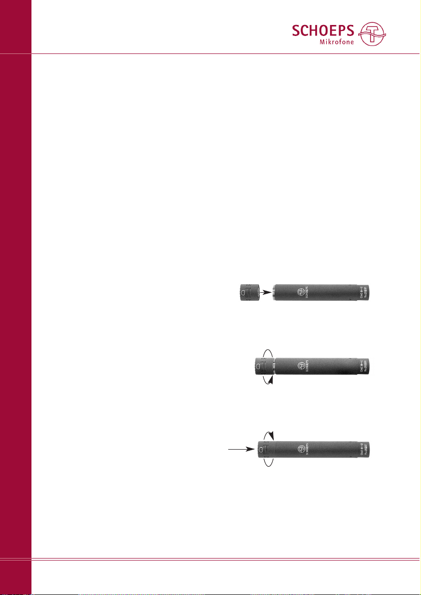
Attaching a Capsule or An Active
Accessory
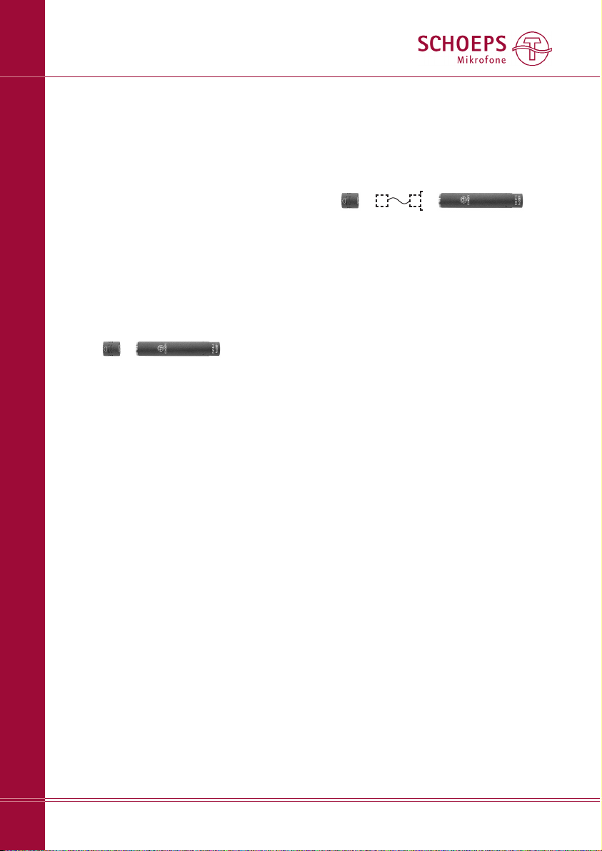
MK -- capsules are interchangeable and can
be screwed onto any CMC -- amplifier or
Active Accessory (see System Overview, page 2).
To avoid damaging the threads, please proceed
as follows:
Place the capsule against the front end of
the microphone amplifier.
Now turn the capsule first counter-clockwise
(not pressing the parts together) until you feel
a gentle ”click”:
You are then at the beginning of the thread,
and can attach the capsule or accessory to the
microphone amplifier with normal clockwise
rotation:
(The engraved markings on the capsule may
not always line up as shown with those on the
amplifier.)
If you are using an Active Accessory, attach it
to the microphone amplifier in a similar man ner.
SCHOEPS GmbH · Spitalstr. 20 · D-76227 Karlsruhe (Durlach) · Tel: +49 721 943 20-0 · Fax: +49 721 943 2050
www.schoeps.de · [email protected]
Capsule Selection
Capsules
9
Page 10

SCHOEPS GmbH · Spitalstr. 20 · D-76227 Karlsruhe (Durlach) · Tel: +49 721 943 20-0 · Fax: +49 721 943 2050
www.schoeps.de · [email protected]
Basic Characteristics of Transducers
Capsules
10
Essentially flat, with perfect reproduction of low frequencies. The on-axis
response of the free-field capsule does
not have a high-frequency emphasis
but the capsule meant for the reverberant sound field does.
Omnidirectional pattern in its ideal
form at low and middle frequencies.
At very high frequencies there is
increasing directivity. For this reason
even omnidirectional microphones are
aimed toward the sound source.
No proximity effect
Very little; simple foam-type windscreens are usually sufficient.
Reduced sensitivity (rolloff) at lower
frequencies, which can be compensated by close placement to the
sound source (proximity effect)
Types: wide cardioid, Open Cardioid,
cardioid, supercardioid (hypercardioid), bidirectional (figure-8). The
frequency response of our figure-8 is
nearly the same in all directions; the
wide cardioid capsule has this advantage also.
Proximity effect: Elevation of the low
and low-mid frequencies as working
distance decreases (quite noticeable
at less than 50 cm)
Possibly considerable; shock mounts
and more elaborate windscreens
may be necessary.
Characteristics of the Two Basic Transducer Types
All the wide variety of SCHOEPS capsules, without exception, are single-diaphragm electrostatic transducers. They fall into two general categories: pressure transducers and pressure gradient transducers.
Many of our capsules combine the two principles of operation in various proportions, yielding patterns from wide cardioid through supercardioid; these capsules are classed as pressure gradient
transducers by convention.
Unlike dual-membrane capsules, our switchable capsule offers flat low-frequency response, low
sensitivity to wind and solid-borne noise, and no proximity effect in its omnidirectional setting. In its
cardioid setting it maintains its directional pattern to the lowest frequencies, which dual-diaphragm
capsules do not do.
The following table lists the basic characteristics of these two general types.
SCHOEPS ”Colette” Series capsules (MK --) can be used interchangeably on all CMC-series amplifiers.
They can also be used with three special-purpose amplifier types: the CMBI (powered by internal battery, with unbalanced output), the VST 62 IU (two-channel, balanced, phantom-powered) and the M 222
(modern, transformerless vacuum-tube circuitry). The operating requirements and range of accessories
for these amplifiers vary; for detailed information please see the main catalog or www.schoeps.de.
Pressure Transducers (omnis)
MK 2, 2H, 2S, 3,
BLM 3, BLM 03C
MK 5 in the ”omni” position
Pressure Gradient Transducers
MK 21, 21H, 22, 4, 4V, 41, 41V, 8
MK 5 in the ”cardioid” position,
MK 4S, 40, 4A, 4VXS, 41S
Frequency
response:
Directional
pattern:
Near field
behavior:
Sensitivity to
vibration, wind
and popping:
Page 11

SCHOEPS GmbH · Spitalstr. 20 · D-76227 Karlsruhe (Durlach) · Tel: +49 721 943 20-0 · Fax: +49 721 943 2050
www.schoeps.de · [email protected]
Suggested Capsules for Specific Applications
Capsules
11
Applications: Recommendations:
On a lectern MK 4 (cardioid) with close-speech guard B 5 D
Conference recording MK 4 (cardioid) with close-speech guard B 5 D
TV speaker’s table MK 4 (cardioid), no popscreen required at distances greater than
0.5 m
Radio announcer MK 4V (cardioid with lateral pickup) with pop filter PR 120 SV
Noisy environments (super-)cardioid for close pickup (10 – 20 cm) with bass rolloff:
MK 4S, MK 40, MK 41S
TV “round table” discussion MK 4 (cardioid) or boundary layer capsule BLM 03 Cg (hemisphere)
Church MK 40 (cardioid) (perhaps as boundary layer microphone with BLC),
or BLM 03 C
Stage radio microphone type HXiR (AUDIO Ltd.) with MK 4 (cardioid) and
B 5 D popscreen or MK 2S (omni)
News reporting MK 5 (omni / cardioid, switchable) with windscreen B 5 D or W 5 D
or W 20 R1 (use the omni setting if there is strong wind)
Stage (movable) radio microphone HXiR (AUDIO Ltd.) with MK 4 (cardioid) or MK 2S
(omni) and popscreen B 5 D
Stage (fixed) MK 4 (cardioid) on RC Active Tube with windscreen B 5 D, vocalist
microphone CMH 64 (cardioid)
Studio MK 4, MK 4V (cardioids), MK 22 (Open Cardioid) with pop filter
PR 120 S, PR 120 SV
All instr. incl. percussion: MK 4 (cardioid); to pick up room sound as well:
especially for organ: MK 2S (omni); especially when the room’s character is less than opti-
mal or if the bass is too strong: MK 21 (wide cardioid) or MK 4
(cardioid)
Tympani, bass drum, etc. pressure transducers, e.g. MK 2
Instruments with adapters flute: MK 8 (figure-8), violin: MK 4V (cardioid), saxophone: MK 4
or MK 4V (cardioids)
Accent miking (spot mike) in the orchestra: MK 4 (cardioid), MK 41 (supercardioid), but also
MK 21 (wide cardioid) or MK 22 (Open Cardioid)
Orchestra, chorus ORTF microphone MSTC 64; for best low-frequency reproduction,
A/B recording e.g. with MK 2S or with BLM 3g or BLM 03 Cg;
Decca Tree with 3× MK 2S, perhaps using KA 50 accessory spheres
Small orchestra / ensemble M/S with RCY Active Tube, boundary layer microphone or modular
microphones, X/Y
Film and video dialog/effects M/S with MK 41 (supercardioid) in the M-channel or X/Y on a
boom, boundary layer with BLM 03 Cg e.g. under a thin table-
cloth or in a car under the top
Orchestra OCT surround; Decca Tree with 3× MK 2S, perhaps using KA 50
accessory spheres
Film and video dialog/effects Double M/S on a boom and possibly a Hamasaki Square for
increased envelopment
Surround
Stereo Instruments Vocals Speech / Speakers
Page 12
SCHOEPS GmbH · Spitalstr. 20 · D-76227 Karlsruhe (Durlach) · Tel: +49 721 943 20-0 · Fax: +49 721 943 2050
www.schoeps.de · [email protected]
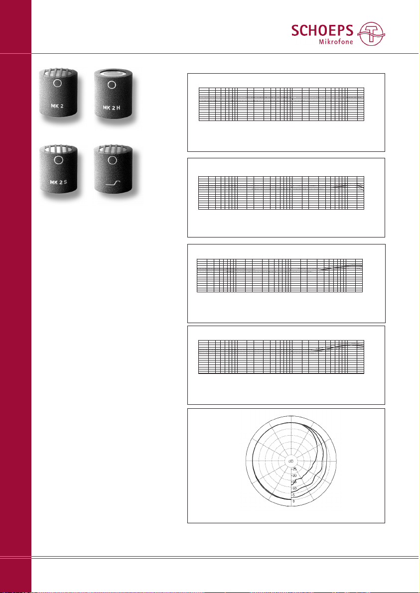
Pressure Transducers (Omnis)
Frequency response curve MK 2 + CMC 6
20 50 100 200 500 1k 2k 5k 10k 20kHz
Frequency response curve MK 2H + CMC 6
20 50 100 200 500 1k 2k 5k 10k 20kHz
Actual miking distances will depend
greatly on characteristics of the
recording environment – especially
size and reverberance – and on personal preference.
Each of these capsules, when used
at appropriate distance, will have a
well-balanced overall response given
the mixture of direct and reflected
sound energy typical of that distance.
Note: Since the capsules have some
directionality at high frequencies, it
is still necessary to aim them with
respect to the sound source, even
though they are ”omnidirectional.”
With the microphone amplifier
CMC 6xt, the frequency range of
these capsules can be extended to
40 kHz.
+10
0dB
-10
-20
+10
0dB
-10
-20
*reverberation radius: the ”critical distance” from the sound source at
which the levels of direct and diffuse sound are equal in a given space.
Frequency response curve MK 2S + CMC 6
20 50 100 200 500 1k 2k 5k 10k 20kHz
Frequency response curve MK 3 + CMC 6
20
50
100 200 500
1k 2k 5k
10k
20kHz
+10
0dB
-10
-20
+10
0dB
-10
-20
MK 2 for free-field placement
(close to the sound source)
MK 2H for use at moderate dis-
tance (at or near the
reverberation radius*)
MK 2S all-purpose capsule for
music and speech, also
for use at moderate distance (at or near the
reverberation radius*)
MK 3 for diffuse-field placement
(distinctly beyond the
reverberation radius*)
MK 3
MK 2S
MK 2 MK 2H
Polar diagram MK 2, -2H, -2S, -3
from outer
to inner:
up to 1 kHz 4 kHz
2 kHz 8 kHz
16 kHz
Capsules
12
Page 13
SCHOEPS GmbH · Spitalstr. 20 · D-76227 Karlsruhe (Durlach) · Tel: +49 721 943 20-0 · Fax: +49 721 943 2050
www.schoeps.de · [email protected]
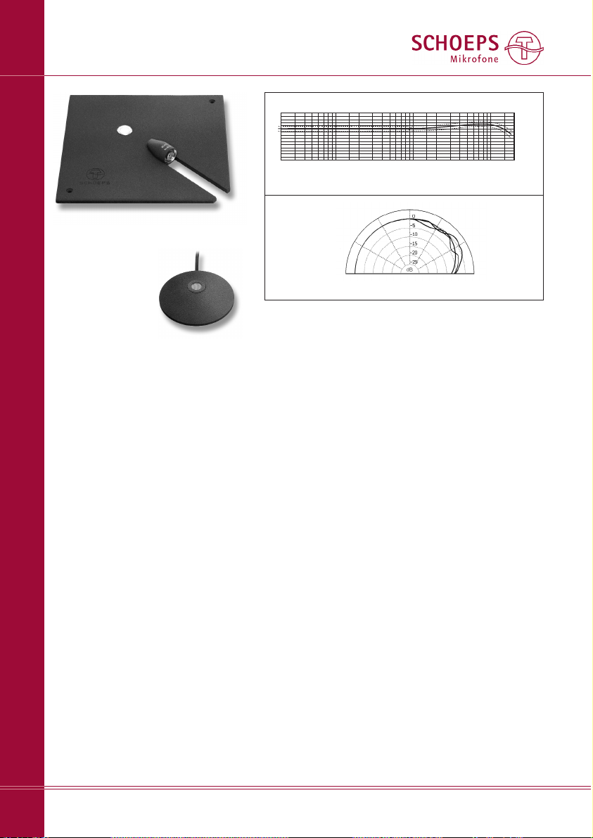
Boundary Layer Microphones
Capsules
13
Frequency response curve BLM 3g, BLM 03Cg + CMC 6
Polar diagram BLM 3g, BLM 03Cg
from outer
to inner:
up to 2 kHz 4 kHz
8 kHz
16 kHz
20 50 100 200 500 1k 2k 5k 10k 20kHz
+10
0dB
-10
-20
– boundary layer capsules
– hemispheric directional pattern
– no coloration of off-axis sound
Suggested applications:
Music (orchestra, including pit orchestra); on-stage; speech.
BLM 03C: Round-table discussions
Note:
The BLM capsules rely on the boundary layer (”pressure zone”) effect.
They will have the frequency response
shown here only when placed on a
floor or another large, flat, rigid surface
which is not covered by thick carpeting
or other sound-absorbent material. For
speech applications such as conference
recording, a table top may suffice.
BLM 3g
BLM 03Cg
Page 14
SCHOEPS GmbH · Spitalstr. 20 · D-76227 Karlsruhe (Durlach) · Tel: +49 721 943 20-0 · Fax: +49 721 943 2050
www.schoeps.de · [email protected]
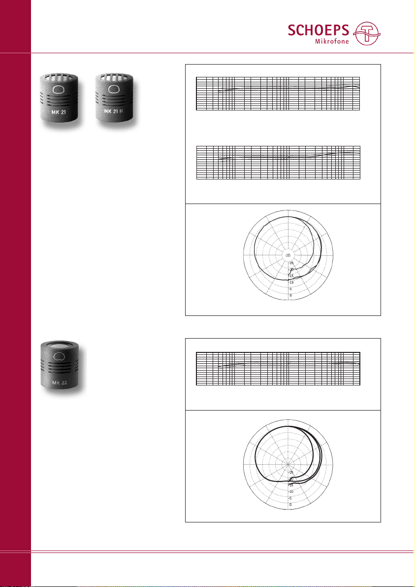
Wide Cardioids / Open Cardioid
Capsules
14
Frequency response curve MK 21 + CMC 6
Polar diagram MK 21, -21H
from outer
to inner:
up to 1 kHz 4 kHz
2 kHz 8 kHz
16 kHz
+10
0dB
-10
-20
20 50 100 200 500 1k 2k 5k 10k 20kHz
Frequency response curve MK 21H + CMC 6
+10
0dB
-10
-20
20 50 100 200 500 1k
2k 5k
10k
20kHz
– wide cardioids
– polar pattern very well maintained
throughout the frequency range
– a favorable compromise between
omni (good low-frequency response)
and cardioid (consistent directional
pattern at all frequencies)
Suggested applications:
MK 21: music (orchestras), spot micro-
phone; vocals; speech
MK 21H: wherever a high-frequency
elevation is desired, esp. non-classical music
MK 21
MK 21H
MK 22
– new kind of directional pattern:
”Open Cadioid”
– optimal combination of classic car-
dioid directionality (MK 4) with the
sonic character of the wide cardioid
(MK 21)
– directional pattern largely constant
throughout the frequency range
Suggested applications:
as spot / soloist’s microphone
20 50 100 200
500
1k 2k 5k 10k 20kHz
Frequency response curve MK 22 + CMC 6
Polar diagram MK 22
von außen
nach innen:
bis 2kHz 4kHz
8kHz
16kHz
+10
0dB
-10
-20
Page 15
SCHOEPS GmbH · Spitalstr. 20 · D-76227 Karlsruhe (Durlach) · Tel: +49 721 943 20-0 · Fax: +49 721 943 2050
www.schoeps.de · [email protected]
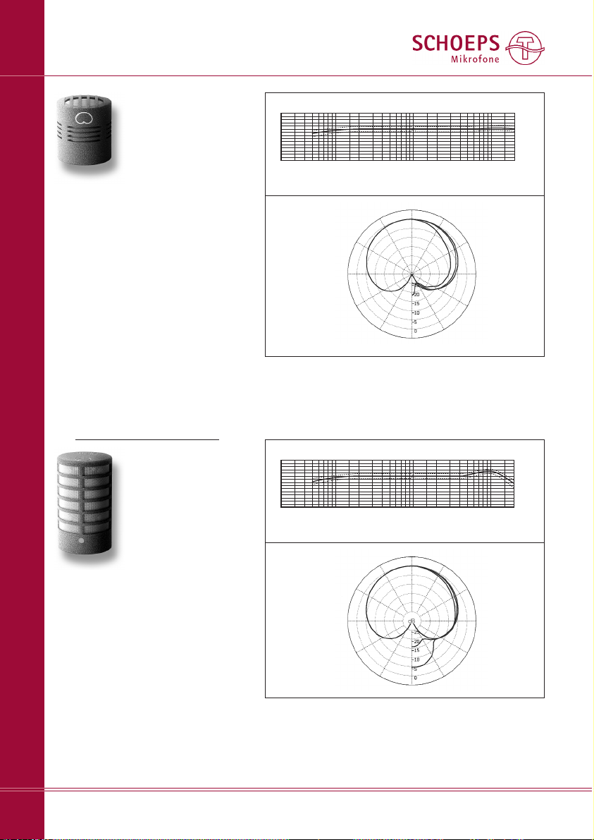
Cardioids
Frequency response curve MK 4V + CMC 6
Polar diagram MK 4V
from outer
to inner:
up to 2 kHz 4 kHz
8 kHz
16 kHz
+10
0dB
-10
-20
20 50 100 200 500 1k 2k
5k
10k 20kHz
MK 4
– standard cardioid with clear sound
quality, free of coloration
– all-purpose capsule for music and
speech
– our best-selling capsule type
– 0° axis is at the tip of the capsule
MK 4V
– cardioid with mild high-frequency
boost
– all-purpose capsule for music and
speech
– highly consistent polar response
– 0° axis is at the side of the capsule
marked by a red dot
Note:
Though not specifically designed for such use, the MK 4V capsule can also be
used on the RC Active Tube or the variable angle joint GVC; when fully
tightened it will rarely be aimed where you intend. On request we will supply
an elastic ring which can be slipped over the threads of the RC or GVC so
that the final turn of the capsule will place it at the desired angle of rotation.
This ring must be kept out of the capsule threads, however.
Capsules
15
Frequency response curve MK 4 + CMC 6
Polar diagram MK 4
from outer
to inner:
up to 1 kHz 4 kHz
2 kHz 8 kHz
16 kHz
20 50 100 200 500 1k 2k 5k 10k 20kHz
+10
0dB
-10
-20
Page 16
SCHOEPS GmbH · Spitalstr. 20 · D-76227 Karlsruhe (Durlach) · Tel: +49 721 943 20-0 · Fax: +49 721 943 2050
www.schoeps.de · [email protected]
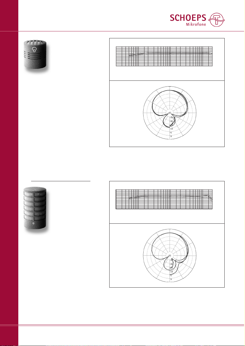
Supercardioids
Frequency response curve MK 41V + CMC 6
Polar diagram MK 41V
from outer
to inner:
up to 2 kHz 4 kHz
8 kHz
16 kHz
+10
0dB
-10
-20
20 50 100 200 500 1k
2k 5k 10k 20kHz
MK 41
– all-purpose capsule for speech and
music recording of all kinds
– well suited for use as the main
microphones for stereo pickup
and/or as ”spot” microphones
– extended, smooth, well-balanced
frequency response
– often used for film and video sound
– has distinct sonic and practical
advantages over most shotgun
microphones
– highly consistent polar response
– 0° axis is at the tip of the capsule
Note:
Though not specifically designed for such use, the MK 41V capsule can also be
used on the RC Active Tube or the variable angle joint GVC; when fully
tightened it will rarely be aimed where you intend. On request we will supply
an elastic ring which can be slipped over the threads of the RC or GVC so
that the final turn of the capsule will place it at the desired angle of rotation.
This ring must be kept out of the capsule threads, however.
Capsules
16
MK 41V
– all-purpose capsule for music and
speech; same uses and advantages
as the MK 41
– 0° axis is at the side of the capsule
marked by a red dot
Frequency response curve MK 41 + CMC 6
Polar diagram MK 41
from outer
to inner:
up to 1 kHz 4 kHz
2 kHz 8 kHz
16 kHz
+10
0dB
-10
-20
20 50
100
200 500 1k
2k 5k
10k
20kHz
Page 17
SCHOEPS GmbH · Spitalstr. 20 · D-76227 Karlsruhe (Durlach) · Tel: +49 721 943 20-0 · Fax: +49 721 943 2050
www.schoeps.de · [email protected]
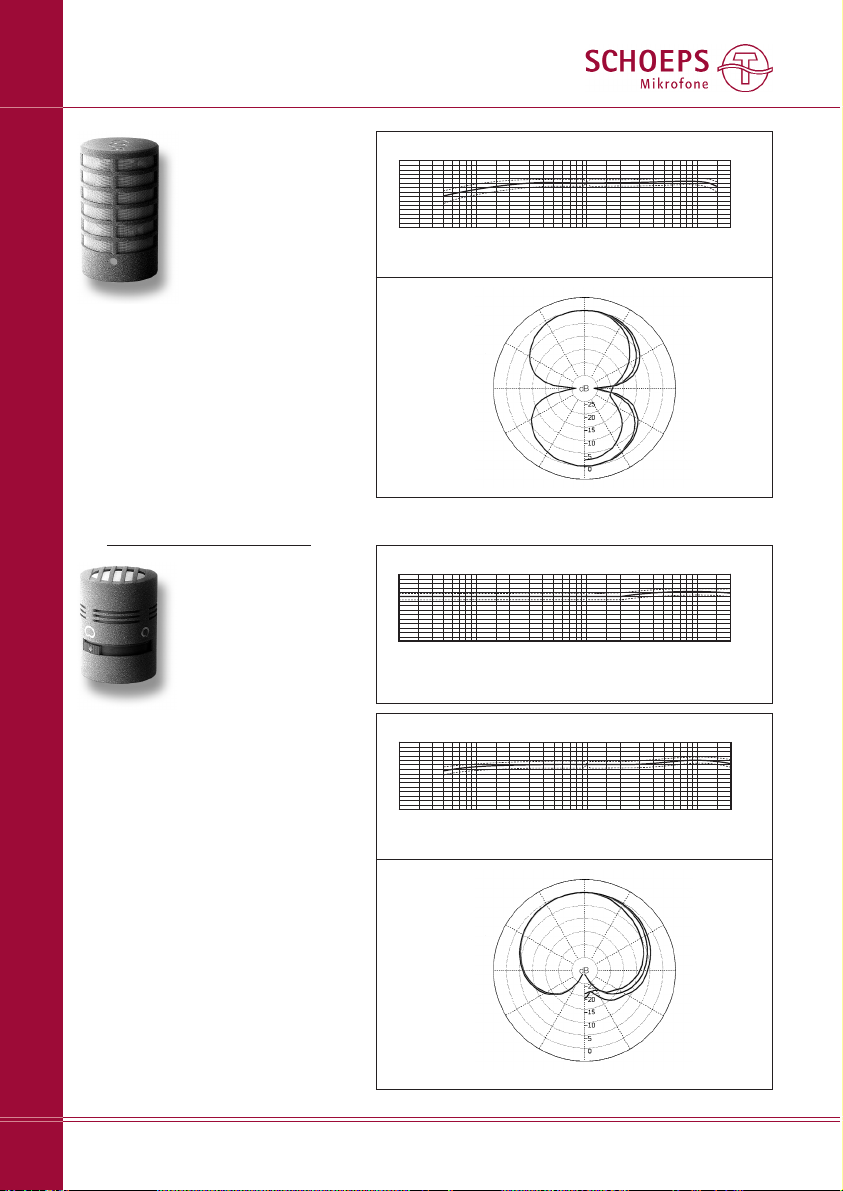
Figure-8 / Switchable Capsule
Frequency response curve MK 8 + CMC 6
Polar diagram MK 8
from outer
to inner:
up to 2 kHz 4 kHz
8 kHz
16 kHz
+10
0dB
-10
-20
20 50 100 200 500 1k 2k 5k 10k 20kHz
MK 5
– mechanically switchable single-dia -
phragm capsule (omni / cardioid)
– smoother, more extended high-fre-
quency response than most other
multi-pattern microphones (e.g.
dual-diaphragm capsules of other
manufacturers)
– a pure pressure transducer when in
the ”omni” setting (flat, extended
low-frequency response without
proximity effect or undue sensitivity
to wind or solid-borne sound)
– slightly brighter than the MK 2H
(omni) or MK 4 (cardioid)
Intermediate switch positions are
mechanically possible, but are not
reproducable or recommended.
Capsules
17
Frequency response MK 5 ”omni” + CMC 6
Polar diagram identical to that of MK 2, -2H, -2S, -3
+10
0dB
-10
-20
20 50 100 200 500 1k 2k 5k 10k 20kHz
Frequency response MK 5 ”cardioid” + CMC 6
Polar diagram MK 5
from outer
to inner:
up to 2 kHz 4 kHz
8 kHz
16 kHz
+10
0dB
-10
-20
20
50 100 200 500 1k 2k 5k 10k 20kHz
”cardioid” position
MK 8
– figure-8 (”bidirectional”) pattern
– clear sound quality, free of coloration
– for M/S and Blumlein stereo
– highly consistent frequency and
polar response
– response essentially free of off-axis
peaks like a good ribbon microphone
(but not as delicate physically)
– lateral pickup
Page 18
SCHOEPS GmbH · Spitalstr. 20 · D-76227 Karlsruhe (Durlach) · Tel: +49 721 943 20-0 · Fax: +49 721 943 2050
www.schoeps.de · [email protected]
Cardioids for Close Pickup
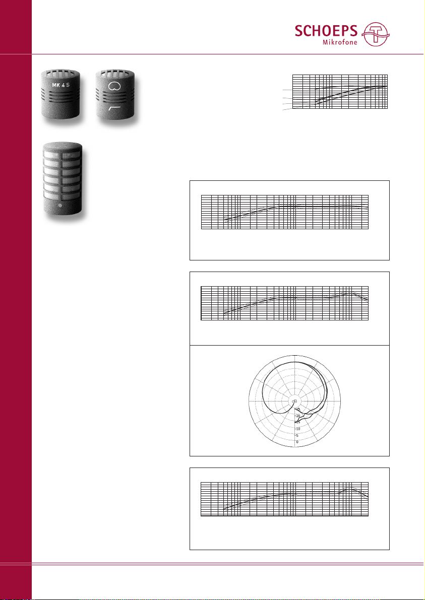
Frequency response curve MK 4S + CMC 6
Polar diagram identical to that of the MK 4
+10
0dB
-10
-20
20 50 100 200 500 1k 2k 5k 10k 20kHz
When a directional microphone is
used close to a sound source, its lowfrequency response increases greatly.
This ”proximity effect” gives voices an
artificial ”boomy” quality which is
sometimes useful as a special effect,
but it reduces intelligibility and causes
listener fatigue.
To avoid this problem and to reduce
the effects of breath noise and popping on consonants, low-frequency
filtering can be applied (e.g. the CUT 1
Active Filter) or special speech capsules
with reduced low-frequency sensitivity
can be used. These same measures
also help to suppress low-frequency
environmental noise.
MK 4S
– for close pickup (ca. 50 cm = 20")
MK 40
– for close pickup (ca. 50 cm = 20")
– high-frequency emphasis for better
speech intelligibility in reveberant
venues (e.g. churches)
MK 4VXS
– for extremely close pickup (under
10 cm = less than 4")
– lateral pickup
MK 40MK 4S
Capsules
18
MK 4VXS
Frequency response curve MK 40 + CMC 6
Polar diagram MK 40
from outer
to inner:
up to 2 kHz 4 kHz
8 kHz
16 kHz
+10
0dB
-10
-20
20 50 100 200 500 1k 2k 5k 10k 20kHz
20 50 100 200 500 1k
+10
0dB
-10
-20
MK 4 standard
cardioid
MK 4S and MK 40
MK 4A
MK 4VXS
Frequency response curve MK 4VXS + CMC 6
Polar diagram essentially identical to that of the MK 4V
+10
0dB
-10
-20
20 50 100 200 500
1k
2k
5k
10k 20kHz
The frequency response curves shown on these pages were ob tained
at the usual one-meter equivalent measuring distance. They show
low-frequency rolloffs which will suppress low-frequency en viron mental noise. When these capsules are used at the indicated working
distances, proximity effect and the low-frequency rolloff will balance each other out, creating a natural-sounding pickup of the voice.
Low-frequency
attenuation of
cardioids for
close pickup
Page 19
SCHOEPS GmbH · Spitalstr. 20 · D-76227 Karlsruhe (Durlach) · Tel: +49 721 943 20-0 · Fax: +49 721 943 2050
www.schoeps.de · [email protected]
Cardioids / Supercardioid for Close Pickup
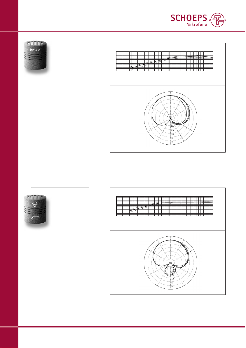
Frequency response curve MK 41S + CMC 6
Polar diagram MK 41S
from outer
to inner:
up to 2 kHz 4 kHz
8 kHz
16 kHz
+10
0dB
-10
-20
20 50 100 200 500 1k 2k 5k 10k 20kHz
MK 41S
– supercardioid for close pickup
(under 50 cm)
– considerable low-frequency
attenuation
– compensates for proximity effect
– suggested application: speech in a
loud environment
Capsules
19
MK 4A
– for extremely close pickup (under
10 cm = less than 4")
– deliberate 10 dB reduction in
sensitivity
– especially well suited for hand-held
radio microphones made by AUDIO
Ltd. (England)
Polar diagram MK 40
from outer
to inner:
up to 1 kHz 4 kHz
2 kHz 8 kHz
16 kHz
Frequency response curve MK 4A + CMC 6
+10
0dB
-10
-20
20 50 100 200 500 1k 2k 5k 10k 20kHz
Page 20
SCHOEPS GmbH · Spitalstr. 20 · D-76227 Karlsruhe (Durlach) · Tel: +49 721 943 20-0 · Fax: +49 721 943 2050
www.schoeps.de · [email protected]
Specifications
Capsules
20
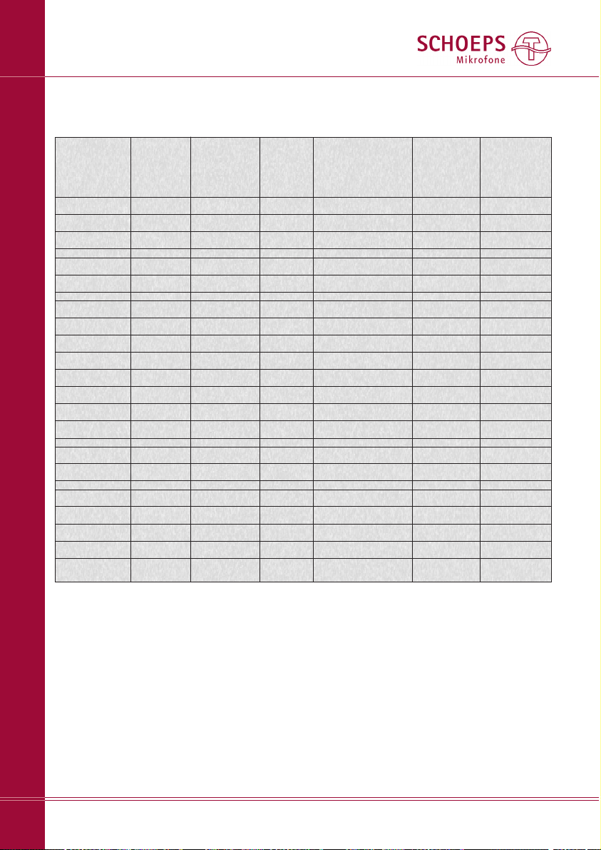
Capsule Type Polar Frequency Range Sensitivity Equivalent Noise Level Signal-to-Noise Max. SPL
Pattern CCIR A-weighted Ratio (0.5% THD)
A-weighted
MK 2 omni 20 Hz – 20 kHz* 15 mV/Pa 23 dB 11 dB 83 dB 130 dB
MK 2H omni 20 Hz – 20 kHz* 15 mV/Pa 23 dB 12 dB 82 dB 130 dB
MK 2S omni 20 Hz – 20 kHz* 12 mV/Pa 24 dB 12 dB 82 dB 132 dB
MK 3 omni 20 Hz – 20 kHz* 10 mV/Pa 26 dB 14 dB 80 dB 134 dB
BLM 3g hemisphere 20 Hz – 20 kHz 19 mV/Pa 23 dB 12 dB 82 dB 128 dB
BLM 03 Cg hemisphere 20 Hz – 20 kHz 19 mV/Pa 23 dB 12 dB 82 dB 128 dB
MK 21 wide cardioid 30 Hz – 20 kHz* 13 mV/Pa 25 dB 15 dB 79 dB 132 dB
MK 21H wide cardioid 30 Hz – 20 kHz* 10 mV/Pa 26 dB 16 dB 78 dB 134 dB
MK 22 Open Cardioid 40 Hz – 20 kHz* 14mV/Pa 23 dB 14 dB 80 dB 131 dB
MK 4 cardioid 40 Hz – 20 kHz* 13 mV/Pa 24 dB 15 dB 79 dB 132 dB
MK 4V cardioid 40 Hz – 20 kHz 13 mV/Pa 24 dB 14 dB 80 dB 132 dB
MK 41 supercardioid 40 Hz – 20 kHz* 13 mV/Pa 24 dB 16 dB 78 dB 132 dB
MK 41V supercardioid 40 Hz – 20 kHz 13 mV/Pa 24 dB 15 dB 79 dB 132 dB
MK 8 figure-8 40 Hz – 16 kHz 10 mV/Pa 26 dB 18 dB 76 dB 134 dB
MK 5 omni 20 Hz – 20 kHz* 11 mV/Pa 26 dB 14 dB 80 dB 133 dB
cardioid 40 Hz – 20 kHz 13 mV/Pa 25 dB 16 dB 78 dB 132 dB
MK 4S cardioid 80 Hz – 20 kHz 13 mV/Pa 24 dB 15 dB 79 dB 132 dB
MK 40 cardioid 80 Hz – 20 kHz 18 mV/Pa 22 dB 13 dB 81 dB 129 dB
MK 4A cardioid close pickup 3 mV/Pa 29 dB 18 dB 76 dB 144 dB
MK 4VXS cardioid close pickup 10 mV/Pa 24 dB 14 dB 80 dB 134 dB
MK 41S supercardioid 80 Hz – 20 kHz 13 mV/Pa 24 dB 15 dB 79 dB 132 dB
Specifications for Complete Microphones: MK -- Capsules with CMC 6 Microphone Amplifier
* When the CMC 6 xt microphone amplifier is used with axially addressed capsules, the frequency response extends
beyond 40 kHz.
A word about signal-to-noise specifications for studio microphones: The standard method, which we follow, is really just
an alternate way of stating a microphone's equivalent noise
level. It is designed to allow comparison of noise floor levels
for different microphones. Unlike the signal-to-noise specifications for other types of audio equipment, which give the ratio
of a component's clipping point to its noise floor, these values
do not indicate a microphone's entire available dynamic range.
Instead, the values are measured with reference to a standard
sound pressure level of 1 Pascal (1 Pa = 94 dB SPL). But the
actual maximum SPL capability of any usable microphone
exceeds that reference level substantially. The signal-to-noise
specifications of our microphones would be 35 to 40 dB (!)
greater if the ”hi-fi” approach were used.
The use of ”A” weighting when specifying the equivalent
noise level of microphones is another often-misunderstood
aspect of the standards. ”A” weighting yields a distinctly
lower noise specification – often by 10 dB or thereabouts –
and this figure, of course, becomes the one most often cited
in advertising. But the CCIR weighted noise level may well be
a more accurate indicator of a microphone's perceived noise
level in practice.
Page 21

Care of Colette Series Condenser
Microphone Capsules
Please be careful to avoid placing capsules in
a dusty environment. Keep them in their cases
(or in the wood case of the microphone amplifier) when not in use, since any dust that gets
inside the capsules can adversely affect their
functioning. In combination with humidity it
can lead to condensation and thus popping
and crackling noises (often described as ”frying
sounds”).
What to do if …
the microphone is noisy (clicks and pops) in high
humidity?
– If the microphone is brought from the cold
outdoors into a warm environment, snapping
or clicking noises can result from the condensation of moisture. In such a case the
microphone should be given time to reach
room temperature, and as a rule it will then
perform flawlessly.
– Sometimes dirt can get into the contacts at
the end of the microphone amplifier or of
an Active Accessory where the capsule is
attached; this, too, can cause impulse noise.
You can clean the contacts yourself by using
compressed air (without lubricant) from an
aerosol can. If that doesn't help, you can
scrub them with a new, clean toothbrush
dipped in isopropyl alcohol, holding the
microphone amplifier or Active Accessory
so that the contacts face downward. Shake
off any extra fluid; under no circumstances
can it be allowed to flow into the amplifier!
Be careful to wipe the contacts dry.
If this treatment does not eliminate the noise,
it is possible that dirt has gotten inside the
capsule itself – in which case the capsule must
be sent back to the factory for cleaning. We
strongly urge customers not to open a capsule or attempt to clean it themselves. Doing
so would also void all warrantees. Neither
should the contact rings of a capsule be
cleaned with any kind of liquid. Windscreens
are recommended when micro phones have to
be used in dirty or dusty environments in order
to avoid problems of the kind described above.
Possible Problems
Wind Noise and Polar Pattern
Noise problems may be a consideration when
choosing a microphone pattern (directional
characteristic) for a given set of recording conditions. Pressure transducers are considerably
less prone than pressure gradient transducers
(such as cardioids or supercardioids) to pick
up noise from air currents or mechanical
vibra tion. SCHOEPS omnidirectional capsules
are pressure transducers, as are our switchablepattern capsules in their omnidirectional settings. If strong wind is anticipated, or physical
vibration of the microphone, perhaps a pressure
transducer such as the MK 2 S should be used
instead of a cardioid or supercardioid. The distance between the microphone and the sound
source should then be reduced by about half
if possible.
Wind Noise and Windscreens
Air motion (wind, vocal ”popping” on sung
or spoken consonants, motion of the microphone on a boom arm, or air currents due to
heating or air conditioning systems) can cause
noise that should always be dealt with. Even if
it doesn't cause overload, it will detract from
the clarity of sound. A wind or pop screen
should be used, but should be chosen carefully
to avoid changing the microphone's characteristics too much. Many screen types which are
effective at reducing wind noise also have a
tendency to reduce a microphone's directionality and/or its high-frequency response. Baskettype windscreens are generally more effective
than foam-type windscreens when directional
capsules are being used, and their main side
effect is to create some unevenness in frequency
response (see our main catalog for details).
Vibration
If noise from mechanical vibration enters a
stand- or boom-mounted microphone, a shock
mount (elastic suspension) should be used, and
SCHOEPS GmbH · Spitalstr. 20 · D-76227 Karlsruhe (Durlach) · Tel: +49 721 943 20-0 · Fax: +49 721 943 2050
www.schoeps.de · [email protected]
Care and Maintenance / Possible Problems
Capsules
21
Page 22

a loop of slack cable should be isolated and
tied off so that it does not become another
way for vibrations to reach the microphone.
Unlike a wind screen, a shock mount will not
affect the characteristics of a microphone. In
many kinds of work it is well justified to use a
shock mount ”by default.”
Overload
When dealing with problems of overload, it is
useful to think of your recording equipment
as a series of circuit stages. The goal is to find
the first stage that is being overloaded, and to
attenuate the signal at the input to that stage.
Reducing the gain at any earlier stage would
add unnecessary noise, while reducing it at a
later stage would not solve the problem.
A condenser microphone represents two circuit stages: the capsule and the amplifier. In
practice, capsules are rarely overloaded except
by explosions or very strong wind; the only
sound pressure levels that could overload a
SCHOEPS capsule are so extreme – ca. 150 dB
SPL – that they would quickly damage human
hearing. Properly powered SCHOEPS CMC
amplifiers can normally handle 130+ dB sound
pressure levels, depending on the capsule type.
Such levels rarely occur in unamplified sound,
though their equivalents can be caused by wind
when directional capsules are used. In addition,
proper powering should not be taken for
granted; insufficient or incorrect microphone
powering has proved to be the cause of many
otherwise mysterious “overload” problems.
If wind and powering can be excluded as
possible issues, however, overload is far more
likely to occur in the input circuitry of mixers,
preamps or recorders than in SCHOEPS CMC-
series microphones. This is true particularly
with consumer audio equipment, though even
today some professional equipment is still
designed primarily for use with dynamic micro phones or with earlier, less sensitive condenser
microphones. If an input sensitivity control is
available, it should be set low enough to avoid
input overload, but not so low as to cause
excess noise – though a few dB of extra hiss is
preferable to the risk of hard clipping. Level
meters and overload indicators don’t generally
detect input overload even in fully professional
equipment; they operate only at later stages
of the circuitry.
If overload occurs where powering, high
sound pressure levels and wind are not the
problem and an input sensitivity control cannot be turned down, the next logical step is
to plug in a balanced resistive ”pad” (attenuator) such as the SCHOEPS MDZ 10 or MDZ 20
at the preamp input. If the sound quality
improves, leave the pad in place; as long as a
microphone isn’t being overloaded, it is always
better to pad the preamp input than the microphone. Only if there are extreme sound pressure levels should a capacitive attenuator
(SCHOEPS DZC 10 or DZC 20) be used.
Low-frequency disturbances such as wind
and solid-borne vibration may not be directly
audible as such, but infrasonic noise can still
cause overload in some stage of the signal
chain. A windscreen then becomes the first
line of defense. But low-frequency noise can
also be effectively suppressed in SCHOEPS
Colette microphones with the Active Filters
CUT 1 or CUT 2, inserted between the capsule
and amplifier. These filters have the side effect
of raising a CMC amplifier’s gain to that of the
+5 dB option (see pages 4 and 5), but given
the enormous levels of noise which can be
generated by wind, they are helpful far more
often than not. Alternatively, the simpler lowcut filters LC 60 or LC 120 can be placed at
the input of a phantom-powered preamp.
Overload which does not otherwise seem
to make sense may actually be a symptom of
incorrect or inadequate microphone powering.
Powering systems and their requirements are
discussed near the beginning of this manual
on page 5.
The least expensive, most helpful trouble shooting tools are:
– a known good microphone cable
– a simple pop screen such as the SCHOEPS
B 5 (or for outdoor recording, a wind
screen such as the SCHOEPS W 5)
– a balanced, in-line resistive attenuator (”pad”)
such as the SCHOEPS MDZ 10 or MDZ 20
– an ordinary multimeter or the SCHOEPS
PHS 48 phantom power tester
SCHOEPS GmbH · Spitalstr. 20 · D-76227 Karlsruhe (Durlach) · Tel: +49 721 943 20-0 · Fax: +49 721 943 2050
www.schoeps.de · [email protected]
Possible Problems
Capsules
22
Page 23

Warranty
We guarantee our products for a period of
twenty-four months, except for batteries.
The guarantee period begins on the date of
purchase.
Please provide your bill of sale in all cases as
proof of guarantee; without it, repairs will be
undertaken only at the owner's expense.
We reserve the right to satisfy all warranty
requirements regarding defects of workmanship or materials by means of repair or partial
or complete replacement of the product, at
our sole discretion.
Excluded from this guarantee are defects due
to misuse (e.g. incorrect operation; mechanical
damage), abuse or “Acts of God.” This guarantee is nullified in the event of tampering by
unauthorized persons or agencies.
To secure your rights under this guarantee,
send the product with proof of purchase and
a precise description of the malfunction, at your
expense, either to SCHOEPS (if you are a customer in Germany), or to our representative
(if you are a customer outside of Germany).
Prior to sending your defective product for
repair, please contact your local dealer or distributor for instructions. In exceptional cases
you can, by prior arrangement with SCHOEPS,
send the product directly to us from a foreign
country. However any return shipment must
then be prepaid; this tends to cause delays,
especially for non-warranty service. Full payment must be made before a repaired item
can be returned to the customer.
This guarantee does not affect any contractual
agreements which may exist between the buyer
and seller of the equipment.
This guarantee is world-wide.
Declaration of Conformity – CE-Mark
The CE-mark guarantees that all products
conform to relevant standards approved by
the European Community. The products
described in this User Guide comply with current, relevant standards when used with cables
from SCHOEPS.
Relevant directives:
EMC Directive: 89/336/EEC, amended by
92/31/EEC and 93/68/EEC
Relevant standards:
EN 55 103-1, -2 and those which are referred
to by them.
SCHOEPS GmbH · Spitalstr. 20 · D-76227 Karlsruhe (Durlach) · Tel: +49 721 943 20-0 · Fax: +49 721 943 2050
www.schoeps.de · [email protected]
Warranty / Declaration of Conformity
Capsules
23
Page 24

Subject to change without notice.
Not responsible for errors or omissions.
091102
Technik
Schall
SCHOEPS GmbH
Spitalstrasse 20
D-76227 Karlsruhe (Durlach)
Germany
Tel: +49 721 943 20-0
Fax: +49 721 943 2050
www.schoeps.de
[email protected]
 Loading...