

Page 1
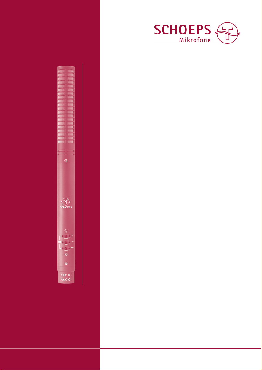
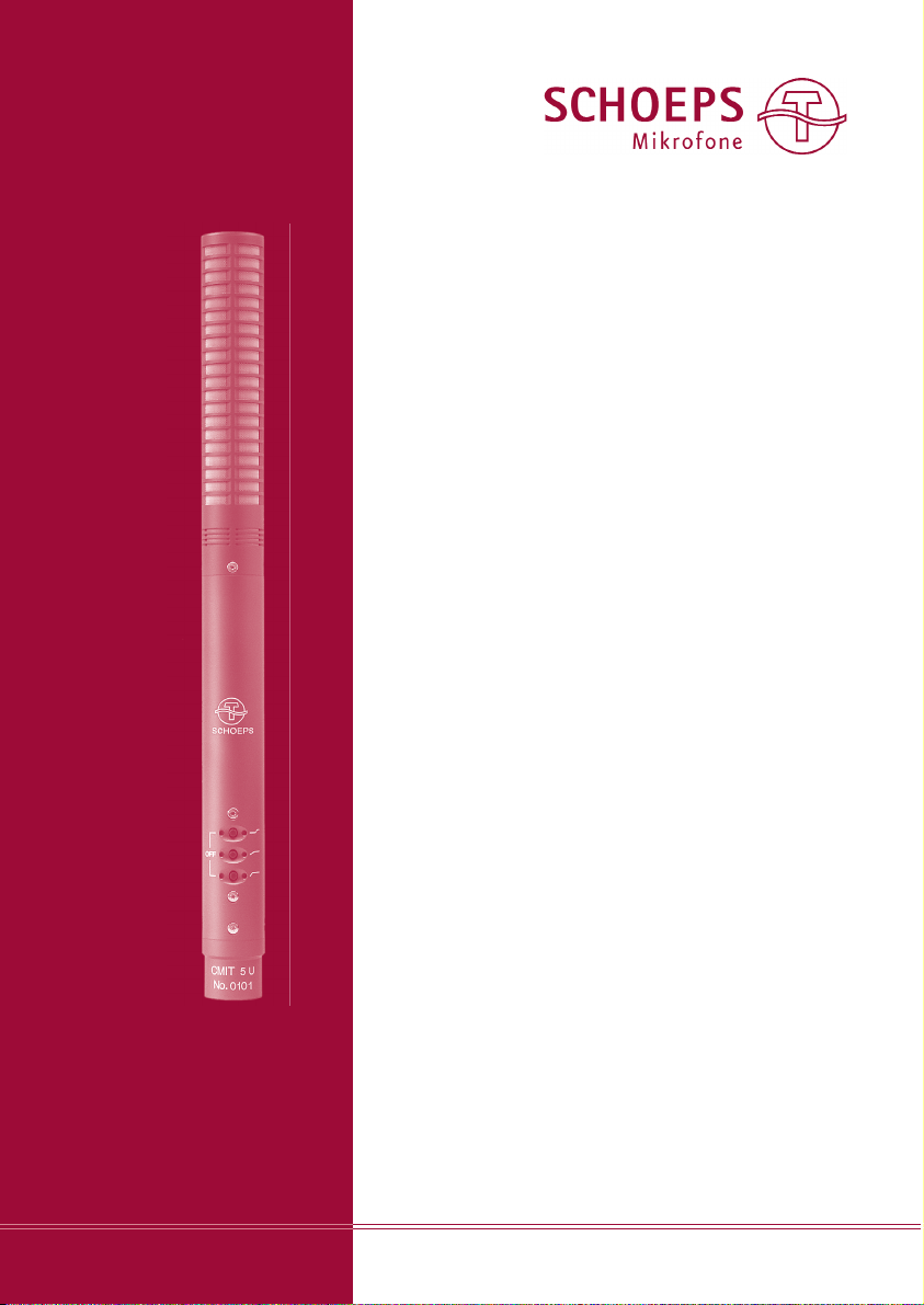
CMIT 5 U
Rohr-Richtmikrofon
Interference-Tube ”Shotgun” Microphone
Bedienungsanleitung
User Guide
Inhaltsverzeichnis
Seite
Charakteristika / Zubehör 2
Einsatzbereiche 4
Filter 5
Inbetriebnahme 6
Phantomspeisung 7
Vermeidung von Störungen 8
Pflege und Wartung 10
Technische Daten 11
Blockschaltbild 12
Garantie 13
Table of Contents page 15
Page 2
SCHOEPS GmbH · Spitalstr. 20 · D-76227 Karlsruhe (Durlach) · Tel: +49 721 943 20-0 · Fax: +49 721 943 2050
www.schoeps.de · [email protected]
Rohr-Richtmikrofon CMIT 5 U
2
Deutsch
Sehr geehrter Kunde,
herzlichen Glückwunsch zu Ihrer Entschei dung
für das Rohr-Richtmikrofon CMIT 5 U von
SCHOEPS.
Damit es einwandfrei arbeiten kann, sollten
einige Punkte beachtet werden. Diese finden
Sie auf den nächsten Seiten, gefolgt von
Hinweisen zu den Themen Wind und Übersteuerungen sowie zur Pflege.
Im Anhang finden Sie die technischen Daten.
Charakteristika des CMIT 5 U
Das CMIT 5 U ist ein klassisches Konden sa tor mikrofon (Druckgradientenempfänger), dem
ein akustisches Interferenzrohr vorangestellt ist.
Dieses bewirkt bei mittleren und hohen Fre quenzen, dass seitlich der Mikrofon achse einfallender Schall noch weiter unterdrückt wird
als bei Supernieren, den am stärksten richtenden “kurzen” Richtmikrofonen. Hierdurch
ent steht ein keulenförmiges Richt diagramm.
Das CMIT 5 U zeichnet sich aus durch:
– ein Interferenzrohr, das schon ab einer rela-
tiv niedrigen Frequenz wirkt, ohne dass die
Richt keule bei hohen Frequenzen zu schmal
wird,
– eine hervorragende Klangqualität (daher ist
es universell einsetzbar, z.B. auch als Stütz -
mikrofon bei Musik auf nah men),
– sein geringes Gewicht,
– seine geringe Windempfindlichkeit,
– gleiche Richtwirkung in der Horizontalen und
Vertikalen (rotationssymmetrische Richt keule),
– drei zuschaltbare Filter,
– einen symmetrischen, niederohmigen, über-
tragerfreien Ausgang, der den störungsfreien
Betrieb auch an langen Kabeln erlaubt.
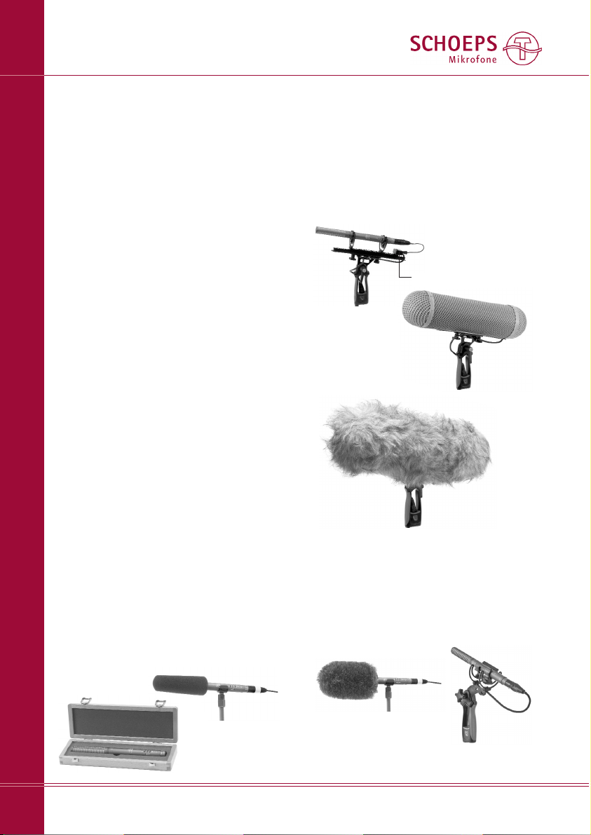
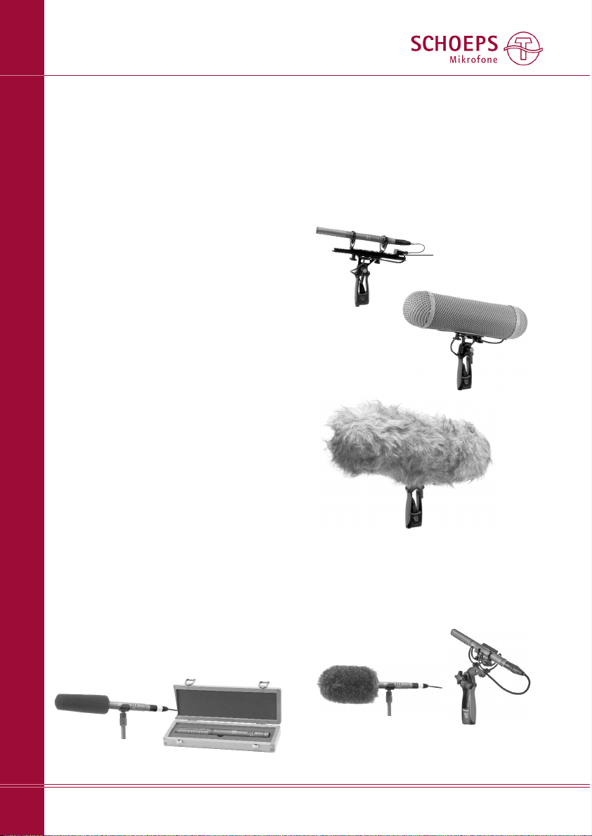
Rycote
12cm “Softie”
Rycote “Softie Lyre Mount”;
erhältlich ab 06/09
Fellüberzug WJ CMIT (“Windjammer”)
für WSR CMIT U
Connbox
Lieferumfang:
Zusätzlich erhältliches Zubehör:
Für Mono:
Windschutzkorb WSR CMIT LU (Ø 100mm;
beinhaltet: elastische Aufhängung, Pistolen griff, Kabel und Connbox
Windjammer WJ CMIT
Nur in Deutschland bei SCHOEPS erhältlich:
WSR CMIT U
W 140
SG 20
Holz-Etui
Page 3
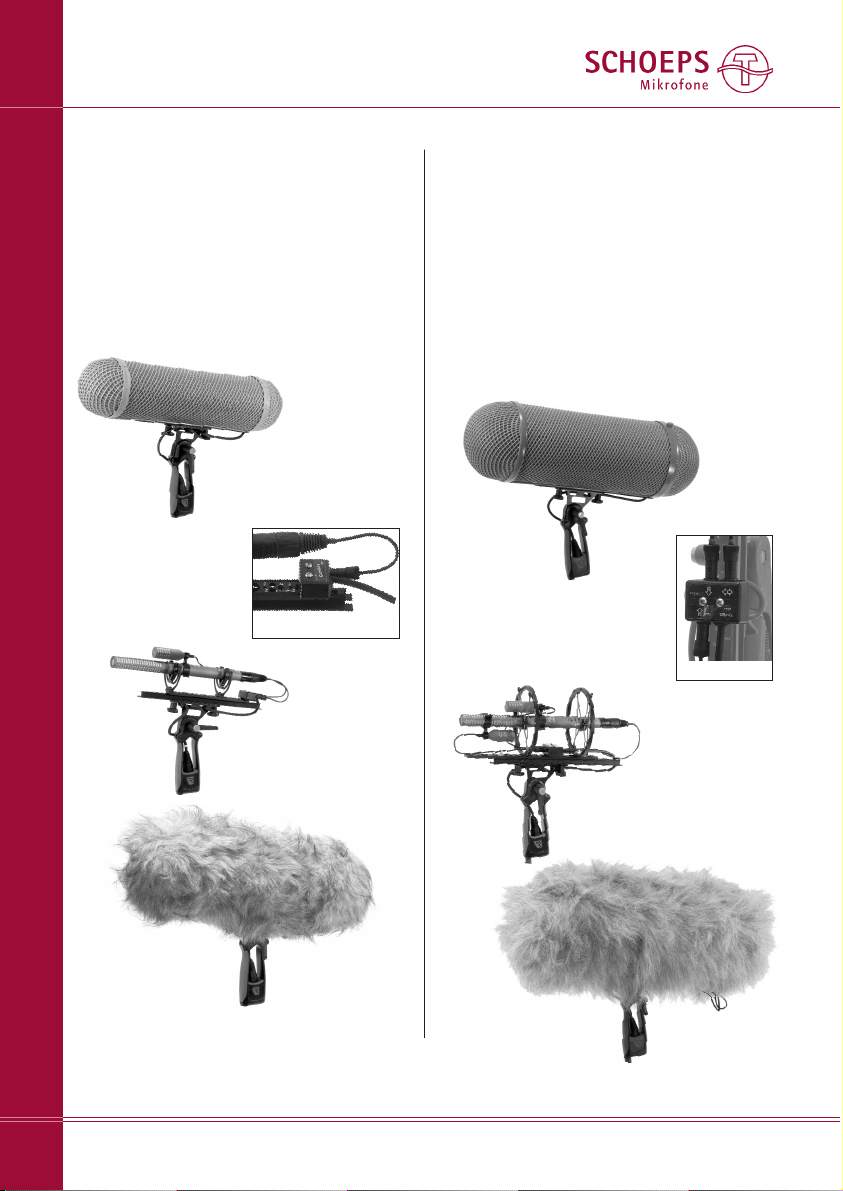
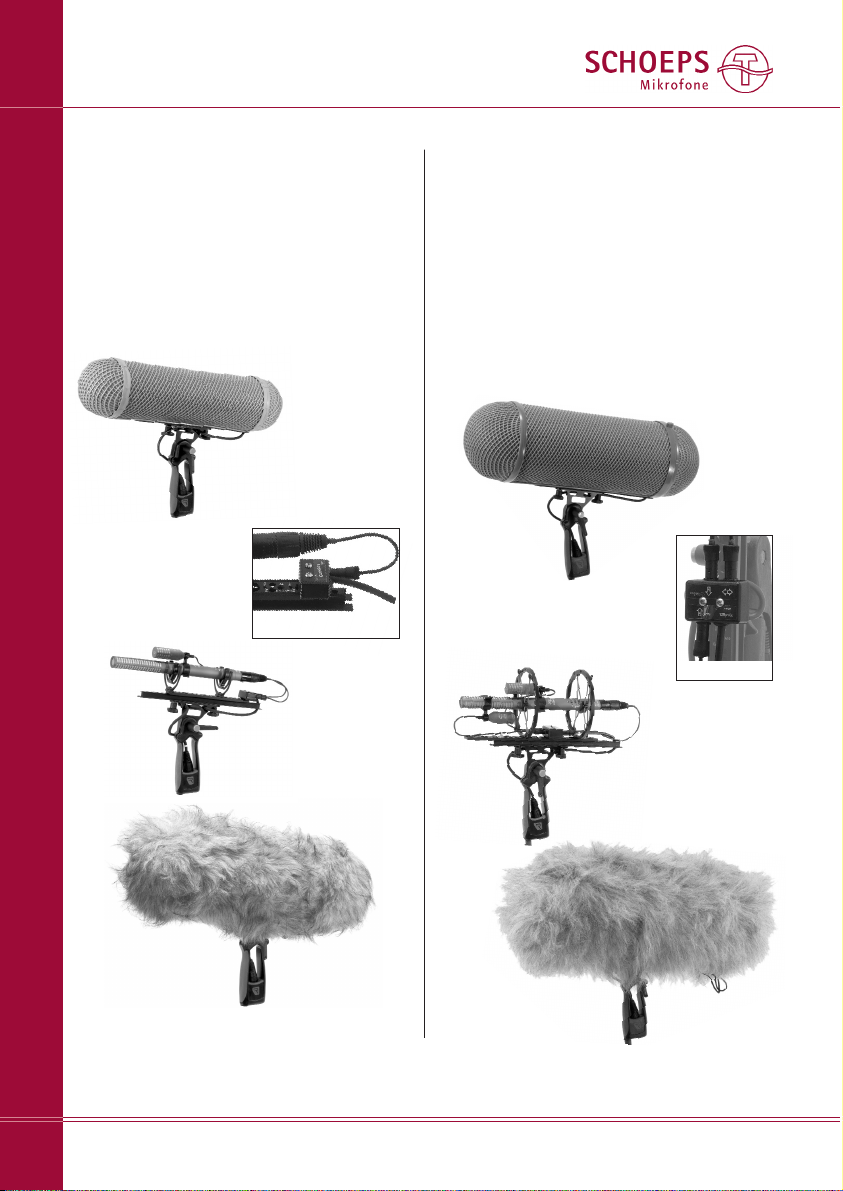
WSR MS CMIT U mit Windjammer
WJ CMIT
Connbox
SCHOEPS GmbH · Spitalstr. 20 · D-76227 Karlsruhe (Durlach) · Tel: +49 721 943 20-0 · Fax: +49 721 943 2050
www.schoeps.de · [email protected]
Zubehör
3
Deutsch
Für MS-Stereo:
Windschutzkorb WSR MS CMIT LU (Ø 100mm;
beinhaltet: elastische Aufhängung, Pistolen griff, Kabel und Connbox), Doppelklammer
KMSC (siehe Seiten 3 und 5),
Windjammer WJ CMIT (muss separat bestellt
werden)
Ferner wird ein Mikrofon mit Acht-Charak te r is tik benötigt, das CCM 8Lg.
Connbox
Windschutzkorb
WSR MS CMIT LU
Windschutzkorb
WSR DMS CMIT LU
Für Surround nach dem Doppel-MSAufnah meverfahren:
Windschutzkorb WSR DMS CMIT LU (Ø 150mm;
beinhaltet: elastische Aufhängung mit Pisto lengriff und Connbox), 2× Klammer KMSC,
Windjammer WJ DMS CMIT (muss separat
bestellt werden)
Ferner werden folgende Mikrofon benötigt:
1× ”Niere” CCM 4Lg,
1× ”Acht” CCM 8Lg.
WSR DMS CMIT LU mit Windjammer
WJ DMS/ORTF
Page 4
Einsatzbereiche des CMIT 5 U
Das CMIT 5 U ist das ideale Mikrofon für Reportagen, Inter views oder Dialoge bei Film- und
Fern seh auf nah men.
Wie kaum ein anderes Rohr-Richtmikrofon
kommt es auf Grund des ausgeglichenen Fre quenzgangs und der nur mäßigen Frequenz ab hän gig keit des Polardiagramms (vergleichsweise
geringe Unter schiede zwischen tiefen und
hohen Frequen zen) auch für den Einsatz als
Stützmikrofon bei Musik auf nahmen in Frage.
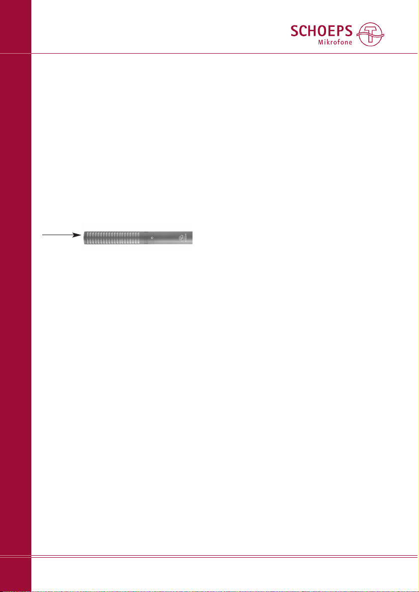
Die Besprechung erfolgt in Richtung seiner
Achse:
Bitte achten Sie darauf, dass alle Schall ein trittsöff nungen (Schlitze) des Mikrofons im Betrieb
frei sind. Das gilt es insbesondere beim Ein satz
in Windschutzkörben, bei MS oder Doppel-MS
zu beachten, wo eine oder mehrere Klammern
im Einsatz sind.
Das Verdecken von Schlitzen kann zu einer
Ver änderung des Klangs und der Richt wir kung
führen.
Hier sind einige wissenswerte Aspekte zu RohrRicht mikrofonen im Allgemeinen und zum
CMIT 5 U im Besonderen:
1. Rohr-Richtmikrofone können bei vorgege be ner Länge entweder hinsichtlich der Richt wir kung oder in Bezug auf den Klang optimiert
werden. Beim CMIT 5 U gab SCHOEPS dem
Klang Priori tät.
2.1 Reflektionen und Nachhall tragen zur Aus prägung der Klangfarbe einer Schallquelle bei.
Weil bei hohen Frequenzen der Raumbereich,
aus dem Schall aufgenommen wird, im Ver gleich zu tiefen Frequenzen kleiner ist (abfal len der Diffusfeld-Frequenzgang), kann ein dumpfer Klangeindruck entstehen, der bei Einsatz
eines Wind schutzes durch dessen Dämp fung
der hohen Fre quen zen noch verstärkt wird.
Dem kann beim CMIT 5 U durch Zuschalten
eines Filter mit Höhen anhebung entgegen gewirkt werden. Dies kommt auch der Sprach ver ständ lichkeit zugute.
2.2 Häufig finden sich im Polardiagramm von
Rohr-Richt mikrofonen schmale Nebenkeulen,
die in Räumen bei Bewegungen der Schall quelle oder des Mikrofons störende, kammfilterähnliche Effekte bewirken können. Beim
SCHOEPS Rohr-Richtmikrofon CMIT 5 U sind
die Nebenkeulen besonders bedämpft.
2.3 Da außerhalb der Achse auftreffender
Schall weniger brillant aufgenommen wird als
auf der Achse, muss das Mikrofon stets exakt
nachgeführt werden, was z.B. bei schnellen
Bewegungen eines Schau spielers nicht immer
einfach ist. Auch bei optimaler Nach führung
werden benachbarte Akteure und auch die
Umgebungsgeräusche weniger brillant aufgenommen.
3. Da Rohr-Richtmikrofone häufig im Freien und
an Angeln betrieben werden, sollten sie – wie
das CMIT 5 U – über eine Tiefenabsenkung
verfügen, mit der sich Wind- und Greifgeräu sche unterdrücken lassen.
Wenn ein richtendes Mikrofon nahe einer
Schall quelle positioniert wird, werden die tiefen
Frequenzen und die unteren Mitten angehoben.
Um eine übertriebene Bass wiedergabe zu ver meiden, sollte ein Rohr- Richt mikro fon deshalb
ebenso ein Filter zur Kom pen sa tion des Nah besprechungseffekts haben. Diese beiden
Anforderun gen betreffen jedoch unterschied liche Frequenz berei che und Filterkurven, wes halb ein einzel nes Tiefenfilter bestenfalls ein
Kompromiss sein kann. Das SCHOEPS CMIT 5 U
verfügt deshalb über ein schaltbares Tiefen filter mit zwei unterschied lichen Charak teris ti ken: eines mit steilem Abfall zur Unterdrückung
von dröhnenden Raumgeräuschen sowie von
Wind- oder Greifgeräuschen und ein langsamer
abfallendes, das in der Frequenz weiter hinauf
reicht, um den Nahheitseffekt zu kompensieren.
4. Auch wenn sie den Hallradius (s.S. 11) für
höhere Fre quen zen vergrößern, ist der Einsatz
von Rohr-Richt mikro fo nen vor allem innerhalb
SCHOEPS GmbH · Spitalstr. 20 · D-76227 Karlsruhe (Durlach) · Tel: +49 721 943 20-0 · Fax: +49 721 943 2050
www.schoeps.de · [email protected]
Einsatzbereiche / Eigenschaften
4
Deutsch
Page 5
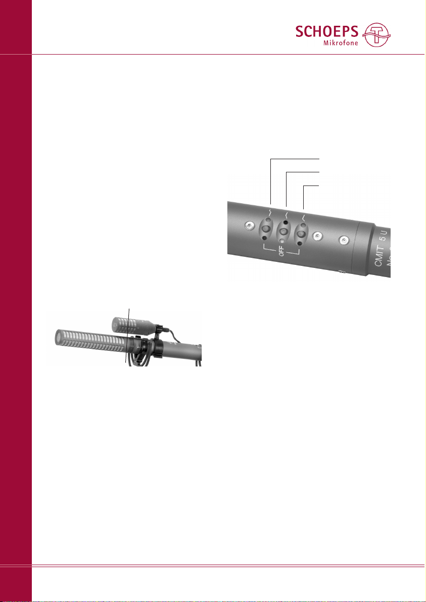
des Hallradius' sinnvoll. Im Freien ist dieser
sehr groß und daher unkritisch oder gar nicht
vorhanden (keine Reflektionen). In Räumen
sollte sich das Mikrofon nah an der Schall quelle befinden.
5. Für stereofone Aufnahmen sind Rohr-Richt mikrofone nur bedingt zu empfehlen, weil ihr
Richtdiagramm bei hohen Frequenzen anders
ist als bei tiefen. Daher können XY-Aufnah men
nicht empfohlen werden. MS-Aufnahmen mit
dem CMIT 5 U und einem kleinen aufgeklipsten
Acht-Mikrofon (CCM 8 KOMPAKTMIKROFON oder
Mikrofonkapsel MK 8) hingegen können sehr
gut sein.
Bei der Montage eines Mikrofons (CCM 8)
bzw. Kapsel mit Achtcharakteristik (MK 8) auf
einem Rohr-Richtmikrofon sollte man sich vergewissern, dass ihre Membranen direkt übereinander angeordnet werden. Dabei ist zu
berücksichtigen, dass die Membran eines RohrRichtmikrofons am Anfang des Interferenz rohrs liegt, nicht an dessen vorderen Ende:
Filter
Das CMIT 5 U verfügt über drei zuschaltbare
Filter. Sie werden jeweils durch Antippen eines
Tasters ein- bzw. aus geschaltet. Mit ihnen können die Tiefen abgesenkt, bzw. die Höhen
angehoben werden.
Die beiden Tiefenfilter setzen bei 80 Hz
bzw. 300 Hz ein. Aber auch wenn beide ausgeschal tet sind, ist ein weiteres ab 40Hz aktiv
mit einer Steil heit von 6 dB/Okt. Das steilflankige Filter ab 80Hz (18dB/Okt.) ist zum Schutz
vor nieder frequenten Wind geräuschen und
Körper schall vorgesehen. Das Filter ab 300Hz
(6dB/Okt.) setzt weich ein und dient der Kom pen sa tion des Nah bespre chungs effekts (Anhe bung der Tiefen bei Besprechung von richtenden Mikrofonen aus geringem Abstand). Die
Tiefenfilter dienen auch als Schutz vor stören dem, unhör barem (Infra-) Schall, der durch
Lüftungs an la gen, Schienen fahrzeuge oder Wind
entstehen kann. Das Tückische ist: Obgleich er
selbst nicht wahrgenommen wird, kann Infra schall durch die Übersteuerung z.B. des Ein gangs des angeschlossenen Geräts starke, hörbare Verzer run gen ver ursa chen. Damit wäre
eine brauchbare Aufnahme nicht möglich.
Mittels der Höhenanhebung lässt sich die
Höhenabsorption von Windschutzen kompen sieren und die Sprach verständlichkeit verbessern.
LEDs neben jedem Taster zeigen den Betriebs zustand der Filter an. Grün bedeutet ”Filter
aus”, also konstanter Frequenzgang. Rot bedeutet: ”Achtung, das Filter ist eingeschaltet.”
SCHOEPS GmbH · Spitalstr. 20 · D-76227 Karlsruhe (Durlach) · Tel: +49 721 943 20-0 · Fax: +49 721 943 2050
www.schoeps.de · [email protected]
Filter
5
Deutsch
80Hz, 18dB/Okt.
300Hz, 6dB/Okt.
+5dB bei 10kHz
MS mit Rohr-Richtmikrofon (hier: CMIT 5 U mit
CCM 8 und Klammer KMSC).
Die Membranen der beiden Mikrofone müssen
exakt übereinander liegen. Die Linie im Bild
oben zeigt ihre Position.
*Hallradius: Wenn man eine Schallquelle in einem
Raum betrachtet, hat man sowohl einen Pegel des
Direktschalls, der mit dem Abstand zur Schallquelle
stark abnimmt als auch einen Pegel des Diffusschalls,
der sich durch (wiederholte) Reflektionen des Direkt schalls an akustischen Hinder nis sen (vor allem den
Wänden den Raums) ergibt. Der Diffus schallpegel ist
weniger stark vom Abstand der Schallquelle abhän gig
als der Direkt schall, im Grenzfall sogar völlig unabhängig (idealer Hallraum). Der Abstand, wo der direkte
und der reflektierte Schall gleichen Pegel haben, wird
Hallradius genannt. Man spricht von einem Radius,
da man von einer Punkt schallquelle mit kreisförmiger
Schallausbreitung aus geht.
Page 6
SCHOEPS GmbH · Spitalstr. 20 · D-76227 Karlsruhe (Durlach) · Tel: +49 721 943 20-0 · Fax: +49 721 943 2050
www.schoeps.de · [email protected]
Inbetriebnahme
6
Deutsch
Inbetriebnahme / Phantomspeisung
Das CMIT 5 U besteht im Wesentlichen aus
zwei Kom ponenten – dem akustischen Wand ler
(der “Kapsel”) und dem Mikro fon ver stär ker.
Die Kondensatorkapsel wandelt Schallwellen
in eine ent sprechende elektrische Spannung.
Sie bestimmt nicht nur die Richtcharakteristik,
son dern prägt fast ausschließlich die klanglichen Eigenschaften des Mikrofons. Der Ver stär ker des CMIT 5 U verfügt über eine Schaltung
zum Laden (Pola ri sie ren) der Kondensator kap sel. Durch ihn wird ihr Sig nal praktisch nicht
beeinflusst, denn er verstärkt es nur, macht es
niederohmig (so dass es durch ein Kabel über tragen werden kann). Der Ausgang ist elek trisch
symme trisch aufgebaut, damit elektro mag ne tische Einstreuun gen in das Kabel nicht stören
können. Z.B. das so genannte “Netzbrummen”
wird hierdurch verhindert. Filter verhindern
das Eindringen von Hochfrequenz (z.B. von
Handys), die ins Kabel eingestreut wurde.
Der Mikrofonverstärker des CMIT 5 U arbei tet
mit einer über tra ger- und kon den sa tor freien
Aus gangs stufe im AB-Betrieb. Das führt zu der
niedrigen Aus gangs impe danz, geringen Ver zer run gen und kleinen Abmes sungen.
Inbetriebnahme
Das CMIT 5 U ist elektrisch aktiv und muss deshalb mit Strom versorgt werden. Dies überneh men meist die Mikrofoneingänge des Misch pults, Mikrofon-Vorverstärkers (z.B. SCHOEPS
VMS 5 U) oder Rekor ders, wenn eine entprechende Spei sung eingebaut ist.
Wie die meisten professionellen Konden sa tormikrofone erfordert auch das CMIT 5 U den
Betrieb an einer genorm ten, so genannten 48VPhantom speisung wie sie von den Aufnahme geräten üblicherweise zur Verfügung gestellt
wird.
Das CMIT 5 U wurde mit einer norm gerechten Spei sun g entwickelt und getestet. Wir
kön nen das ein wandfreie Funk tionieren mit
abweichen den Speisungen nicht garantieren.
Diese kön nen – besonders bei hohen Schall druckpegeln oder starken Wind geräuschen –
Be triebs pro bleme ver ur sa chen (Verzerrungen
und sogar Signal unter brechun gen), deren Grund
oft un er kannt bleibt.
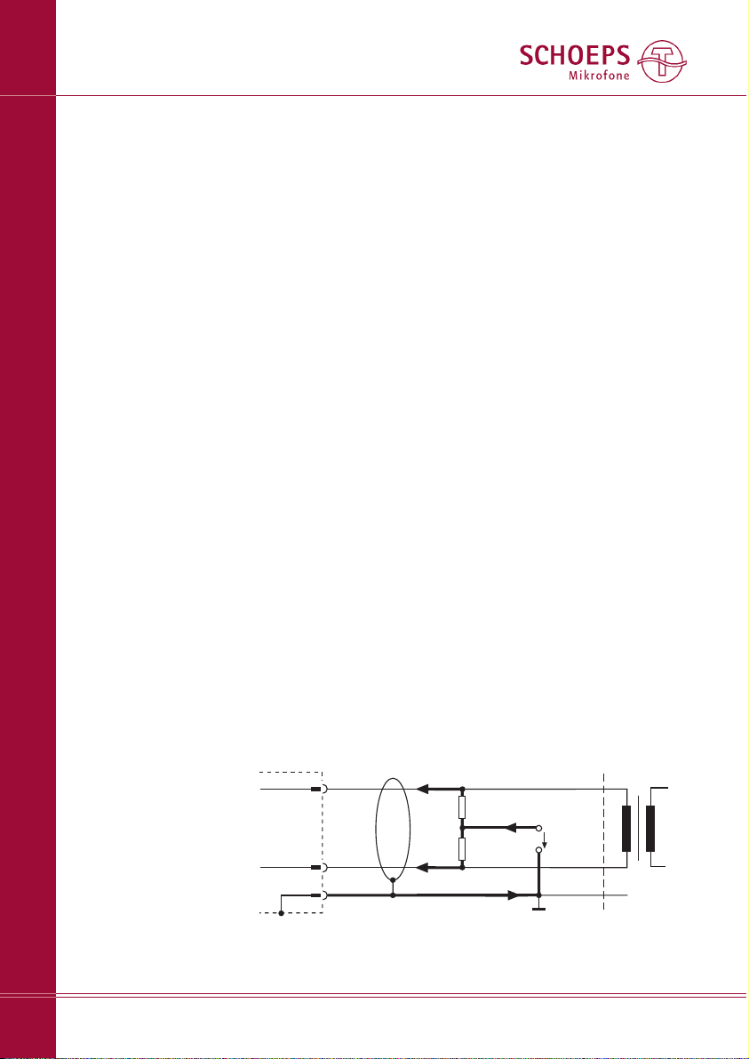
+ Phase
- Phase
2 (4)
3 (5)
Mikrofon
1
Schirm
Kabel
Speisung
R
S
U
S
Eingang
R
S
P48: US= 48 V ± 4 V; RS= 6,8 kW*, I
max.
= 10 mA
P12: U
S
= 12V ± 1V; RS= 680 W*, I
max.
= 15 mA
I/2
I/2
I
Abbildung 1
Eingang mit Übertrager
(oder symmetrischer, erdfreier, eisenloser Eingang)
XLR-3Stecker
* Toleranz: ±20%, aber: Paarungstoleranz: ±27 Ohm
Der zuletzt gewählte Zustand der Filter (ein / aus)
wird gespeichert und ist beim Ein schalten wieder aktiv.
Durch die LEDs neben den Tastern ist auch
bei schlechten Licht verhältnissen und selbst im
Dunkeln erkennbar, ob das Mikrofon in Betrieb
ist und welche Filter aktiv sind.
Page 7

SCHOEPS GmbH · Spitalstr. 20 · D-76227 Karlsruhe (Durlach) · Tel: +49 721 943 20-0 · Fax: +49 721 943 2050
www.schoeps.de · [email protected]
Phantomspeisung
7
Deutsch
Phan tom spei sung nach DIN EN 61938
(früher DIN 45 596)
Die ”Phantom-”Speisung ist die Standard spei sung für Kondensatormikrofone. Sie arbeitet
mit einem zweiadrigen, geschirmten Kabel. Auf
beiden Adern liegt die gleiche Span nung und
es fließen exakt gleiche Ströme in ihnen.
Abb. 1 zeigt die ein zig gültige 48V-Phan tom spei sung (kurz P48). Sie wird mit ohm schen
Wider ständen re a li siert. Diese Abbildung entspricht der Norm EN 61938 von 1997.
Die zulässige To le ranz des Wertes der Spei sewider stände ist ± 20%. Hingegen darf die
Differenz zwischen ihnen nicht größer als
0,4% sein (das sind 27 Ohm). Nur so ist eine
ausreichende Impedanz-Symmetrie gegeben.
Ansonsten könnte es zu einem Differenzstrom
kommen, der bei einem Eingangsübertrager
zu einer ver ringerten Aus steuer bar keit bzw.
Ver zerrun gen führen würde.
Der ma xi ma le Strom, den ein Mikrofon
nach Norm an einer 48V Phan tomspeisung
aufnehmen darf, beträgt 10mA. Das SCHOEPS
CMIT 5 U benötigt 4,4mA. Damit liegt es weit
unter dieser Grenze.
Obwohl die Phantomspeisung nicht aufwändig oder kompliziert ist, gibt es leider vor allem
bei älteren, aber verein zelt auch bei neuen
Vor verstär kern und Misch pul ten Spei sun gen,
die nicht der Norm entsprechen und dadurch
nicht aus rei chend Strom zur Ver fü gung stellen
können. Im Zweifels fall sollte deshalb über prüft werden, ob bei dem vor lie gen den Gerät
das profes sio nelle Arbei ten über haupt mög lich
ist. Auf Seite 12 wird beschrie ben, wie Sie
eine Prü fung einfach und schnell durch führen
können.
Unsymmetrischer Betrieb
Manchmal stellt sich das Problem, dass sich
kein symmetrischer Eingang mit Phantom spei sung, sondern nur ein unsymmetrischer Ein gang, meist noch ohne Speisung zum Betrieb
des Mikrofons findet. Die Versuchung ist groß,
doch raten wir vom unsymmetrischen Betrieb
des CMIT 5 U ab, da es hierfür nicht vorgesehen ist, und der Vorteil der Phantomspeisung
(die Störsicherheit) hiermit verloren geht. Stattdes sen sollte ein hochwer ti ger Eingangsüber tra ger ver wen det wer den, um aus dem un sym me tri schen einen sym me tri schen Eingang
zu ma chen. So bleibt das Sig nal auf dem Kabel
symmetrisch und die gute Stör un terdrückung
erhalten.
Nimmt man den Nachteil der Unsymmetrie
in Kauf, so kann der unsymmetrische Betrieb
realisiert werden, indem man das Signal an
Pin 2 über einen Kon densator auskoppelt
(Wert: 100μF, 63V bei R= 22kΩ). An Pin 3
liegt kein Signal an. Die Speisung des Mikro fons über alle drei Pins muss natürlich gewähr leistet bleiben. Beim CMIT 5 U bleibt der Stör span nungs ab stand bei dieser Betriebsart un ver än dert.
Gleichzeitiger Betrieb an mehreren Geräten
Soll ein Mikrofon gleichzeitig an mehreren
Geräten betrieben werden, empfehlen wir die
Verwendung eines aktiven Mikrofonsplitters um
die Spezifikationen bzgl. der Last und der Spei sung des Mikrofons einzuhalten und einen
einwandfreien Betrieb zu gewährleisten.
Ma xi ma le Ka bel län ge
Im üblichen Einsatzgebiet eines Rohr-Richt mikro fons, nämlich an der Angel, werden Kabel
mit nur einigen Metern Länge eingesetzt. Am
CMIT 5 U können Kabel bis zu einer Länge von
ca. 300m angeschlossen werden. Die maxi male Länge hängt vor allem von der oft nicht
be kann ten elek tri schen Ka pa zi tät des Ka bels
ab. Je kleiner diese pro Me ter ist, de sto länger
darf das Kabel sein. SCHOEPS-Kabel sind besonders kapazitäts arm (100 pF/m zwischen den
Leitern).
Extrem lange Kabel haben einen Einfluss vor
allem auf die Höhen: Der Pegel sinkt auf Grund
der elektrischen Kapa zi tät des Kabels gering fügig. Die Aussteuer bar keit geht zurück, was
sich aber nur bei sehr hohen Schall druck pegeln
bemerk bar macht. Außer dem können ver stärkt
Stö run gen in das Kabel gelangen.
Page 8

Hin wei se zur Vermeidung von Stör ein streuungen
Das CMIT 5 U ist un empfindlich gegenüber
magnetischen, elektri schen und elektromag ne tischen Feldern. Auf Grund ihres großen
Dyna mik um fangs reichen die kleinsten Signal ampli tuden bei Stu dio mikro fonen jedoch bis
in den Mikro volt-Bereich (1 µV= 1/1.000.000
Volt!). Ferner sind nicht nur die Eigenschaften
des Mikrofons selbst von Bedeutung, sondern
auch die Schirmung des Kabels und die
Masse füh rung des angeschlossenen Eingangs.
Daher kann nicht erwar tet werden, dass
Mikro fone unter allen Umstän den völlig frei
von Stö run gen sind. Folgende Regeln können
jedoch helfen, Störun gen zu vermeiden oder
deutlich zu reduzieren:
– Meiden Sie die Nähe sowohl des Mikro fons
als auch seines Anschlusskabels zu Stör quel len wie Moni toren, digitalem Equip ment
(Rechnern), Sendern (z.B. Handys), Trans for ma toren, Stark strom kabeln, Dimmern,
Schalt netzteilen etc.
– Verwenden Sie hochwertige Kabel (hoher
Bedeckungsgrad der Schirmung, z.B. SCHOEPS
K EMC 5 U) und halten Sie diese so kurz
wie möglich.
– Verlegen Sie Mikrofonkabel nie parallel zu
Netzkabeln und kreuzen Sie diese, wenn das
unumgänglich ist, stets senkrecht.
– Achten Sie darauf, dass der Kabelschirm am
Mikrofoneingang auf kürzestem Wege mit
dem Gehäuse verbunden ist – wenn möglich galvanisch, sonst kapazitiv.
SCHOEPS GmbH · Spitalstr. 20 · D-76227 Karlsruhe (Durlach) · Tel: +49 721 943 20-0 · Fax: +49 721 943 2050
www.schoeps.de · [email protected]
Vermeidung von Störeinstreuungen/ Wind, Vibrationen...
8
Deutsch
Wind, Vibrationen und Übersteuerungen
Windgeräusche und Windschutze
Störgeräuschen, die durch Luftströmungen
ver ursacht werden (Wind, Poppen bei gesunge nen oder gesprochenen Konsonanten, Bewe gungen des Mikrofons an der Angel oder Luft strömungen durch Heizungs- oder Lüf tungs systeme), sollte, auch wenn sie nicht zur Über steuerung führen, in jedem Fall entgegen
gewirkt werden, da sie den Klang beeinträchtigen. Ein Wind- oder Poppschutz sollte ver wen det werden. Diesen gilt es, mit Bedacht
zu wählen, um die Eigenschaften des Mikro fons
nicht unnötig stark zu beeinträchtigen, denn
Wind schutze haben allgemein die Nei gung,
nicht nur den Wind geräuschpegel herab zu
setzen, sondern auch die Richtwirkung und /
oder die Höhen wiedergabe. Windschutzkörbe
führen vor allem zu einer Welligkeit des Fre quenz gangs, während Schaumstoff wind schutze
vorwiegend eine Höhenabsenkung bewirken.
Schwingungen / Vibrationen
Wenn Störungen in Form von mechanischen
Vibrationen über das Stativ oder die Angel das
Mikrofon erreichen können (Greifgeräusche),
sollte eine elastische Auf hängung verwendet
werden. Dabei sollte das Kabel am Mikrofon
in einer Schleife verlegt und angebunden oder
angeklemmt werden, so dass es nicht zu einem
Nebenweg für Stö run gen wird und auch nicht
durch sein Gewicht am Mikrofon zieht. In vielen Situationen ist es ratsam, sie vorsichtshalber einzusetzen.
Übersteuerungen
Wenn man es mit Übersteuerungen zu tun hat,
sollte man sich die gesamte Aufnahme kette als
eine Reihe von Schaltungs stufen vorstellen.
Dann geht es darum herauszufinden, welches
die erste übersteuerte Stufe ist, und das Signal
genau an deren Eingang zu dämpfen (im Pegel
zu reduzieren). Würde die Dämp fung an einer
davor liegenden Stufe vorgenommen, würde
unnötig Rauschen hinzukommen, während
gleiches bei einer späteren Stufe das Problem
nicht lösen würde.
In diesem Sinne besteht ein Kondensator -
Page 9
SCHOEPS GmbH · Spitalstr. 20 · D-76227 Karlsruhe (Durlach) · Tel: +49 721 943 20-0 · Fax: +49 721 943 2050
www.schoeps.de · [email protected]
Wind, Vibrationen und Übersteuerungen
9
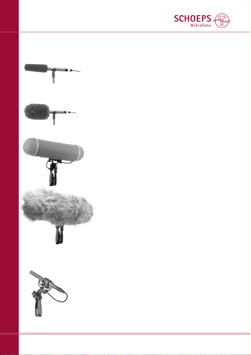
Schaumstoffwindschutz W 140
(im Lieferumfang des CMIT 5 U)
Fell-Windschutz “Softie”, Ø 12cm
Windschutzkorb WSR CMIT U mit Connbox;
unten: mit Windjammer WJ CMIT (dieser ist
separat zu bestellen)
Windschutze für das CMIT 5 U:
Rycote “Softie Lyre
Mount” (inklusive
40cm langes XLR-3Kabel);
erhältlich ab 06/09
mi krofon aus zwei Schaltungsstufen – dem
Schall wandler (Kap sel) und dem Verstärker.
Eine Kap sel wird praktisch kaum je übersteuert, außer durch Explosionen oder wenn sie
ungeschützt sehr starkem Wind ausgesetzt
wird. Der Schall druck pegel, bei dem eine
SCHOEPS-Mikro fon kapsel über steuert, ist
extrem hoch – ca. 150dB. Die Kapsel wird
hierbei in der Regel nicht zerstört. Auch das
Anblasen mit dem Mund oder mit Druckluft
übersteht sie schadlos. Ein korrekt gespeistes
CMIT 5 U kann mehr als 130dB SPL verarbeiten. Solche Pegel treten bei natürlichen Schall quellen kaum auf. Wind in Verbindung mit
Druck gradien ten-Emp fängern kann jedoch zu
vergleichbaren Signalamplituden führen. Auch
sollte eine korrekte Speisung nicht als
Selbstverständ lich keit betrachtet werden. Nicht
ausreichende oder inkorrekte Mikrofon spei sungen stellen erfahrungsgemäß die Ursache vieler
mysteriöser ”Übersteuerungsprobleme” dar.
Wenn Wind und Speisungsprobleme als
Ursache ausgeschlossen werden können, treten Übersteuerungen häufiger im Mischpult
oder der Eingangsstufe des Vorverstärkers als
beim Mikrofon selbst auf. Das gilt besonders
für Consumer-Audiogeräte, aber es gibt auch
heute immer noch professionelles Equip ment,
das primär für den Einsatz mit dynamischen
oder Kondensatormikrofo nen mit geringer
Empfindlichkeit konzipiert ist. Wenn die Vor verstärkung eingestellt werden kann, sollte sie
so niedrig gewählt werden, dass keine Übersteuerung des Eingangs erfolgt, aber nicht so
niedrig, dass Rauschen hinzu gefügt wird,
wenngleich ein paar dB zusätzlichen Rauschens
dem Risiko einer harten Übersteuerung vorzuziehen sind. Leider kann man sich jedoch selbst
bei professionellen Geräten nicht immer darauf
verlassen, dass die Übersteuerungsanzeige
auch die Übersteue rung des Eingangs anzeigt,
denn oft ist die Schaltung für die Übersteuerungsanzeige nur mit einer der nach fol gen den
Stufen verbunden.
Wenn Übersteuerungen auftreten, obwohl
weder die Speisung, noch hohe Schalldruck pegel oder Wind die Ursache sind, und die
Vorverstärkung nicht eingestellt werden kann,
sollte ein symmetrisches Dämpfungsglied
Deutsch
Page 10

(Widerstands-Netz werk, SCHOEPS MDZ 10
oder MDZ 20) vor den Eingang des Vorver stär kers geschaltet werden. Wenn dies die Klang quali tät verbessert, sollten Sie es dort belassen.
Es ist stets besser, den Eingang des Vorver stärkers zu dämpfen als Dämpfungsschalter im
Mikrofon einzusetzen. Deshalb wurde beim
CMIT 5 U darauf verzichtet.
Mitunter sind tieffrequente Störungen wie
Wind und Körperschall nicht direkt als solche
wahrnehmbar. Dennoch kann Infraschall an
einer der Stufen der Signalkette zur Über steuerung führen. Der Einsatz eines Windschutzes
ist die erste und beste Gegenmaßnahme, aber
niederfrequente Störungen können auch mittels der Aktiven Filter LC 60 oder LC 120 am
Ein gang von Vor ver stärkern mit Phantom spei sung eingesetzt werden.
Wie schon erwähnt sind Übersteuerungen,
für die es sonst keine Erklärung gibt, oft ein
Anzeichen für eine fehlerhafte oder falsch
gewählte Mikro fon spei sung. Die Speisung wird
am Beginn dieser Bedienungsanleitung auf
Seite 6 besprochen.
Die geeignetsten und hilfreichsten Werk zeuge
zur Fehlersuche sind:
– ein bekanntermaßen einwandfreies Mikro -
fonkabel,
– ein einfacher Windschutz wie der SCHOEPS
W 140 oder – für Außenaufnahmen – ein
Wind schutzkorb wie der WSR CMIT U,
– ein symmetrisches Dämpfungsglied (”Pad”)
wie der SCHOEPS MDZ 10 oder MDZ 20,
– ein gewöhnliches Multimeter oder der Phan-
tomspeisungs-Tester PHS 48 von SCHOEPS.
SCHOEPS GmbH · Spitalstr. 20 · D-76227 Karlsruhe (Durlach) · Tel: +49 721 943 20-0 · Fax: +49 721 943 2050
www.schoeps.de · [email protected]
Pflege und Wartung
10
Deutsch
Pfle ge und War tung
Sor gen Sie bit te stets da für, dass das Mikro fon
nicht in stau bi ger Um ge bung ein ge setzt wir d
und dass es nach Ge brauch in ei nem ge schlosse nen Be hält nis (z.B. in dem mitgelie fer ten
Holzetui) auf be wahrt wir d, denn das Ein drin gen
von Staub kann seine Funk tion be ein träch ti gen.
In Ver bin dung mit einer ho hen Luft feuch tig keit kann er zur Kon den sa tion und da mit zu
Knack ge räu schen führen.
Was tun, wenn das Mi kro fon bei er höh ter Feuch tig keit knackt oder rauscht?
Wenn Sie das Mi kro fon z.B. an ei nem Win ter tag von drau ßen in kal tem Zu stand in einen
war men Raum brin gen, kann es zur Kon den sa tion von Feuch tig keit und da mit zu Knack oder Prasselge räu schen etc. kom men. Ge ben
Sie dem Mi kro fon in die sem Fall ca. ei ne halbe
bis eine Stun de Zeit zum Auf wär men, dann wird
es in der Re gel wie der ein wand frei ar bei ten.
Soll te das Knacken nach die ser Maß nah me
nicht be sei tigt sein, ist wahr schein lich Staub in
das Innere des Mikrofons gelangt. Dann soll ten
Sie es zur Rei ni gung ins Werk ein schicken. Von
ei ner selbst durchgeführten Öff nung und Rei ni gung ra ten wir drin gend ab, un ter an de rem
des halb, weil hier durch je der Garan tie an spruch
er lischt.
Ist der Einsatz in schmutziger oder staubiger
Umgebung unvermeidlich, sollte ein Wind schutz
verwendet werden, um die oben beschriebenen Probleme zu vermeiden.
Aktive InLine-Tiefen filter LC 60
bzw. LC 120
Phantomspeisungs tester PHS 48
Dämpfungs glied
MDZ 10
Page 11
SCHOEPS GmbH · Spitalstr. 20 · D-76227 Karlsruhe (Durlach) · Tel: +49 721 943 20-0 · Fax: +49 721 943 2050
www.schoeps.de · [email protected]
Technische Daten
11
Deutsch
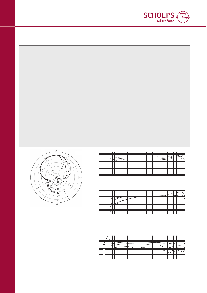
Richtcharakteristik: . . . . . . . . . . . Superniere / Keule
Übertragungsbereich: . . . . . . . . 40Hz – 20kHz
Zuschaltbare Filter: . . . . . . . . . . . 80Hz mit 18dB/Okt.,
300Hz mit 6dB/Okt.,
5dB Anhebung bei 10kHz (Shelving)
Empfindlichkeit: . . . . . . . . . . . . . 17mV/Pa
Ersatzgeräuschpegel (Filter aus): . 14dB-A*, 24dB CCIR**
Grenzschalldruckpegel: . . . . . . . 132dB SPL bei 0,5% THD
Polarität: . . . . . . . . . . . . . . . . . . Ein Druckanstieg auf der 0°-Achse des CMIT 5 U führt zu
einem Anstieg der Spannung an Pin 2.
Stromversorgung: . . . . . . . . . . . 48V Phantomspeisung
Stromaufnahme: . . . . . . . . . . . . 4,4mA
Maximale Ausgangsspannung: . 1,3V (bei 1kHz, 1kOhm)
Ausgangsimpedanz: . . . . . . . . . 50 Ohm
Mindest-Lastimpedanz: . . . . . . . 600 Ohm
Länge: . . . . . . . . . . . . . . . . . . . . 251mm
Durchmesser: . . . . . . . . . . . . . . . 21mm
Gewicht: . . . . . . . . . . . . . . . . . . nur 89g
Oberfläche: . . . . . . . . . . . . . . . . eloxiert
Technische Daten:
von außen
nach innen:
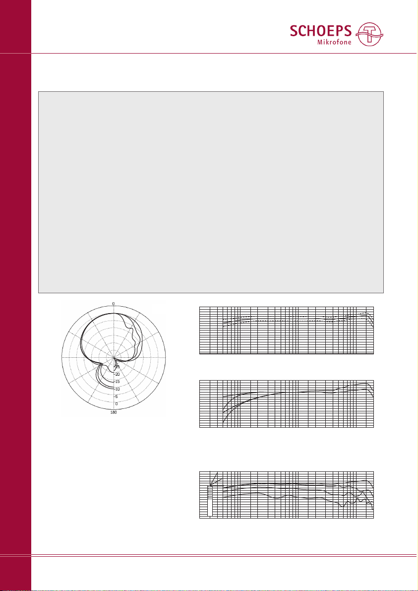
250Hz 4kHz
500Hz 8kHz
1kHz 16kHz
2kHz
* nach IEC 61672-1
** nach IEC 60268-1
Polardiagramm
Frequenzgang ohne Filter bei 30°, 60°, 90° Einfallswinkel
Frequenzgang mit Toleranzfeld
Frequenzgang:
1) ohne Filter 2) 80Hz, 18dB/Okt.
3) 300Hz, 6dB/Okt. 4) 80Hz + 300Hz 5) 10kHz: +5dB
20 50 100 200 500 1k 2k 5k 10k 20kHz
+10
-10
0dB
-20
20 50 100 200 500 1k 2k 5k 10k 20kHz
+10
-10
0dB
-20
20 50 100 200 500 1k 2k 5k 10k 20kHz
+10
-10
0dB
-20
30°
60°
90°
1
2
3
4
5
1
Page 12
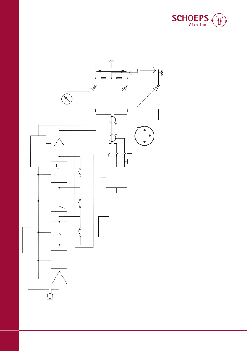
DC generator
regulator
micro controller, LEDs
preamp
impedance
converter
filter 1
push-
buttons
filter 2 filter 3
output
stage
RFI
filter
SCHOEPS GmbH · Spitalstr. 20 · D-76227 Karlsruhe (Durlach) · Tel: +49 721 943 20-0 · Fax: +49 721 943 2050
www.schoeps.de · [email protected]
Blockschaltbild des CMIT 5 U
12
Deutsch
[1] +Phase: Eine Auslenkung der Membrane zur Gegenelektrode (positive
Druckphase) führt zu einem positiven Signal an diesem Stift.
[2]Gepaart (d.h. mit nur 0,7% Paarungstoleranz), siehe Seite 6.
[3] Hier finden Sie drei Methoden zur Überprüfung der Phantomspeisung.
Diese Messun gen sollten an einem nicht verwendeten Eingang gemacht
werden. Stellen Sie die Verstärkung (Gain) dieses gewählten Kanals auf
das Mini mum ein um Lautsprecher etc. zu schützen. Wenn gleichzeitig
Mikro fone an andere Eingänge angeschlossen sind, sollte dies die
Ergeb nisse nicht wesentlich beeinflussen.
1) Messen Sie die Leerlaufspannung zwischen Masse (Pin 1) und Pin 2
oder Pin 3 der XLR-Eingangsbuchse. Unter Berücksichtigung der erlaub-
ten Toleranz sollte hier bei P48 eine Gleichspannung zwischen 44 und
52V anliegen.
Messen Sie nun den Kurzschluss-Strom zwischen Masse (Pin 1) und Pin 2
oder Pin 3 des XLR-Eingangs. Unter Berücksichtigung der erlaubten
Toleranz sollte der Gleichstrom bei P48 zwischen 5,9 and 8,5 mA lie-
gen. Beachten Sie: Dies darf der Schaltug nicht schaden, schließlich
würde das Anschließen eines unsymmetrischen Gerätes, wie es manch-
mal notwendig ist, zu dem gleichen Strom führen. Sicherheitshalber
jedoch sollte der Kurzschluss nicht länger anhalten als nötig.
2) Messen Sie die an den Signal führenden Adern (Pins 2 und 3) an lie -
gen den Span nun gen während des Be triebs ei nes Mi kro fons (z.B. am
ge öff ne ten Stecker). Diese beiden Span nungen müssen gleich sein und
sollten bei 33V, mindestens aber 29 Volt liegen.
3) Bei P48 können Sie den SCHOEPS-Teststecker PHS 48 verwenden. Leuch-
tet die LED nach dem Einstecken permanent, ist die Speisung in Ordnung.
3
1
2
Phantom-
speisung [3]
U
s
= +48V
R
s
[2]= 6,8 kΩ
R
s
[2]= 6,8 kΩ
Vorver -
stärker,
Recor der
oder
Misch -
pult
∼
∼
Schirm
-Phase
+Phase
XLR-3-
Stecker
XLR-3-
Stecker
Pin 1: Schirm (GND)
Pin 2: +Phase[1]
Pin 3: –Phase
Ansicht von unten (Stiftseite)
1
2
3
Mikrofon -
kabel
[3]
Page 13

Garantie
Wir übernehmen für unsere Produkte eine
Garantie von 24 Monaten.
Zum Nachweis der Garantie heben Sie bitte
unbedingt den Kaufbeleg auf. Ohne ihn wer den Repa ra turen grundsätzlich kostenpflichtig
ausgeführt.
Die Garantieleistungen bestehen nach
unse rer Wahl in der unentgeltlichen Beseiti gung von Material- oder Herstellungsfehlern
durch Reparatur, Tausch von Teilen oder des
kom plet ten Gerätes.
Von der Garantie ausgenommen sind Män gel
durch unsachgemäßen Gebrauch (z.B. Bedie nungsfehler, mechanische Beschä di gun gen),
Verschleiß oder höhere Gewalt. Der Garan tie anspruch verfällt bei Eingriffen durch nicht
autorisierte Personen oder Werk stätten.
Im Garantiefall senden Sie das Produkt
zusammen mit dem Kauf beleg frei Haus an
SCHOEPS, wenn Sie in Deutschland wohnen,
bzw. an unsere Vertretung, wenn Sie außerhalb Deutschlands wohnen. In Ausnahme fäl len können Sie es nach vorheriger Rücksprache
mit SCHOEPS auch aus dem Ausland direkt an
uns senden.
Gewährleistungsansprüche aus dem Kauf ver trag gegen den Verkäufer werden durch
diese Garantie nicht berührt.
Die Garantie kann uneingeschränkt in allen
Ländern in Anspruch genommen werden.
CE-Konformitätserklärung
Das CE-Kennzeichen besagt, dass die so
gekenn zeichneten Produkte allen relevanten
Normen der Europäischen Gemeinschaft entsprechen. Die in dieser Bedienungsanleitung
beschriebenen Produkte genügen diesen
Normen, wenn sie mit Kabeln von SCHOEPS
betrieben werden.
Geltende Richtlinien:
EMV-Richtlinie: 89/336/EEC, ergänzt um
92/31/EEC und 93/68/EEC
Geltende Normen:
EN 55 103-1, -2 und jene, auf die darin Bezug
genommen wird.
SCHOEPS GmbH · Spitalstr. 20 · D-76227 Karlsruhe (Durlach) · Tel: +49 721 943 20-0 · Fax: +49 721 943 2050
www.schoeps.de · [email protected]
Garantie, CE-Konformitätserklärung
13
Deutsch
Page 14
CMIT 5 U
Interference Tube “Shotgun” Microphone
User Guide
Table of Contents
page
Features / accessories 15
Applications 17
Filters 18
Starting up 19
Phantom powering 20
Hints on avoiding interference 21
Troubleshooting 22
Care and maintenance 24
Technical specifications 25
Block diagram 26
Warranty 27
14
Page 15
SCHOEPS GmbH · Spitalstr. 20 · D-76227 Karlsruhe (Durlach) · Tel: +49 721 943 20-0 · Fax: +49 721 943 2050
www.schoeps.de · [email protected]
Features / Accessories
15
English
English
Dear Customer:
Congratulations on the purchase of your
SCHOEPS CMIT 5 U shotgun microphone.
To get the most out of your microphone,
there are a few basic principles you should
consider. This guide covers these principles,
followed by some notes on wind and overload, as well as caring for your microphone.
Technical data is provided in the appendix.
Unique Features of the CMIT 5 U
The CMIT 5 U is a classic condenser microphone (pressure gradient microphone) with an
acoustic interference tube arranged in front of
it. In the midrange and high-frequency range,
this results in greater off-axis rejection than
with supercardioids, the most strongly directional “short” microphones. The result is a
lobe-shaped polar pattern.
The CMIT 5 U stands out for:
– its interference tube, which takes effect at a
relatively low frequency without the pickup
pattern becoming too narrow at high fre-
quencies,
– its excellent sound quality (making it a great
all-purpose microphone, even for use as a
spot microphone at music recordings, for
example),
– its very light weight,
– its great immunity to wind noise,
– a directional pattern which remains the same
in both the vertical and horizontal plane,
– three pushbutton-activated filters,
– a balanced, low-impedance transformerless
output, which allows interference-free oper-
ation even with very long cables
– superior RF rejection
Rycote
12 cm “Softie”
Rycote “Softie Lyre
Mount”; available as
of June 2009
WJ CMIT fur-like “overcoat” (“Windjammer”)
for WSR CMIT U
Connbox
Optional accessories:
For Mono:
WSR CMIT LU basket-type windscreen
(100 mm diameter; comprises: elastic suspension, pistol grip, cable and Connbox
WJ CMIT Windjammer for WSR CMIT LU
Available only at your Rycote dealer:
WSR CMIT U
W 140
SG 20
Polished wood case
Included accessories:
Page 16
SCHOEPS GmbH · Spitalstr. 20 · D-76227 Karlsruhe (Durlach) · Tel: +49 721 943 20-0 · Fax: +49 721 943 2050
www.schoeps.de · [email protected]
Accessories
16
English
WSR MS CMIT U with WJ CMIT Windjammer
Connbox
For M/S stereo:
WSR MS CMIT LU basket-type windscreen
(100 mm diameter; comprises: elastic suspension, pistol grip, cable and Connbox),
KMSC double clip (see page 18),
WJ CMIT Windjammer (must be ordered sepa-
rately)
Further a microphone with a figure-8 directional pattern is needed – the CCM 8Lg.
Connbox
WSR MS CMIT LU
basket-type windscreen
WSR DMS CMIT LU
basket-type windscreen
For Surround using the Double M/S recording technique:
WSR DMS CMIT LU basket-type windscreen
(150 mm diameter; comprises: elastic suspension with pisto l grip and Connbox),
2 × KMSC double clip,
WJ DMS CMIT Windjammer (must be ordered
separately)
Further the following microphones are required:
1× CCM 4Lg ”cardioid”,
1× CCM 8Lg ”figure-8”.
WSR DMS CMIT LU with WJ DMS/ORTF
Windjammer
Page 17
SCHOEPS GmbH · Spitalstr. 20 · D-76227 Karlsruhe (Durlach) · Tel: +49 721 943 20-0 · Fax: +49 721 943 2050
www.schoeps.de · [email protected]
Applications
17
English
Applications
The CMIT 5 U is the ideal microphone for reporting, interviewing or dialogue for film and TV.
It is one of the very few shotgun microphones
in existence that can also be used as a spot
microphone for music recording, thanks to its
balanced frequency response and frequencyindependent polar pattern (with comparably
little difference between low and high frequencies).
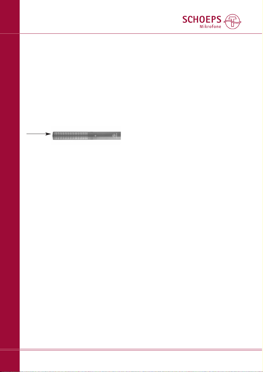
Sound is picked up along its axis:
Always make sure all of the slits in the tube
(sound inlet openings) are free and uncovered
when using the microphone. This is especially
important when using M/S or double-M/S techniques requiring clips for mounting additional
microphones onto the CMIT 5 U. Covering
slits can alter the sound and directivity of the
microphone.
Here are some things which are worth knowing
about ”shotgun” microphones, including the
SCHOEPS CMIT 5 U:
1. For any given length of the interference
tube, a shot gun microphone's design can be
optimized for maximum directivity or for best
sound quality, but unfortunately not for both
at the same time. The SCHOEPS CMIT 5 U has
been optimized for best sound quality.
2.1 Room reflections and reverberance contribute enormously to the character of any
sound. With a shotgun microphone, the pickup angle at high frequencies will be narrower
than at lower frequencies; as a result, diffuse
room sound will be picked up with a distinct
high-frequency rolloff, which can make the
sound rather dull. This tendency will be emphasized further if a windscreen is used. The tendency toward dull sound can be counteracted
with a high-frequency boost, which can also
benefit speech intelligibility. The SCHOEPS
CMIT 5 U offers a built-in, switchable highfrequency boost of this kind.
2.2 The polar patterns of shotgun microphones often have multiple narrow lobes of
sensitivity. These can cause disturbing combfilter-like effects when the microphone (or a
sound source) is in motion, especially in indoor
recordings. Special care was taken to smooth
out these response lobes in the design of the
SCHOEPS CMIT 5 U.
2.3 Since any off-axis sound will be picked up
with reduced high-frequency content, a shotgun microphone must always ”track” (follow)
a moving actor or other sound source precisely
– particularly if the microphone is close to the
person being followed and / or its interference
tube is very long. Precise tracking is not always
easy, and even if it can be done perfectly, other
sound sources in the room (including noise
sources and other nearby voices) will still be
picked up from off-axis.
3. Since shotgun microphones are frequently
used out doors and / or on booms, they should
have a low-cut filter available to suppress wind
and handling noise. The SCHOEPS CMIT 5 U
has a switchable low-cut filter of this type.
In addition, any directional microphone will
increase its pickup of low and lower-midrange
frequencies when it is positioned near a sound
source. To avoid false boominess, a shotgun
microphone should also have a filter to compensate for this ”proximity effect.” These two
requirements involve different frequency ranges
and different ideal filter slopes, however, so a
single low-cut filter is always a compromise at
best. The SCHOEPS CMIT 5 U has a switchable
low-cut filter with two different characteristics
available: a relatively sharp cutoff for suppressing room rumble or wind and handling noise,
or a more gradual slope that reaches some what higher in frequency to compensate for
the proximity effect.
4. For high frequency sound, shotgun microphones increase the distance at which a good
proportion of direct sound may be obtained.
Page 18
SCHOEPS GmbH · Spitalstr. 20 · D-76227 Karlsruhe (Durlach) · Tel: +49 721 943 20-0 · Fax: +49 721 943 2050
www.schoeps.de · [email protected]
Filters
18
English
But using them still only makes most sense
when they are already close enough for direct
sound to predominate in the result. For outdoor recording this will not be an issue when
there is little or no reflected sound energy – but
indoors, even a shotgun microphone should
generally be kept fairly close to the intended
sound source.
5. The usefulness of shotgun microphones for
stereophonic recording is limited by the fact
that their polar patterns differ at low vs. high
frequencies. X/Y stereo recording with two
shotgun microphones cannot really be recommended, but M/S stereo recording with a
SCHOEPS CMIT 5 U with a small figure-8 condenser micro phone or capsule (such as the
SCHOEPS CCM 8 or MK 8) mounted on it can
produce very good results.
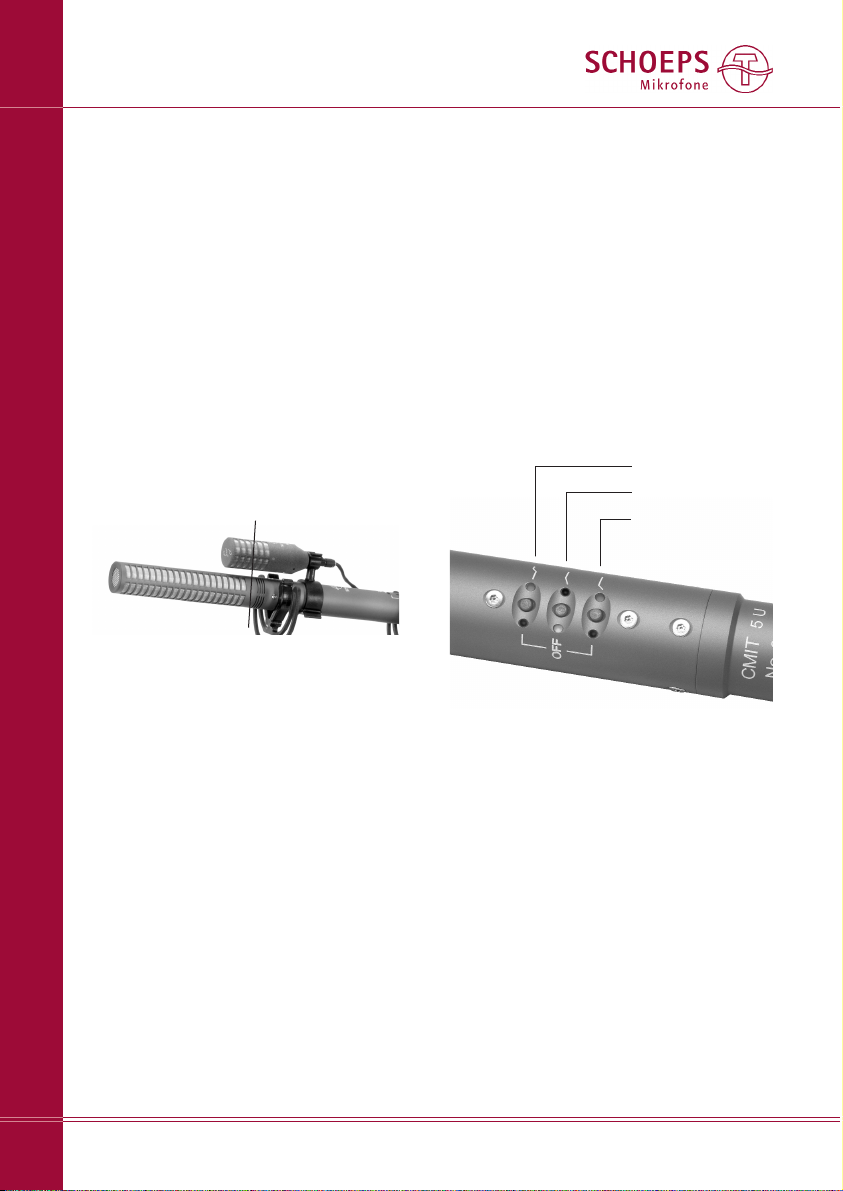
When mounting a figure-8 microphone or
capsule on a shotgun microphone, one should
be sure to place their diaphragms one directly
above the other, remembering of course that
the diaphragm of a shotgun microphone is at
the base of the interference tube, not at its tip.
Filters
The CMIT 5 U has three switchable filters. Each
is activated or deactivated by pressing a button.
They can be used to suppress low frequencies
or to boost high frequencies.
The two low-frequency filters start working
from 80 Hz and 300 Hz. However, even when
these are both switched off, there is another
low filter active below 40 Hz at a slope of
6 dB/oct. The steep low-cut filter below 80 Hz
(18 dB/oct.) suppresses wind and boom noise.
The filter below 300 Hz (6 dB/oct.) is a gentle
roll-off that compensates for proximity effects
(elevation of low frequencies by directional
microphones in near-field use). They also protect against disturbing, inaudible (infra-)sound
that can be caused by ventilation systems,
track vehicles and wind. What is tricky about
this is that although it is hardly noticeable,
infrasound can cause strong audible distortions
in the connected equipment when it leads to
an overload. This would make it impossible to
produce a useable record.
A high-frequency emphasis compensates
80 Hz, 18 dB/oct.
300 Hz, 6 dB/oct.
+5 dB at 10 kHz
M/S arrangement with shotgun microphone
(shown here: CMIT 5 U with CCM 8 and KMSC
double clip.)
The membranes of the two microphones
must be aligned one above the other; the black
line indicates their location.
Make sure all of the slits in the tube (sound
inlet openings) are free and uncovered when
using the microphone. Covering slits can alter
the sound and directivity of the microphone.
* Reverberation radius (”critical distance”): A sound
source generates a certain level of direct sound energy
which diminishes strongly as a function of distance.
If the sound is occurring in a room, some amount of
diffuse sound energy will be built up by repeated
reflections from acoustic barriers (mainly walls).
The level of diffuse sound in any given part of the
room will depend less on the distance from the sound
source than is the case for the level of direct sound.
In the theoretically ideal case, the level of diffuse sound
would be the same everywhere in the room.
The distance at which the reflected sound reaches
an equal level to the direct sound is called the reverberation radius. (”Radius” is used because we assume
that sound from a point source will spread out in a
spherical manner.)
Page 19
SCHOEPS GmbH · Spitalstr. 20 · D-76227 Karlsruhe (Durlach) · Tel: +49 721 943 20-0 · Fax: +49 721 943 2050
www.schoeps.de · [email protected]
Start up/ Phantom Powering
19
English
for high-frequency loss caused by windscreens
and enhances speech intelligibility.
Pairs of LEDs next to each pushbutton indicate the status of the filters. Green means
“Filter is OFF”, which means constant frequency
response curve. Red means “Warning, filter is
ON”. The settings are retained when the
microphone is switched off.
The LEDs next to each pushbutton let the
operator know the filter settings and whether
the microphone is on, even in the dark.
Start-Up / Phantom Powering
The CMIT 5 U is a condenser microphone. It is
built as a combination of two main components: a capsule and a microphone amplifier.
The capsule is the component that converts
sound waves into a varying electrical voltage.
It determines the directionality and, for the most
part, the sound quality of the microphone.
The amplifier of the CMIT 5 U possesses an
electronic circuit needed to polarize (charge)
the capacitive capsule. This hardly influences
the signal, since it only amplifies it, making it
low-impedance so that it can be sent through
a cable. The output is electrically balanced, in
order to eliminate electromagnetic interference
in the cable. This prevents "AC hum“, for
example. Filters cut out high frequencies picked
up by the cable (e.g. from mobile phones).
The microphone amplifier of the CMIT 5 U
has a transformerless, class-AB output stage
without condensers. This is what allows the
low impedance, low distortion and small size.
Start-Up
The CMIT 5 U is an electrically active component which requires operating current. This will
most often be supplied by the inputs of a mixer,
preamplifier (such as the SCHOEPS VMS 5U)
or recorder with suitable microphone powering built in.
Like most modern, solid-state professional
microphones, the CCM also uses a standardized powering scheme known as “phantom
powering.” Most recording equipment offers
a 48-Volt supply for such microphones.
Our microphones are developed and tested
with power supplies that conform to the
require ments of this standard. Proper operation
with non-standard power supplies cannot be
guaranteed. Circuit arrangements that deviate
from the standard can cause operational problems (i.e. distortion or even gaps in the signal),
particularly at high sound pressure levels or in
the presence of strong wind noise. Such problems may often seem to defy analysis until
their real cause is discovered.
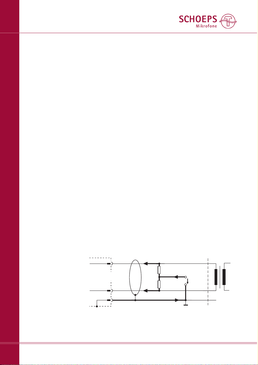
Fig. 1
Input with transformer
(or balanced, ungrounded
transformerless input)
+ phase
- phase
2 (4)
3 (5)
microphone
1
screen
cable
powering
R
S
U
S
input
R
S
P48: US= 48 V ± 4 V; RS= 6,8 kW*, I
max.
= 10 mA
I/2
I/2
I
* Tolerance: ±20%, however, the differ-
ence between the resistors of any one pair
should be less than 0.4% (i.e. 27 Ohms)
XLR-3
Connector
Shield
Microphone
+ Phase
- Phase
Cable
Powering
Input
Page 20

SCHOEPS GmbH · Spitalstr. 20 · D-76227 Karlsruhe (Durlach) · Tel: +49 721 943 20-0 · Fax: +49 721 943 2050
www.schoeps.de · [email protected]
Phantom Powering
20
English
Phan tom Po we ring to Stan dard
DIN EN 61938
“Phantom” powering is the standard way to
power condenser microphones. It works using
a two-conductor, shielded cable. Both conductors are under the same voltage, and exactly
the same current flows through both of them.
Fig. 1 shows the only valid 48 V phan tom
powering circuit (abbreviation: P48) that can
be built using resistors as opposed to a centertapped input transformer. This illustration is
based on the international standard document
EN 61938 from 1997.
The permissible tolerance of the feed resistor
values as such is ±20%. However, the difference between the resistors of any one pair
should be less than 0.4% (i.e. 27 Ohms). This
close matching is necessary to maintain adequate impedance balance for the sake of common mode rejection. It also avoids the flow of
DC in an input transformer should one be
present, which could lead to distortion or a
reduced dynamic range.
A microphone designed for 48 V phantom
powering may draw as much as 10 mA according to the standard; a SCHOEPS CMIT 5 U will
draw about 4 mA. This falls well within the limit
set by the prevailing standard.
Although there is nothing particularly complicated or demanding about phantom powering,
there are certain commercially available power
supplies, preamplifiers, and mixing desks –
mostly older, but some more recent – which
fail to meet this standard and hence may not
be able to power SCHOEPS microphones adequately. If in doubt, equipment should be
checked to verify its suitability for professional
work with SCHOEPS microphones. A quick and
easy way to check a phantom supply is
described on page 26.
Unbalanced Operation
You may encounter a situation in which there
is no balanced input with phantom power
available, but only an unbalanced input –
probably even unpowered. If the latter is the
case, a standalone P48 supply with balanced
in-/ouputs should be used before this input.
If the input has got phantom powering but
is unbalanced, the temptation may be
great, but we strongly advise against using
it on the CMIT 5 U, since this microphone
is not designed for such operation, and
the advantages of phantom powering
(noise and interference rejection) will be
completely lost. Instead, a high-quality
microphone input transformer should be used
to turn an unbalanced into a balanced input.
This will allow the signal leads from the microphone to be kept balanced, for best rejection
of interference.
If you have no choice but to go ahead
despite the disadvantages of an unbalanced
signal, then you can set up your system for
unbalanced operation by uncoupling the signal
on pin 2 using a capacitor (rating: 100 µF, 63 V
at R= 22 kΩ). There is no signal on pin 3.
Nevertheless, it must still be ensured that the
microphone is fed over all three pins. With the
CMIT 5 U, this operating method does not alter
the signal-to-noise ratio.
Simultaneous Connection to Multiple Inputs
If a microphone has to be connected to multiple inputs simultaneously, an active micro phone
splitter should be used in order to preserve
the loading and powering conditions for the
microphone, and to prevent interference.
Ma xi mum Cable Length
In the typical application of a shotgun microphone, namely on a boom, cables of just a
few meters are used. The CMIT 5 U can be
connected to cables up to 300 m in length.
The practical limit depends on the electrical
capacitance of the cable, which is sometimes
an unknown quantity. The lower this capacitance is per unit length, the longer the cable
can be. All SCHOEPS cables have very low capacitance (100 pF/m between the conductors).
The main risks with excessively long microphone cables are gradual losses at high frequencies due to the cable capacitance, some
reduction in ability to handle very high sound
pressure levels, and increased pickup of interference.
Page 21

Notes on Electromagnetic Compatibility
SCHOEPS CMC microphone amplifiers are virtually immune to magnetic, electric and electromagnetic fields.
Due to the wide dynamic range of studio
microphones, the smallest signal amplitudes
are in the microvolt range (1/1,000,000 Volt).
Cable shielding and the grounding scheme of
the preamp or mixer input are also crucial.
A microphone can therefore never be expected
to be immune to all possible disturbances in all
circumstances, but the following suggestions can
help to reduce any noise induction:
1) Keep both the microphone and the cable
away from sources of interference such as
monitors, digital equipment (computers),
RF emitters (mobile phones and other per-
sonal communication devices that emit radio
frequency energy), power transformers,
power lines, SCR dimmers, switching power
supplies etc.
2) Use only high-quality cables with a high
degree of shield coverage, e.g. SCHOEPS
K EMC 5 U.
3) Keep all cables as short as possible.
4) Dress audio cables away from power cables.
If they must cross, it should be at right angles.
5) At the preamp or mixer input, the shield of
the microphone cable should connect to the
chassis ground in the shortest way possible.
If necessary, this coupling can be capacitive.
SCHOEPS GmbH · Spitalstr. 20 · D-76227 Karlsruhe (Durlach) · Tel: +49 721 943 20-0 · Fax: +49 721 943 2050
www.schoeps.de · [email protected]
Hints on Avoiding Interference
21
English
Page 22
SCHOEPS GmbH · Spitalstr. 20 · D-76227 Karlsruhe (Durlach) · Tel: +49 721 943 20-0 · Fax: +49 721 943 2050
www.schoeps.de · [email protected]
Troubleshooting
22
English
Wind Noise and Windscreens
Air motion (wind, vocal “popping” on sung
or spoken consonants, motion of the microphone on a boom arm, or air currents due to
heating or air conditioning systems) can cause
noise that should always be dealt with. Even if
it doesn't cause overload, it will detract from
the clarity of sound. A wind or pop screen
should be used, but should be chosen carefully
to avoid changing the microphone's characteristics too much. Many screen types that are
effective at reducing wind noise also have a
tendency to reduce a microphone's directionality and/or its high-frequency response. Baskettype windscreens mainly cause some unevenness in the frequency response, while foam
windscreens mainly tend to dampen high frequencies.
Vibration
If noise from mechanical vibration is going to
reach a stand- or boom-mounted microphone,
a shock mount (elastic suspension) should be
used, and a loop of slack cable isolated and
tied off so that it does not become another way
for vibra tions to reach the microphone. Unlike
a windscreen, a shock mount will not affect
the characteristics of a microphone. In many
kinds of work it is well justified to use a shock
mount ”by default”.
Overload
If transient or continual overload occurs, or
seems likely to occur, it is useful to think of the
complete set of equipment used for a recording or broadcast as a succession of ”stages”.
The signal should then be attenuated (its level
decreased) at the input to the first stage of
equipment that might be overloaded. Reducing
the gain at any earlier stage would add unnecessary noise, while reducing it at a later stage
would not solve the problem.
A condenser microphone itself represents at
least two stages – the capsule and the ampli fier.
The only sound pressure that could overload a
SCHOEPS microphone capsule (150+ dB SPL)
would also damage human hearing almost
instantly; in practice our capsules are rarely
over loaded except by explosions or direct
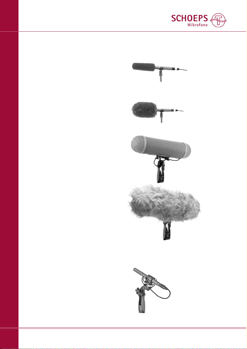
Foam windscreen W 140
(included accessory)
Fure-type windscreen “Softie”, 12 cm dia.
Basket-type windscreen WSR CMIT U with
Connbox included;
below: WSR CMIT U with WJ CMIT
Windjammer (must be ordered separately)
Windscreens for the CMIT 5 U:
Rycote “Softie Lyre Mount”
(40 cm long XLR-3 cable
included);
available as of June 2009
Page 23

exposure to very strong wind. As a rule such
overload will not damage the microphone;
even strong wind blowing directly against the
capsule membrane will not harm it unless the
forces involved are enormous. A properly
powered SCHOEPS CMIT 5 U shotgun microphone can normally handle 130+ dB sound
pressure levels. Such levels are hardly ever
reached by natural sound sources.
With a properly powered SCHOEPS micro-
phone not exposed to wind, any overloads will
occur far more often in a mixer or preamp's
input circuit than in the microphone itself. This
is particularly true with equipment that was
designed primarily for use with dynamic or
consumer-type microphones. Thus if distortion
can be heard when the cause is obviously not
wind, then one of the first tests might be to
plug in a balanced ”pad” (resistive attenuator
such as the SCHOEPS MDZ 10 or MDZ 20) at
the console or preamp input to see whether
that solves the problem. This type of pad is
superior to built-in pad switches.
Unfortunately, even with fully professional
equipment, ”overload” indicators cannot
always be relied upon to indicate input overload – many such indicators are wired only to
later stages in the circuitry.
If a preamp or mixer has an input sensitivity
control, it should be set for a good compromise
between avoiding input overload on the one
hand (sensitivity too high) and avoiding noise
on the other (sensitivity too low). Ideally a
mixer or preamp should not add any noise of
its own to a microphone's signals, but a dB or
two of hiss is better than gross distortion
caused by clipping.
Low-frequency disturbances such as wind
or vibration may not be perceived directly
(subsonic noise), but can still cause overload
in some stage of the signal chain. Low-frequency noise can be effectively suppressed
using the Active in-line low-cut Filters LC 60
and LC 120. They can be placed between the
output of the microphone cable and the phantom-powered input of a mixer, preamp or
recorder, thus protecting that input from
overload.
Any other overload for which there seems
to be no sensible explanation may actually be
a symptom of incorrect or inadequate microphone powering. Powering systems and their
requirements are discussed near the beginning of this User Guide on page 19.
The most appropriate and most helpful troubleshooting tools are:
– a well-known good microphone cable
– a simple pop screen such as the SCHOEPS
W 140 (or for outdoor recording, a wind
screen such as the SCHOEPS WSR CMIT U)
– a balanced, in-line resistive attenuator (”pad”)
such as the SCHOEPS MDZ 10 or MDZ 20
– an ordinary multimeter or the SCHOEPS
PHS 48 phantom power tester
SCHOEPS GmbH · Spitalstr. 20 · D-76227 Karlsruhe (Durlach) · Tel: +49 721 943 20-0 · Fax: +49 721 943 2050
www.schoeps.de · [email protected]
Troubleshooting
23
English
LC 60 or LC 120
Active in-line lowcut Filter
PHS 48 phantom
power tester
MDZ 10 resistive
attanuator
Page 24

Care and Maintenance
Please take care to avoid placing the microphone in a dusty environment. Keep it in its
case (e.g. the wood carrying case it comes with)
when not in use, since any dust that gets inside
the capsules can adversely affect its functioning. Dust can affect the microphone in the
following way: In combination with humid ity
it can lead to condensation and thus popping
and crackling noises (often described as “frying sounds”).
What to do if …
the microphone is noisy (clicks and pops) in high
humidity?
If the microphone is brought in from the cold
outdoors to a warm (and humid) environment,
snapping or clicking noises can result from the
condensation of moisture. In this event the
microphone should be given between 30 and
60 minutes to warm up, and will then generally
perform flawlessly.
If this treatment does not eliminate the noise,
it is possible that dirt has gotten inside the
transducer (capsule) itself – in which case the
microphone must be sent back to the factory
for cleaning. We strongly advise customers
not to open a microphone or attempt to clean
it themselves. Doing so would also invalidate
all warrantees.
Windscreens are recommended when microphones have to be used in dirty or dusty environments in order to avoid problems of the
kind described above.
SCHOEPS GmbH · Spitalstr. 20 · D-76227 Karlsruhe (Durlach) · Tel: +49 721 943 20-0 · Fax: +49 721 943 2050
www.schoeps.de · [email protected]
Care and Maintenance
24
English
Page 25
SCHOEPS GmbH · Spitalstr. 20 · D-76227 Karlsruhe (Durlach) · Tel: +49 721 943 20-0 · Fax: +49 721 943 2050
www.schoeps.de · [email protected]
Technical Specifications
25
English
Directional pattern: . . . . . . . . . . . .Supercardioid / lobe-shaped
Frequency range: . . . . . . . . . . . . .40 Hz – 20 kHz
Switchable filters: . . . . . . . . . . . . .80 Hz with 18 dB/oct.,
300 Hz with 6 dB/oct.,
5 dB lift at 10 kHz (shelving)
Sensitivity: . . . . . . . . . . . . . . . . . .17 mV/Pa
Equivalent noise level (filters off): . .14 dB-A*, 24 dB CCIR**
Maximum sound pressure level: . .132 dB SPL at 0.5% THD
Polarity: . . . . . . . . . . . . . . . . . . . .An excursion of the diaphragm towards the back electrode
(positive pressure phase) leads to a positive signal at pin 2.
Powering: . . . . . . . . . . . . . . . . . .48 V ± 4 V phantom
Current consumption: . . . . . . . . .4.4 mA
Maximum output voltage: . . . . . .1.3 V (at 1 kHz, 1 kOhms)
Output impedance: . . . . . . . . . . .50 Ohms
Recommended load impedance: . .600 Ohms or greater
Dimensions: . . . . . . . . . . . . . . . . .Length: 251 mm,
Diameter: 21 mm
Weight: . . . . . . . . . . . . . . . . . . . .Only 89 g (3-1/8 ounces)
Surface finish: . . . . . . . . . . . . . . . .Anodized
Technical Specifications:
From outer
to inner:
250 Hz 4 kHz
500 Hz 8 kHz
1 kHz 16 kHz
2 kHz
* According to IEC 61672-1
** According to IEC 60268-1
Polar diagram
Frequency response curve without filters at 0°, 30°, 60°, 90°
angle of incidence
Frequency response (tolerances shown)
Frequency response curve:
1) Without filters 2) 80 Hz, 18 dB/oct.
3) 300 Hz, 6 dB/oct. 4) 80 Hz + 300 Hz 5) 10 kHz: +5 dB
20 50 100 200 500 1k 2k 5k 10k 20kHz
+10
-10
0dB
-20
20 50 100 200 500 1k 2k 5k 10k 20kHz
+10
-10
0dB
-20
20 50 100 200 500 1k 2k 5k 10k 20kHz
+10
-10
0dB
-20
30°
60°
90°
1
2
3
4
5
1
Page 26
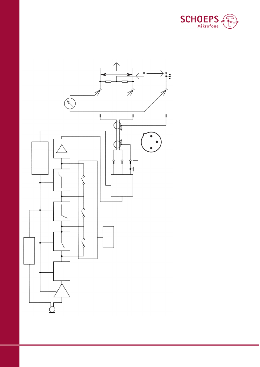
DC generator
regulator
micro controller, LEDs
preamp
impedance
converter
filter 1
push-
buttons
filter 2 filter 3
output
stage
RFI
filter
[1] +Phase: an excursion of the diaphragm towards the back electrode
(positive pressure phase) leads to a positive signal at this pin
[2] Matched (i.e. matching tolerance of only 0.7%), see page 19
[3] Here are three simple methods for verifying correct phantom powering.
These measurements should be made at an unused input. Reduce the
channel gain to the minimum to protect the loudspeakers, etc. If micro-
phones are connected to other inputs at the same time, no substantial
difference should occur in the results.
1. Measure the open-circuit voltage between ground (pin 1) and either
pin 2 or pin 3 of the XLR input. Given the permitted tolerances, this
voltage should be between 44 and 52 VDC for P48. Then, measure the
short-circuit current between ground (pin 1) and either pin 2 or pin 3 of
the XLR input. Given the permitted tolerances, this current should be
between 5.9 and 8.5 mA DC for P48.
Note: Well-designed phantom power supplies must tolerate at least a
temporary short circuit without damage; an unbalanced connection
(which is occasionally necessary) would cause the same current to be
drawn. To be safe, however, do not leave the short circuit closed for
any longer than necessary.
2) Measure the DC voltages on the modulation leads with a micro-
phone connected, e.g. by opening the connector shell of the cable. The
two voltages (from pin 2 and pin 3 to pin 1) must be identical. They
should be about 33 Volts (minimum = 29 Volts).
3) For P48, use a SCHOEPS PHS 48 tester. Plug it in; if the LED glows and
stays lit, all is well.
3
1
2
Phantom-
powering
[3]
U
s
= +48 V
R
s
[2]= 6.8 kΩ
R
s
[2]= 6.8 kΩ
Preampli -
fier,
recorder
or mixing
desk
∼
∼
screen
-phase
+phase
XLR-3
connector
XLR-3
connector
Pin 1: screen (GND)
Pin 2: +phase[1]
Pin 3: –phase
Bottom view
(as the pins are seen)
1
2
3
Microphone -
cable
[3]
SCHOEPS GmbH · Spitalstr. 20 · D-76227 Karlsruhe (Durlach) · Tel: +49 721 943 20-0 · Fax: +49 721 943 2050
www.schoeps.de · [email protected]
Block Diagram of the CMIT 5 U
26
English
Page 27

Warranty
We guarantee our products for a period of
twenty-four months. The warrantee period
begins on the date of purchase.
Please provide your bill of sale in all cases
as proof of warrantee; without it, repairs will
be undertaken only at the owner’s expense.
We reserve the right to satisfy all warranty
requirements regarding defects of workmanship or materials by means of repair or partial
or complete replacement of the product, at
our sole discretion.
Excluded from this warrantee are defects
due to misuse (e.g. incorrect operation;
mechanical damage), abuse or “acts of God”.
This warrantee becomes void in the event of
tampering by unauthorized persons or agencies.
To secure your rights under this warrantee,
send the product with proof of purchase and
a precise description of the malfunction, at your
expense, either to SCHOEPS (if you are a customer in Germany), or to our representative
(if you are a customer outside Germany).
Prior to sending your defective product for
repair, please contact your local dealer or distributor for instructions. In exceptional cases
you can, by prior arrangement with SCHOEPS,
send the product directly to us from a foreign
country.
This warrantee does not affect any contractual agreements which may exist between the
buyer and seller of the equipment.
This warrantee is world-wide.
Declaration of Conformity – CE-Mark
The CE-mark guarantees that all products
conform to relevant standards approved by
the European Community. The products
described in this User Guide comply with current, relevant standards when used with
cables from SCHOEPS.
Relevant directives:
EMC Directive: 89/336/EEC, amended by
92/31/EEC and 93/68/EEC
Relevant standards:
EN 55 103-1, -2 and those referred to by
them.
SCHOEPS GmbH · Spitalstr. 20 · D-76227 Karlsruhe (Durlach) · Tel: +49 721 943 20-0 · Fax: +49 721 943 2050
www.schoeps.de · [email protected]
Warranty, Declaration of Conformity
27
English
Page 28

Änderungen und Irrtümer vorbehalten.
Not responsible for errors or omissions.
Subject to change without notice.
090201
Technik
Schall
SCHOEPS GmbH
Spitalstr. 20
D-76227 Karlsruhe (Durlach)
Germany
Tel: +49 (0)721 943 20-0
Fax: +49 (0)721 943 2050
www.schoeps.de
[email protected]
 Loading...