

Schneider Electric Systems Canada MR450-X003 User Manual

M Series Data Radio – User Manual
User Manual
M Series Data Radio
MR450 Remote Data Radio
Incorporating compatible
EB450 Base Station & EH450 Hot Standby Base Station
© Copyright 2004 Trio DataCom Pty. Ltd.
www.trio.com.au
Issue 1: August 2004
Page 1

M Series Data Radio – User Manual
Contents
SECTION 1 3
Part A – Preface 4
Warranty 4
Important Notice 4
Warning - RF Exposure 4
Related Products 5
Other Related Documentation and Products 5
Revision History 5
Part B – M Series Overview 6
Definition of M Series Data Radio 6
M Series Product Range 6
M Series – Features and Benefits 6
Model Number Codes 7
Standard Accessories 8
Part C – Applications 9
Application Detail 9
Systems Architecture 10
Part D – System Planning and Design 12
Understanding RF Path Requirements 12
Examples of Predictive Path Modelling 13
Selecting Antennas 15
Data Connectivity 16
Power Supply and Environmental Considerations 19
Physical Dimensions - Remote Data Radio - MR450 20
Physical Dimensions - Base Station - EB450 21
Physical Dimensions - Hot Standby Base Station - EH450 22
SECTION 2 39
Part H – TVIEW+ Management Suite Programmer 40
Introduction 40
Installation 40
TVIEW+ Front Panel 41
Programmer 41
Part I – Specifications 49
MR450 Specifications 49
EB450 Specifications 50
EH450 Specifications 51
Part J – Support Options 52
Website Information 52
E-mail Technical Support 52
Telephone Technical Support 52
Contacting the Service Department 52
Part E – Getting Started 23
MR450 Quick Start Guide 23
EB450 Quick Start Guide 29
EH450 Quick Start Guide 32
Part F – Commissioning 37
Power-up 37
LED Indicators 37
Data Transfer Indications 37
Antenna Alignment and RSSI Testing 37
Link Establishment and BER Testing 37
Part G – Maintenance 38
Routine Maintenance Considerations 38
Page 2
© Copyright 2004 Trio DataCom Pty. Ltd.

M Series Data Radio – User Manual
SECTION 1
Part A - Preface
Part B - M Series Overview
Part C - Applications
Part D - System Planning and Design
Part E - Getting Started
Part F - Commissioning
Part G - Maintenance
© Copyright 2004 Trio DataCom Pty. Ltd.
Page 3

M Series Data Radio – User Manual
Part A – Preface
Warranty
Part A - Preface
All equipment supplied by Trio DataCom Pty Ltd is covered by
warranty for faulty workmanship and parts for a period of twelve (12)
months from the date of delivery to the customer. During the warranty
period Trio DataCom Pty Ltd shall, at its option, repair or replace faulty
parts or equipment provided the fault has not been caused by misuse,
accident, deliberate damage, abnormal atmosphere, liquid immersion
or lightning discharge; or where attempts have been made by
unauthorised persons to repair or modify the equipment.
The warranty does not cover modifications to software. All equipment
for repair under warranty must be returned freight paid to Trio DataCom
Pty Ltd or to such other place as Trio DataCom Pty Ltd shall
nominate. Following repair or replacement the equipment shall be
returned to the customer freight forward. If it is not possible due to the
nature of the equipment for it to be returned to Trio DataCom Pty Ltd,
then such expenses as may be incurred by Trio DataCom Pty Ltd in
servicing the equipment in situ shall be chargeable to the customer.
When equipment for repair does not qualify for repair or replacement
under warranty, repairs shall be performed at the prevailing costs for
parts and labour. Under no circumstances shall Trio DataCom Pty
Ltd’s liability extend beyond the above nor shall Trio DataCom Pty
Ltd, its principals, servants or agents be liable for the consequential
damages caused by the failure or malfunction of any equipment.
Important Notice
Warning - RF Exposure (FCC/IC)
The radio equipment described in this user manual emits low level
radio frequency energy. Professional installation is required. The
concentrated energy may pose a health hazard depending on the type
of antenna used.
This device is intended for FIXED installation conditions. DO NOT
allow people to come within 2 metres (6.6 feet) of non-directional
antennas and 6 metres (20 feet) from the front of directional antennas
when the transmitter is operating.
More information is available from www.fcc.gov/oet/info/documents/
bulletins
© Copyright 2004 Trio DataCom Pty Ltd All Rights Reserved
This manual covers the operation of the M Series of Digital Data
Radios. Specifications described are typical only and are subject to
normal manufacturing and service tolerances.
Trio DataCom Pty Ltd reserves the right to modify the equipment, its
specification or this manual without prior notice, in the interest of
improving performance, reliability or servicing. At the time of
publication all data is correct for the operation of the equipment at the
voltage and/or temperature referred to. Performance data indicates
typical values related to the particular product.
This manual is copyright by Trio DataCom Pty Ltd. All rights
reserved. No part of the documentation or the information supplied
may be divulged to any third party without the express written
permission of Trio DataCom Pty Ltd.
Same are proprietary to Trio DataCom Pty Ltd and are supplied for the
purposes referred to in the accompanying documentation and must not
be used for any other purpose. All such information remains the
property of Trio DataCom Pty Ltd and may not be reproduced, copied,
stored on or transferred to any other media or used or distributed in
any way save for the express purposes for which it is supplied.
Products offered may contain software which is proprietary to Trio
DataCom Pty Ltd. However, the offer of supply of these products and
services does not include or infer any transfer of ownership of such
proprietary information and as such reproduction or reuse without the
express permission in writing from Trio DataCom Pty Ltd is forbidden.
Permission may be applied for by contacting Trio DataCom Pty Ltd in
writing.
Page 4
© Copyright 2004 Trio DataCom Pty. Ltd.

M Series Data Radio – User Manual
Related Products
ER450 Remote Data Radio
EB450 Base/Repeater Station
EH450 Hot Standby Base Station
Other Related Documentation
and Products
E Series Quick Start Guides
TVIEW+ Management Suite
Digital Orderwire Voice Module (EDOVM)
Multiplexer Stream Router (MSR)
Revision History
Issue 1 August 2004 Intitial Release
Part A - Preface
© Copyright 2004 Trio DataCom Pty. Ltd.
Page 5
M Series Data Radio – User Manual
Part B – M Series Overview
Part B – M Series Overview
Definition of M Series Data Radio
The M Series is a range of wireless modems designed for the
transmission of data communications for SCADA, telemetry and any
other information and control applications that utilise ASCII messaging
techniques. The M Series uses advanced “digital” modulation and
signal processing techniques to achieve exceptionally high data
throughput efficiency using traditional licensed narrow band radio
channels.
These products are available in many frequency band and regulatory
formats, to suit spectrum bandplans in various continental regions. The
range is designed for both fixed point to point (PTP), and multiple
address (MAS) or point to multipoint (PMP) systems.
M Series Product Range
The M Series range consists of the a half duplex “Remote” radio
modem and provision to use an E Series Base Station, including an
optional Hot Standby controller to control two base station units in a
redundant configuration.
Frequency band variants are indicated by the band prefix and model
numbering. (See Model Number Codes)
M Series – Features and Benefits
• 395-520 MHz band operation
• 0.1 to 5 watt transmitter output power
• Software selectable Tx and Rx frequencies
• Simplex or half duplex operation with any Tx-Rx splits
• One model suitable for 12.5 and 25 kHz channel spacing
• Synthesized digital data radio design
• High frequency stability
• Professional N Type antenna connector
• Separate versions for true 9600 bps or 2400/4800 bps over-air
data rates
• Fully integrated DSP based data modem
• High data integrity - CRC error checking
• User configurable 300-19,200 bps asynch RS-232 port
• Fully transparent 3 wire user interface
• Intelligent transmitter control - auto Tx on data
• Compatible with most industry standard data protocols, e.g.,
MODBUS, DNP-3, IEC 870-5-101 etc.
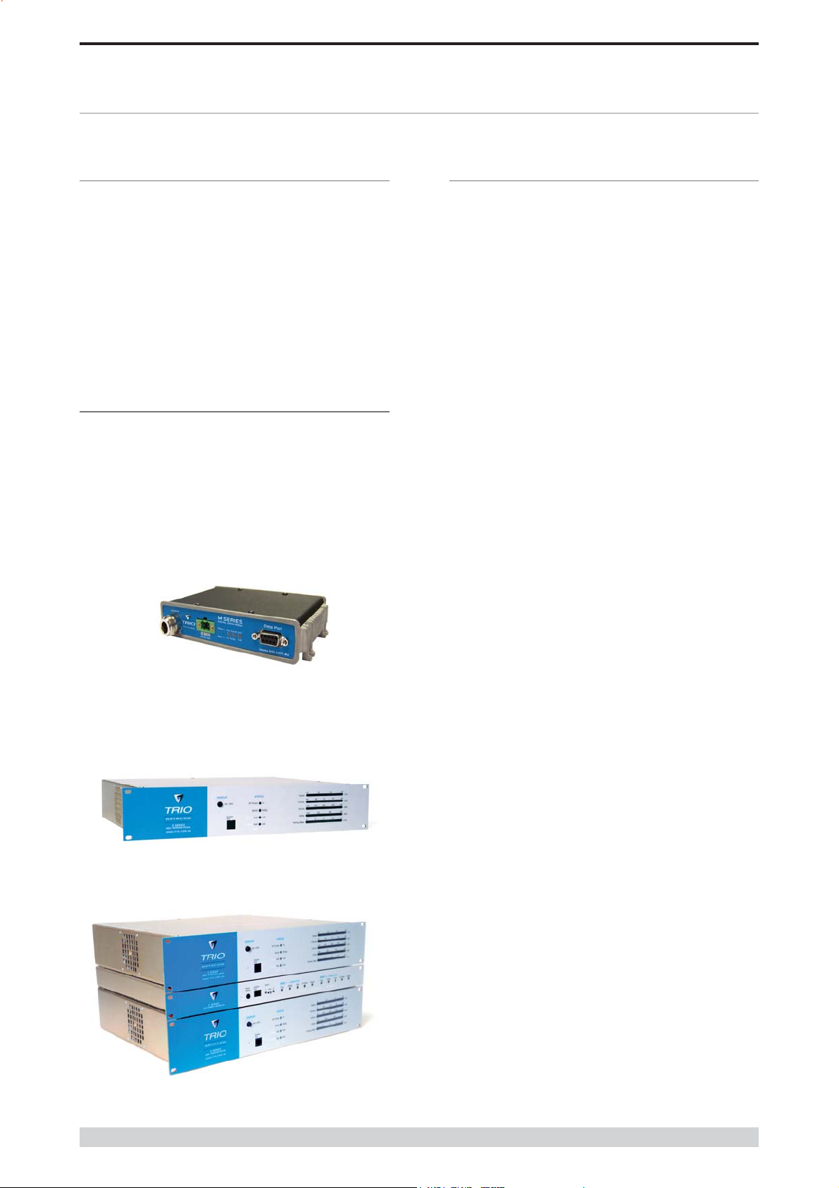
MR450 Remote Radio
EB450 Base / Repeater Station
• Multi-function bi-colour Tx/Rx data LEDs showing Port activity
(breakout box style), as well as LEDs indicating Tx, Rx, RF
Signal, Data Synchronisation and DC Power status of the
radio.
• Compatible with E-Series Base / Repeater Station (EB) and
Hot Standby Base Station (EH)
Page 6
EH450 Hot Standby Base Station
© Copyright 2004 Trio DataCom Pty. Ltd.
M Series Data Radio – User Manual
*
*
r
a
g
s
t
s
*
m
s
s
A
A
0
#
z
A02
2
A02
0
#
2
3
2
2
2
2
)
)
)
x
)
z
)
x
)
z
)
)
z
*
z
*
)
*
)
*
e
e
s
y
y
s
s
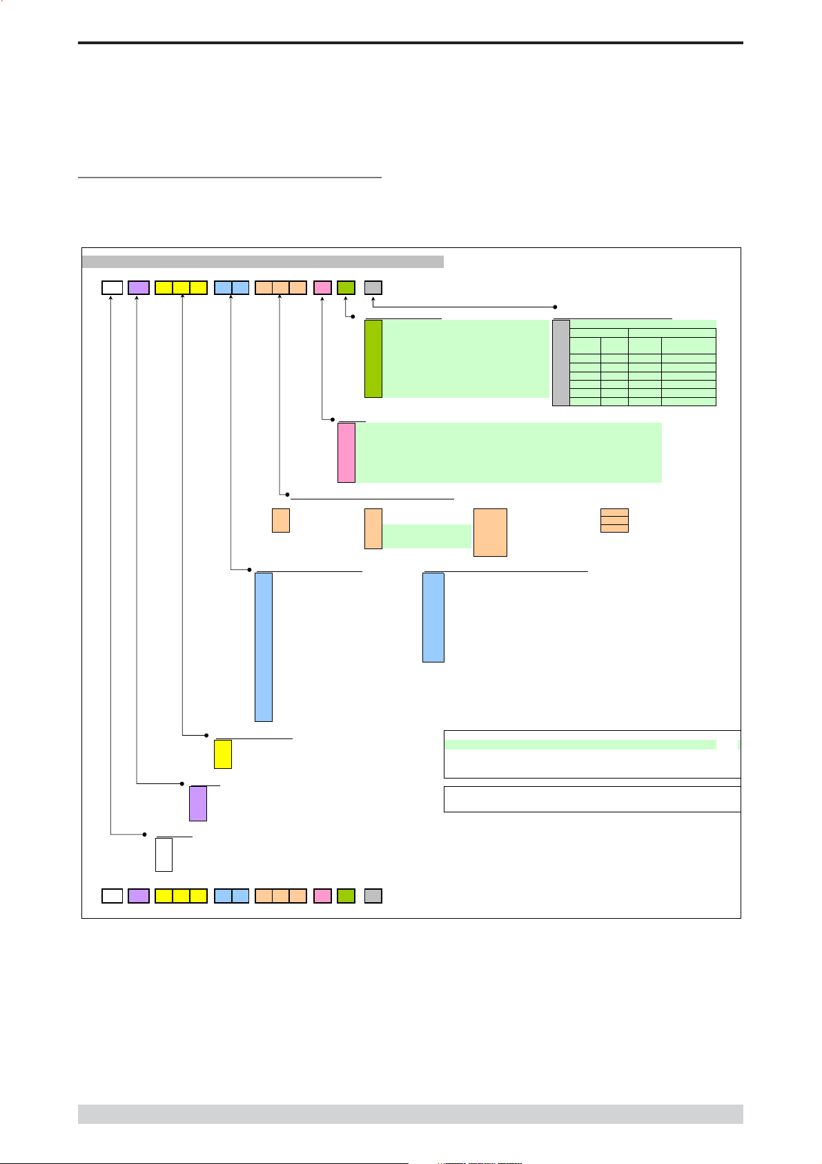
Model Number Codes
D, E, S & M Series Data Radios - Part Number Matrix = Tyxxx-aabbb-cde
T y xxx- aa bbb- cd e
Part B – M Series Overview
RF Channel Data Rate & Bandwidth (Internal Mode
D Serie
01
= ACA 4800bps 12.5kHz
= ACA 9600bps 25kHz
F01
= FCC 9600bps 12.5kHz
Frequency (200 & 400 MHz Bands
39= 208 to 240MHz (Tx & Rx
46= 370 to 388MHz (Tx & Rx
47= 380 to 396MHz (Tx & Rx
48 = 395 to 406MHz (Tx & Rx
50 = 403 to 417MHz (Tx & Rx
58 = (Tx) 406 to 421MHz (Rx) 415 to 430MH
59= (Tx) 415 to 430MHz (Rx) 406 to 421MH
56= 418 to 435MHz (Tx & Rx
57= 428 to 444MHz (Tx & Rx
55 = 436 to 450MHz (Tx & Rx) 18 = (Tx) 943 to 961MHz (Rx) 916 to 938MHz **
51 = 450 to 465MHz (Tx & Rx)
52 = 465 to 480MHz (Tx & Rx)
53 = 480 to 494MHz (Tx & Rx) Note: Other frequency bands available upon request.
60 = 490 to 500MHz (Tx & Rx)
54 = 505 to 518MHz (Tx & Rx)
27 = (Tx) 511 to 515MHz (Rx) 501 to 505MHz
M = 395 to 465MHz (Tx & Rx) (M Series Only)
H = 450 to 520MHz (Tx & Rx) (M Series Only)
Generic Frequency Band
200 = 208 to 245MHz (D & S Series only) * Additional charges apply. Must be ordered separately. Please refer to price list.
450 = 370 to 518MHz (E, M & S Series only)
900 = 800 to 960MHz (D & S Series only) [ ] Items in [ ] parenthesis refer to actual Trio part numbers
Unit Typ
R = Remote Station Standards:
B = Base / Repeater Station FCC - Federal Communications Commission
S = Standard Base / Repeater Station (D Series Only) ETSI - European Telecommunication Standards Institute
H = Hot Standby Base / Repeater (D, E & M Series Only)
Model Typ
D = D Series Family
= E Serie
Famil
= S Series Famil
Example:
E
M = M Series Family
S
E R 450- 51 A02- D0
Options - Base Stations
0 = No Options 0 = No Options
= 450MHz Band Reject
1
= 450MHz Band Reject
2
= 450MHz Band Pas
3
= 900MHz Band Rejec
4
= 900MHz Band Pas
5
= 900MHz Band Pass
6
Options
Note: Specify Internally or Externally fitted. Externally fitted duplexes require feeder tails.
0 = No Options
D = Diagnostics - [DIAGS/D, DIAGS/DH, DIAGS/E or DIAGS/EH, DIAGS/M] (D, E & M Series Only)
E = Hazardous Environment Class 1, Div 2 and Diagnostics [HAZ-APROVAL/M + DIAGS/M] (M Series)
N = Remote Fitted into NEMA Enclosure [NEMA 4/R]
F = Full Duplex Operation [ERFD450] (ER450 only)
X = Full Duplex Operation [ERFD450 & DIAGS/E] (ER450 only)
S = SMA Connector (SR450 Remote Only)
S Serie
001
= 12.5kHz (No Modem Fitted)
00
= 25kHz (No Modem Fitted)
241
= 2400bps in 12.5kHz [24SR]*
24
= 2400bps in 25kHz [24SR]*
48
= 4800bps in 25kHz [48SR]*
Typically Internal [DUPLX450BR]
(<9MHz split)[DUPLX450BR/5]
[DUPLX450BP]
Typically Internal [DUPLX900BR]
[DUPLX900BP]
(76MHz split)[DUPLX852/930]
E Serie
= ACA 480
01
= ACA 960
= FCC 9600#/ 19K2bps 12.5kHz
F01
F0
= FCC 19k2bps 25kHz
E01
= ETSI 9600bps 12.5kHz
E0
= ETSI 19k2bps 25kHz
Frequency (800 & 900 MHz Band) (D & S Series Only
07= (Tx) 847 to 857MHz (Rx) 923 to 933MHz (D Series only, 1W Full Duple
10 = (Tx) 848 to 858MHz (Rx) 920 to 934MH
06= (Tx) 923 to 933MHz (Rx) 847 to 857MHz (D Series only, 1W Full Duple
11 = (Tx) 920 to 934MHz (Rx) 848 to 858MH
12= 855 to 860MHz (Tx & Rx
14 = (Tx) 925 to 943MHz (Rx) 906 to 924MHz *
15= (Tx) 904 to 922MHz (Rx) 925 to 943MHz *
16= 924 to 944MHz (Tx & Rx) *
17= (Tx) 919 to 937MHz (Rx) 943 to 959MHz *
NOTES:
#
Provides compatibility with D Series radio
** Consult factory for availability.
ACA - Australian Communications Authority
The example shown specifies: E Series, Remote Radio, generic 450MHz band, with a specific frequency of
450MHz to 465MHz, a 96/19.2kbps modem, with a bandwidth of 25kHz, diagnostics and standard N type
connector.
Options - Hot Standby Configurations
Duplexe
Number Type
A - - - Separate Tx & Rx
B - - Dual [x4] Separate Tx & Rx
C Single Internal Single Combined Tx/Rx
D Dual [x2] Internal Dual [x2] Combined Tx/Rx
E Single External Single Combined Tx/Rx
F Dual [x2] External Dual [x2] Combined Tx/Rx
/ 9600bps 12.5H
/ 19k2bps 25kHz
Antenn
Antenna
Confi
M Serie
001
= 2400bps 12.5KHz / 4800bps 25kHz
00
= 4800bps 12.5KHz / 9600bps 25kHz
00
= FCC 9600bps 12.5KHz
NOTE: M Series Compatible EB/EH450 Base
Stations are Type A01 or F01
Antenna Type
Version: 4/04
© Copyright 2004 Trio DataCom Pty. Ltd.
Page 7

M Series Data Radio – User Manual
Standard Accessories
Part B – M Series Overview
Part Number Description
Duplexers
DUPLX450BR Duplexer BAND REJECT 400-520 MHz for use
with Base / Repeater / Links. For Tx / Rx
frequency splits >9MHz. (Fitted Externally for a
Link, Internally or Externally for Base / Repeater)
DUPLX450BR/5 Duplexer BAND REJECT 400-520 MHz for use
with Base / Repeater / Links. For Tx / Rx
frequency splits <9MHz. (Fitted Externally)
DUPLX450BP Duplexer PSEUDO BAND PASS Cavity 400-
520 MHz for External use with Base / Repeater /
Links.
Notes:
1. Frequencies must be specified at time of order.
2. Interconnecting (Feeder Tail) cables must be ordered
separately for Externally fitted Duplexers.
Antennas
ANT450/9A Antenna Yagi 6 Element 9dBd Aluminium 400-520
MHz c/w mtg clamps
ANT450/9S Antenna Yagi 6 Element 9dBd S/Steel 400-520
MHz c/w mtg clamps
ANT450/13A Antenna Yagi15 Element 13dBd Aluminium 400-
520 MHz c/w mtg clamps.
ANT450/13S Antenna Yagi 15 Element 13dBd S/Steel 400-520
MHz c/w mtg clamps.
ANTOMNI/4 Antenna Omnidirectional Unity Gain Side Mount
Dipole 400-520 MHz c/w galv. clamp
ANT450/D Antenna Omnidirectional Unity Gain Ground
Independent Dipole 400-520 MHz c/w 3m cable,
mounting bracket & BNC connector
ANT450/6OM Antenna Omnidirectional 6dBd 400-520 MHz c/w
mtg clamps
ANT450/9OM Antenna Omnidirectional 9dBd 400-520 MHz c/w
mtg clamps
Note:
1. Frequencies must be specified at time of order.
Power Supplies
RF Cables and Accessories
NM/NM/TL Feeder Tail - N Male to N Type Male 50cm fully
sweep tested
NM/NM/TLL Feeder Tail - N Male to N Type Male 1 metre fully
sweep tested
RFCAB5M 5.0m RG-58 type Antenna Feeder Cable
terminated with N type Male Connectors
RFCAB5M2 5.0m RG-213 type Antenna Feeder Cable
terminated with N type Male Connectors
RFCAB10M 10.0m RG-213 type Antenna Feeder Cable
terminated with N type Male Connectors
RFCAB20M 20.0m RG-213 type Antenna Feeder Cable
terminated with N type Male Connectors
RFCAB20M4 20.0m LDF4-50 type (1/2" foam dialectric)
Antenna Feeder Cable terminated with N type
Male Connectors
LGHTARRST Lightning Surge Arrestor In-line N Female to N
Female
Network Management Diagnostics
DIAGS/M Network Management and Remote Diagnostics
Facilities per Radio – M Series
DIAGS/E Network Management and Remote Diagnostics
Facilities per Radio – E Series for EB450
DIAGS/EH Network Management and Remote Diagnostics
Facilities – E Series for EH450
Software
TVIEW+ Configuration, Network Management and Remote
Diagnostics Software
Other
NEMA 4 /R Stainless Steel Enclosure for Remote Site
Equipment. Size 600mm (h) x 600mm (d) x
580mm (w) – Room for Third Party RTU / PLC
equip. (Approx. 400 (h) x 600 (d) x 580mm (w)
EDOVM Digital Order Wire Voice Module
ERFDTRAY 19" Rack Tray for Mounting of ER450 Full Duplex
Radio and External Band Reject Duplexer
TVIEW+MSeries M Series Programming Cable
PS13V82A Power Supply 13.8V 2A 240VAC
PS13V810A Power Supply Switch Mode 240VAC 13.8V 10A
for Base Stations – Battery Charge Capability
Part Number Description
Page 8
© Copyright 2004 Trio DataCom Pty. Ltd.

M Series Data Radio – User Manual
Part C – Applications
Part C – Applications
Generic Connectivity
The M Series has been designed for SCADA and telemetry
applications, and any other applications that use an ASCII
communications protocol, and which connect physically using the
RS232 interface standard (although converters can be used to adapt
other interfaces such as RS422/485, RS530/V35, G703 etc).
Any protocol that can be displayed using a PC based terminal
program operating via a serial communications port is suitable for
transmission by the M Series radio modems.
An ASCII protocol is any that consists of message strings formed
from ASCII characters, that being defined as a 10 or 11 bit block
including start and stop bits, 7 or 8 data bits and optional parity bit(s).
Port set-up dialog that includes the expressions “N,8,1”, or E,7,2” or
similar indicate an ASCII protocol.
Most of the dominant telemetry industry suppliers utilise proprietary
ASCII protocols, and also common 'open standard” industry protocols
such as DNP3, MODBUS, TCP/IP, and PPP. These are all ASCII
based protocols.
Industries and Applications
The M Series products are widely used in point-to-point and point-tomultipoint (multiple access) applications for remote interconnection of
PLCs, RTUs, dataloggers, and other data monitoring and control
devices - including specialist utility devices (such as powerline
ACRs). In addition, other applications such as area wide security and
alarm systems, public information systems (traffic flow and public
signage systems) and environmental monitoring systems.
Application Detail
SCADA Systems
This is where one or more centralised control sites are used to monitor
and control remote field devices over wide areas. Examples include
regional utilities monitoring and controlling networks over entire shires
or a greater city metropolis. Industry sectors include energy utilities
(gas and electricity distribution), water and sewerage utilities,
catchment and environment groups (rivers, dams and catchment
management authorities).
Telemetry Systems
Dedicated telemetry control systems interconnecting sequential
devices either where cabling is not practical or distances are
considerable.
Examples include:
• ore conveyor or slurry pipeline systems
• simple water systems (pump and reservoir interlinking)
• broadcast industry (linking studio to transmitter) etc.
Information Systems
Public Information systems such as freeway vehicle flow, travel time
monitoring, feedback signage, parking signage systems and
meteorological stations etc.
© Copyright 2004 Trio DataCom Pty. Ltd.
Page 9
M Series Data Radio – User Manual
Systems Architecture
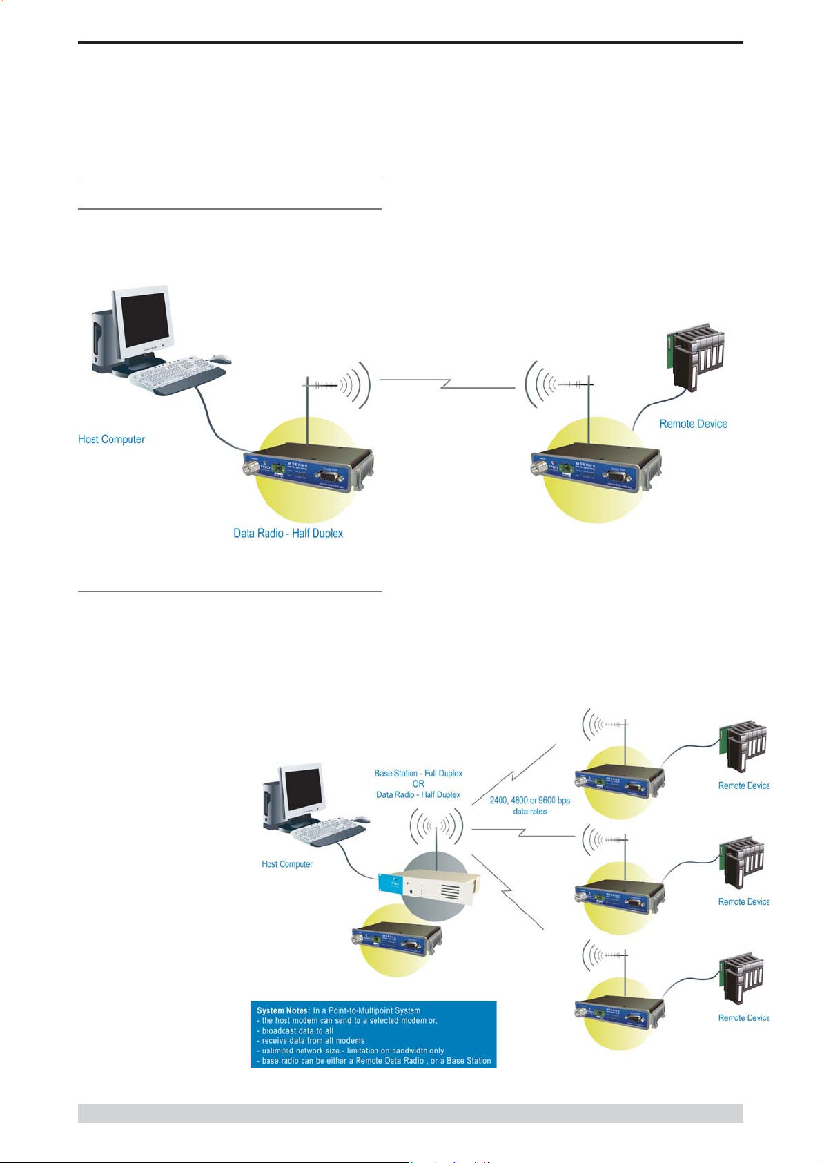
Point-to-Point
This simple system architecture provides a virtual connection between
the two points, similar to a cable. Operation is half-duplex.
Part C – Applications
Point-to-Multipoint Systems
In a multiple access radio system, messages can be broadcast from
one (master) site to all others, either using a half duplex radio system
or from any site to all others, using a simplex radio channel.
Half duplex systems often utilise a full duplex master (EB or EH), to
make the system simpler and for faster operation.
In either case, it will be necessary for
the application to support an
addressing system, since the master
needs to be able to select which
remote device it wishes to
communicate with. The radio system
operates “transparently”, allowing the
application’s protocol to provide the
addressing, and thus control the traffic.
Page 10
© Copyright 2004 Trio DataCom Pty. Ltd.
M Series Data Radio – User Manual
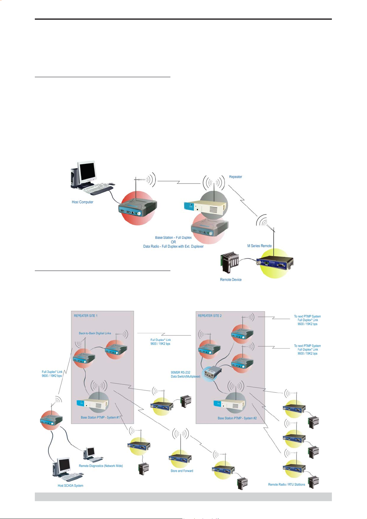
Digipeater Systems
This configuration is used where all sites are required to communicate
via a repeater site. A repeater site is used because it has a position
and/or height advantage and thus provides superior or extended RF
coverage. The radio modem at the repeater does not have to be
physically connected to the application’s master site. Information from
the application’s master is transmitted to the repeater via radio, and the
repeater then relays this information to the other field sites. In this
scenario, the repeater is the master from an RF point of view, and the
application master is effectively a “remote” from an RF point of view,
even though it is controlling the data transfer on the system.
Part C – Applications
E Series Backbone Store and Forward
Systems (Using M Series Remotes)
Store and forward is used as a way of extending RF coverage by
repeating data messages from one site to another.
Example shows E Series Backbone with E or M Series remotes.
© Copyright 2004 Trio DataCom Pty. Ltd.
Page 11

M Series Data Radio – User Manual
Part D – System Planning and Design
Part D – System Planning and Design
Understanding RF Path
Requirements
A radio modem needs a minimum amount of received RF signal to
operate reliably and provide adequate data throughput.
In most cases, spectrum regulatory authorities will also define or limit
the amount of signal that can be transmitted, and the transmitted power
will decay with distance and other factors, as it moves away from the
transmitting antenna.
It follows, therefore, that for a given transmission level, there will be a
finite distance at which a receiver can operate reliably with respect to
the transmitter.
Apart from signal loss due to distance, other factors that will decay a
signal include obstructions (hills, buildings, foliage), horizon (effectively
the bulge between two points on the earth), and (to a minimal extent at
UHF frequencies) factors such as fog, heavy rain-bursts, dust storms,
etc.
In order to ascertain the available RF coverage from a transmitting
station, it will be necessary to consider these factors. This can be
done in a number of ways, including
(a) using basic formulas to calculate the theoretically available
signal - allowing only for free space loss due to distance,
(b) using sophisticated software to build earth terrain models and
apply other correction factors such as earth curvature and the
effects of obstructions, and
(c) by actual field strength testing.
It is good design practice to consider the results of at least two of these
models to design a radio path.
Page 12
© Copyright 2004 Trio DataCom Pty. Ltd.
M Series Data Radio – User Manual
Part D – System Planning and Design
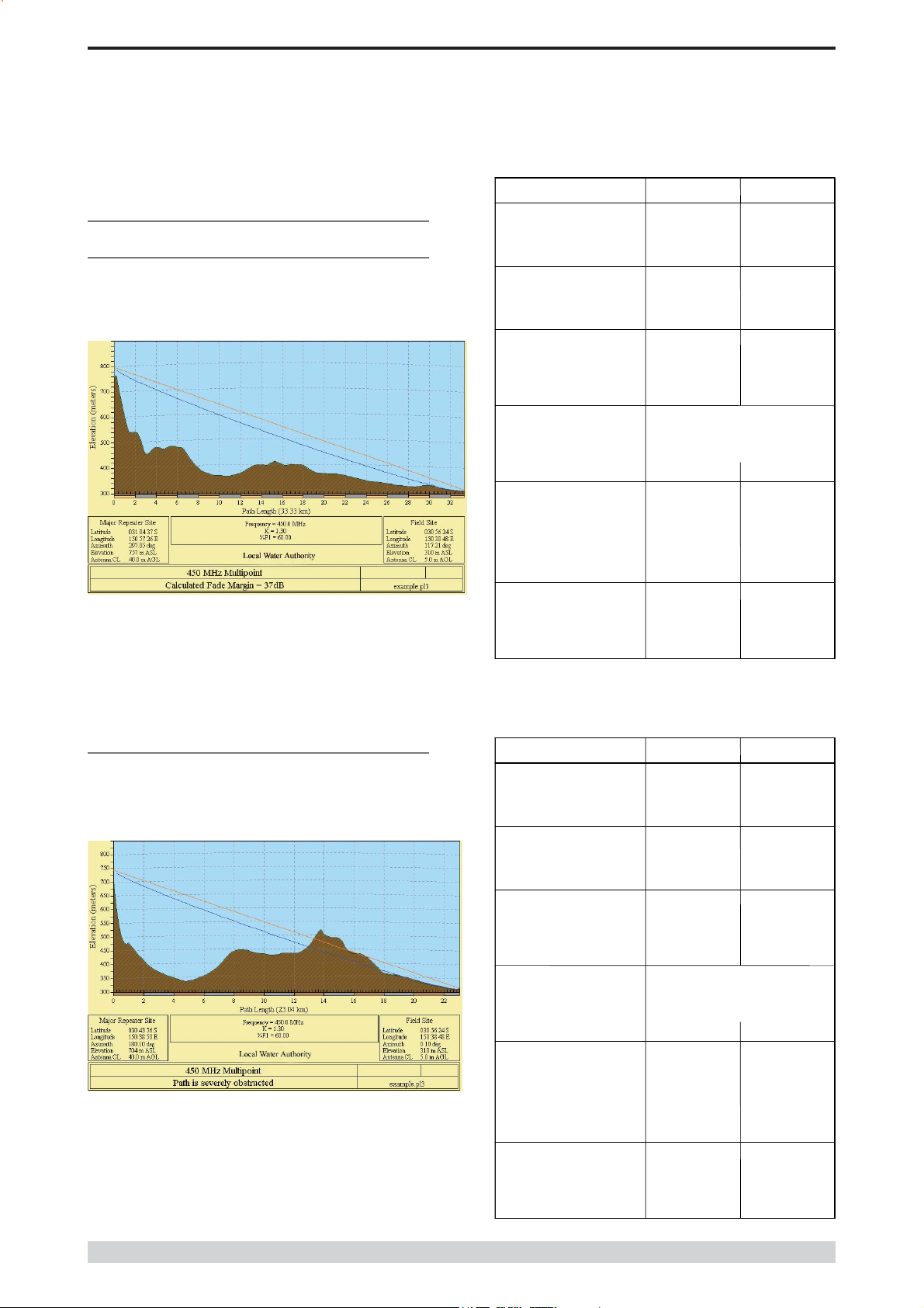
Examples of Predictive Path
Modelling
Clear line of site
Radio path with good signal levels, attenuated only by free space
loss.
goodpath.pl3 Major Repeater Site Field Site
Elevation (m)
Latitude 031 04 37.49 S 030 56 24.00 S
Longitude 150 57 26.34 E 150 38 48.00 E
Azimuth
Antenna Type ANT450/6OM ANT450/9AL
Antenna Height (m)
Antenna Gain (dBi)
Antenna Gain (dBd)
TX Line Type LDF4-50 LDF4-50
TX Line Length (m)
TX Line Unit Loss (dB/100 m)
TX Line Loss (dB)
Connector Loss (dB)
Frequency (MHz)
Path Length (km)
Free Space Loss (dB)
Diffraction Loss (dB)
Net Path Loss (dB)
Radio Type Model EB450 ER450
TX Power (watts)
TX Power (dBW)
Effective Radiated Power (watts)
Effective Radiated Power (dBW)
RX Sensitivity Level (uv)
RX Sensitivity Level (dBW) -140.00 -135.00
RX Signal (uv)
RX Signal (dBW) -103.75 -96.76
RX Field Strength (uv/m)
Fade Margin (dB)
Raleigh Service Probability (%)
756.69 309.67
297.05 117.21
40.00 5.00
8.15 11.15
6.00 9.00
40.00 5.00
6.79 6.79
2.72 0.34
2.00 2.00
450.00
33.33
115.99
0.00
103.75 103.75
5.00 1.00
6.99 0.00
6.71 4.63
8.27 6.66
0.71 1.26
45.93 102.70
453.14 545.42
36.25 38.24
99.976 99.985
Obstructed Radio Path
This path has an obstruction that will seriously degrade the signal
arriving at the field site.
obstpath.pl3 Major Repeater Site Field Site
Elevation (m)
Latitude 030 43 55.92 S 030 56 24.00 S
Longitude 150 38 49.51 E 150 38 48.00 E
Azimuth
Antenna Type ANT450/6OM ANT450/9AL
Antenna Height (m)
Antenna Gain (dBi)
Antenna Gain (dBd)
TX Line Type LDF4-50 LDF4-50
TX Line Length (m)
TX Line Unit Loss (dB/100 m)
TX Line Loss (dB)
Connector Loss (dB)
Frequency (MHz)
Path Length (km)
Free Space Loss (dB)
Diffraction Loss (dB)
Net Path Loss (dB)
Radio Type Model EB450 ER450
TX Power (watts)
TX Power (dBW)
Effective Radiated Power (watts)
Effective Radiated Power (dBW)
RX Sensitivity Level (uv)
RX Sensitivity Level (dBW) -140.00 -135.00
RX Signal (uv)
RX Signal (dBW) -117.25 -110.26
RX Field Strength (uv/m)
Fade Margin (dB)
Raleigh Service Probability (%)
703.83 309.67
180.10 0.10
40.00 5.00
8.15 11.15
6.00 9.00
40.00 5.00
6.79 6.79
2.72 0.34
2.00 2.00
450.00
23.04
112.78
16.71
117.25 117.25
5.00 1.00
6.99 0.00
6.71 4.63
8.27 6.66
0.71 1.26
9.70 21.70
95.74 115.23
22.75 24.74
99.470 99.665
© Copyright 2004 Trio DataCom Pty. Ltd.
Page 13
M Series Data Radio – User Manual
Part D – System Planning and Design
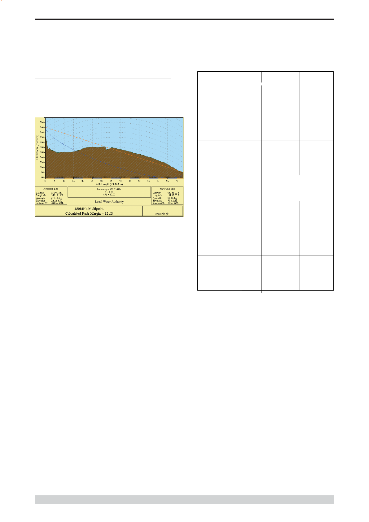
Effect of Earth Curvature on Long Paths
This path requires greater mast height to offset the earth curvature
experienced at such a distance (73km).
longpath.pl3 Repeater Site Far Field Site
Elevation (m)
Latitude 032 01 21.63 S 032 33 00.00 S
Longitude 142 15 19.26 E 141 47 00.00 E
Azimuth
Antenna Type ANT450/6OM ANT450/9AL
Antenna Height (m)
Antenna Gain (dBi)
Antenna Gain (dBd)
TX Line Type LDF4-50 LDF4-50
TX Line Len gth (m)
TX Line Loss (dB)
Connector Loss (dB)
Frequency (MHz)
Path Length (km)
Free Space Loss (dB)
Diffraction Loss (dB)
Net Path Loss (dB)
Radio Type Model EB450 ER450
TX Power (watts)
TX Power (dBW)
Effective Radiated Power (watts)
Effective Radiated Power (dBW)
RX Sensitivity Level (uv)
RX Sensitivity Level (dBW) -140.00 -135.00
221.26 75.58
217.12 37.37
40.00 5.00
8.15 11.15
6.00 9.00
40.00 5.00
6.79 6.79
2.72 0.34
2.00 2.00
450.00
73.46
122.85
22.94
133.55 133.55
5.00 1.00
6.99 0.00
6.72 4.64
8.27 6.66
0.71 1.26
RX Signal (uv)
RX Signal (dBW) -133.55 -126.56
RX Field Strength (uv/m)
Fade Margin (dB)
Raleigh Service Probability (%)
1.49 3.32
14.65 17.64
6.45 8.44
79.735 86.656
Page 14
© Copyright 2004 Trio DataCom Pty. Ltd.
M Series Data Radio – User Manual
Part D – System Planning and Design
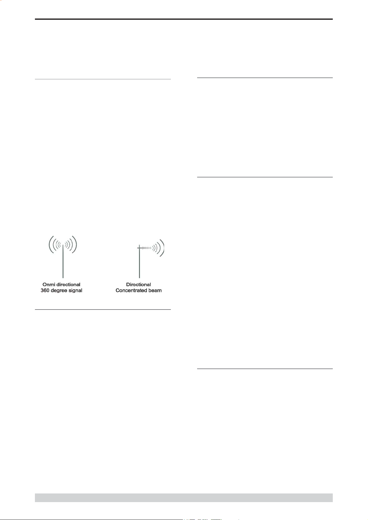
Selecting Antennas
There are basically two types of antennas – omni-directional and
directional.
Omnidirectional antennas are designed to radiate signal in a 360
degrees segment around the antenna. Basic short range antennas
such as folded dipoles and ground independent whips are used to
radiate the signal in a “ball” shaped pattern. High gain omni antennas
such as the “co-linear” compress the sphere of energy into the
horizontal plane, providing a relatively flat “disc” shaped pattern which
goes further because all of the energy is radiated in the horizontal
plane.
Directional antennas are designed to concentrate the signal into a
“beam” of energy for transmission in a single direction (i.e. for point-topoint or remote to base applications).
Beamwidths vary according to the antenna type, and so can be
selected to suit design requirements. The most common UHF
directional antenna is the yagi, which offers useable beam widths of
30-50 degrees. Even higher “gain” is available using parabolic “dish”
type antennas such as gridpacks.
Tuning the Antenna
Many antennas are manufactured for use over a wide frequency
range. Typical fixed use antennas such as folded dipoles and yagis
are generally supplied with the quoted gain available over the entire
specified band range, and do not require tuning. Co-linear antennas are
normally built to a specific frequency specified when ordering.
With mobile “whip” type antennas, it is sometimes necessary to
“tune” the antenna for the best performance on the required frequency.
This is usually done by trimming an antenna element whilst measuring
VSWR, or simply trimming to a manufacturer supplied chart showing
length vs frequency. These antennas would normally be supplied with
the tuning information provided.
Antenna Placement
When mounting the antenna, it is necessary to consider the following
criteria:
The mounting structure will need to be solid enough to withstand
additional loading on the antenna mount due to extreme wind, ice or
snow (and in some cases, large birds).
For omni directional antennas, it is necessary to consider the effect of
the mounting structure (tower mast or building) on the radiation pattern.
Close in structures, particularly steel structures, can alter the radiation
pattern of the antenna. Where possible, omni antennas should always
be mounted on the top of the mast or pole to minimise this effect. If this
is not possible, mount the antenna on a horizontal outrigger to get it at
least 1-2m away from the structure. When mounting on buildings, a
small mast or pole (2-4m) can significantly improve the radiation
pattern by providing clearance from the building structure.
Antenna Gain
By compressing the transmission energy into a disc or beam, the
antenna provides more energy (a stronger signal) in that direction, and
thus is said to have a performance “gain” over a basic omni antenna.
Gain is usually expressed in dBd, which is referenced to a standard
folded dipole. Gain can also be expressed in dBi, which is referenced
to a theoretical “isotropic” radiator. Either way, if you intend to send
and receive signals from a single direction, there is advantage in using
a directional antenna - both due to the increased signal in the wanted
direction, and the relatively decreased signal in the unwanted direction
(i.e. “interference rejection” properties).
For directional antennas, it is generally only necessary to consider the
structure in relation to the forward radiation pattern of the antenna,
unless the structure is metallic, and of a solid nature. In this case it is
also prudent to position the antenna as far away from the structure as
is practical. With directional antennas, it is also necessary to ensure
that the antenna cannot move in such a way that the directional
beamwidth will be affected. For long yagi antennas, it is often
necessary to install a fibreglass strut to stablilise the antenna under
windy conditions.
Alignment of Directional Antennas
This is generally performed by altering the alignment of the antenna
whilst measuring the received signal strength. If the signal is weak, it
may be necessary to pre-align the antenna using a compass, GPS,
visual or map guidance in order to “find” the wanted signal. Yagi
antennas have a number of lower gain “lobes” centred around the
primary lobe. When aligning for best signal strength, it is important to
scan the antenna through at least 90 degrees, to ensure that the centre
(strongest) lobe is identified.
When aligning a directional antenna, avoid placing your hands or body
in the vicinity of the radiating element or the forward beam pattern, as
this will affect the performance of the antenna.
© Copyright 2004 Trio DataCom Pty. Ltd.
Page 15
M Series Data Radio – User Manual
Part D – System Planning and Design
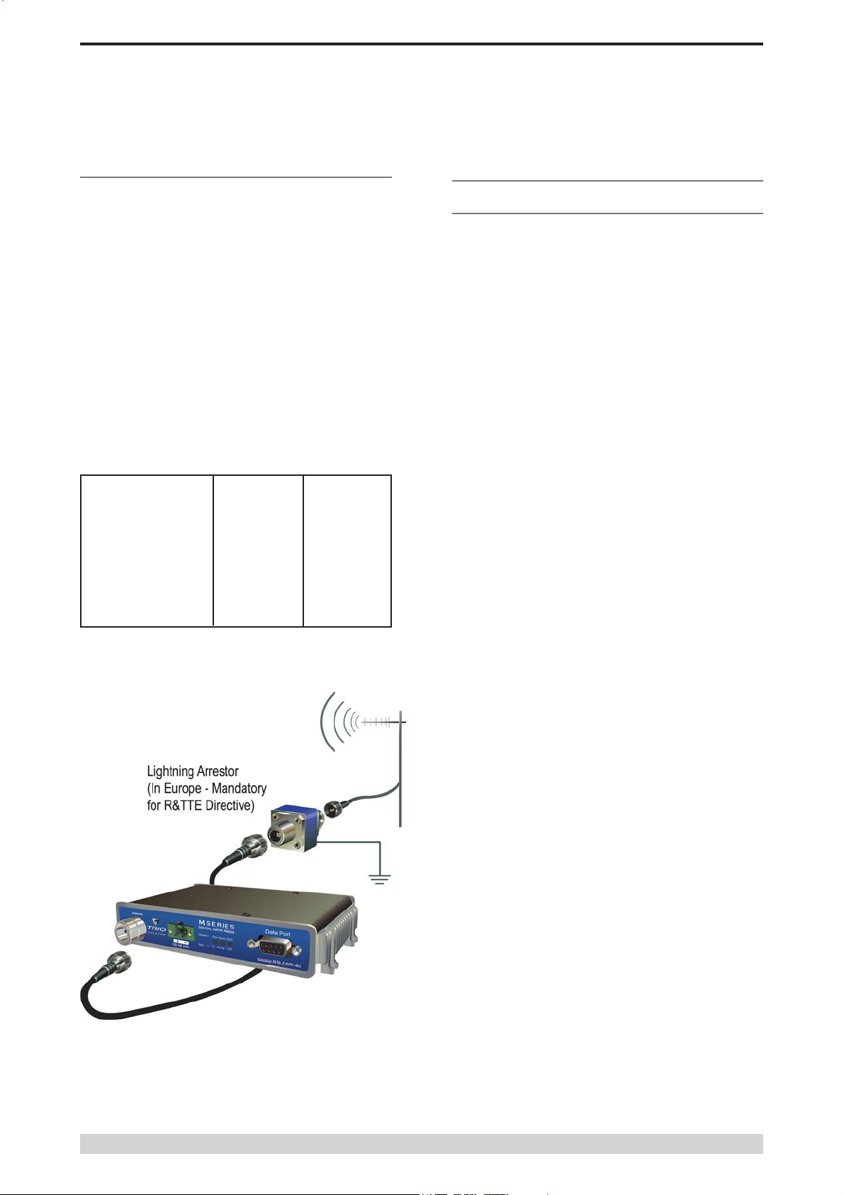
RF Feeders and Protection
The antenna is connected to the radio modem by way of an RF feeder.
In choosing the feeder type, one must compromise between the loss
caused by the feeder, and the cost, flexibility, and bulk of lower loss
feeders. To do this, it is often prudent to perform path analysis first, in
order to determine how much “spare” signal can be allowed to be lost
in the feeder. The feeder is also a critical part of the lightning protection
system.
All elevated antennas may be exposed to induced or direct lightning
strikes, and correct grounding of the feeder and mast are an essential
part of this process. Gas discharge lightning arresters should also be
fitted to all sites.
Note: All ETSI installations require the use of a lightning surge
arrestor in order to meet EN6095. See Part A - Preface for lightning
arrestor specifications.
Common Cable Types Loss per meter Loss per 10m
@ 450MHz @ 450MHz
RG58C/U 0.4426dB 4.4dB
RG213/U 0.1639dB 1.6dB
FSJ1-50 (¼” superflex) 0.1475dB 1.5dB
LDF4-50 (1/2” heliax) 0.0525dB 0.52dB
LDF5-50 (7/8” heliax) 0.0262dB 0.3dB
Data Connectivity
The V24 Standard
The M Series radio modems provide an asynchronous V24 compliant
RS232 port for connection to a serial data device.
There are two types of RS232 interfaces – DTE and DCE.
DTE stands for data terminal equipment and is generally applied to
any intelligent device that has a need to communicate to another
device via RS232. For example: P.C. Comm ports are always DTE,
as are most PLC and RTU serial ports.
DCE stands for data communication equipment and is generally
applied to a device used for sending data over some medium (wires,
radio, fibre etc), i.e. any MODEM.
The standard interface between a DTE and DCE device (using the
same connector type) is a straight through cable (i.e. each pin
connects to the same numbered corresponding pin at the other end of
the cable).
The “V24” definition originally specified the DB25 connector standard,
but this has been complicated by the emergence of the DB9 (pseudo)
standard for asynch devices, and this connector standard has different
pin assignments.
The wiring standard is “unbalanced”, and provides for three basic data
transfer wires (TXD, RXD, and SG – signal ground).
Page 16
© Copyright 2004 Trio DataCom Pty. Ltd.
 Loading...