

Schneider Electric Systems Canada ER450-XXF01 Installation guide

User Manual
E Series Data Radio
ER450 Remote Data Radio
EB450 Base Station
EH450 Hot Stand-by Base Station
www.trio.com.au
Issue 4: May 2003
E Series Data Radio – User Manual
!
Part A Preface
Warranty
All equipment supplied by Trio DataCom Pty . Ltd. is warranted against
faulty workmanship and parts for a period of twelve (12) months from
the date of delivery to the customer. During the warranty period Trio
DataCom Pty. Ltd. shall, at its option, repair or replace faulty parts or
equipment provided the fault has not been caused by misuse,
accident, deliberate damage, abnormal atmosphere, liquid immersion
or lightning discharge; or where attempts have been made by
unauthorised persons to repair or modify the equipment.
The warranty does not cover modifications to software. All equipment
for repair under warranty must be returned freight paid to Trio DataCom
Pty. Ltd. or to such other place as T rio DataCom Pty . Ltd. shall
nominate. Following repair or replacement the equipment shall be
returned to the customer freight forward. If it is not possible due to the
nature of the equipment for it to be returned to Trio DataCom Pty . Ltd.,
then such expenses as may be incurred by Trio DataCom Pty . Ltd. in
servicing the equipment in situ shall be chargeable to the customer.
When equipment for repair does not qualify for repair or replacement
under warranty, repairs shall be performed at the prevailing costs for
parts and labour. Under no circumstances shall Trio DataCom Pty .
Ltd.’s liability extend beyond the above nor shall Trio DataCom Pty .
Ltd., its principals, servants or agents be liable for the consequential
damages caused by the failure or malfunction of any equipment.
Part A - Preface
Warning :- RF Exposure
The radio equipment described in this user manual emits low level
radio frequency energy. The concentrated energy may pose a health
hazard depending on the type of antenna used. In the case of a nondirectional antenna do not allow people to come within 0.5 metres of
the antenna when the transmitter is operating. In the case of a
directional antenna do not allow people to come within 6 metres of the
antenna when the transmitter is operating.
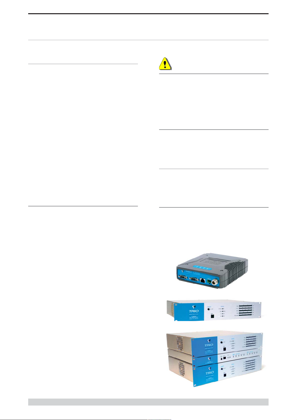
Related Products
ER450 Remote Data Radio
EB450 Base/Repeater Station
EH450 Hot Stand-by Base Station
Other Related Documentation
and Products
Quick Start Guide
TVIEW+ Management Suite
Digital Orderwire Voice Module (EDOVM)
Stream Router/Multiplexer (95MSR)
Important Notice
© Copyright 2002 Trio DataCom Pty. Ltd. All Rights Reserved
This manual covers the operation of the E Series of Digital Data
Radios. Specifications described are typical only and are subject to
normal manufacturing and service tolerances.
Trio DataCom Pty Ltd reserves the right to modify the equipment, its
specification or this manual without prior notice, in the interest of
improving performance, reliability or servicing. At the time of
publication all data is correct for the operation of the equipment at
the voltage and/or temperature referred to. Performance data
indicates typical values related to the particular product.
This manual is copyright by Trio DataCom Pty Ltd. All rights
reserved. No part of the documentation or the information supplied
may be divulged to any third party without the express written
permission of Trio DataCom Pty Ltd.
Same are proprietary to Trio DataCom Pty Ltd and are supplied for
the purposes referred to in the accompanying documentation and
must not be used for any other purpose. All such information
remains the property of Trio DataCom Pty Ltd and may not be
reproduced, copied, stored on or transferred to any other media or
used or distributed in any way save for the express purposes for
which it is supplied.
Products offered may contain software which is proprietary to Trio
DataCom Pty Ltd. However, the offer of supply of these products
and services does not include or infer any transfer of ownership of
such proprietary information and as such reproduction or reuse
without the express permission in writing from Trio DataCom Pty
Ltd is forbidden. Permission may be applied for by contacting Trio
DataCom Pty Ltd in writing.
Revision History
Issue 1 July 2002 Intitial Release
Issue 2 August 2002 Added EH450 Quick Start Section
and Specifications Section
Issue 3 November 2002 Major Edits to TVIEW and minor edits
to quick start sections.
Page 2
© Copyright 2002 Trio DataCom Pty . Ltd.

E Series Data Radio – User Manual
Contents
Contents
SECTION 1
Part A Preface 2
Warranty 2
Important Notice 2
Related Products 2
Other Related Documentation and Products 2
Revision History 2
Part B E Ser ies Over v iew 4
Definition of E Series Data Radio 4
E Series Product Range 4
E Series – Features and Benefits 4
Model Number Codes 6
Standard Accessories 7
Part C Applications 8
Generic Connectivity 8
Application Detail 8
Systems Architecture 9
Part D System Planning and Design 11
Understanding RF Path Requirements 11
Examples of Predictive Path Modelling 1 2
Selecting Antennas 1 4
Data Connectivity 1 5
Power Supply and Environmental Considerations 18
Physical Dimensions of the Remote Data Radio 1 9
Physical Dimensions of the Base Station 2 0
Physical Dimensions of the Hot Standby Base Station 2 1
SECTION 2
Part I TVIEW+ Management Suite Programmer 40
Introduction 40
Installation 4 0
TVIEW+ Front Panel 41
Programmer 41
Part J TVIEW+ Management Suite Remote Diagnostics & Network
Controller 53
Introduction 53
System Description 5 3
Operating Instructions 5 5
Interpreting Poll Results 6 6
Part K Appendices 67
Appendix A - Application and Technical Notes 67
Appendix B - Slip Protocol 67
Appendix C - Firmware Updates 6 8
Part L Specifications 69
Part M Support Options 70
Website Information 7 0
E-mail Technical Support 70
Telephone Technical Support 70
Contacting the Service Department 7 0
Part E Getting Started 22
ER450 Quick Start Guide 2 2
EB450 Quick Start Guide 2 8
EH450 Quick Start Guide 3 1
Part F - Operational Features 36
Multistream functionality (SID codes) 3 6
Collision Avoidance (digital and RFCD based) 3 6
Digipeater Operation 3 6
TVIEW+ Diagnostics 3 6
Part G Commissioning 37
Power-up 37
LED Indicators 3 7
Data Transfer Indications 37
Antenna Alignment and RSSI Testing 37
Link Establishment and BER Testing 3 7
VSWR Testing 37
Part H Maintenance 38
Routine Maintenance Considerations 3 8
© Copyright 2002 Trio DataCom Pty. Ltd.
Page 3
E Series Data Radio – User Manual
Part B E Series Overview
Part B E Series Overview
Definition of E Series Data Radio
The E Series is a range of wireless modems designed for the
transmission of data communications for SCADA, telemetry, and
any other information and control applications that utilise ASCII
messaging techniques. The E Series uses advanced “digital”
modulation and signal processing techniques to achieve
exceptionally high data throughput efficiency using traditional
licensed narrow band radio channels.
The products are available in many frequency band and regulatory
formats to suit spectrum bandplans in various continental regions.
The range is designed for both fixed point to point (PTP), and
multiple address (MAS) or point to multipoint (PMP) systems.
E Series Product Range
The E Series range consists of the basic half duplex “Remote”
radio modem, an extended feature full duplex Remote radio
modem, and ruggedised Base Station variants, including an
optional Hot Standby controller to control two base station units in
a redundant configuration.
Frequency band variants are indicated by the band prefix and
model numbering. (See Model Number Codes)
E Series Features and Benefits
Common Features and Benefits of the E
Series Data Radio
• Up to 19200bps over-air data rates using programmable
DSP based advanced modulation schemes
• Designed to various International regulatory requirements
including FCC, ETSI and ACA
• Superior receiver sensitivity
• Fast data turnaround time <10mS
• Flash upgrade-able firmware – insurance against obsolescence
• Multi-function bi-colour Tx/Rx data LEDS showing Port activity
(breakout box style), as well as LEDs indicating Tx, Rx, RF
Signal, Data Synchronisation and DC Power status of the
radio
• Rugged N type antenna connectors on all equipment
• High temperature transmitter foldback protection
• Two independent configurable data ports and separate system
port
• Higher port speeds to support increased air-rate (up to
76800bps on Port A and 38400bps on Port B)
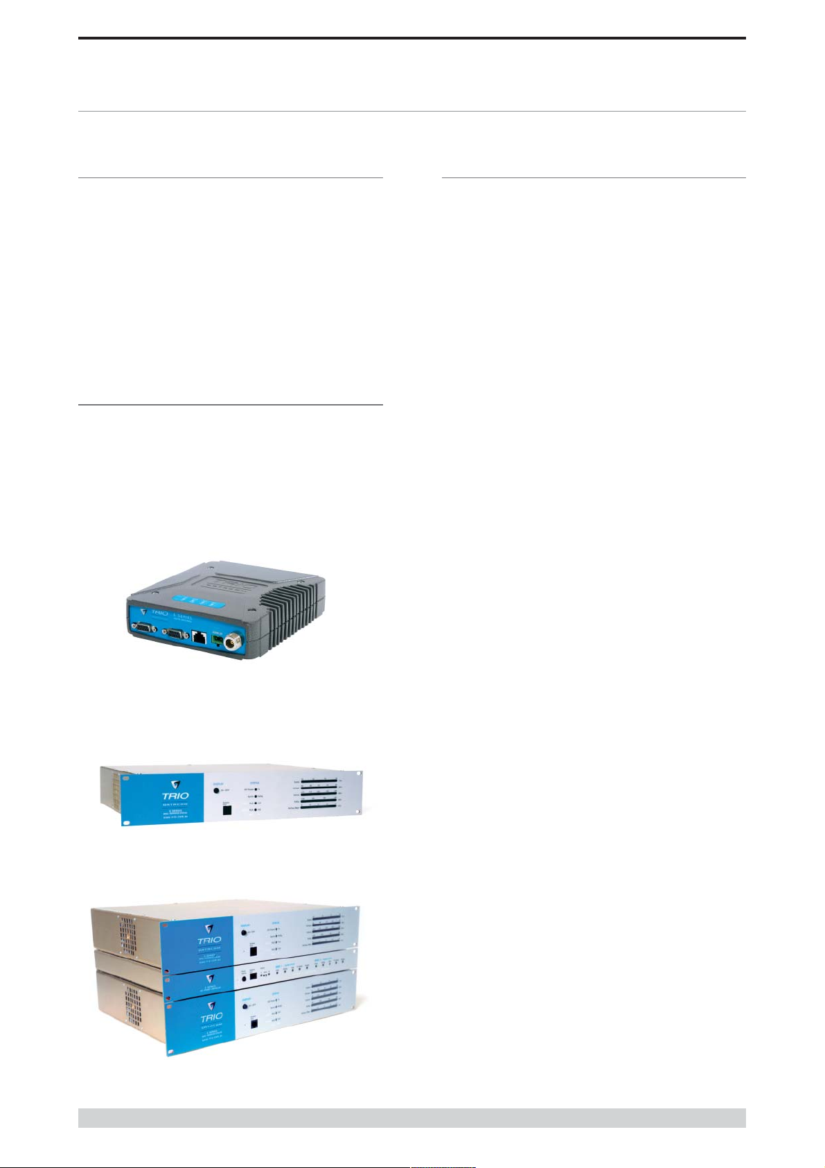
ER450 Remote Radio
EB450 Base / Repeater Station
• Independent system port for interruption free programming and
diagnostics (in addition to two (2) user ports)
• 9600bps in 12.5 kHz radio channels with ETSI specifications
• Remote over-the-air configuration of any radio from any location
• Multistream™ simultaneous data streams allows for multiple
vendor devices / protocols to be transported on the one radio
network
• Flexible data stream routing and steering providing optimum
radio channel efficiency – complex data radio systems can be
implemented with fewer radio channels
• The ability to duplicate data streams – that is, decode the same
off-air data to two separate ports.
• Multi-function radio capable of dropping off one stream to a port
and forward on or repeat (store and forward) the same or other
data.
• Stand-alone internal store and forward operation – buffered store
and forward operation even in the ER remote units
• Unique integrated C/DSMA collision avoidance technology
permits simultaneous polling and spontaneous reporting
operation in the same system
• Digital receiver frequency tracking for long term data reliability
Page 4
• Network wide non intrusive diagnostics which runs
simultaneously with the application
EH450 Hot Standby Base Station
© Copyright 2002 Trio DataCom Pty . Ltd.

E Series Data Radio – User Manual
Part B E Series Overview
• Network wide diagnostics interrogation which can be
performed from anywhere in the system including any remote
site
• Diagnostics will route its way to any remote or base / repeater
site regardless of how many base / repeater stations are
interconnected
• Full range of advanced features available within Network
Management and Remote Diagnostics package – BER testing,
trending, channel occupancy, client / server operation, etc.
• On board memory for improving user data latency – increased
user interface speeds
• Full CRC error checked data – no erroneous data due to
squelch tails or headers
• Radio utilises world standard HDLC as its transportation
protocol
• Various flow control and PTT control mechanisms
• Configurable backward compatibility with existing D Series
modulation scheme for use within existing networks
• Digital plug in order wire option for commissioning and
occasional voice communications without the need to inhibit
users application data
Features and Benefits of ER450 Remote
Data Radio
• Optional full duplex capable remote – separate Tx and Rx ports
for connection to an external duplexer
• New compact and rugged die cast case with inbuilt heatsink
• Low power consumption with various sleep modes
• Rugged N type antenna connectors
• In-line power supply fuses
• Data Port “breakout box” style flow LEDs for easier
troubleshooting
Features and Benefits of EB450 Standard
Base / Repeater Station
• Competitively priced high performance base
• Incorporates a rugged 5W power amplifier module
• External input for higher stability 10MHz reference – GPS
derived
Features and Benefits of EH450 Hot Standby
Base / Repeater Station
• Individual and identical base stations with separate control logic
changeover panel
• ALL modules are hot swapable without any user downtime
• Flexible antenna options – single, separate Tx & Rx, two Tx
and two Rx
• Increased sensitivity with receiver pre-amplifier
• Both on-line and off-line units monitored regardless of active
status
• External input for higher stability 10MHz reference – GPS
derived
© Copyright 2002 Trio DataCom Pty. Ltd.
Page 5
E Series Data Radio – User Manual
)
#
#
#
y
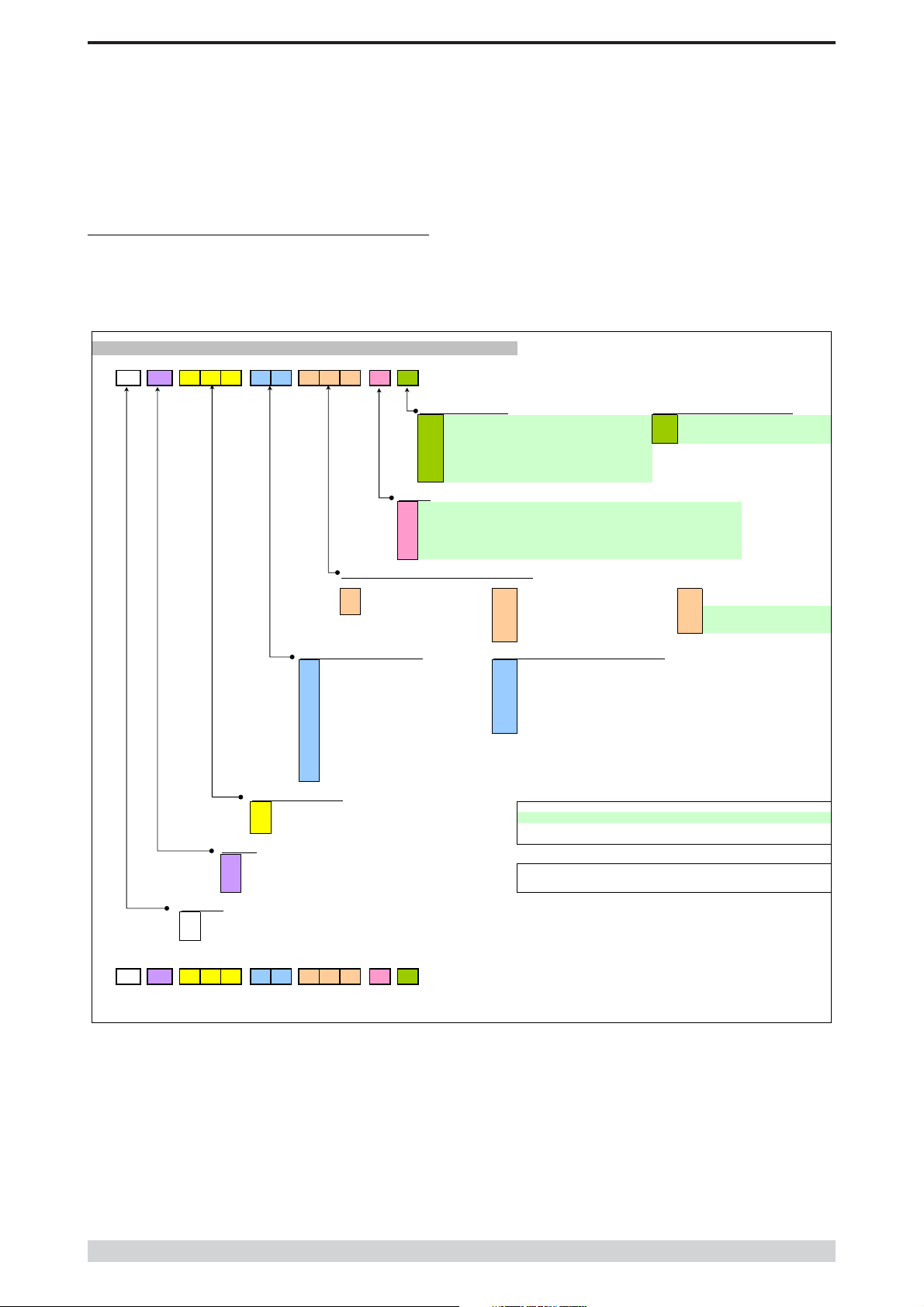
Model Number Codes
D, E & S Series Data Radios - Part Number Matrix = Tyxxx-aabbb-cd
T y xxx- aa bbb- cd
Options - Base Stations* Options - Remote Antenna Connector*
0 = No Options 0 = No Options (Standard)
= 450MHz Band Reject
1
= 450MHz Band Reject
2
= 450MHz Band Pass
3
= 900MHz Band Reject
4
= 900MHz Band Pass
5
= 900MHz Band Pass
6
Note: Specify Internally or Externally fitted. Externally fittered duplexes require feeder tails.
Options*
0 = No Options
D = Diagnostics - [DIAGS/D, DIAGS/DH, DIAGS/E or DIAGS/EH] (D & E Series Only)
H = Extended Temp Option [HITEMP]
N = Remote Fitted into NEMA Enclosure [NEMA 4/R]
F = Full Duplex Operation [ERFD450] (ER450 only)
X = Full Duplex Operation [ERFD450 & DIAGS/E] (ER450 only)
RF Channel Data Rate & Bandwidth (Internal Modem
D Series E Series
A01 = ACA 4800bps in 12.5kHz A01
A02 = ACA 9600bps in 25kHz A02
F01 = FCC 9600bps in 12.5kHz F01
Frequency (200 & 400 MHz range)
39 = 208 to 240MHz (Tx & Rx) 07 = (Tx) 847 to 857MHz (Rx) 923 to 933MHz (D Series only, 1W Full Duplex)
50 = 403 to 417MHz (Tx & Rx) 10 = (Tx) 848 to 858MHz (Rx) 920 to 934MHz
58 = (Tx) 406 to 421MHz (Rx) 415 to 430MHz 06 = (Tx) 923 to 933MHz (Rx) 847 to 857MHz (D Series only, 1W Full Duplex)
59 = (Tx) 415 to 430MHz (Rx) 406 to 421MHz 11 = (Tx) 920 to 934MHz (Rx) 848 to 858MHz
56 = 418 to 435MHz (Tx & Rx) 12 = 855 to 860MHz (Tx & Rx)
57 = 428 to 443MHz (Tx & Rx) 14 = (Tx) 925 to 943MHz (Rx) 906 to 924MHz
55 = 436 to 450MHz (Tx & Rx) 15 = (Tx) 904 to 922MHz (Rx) 925 to 943MHz
51 = 450 to 465MHz (Tx & Rx) 16 = 924 to 944MHz (Tx & Rx)
52 = 465 to 480MHz (Tx & Rx)
53 = 480 to 494MHz (Tx & Rx) Note: Other frequency bands available upon request.
54 = 505 to 518MHz (Tx & Rx)
27 = (Tx) 511 to 515MHz (Rx) 501 to 505MHz
48 = 395 to 406MHz (Tx & Rx)
Generic Frequency Band
200 = 208 to 245MHz (D & S Series only) NOTES:
450 = 400 to 518MHz (E & S Series only) * Additional charges apply. Must be ordered seperately. Please refer to price list.
900 = 800 to 960MHz (D & S Series only)
Unit Type
R = Remote Station
B = Base / Repeater Station Standards: ACA - Australian Communications Authority
S = Standard Base / Repeater Station (D Series Only) FCC - Federal Communications Commission
H = Hot Standby Base / Repeater (D & E Series Only) ETSI - European Telcommunication Standards Institute
Model Type
D = D Series Family
= E Series Family
E
= S Series Famil
S
Example:
E R 450- 51 A02- D0
The above example specifies: E Series, Remote Radio, generic 450MHz band, with a specific frequency of 450MHz to 465MHz,
a 96/19.2kbps modem, with a bandwidth of 25kHz, diagnostics and standard N type connector.
F02 = FCC 19k2bps in 25kHz 242 = 2400bps in 25kHz [24SR]*
E01 = ETSI 9600bps in 12.5kHz 482 = 4800bps in 25kHz [48SR]*
E02 = ETSI 19k2bps in 25kHz
Frequency (900 MHz range) (D & S Series Only)
[DUPLX450BR]
(<9MHz split)[DUPLX450BR/5]
[DUPLX450BP]
[DUPLX900BR]
[DUPLX900BP]
(76MHz split)[DUPLX852/930]
/ 9600bps in 12.5Hz
= ACA 4800
= ACA 9600
= FCC 9600
#
Items in [ ] parenthesis refer to actual Trio part numbers
/ 19k2bps in 25kHz
/ 9600bps in 12.5kHz
Provides compatibility with D Series radio
N = N Connector (D Series only)
S = SMA Connector (SR450 only)
S Series
001 = 12.5kHz (No Modem Fitted)
002 = 25kHz (No Modem Fitted)
241 = 2400bps in 12.5kHz [24SR]*
Version: 11/02
Page 6
© Copyright 2002 Trio DataCom Pty . Ltd.

E Series Data Radio – User Manual
Standard Accessories
Part B E Series Overview
Part Number Description
Duplexers
DUPLX450BR Duplexer BAND REJECT 400-520 MHz for use
with Base / Repeater / Links. For Tx / Rx
frequency splits >9MHz. (Fitted Externally for a
Link, Intenally or Externally for Base / Repeater)
DUPLX450BR/5 Duplexer BAND REJECT 400-520 MHz for use
with Base / Repeater / Links. For Tx / Rx
frequency splits <9MHz. (Fitted Externally for a
Link, Intenally or Externally for Base / Repeater)
DUPLX450BP Duplexer PSEUDO BAND PASS Cavity 400-
520 MHz for External use with Base / Repeater
/ Links.
Notes:
1. Frequencies must be specified at time of order.
2. Interconnecting (Feeder Tail) cables must be ordered
separately for Externally fitted Duplexers.
Antennas
ANT450/9A Antenna Yagi 6 Element 9dBd Aluminium 400-
520 MHz c/w mtg clamps
ANT450/9S Antenna Yagi 6 Element 9dBd S/Steel 400-520
MHz c/w mtg clamps
ANT450/13A Antenna Yagi15 Element 13dBd Aluminium 400-
520 MHz c/w mtg clamps.
ANT450/13S Antenna Yagi 15 Element 13dBd S/Steel 400-
520 MHz c/w mtg clamps.
ANTOMNI/4 Antenna Omni-directional Unity Gain Side
Mount Dipole 400-520 MHz c/w galv. clamp
ANT450/D Antenna Omni-directional Unity Gain Ground
Independant Dipole 400-520 MHz c/w 3m
cable, mounting bracket & BNC connector
ANT450/6OM Antenna Omni-directional 6dBd 400-520 MHz
c/w mtg clamps
ANT450/9OM Antenna Omni-directional 9dBd 400-520 MHz c/
w mtg clamps
Note:
1. Frequencies must be specified at time of order.
Power Supplies
PS13V82A Power Supply 13.8V 2A 240VAC
PS13V810A Power Supply Switch Mode 240VAC 13.8V 10A
for Base Stations – Battery Charge Capability
Part Number Description
RF Cables and Accessories
NM/NM/TL Feeder Tail - N Male to N Type Male 50cm fully
sweep tested
NM/NM/TLL Feeder Tail - N Male to N Type Male 1 metre
fully sweep tested
RFCAB5M 5.0m RG-58 type Antenna Feeder Cable
terminated with N type Male Connectors
RFCAB5M2 5.0m RG-213 type Antenna Feeder Cable
terminated with N type Male Connectors
RFCAB10M 10.0m RG-213 type Antenna Feeder Cable
terminated with N type Male Connectors
RFCAB20M 20.0m RG-213 type Antenna Feeder Cable
terminated with N type Male Connectors
RFCAB20M4 20.0m LDF4-50 type (1/2" foam dialectric)
Antenna Feeder Cable terminated with N type
Male Connectors
LGHTARRST Lightning Surge Arrestor In-line N Female to N
Female
Multiplexers
95MSR/6 Multiplexer/Stream Router – 6 Port with RS-232
I/faces and Manual
95MSR/9 Multiplexer/Stream Router – 9 Port with RS-232
I/faces and Manual
Network Management Diagnostics
DIAGS/E Network Management and Remote Diagnostics
Facilities per Radio – E Series
DIAGS/EH Network Management and Remote Diagnostics
Facilities – E Series for EH450
Software
TVIEW+ Configuration, Network Management and
Remote Diagnostics Software
Other
NEMA 4 /R Stainless Steel Enclosure for Remote Site
Equipment.Size 600mm (h) x 600mm (d) x
580mm (w) – Room for Third Party RTU / PLC
equip. (Approx. 400(h) x 600(d) x 580mm(w)
HITEMP Extended Temperature Option for S, D and E
Series Radios -30 to +70C
EDOVM Digital Order Wire Voice Module
ERFD450 ER450…. Conversion to Full Duplex Operation
(N Type – Tx Port, SMA - Type Rx Port)
Note: Requires external duplexer
ERFDTRAY 19" Rack Tray for Mounting of ER450 Full Duplex
Radio and External Band Reject Duplexer
© Copyright 2002 Trio DataCom Pty. Ltd.
Page 7

E Series Data Radio – User Manual
Part C Applications
Part C Applications
Generic Connectivity
The E Series has been designed for SCADA and telemetry
applications, and any other applications that use an ASCII
communications protocol, and which connect physically using the
RS232 interface standard (although converters can be used to
adapt other interfaces such as RS422/485, RS530/V35, G703 etc).
Any protocol that can be displayed using a PC based terminal
program operating via a serial comm port is suitable for
transmission by the E Series radio modems.
An ASCII protocol is any that consists of message strings formed
from ASCII characters, that being defined as a 10 or 11 bit block
including start and stop bits, 7 or 8 data bits and optional parity
bit(s). Port set-up dialog that includes the expressions “N,8,1”, or
E,7,2” or similar indicate an ASCII protocol.
Most of the dominant telemetry industry suppliers utilise proprietary
ASCII protocols, and also common “open standard” industry
protocols such as DNP3, MODBUS, TCP/IP, and PPP. These are
all ASCII. based protocols.
Industries and Applications
The E Series products are widely used in point-to-point and pointto-multipoint (multiple access) applications for remote
interconnection of PLC’s, RTU’s, dataloggers, and other data
monitoring and control devices including specialist utility devices
(such as powerline ACR’s). In addition, other applications such as
area wide security and alarm systems, public information systems
(traffic flow and public signage systems) and environmental
monitoring systems.
Application Detail
SCADA Systems
This is where one or more centralised control sites are used to
monitor and control remote field devices over wide areas.
Examples include regional utilities monitoring and controlling
networks over entire shires or a greater city metropolis’. Industry
sectors include energy utilities (gas and electricity distribution),
water and sewerage utilities, and catchment and environment
groups (rivers, dams, and catchment management authorities).
Telemetry Systems
Dedicated telemetry control systems interconnecting sequential
devices where cabling is not practical or distances are
considerable.
Examples include ore conveyor or slurry pipeline systems, simple
water systems (pump and reservoir interlinking), broadcast industry
(linking studio to transmitter) etc.
Information Systems
Public Information systems such as freeway vehicle flow and travel
time monitoring, and feedback signage, parking signage systems,
meteorological stations etc.
Page 8
© Copyright 2002 Trio DataCom Pty . Ltd.
E Series Data Radio – User Manual
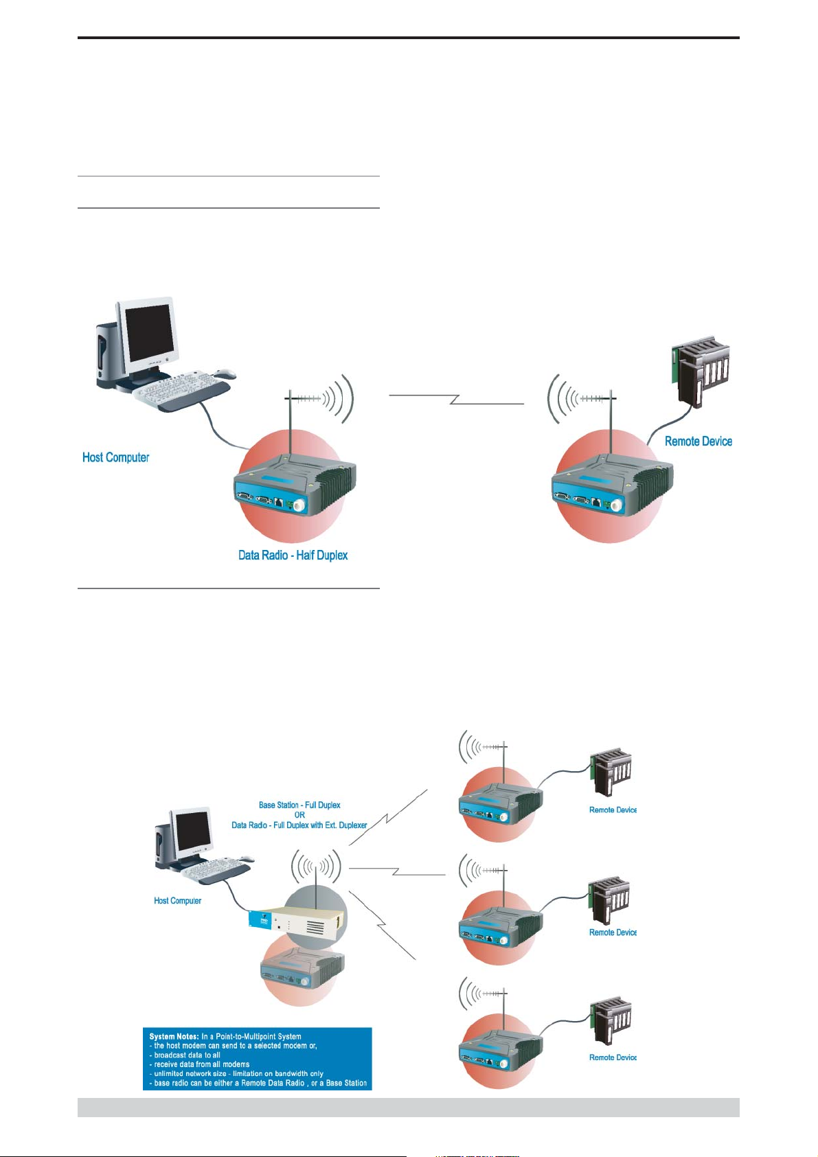
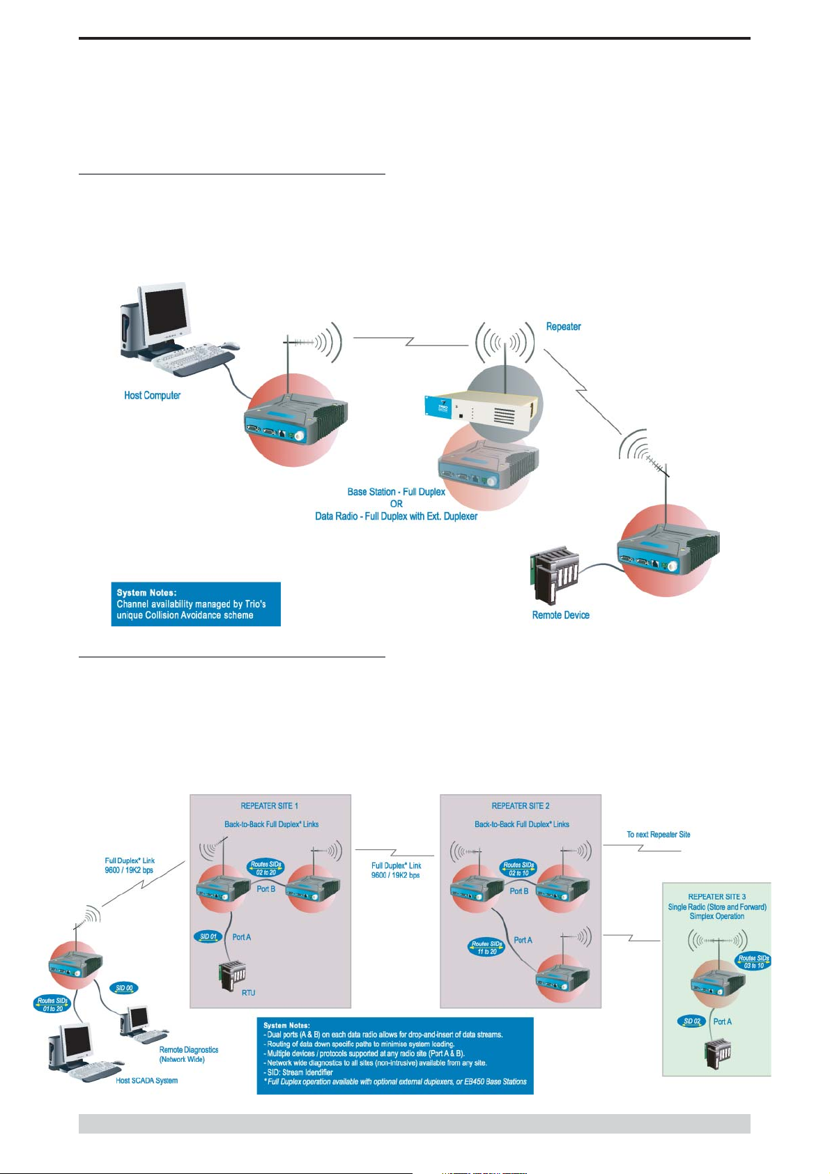
Systems Architecture
Point-to-Point
This simple system architecture provides a virtual connection
between the two points, similar to a cable. Dependant of the
hardware chosen, it is possible to provide a full duplex connection
(i.e. data transfer in both directions simultaneously) if required.
Part C Applications
Point-to-Multipoint Systems
In a multiple access radio system, messages can be broadcast
from one (master) site to all others, using a half duplex radio
system, or from any site to all others, using a simplex radio
channel.
Half duplex systems often utilise a full duplex master, to make the
system simpler, and to operate faster.
In either case, it will be necessary for the application to support an
addressing system, since the master needs to be able to select
which remote device it wishes to communicate to. Normally, the
radio system is allowed to operate “transparently”, allowing the
application’s protocol to provide the addressing, and thus control
the traffic. Where the application layer does not provide the
addressing, the E Series can provide it using SID codes™. (See
Part F - Operational Features)
© Copyright 2002 Trio DataCom Pty. Ltd.
Page 9
E Series Data Radio – User Manual
Digipeater Systems
Part C Applications
This configuration is used where all sites are required to
communicate via a repeater site. A repeater site is used because it
has a position and/or height advantage and thus provides superior
or extended RF coverage. The radio modem at the repeater does
not have to be physically connected to the application’s master
site. Information from the application’s master is transmitted to the
repeater via radio, and the repeater then relays this information to
the other field sites. In this scenario, the repeater is the master
from an RF point of view, and the application master is effectively a
“remote” from an RF point of view, even though it is controlling the
data transfer on the system.
Store and Forward Systems
Store and forward is used as a way of extending RF coverage by
repeating data messages from one site to another.
This can be done globally using the inbuilt data repeating functions, or
selectively using intelligent address based routing features available in
some PLC/RTU protocols.
In this case it is necessary for all units on the system to operate in
half duplex mode (only key-up when transmitting data), so that
each site is free to hear received signals from more than one
source.
Page 10
© Copyright 2002 Trio DataCom Pty . Ltd.

E Series Data Radio – User Manual
Part D System Planning and Design
Part D System Planning and Design
Understanding RF Path
Requirements
A radio modem needs a minimum amount of received RF signal to
operate reliably and provide adequate data throughput.
In most cases, spectrum regulatory authorities will also define or
limit the amount of signal that can be transmitted, and the
transmitted power will decay with distance and other factors, as it
moves away from the transmitting antenna.
It follows, therefore, that for a given transmission level, there will be
a finite distance at which a receiver can operate reliably with
respect to the transmitter.
Apart from signal loss due to distance, other factors that will decay
a signal include obstructions (hills, buildings, foliage), horizon
(effectively the bulge between two points on the earth), and (to a
minimal extent at UHF frequencies) factors such as fog, heavy
rain-bursts, dust storms, etc.
In order to ascertain the available RF coverage from a transmitting
station, it will be necessary to consider these factors. This can be
done in a number of ways, including
(a) using basic formulas to calculate the theoretically
available signal - allowing only for free space loss due to
distance,
(b) using sophisticated software to build earth terrain models
and apply other correction factors such as earth curvature
and the effects of obstructions, and
(c) by actual field strength testing.
It is good design practice to consider the results of at least two of
these models to design a radio path.
© Copyright 2002 Trio DataCom Pty. Ltd.
Page 11
E Series Data Radio – User Manual
l3
te
te
)
3
7
S
S
E
E
th
180.10
0.10
L
)
40.00
5.00
i)
5
5
)
6.00
9.00
e
0
0
)
40.00
5.00
)
9
9
)
2.72
0.34
)
0
0
z)
0
)
4
)
112.78
)
1
)
117.25
117.25
el
0
0
s)
5.00
1.00
)
9
0
E
s)
1
3
E
)
8.27
6.66
)
1
6
)
0
0
)
9.70
21.70
)
5
6
)
4
3
)
22.75
24.74
)
0
5
l3
te
te
)
9
7
S
S
E
E
th
297.05
117.21
L
)
40.00
5.00
i)
5
5
)
6.00
9.00
e
0
0
)
40.00
5.00
)
9
9
)
2.72
0.34
)
0
0
z)
0
)
3
)
115.99
)
0
)
103.75
103.75
el
0
0
s)
5.00
1.00
)
9
0
E
s)
1
3
E
)
8.27
6.66
)
1
6
)
0
0
)
45.93
102.70
)
5
6
)
4
2
)
36.25
38.24
)
6
5
Part D System Planning and Design
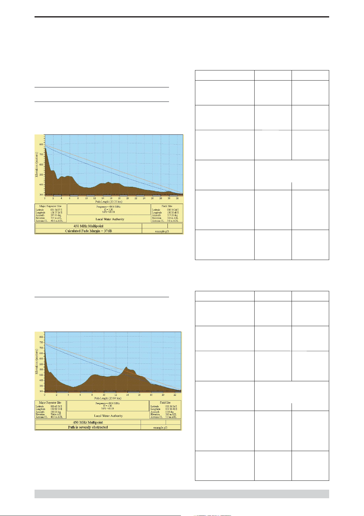
Examples of Predictive Path
Modelling
Clear line of site
Radio path with good signal levels, attenuated only by free space
loss.
goodpath.p
Elevation (m
Latitude 031 04 37.49
Longitude 150 57 26.34
Azimu
Antenna Type ANT450/6OM
Antenna Height ( m
Antenna Gain (dB
Antenna Gain (dBd
TX Line Typ
TX Line Length (m
TX Line Unit Loss (dB/100 m
TX Line Loss (dB
Connector Loss (dB
Frequency (MH
Path Length (km
Free Space Loss (dB
Diffraction Loss (dB
Net Path Loss (dB
Radio Type Mod
TX Power (watt
TX Power (dBW
ffective Radiated Power (watt
ffective Radiated Power (dBW
RX Sensitivity Level (uv
RX Sensitivity Level (dBW
RX Signal (uv
RX Signal (dBW
RX Field Strength (uv/m
Fade Margin (dB
Raleigh Service Probability (%
Major Repeater Si
756.6
8.1
LDF4-5
6.7
2.0
EB45
6.9
6.7
0.7
-140.0
-103.7
453.1
99.97
450.0
33.3
0.0
Field Si
309.6
030 56 24.00
150 38 48.00
ANT450/9A
11.1
LDF4-5
ER45
-135.0
-96.7
545.4
99.98
6.7
2.0
0.0
4.6
1.2
Obstructed Radio Path
This path has an obstruction that will seriously degrade the signal
arriving at the field site.
obstpath.p
Elevation (m
Latitude 030 43 55.92
Longitude 150 38 49.51
Azimu
Antenna Type ANT450/6OM
Antenna Height ( m
Antenna Gain (dB
Antenna Gain (dBd
TX Line Typ
TX Line Length (m
TX Line Unit Loss (dB/100 m
TX Line Loss (dB
Connector Loss (dB
Frequency (MH
Path Length (km
Free Space Loss (dB
Diffraction Loss (dB
Net Path Loss (dB
Radio Type Mod
TX Power (watt
TX Power (dBW
ffective Radiated Power (watt
ffective Radiated Power (dBW
RX Sensitivity Level (uv
RX Sensitivity Level (dBW
RX Signal (uv
RX Signal (dBW
RX Field Strength (uv/m
Fade Margin (dB
Raleigh Service Probability (%
Major Repeater Si
703.8
8.1
LDF4-5
6.7
2.0
EB45
6.9
6.7
0.7
-140.0
-117.2
95.7
99.47
450.0
23.0
16.7
Field Si
309.6
030 56 24.00
150 38 48.00
ANT450/9A
11.1
LDF4-5
ER45
-135.0
-110.2
115.2
99.66
6.7
2.0
0.0
4.6
1.2
Page 12
© Copyright 2002 Trio DataCom Pty . Ltd.
E Series Data Radio – User Manual
3
te
te
)
6
8
S
E
th
2
7
e
L
)
0
0
i)
5
5
)
6.00
9.00
e
0
0
)
0
0
9
9
)
2.72
0.34
)
0
0
z)
0
)
6
)
5
)
4
)
133.55
133.55
el
0
0
s)
0
0
)
9
0
E
s)
2
4
E
)
7
6
)
0.71
1.26
)
0
0
)
9
2
)
5
6
)
14.65
17.64
)
5
4
)
79.735
86.656
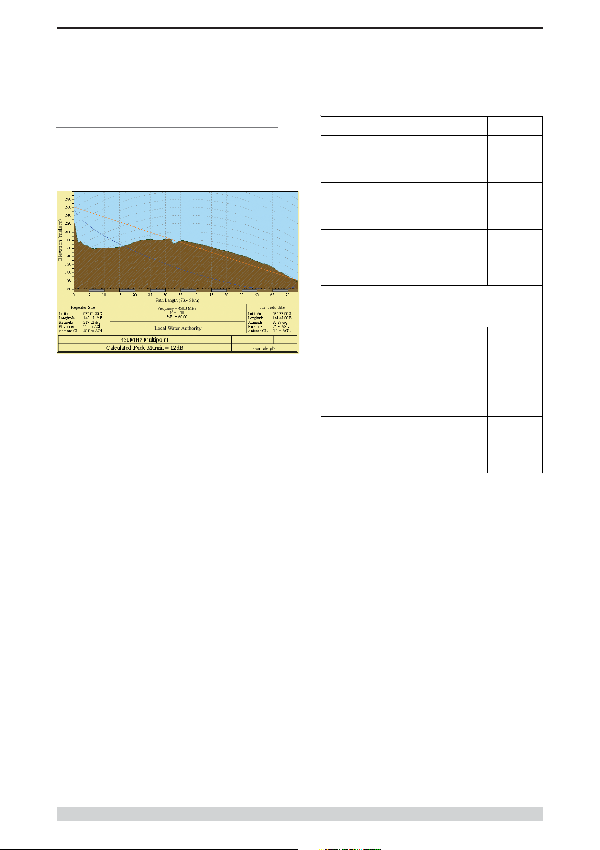
Part D System Planning and Design
Effect of Earth Curvature on Long Paths
This path requires greater mast height to offset the earth curvature
experienced at such a distance (73km).
longpath.pl
Elevation (m
Latitude 032 01 21.63 S 032 33 00.00
Longitude 142 15 19.26 E 141 47 00.00
Azimu
Antenna Typ
Antenna Height (m
Antenna Gain (dB
Antenna Gain (dBd
TX Line Typ
TX Line Length (m
TX Line Lo ss (dB
Connector Loss (dB
Frequency (MH
Path Length (km
Free Space Loss (dB
Diffraction Loss (dB
Net Path Loss (dB
Radio Type Mod
TX Power (watt
TX Power (dBW
ffective Radiated Power (watt
ffective Radiated Power (dBW
RX Sensitivity Level (uv
RX Sensitivity Level (dBW
Repeater Si
221.2
217.1
ANT450/6OM ANT450/9A
40.0
LDF4-5
40.0
EB45
-140.0
8.1
6.7
2.0
5.0
6.9
6.7
8.2
Far Field Si
75.5
37.3
5.0
11.1
LDF4-5
5.0
6.7
2.0
450.0
73.4
122.8
22.9
ER45
1.0
0.0
4.6
6.6
-135.0
RX Signal (uv
RX Signal (dBW
RX Field Strength (uv/m
Fade Margin (dB
Raleigh Service Probability (%
1.4
-133.5
6.4
3.3
-126.5
8.4
© Copyright 2002 Trio DataCom Pty. Ltd.
Page 13
E Series Data Radio – User Manual
Part D System Planning and Design
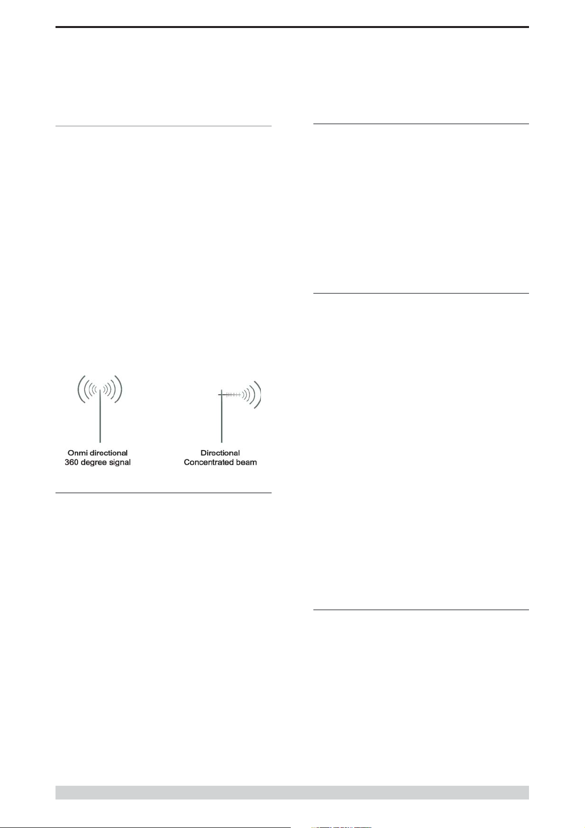
Selecting Antennas
There are basically two types of antennas – omni directional, and
directional.
Omni directional antennas are designed to radiate signal in a 360
degrees segment around the antenna. Basic short range antennas
such as folded dipoles and ground independent whips are used to
radiate the signal in a “ball” shaped pattern. High gain omni
antennas such as the “co-linear” compress the sphere of energy
into the horizontal plane, providing a relatively flat “disc” shaped
pattern which goes further because all of the energy is radiated in
the horizontal plane.
Directional antennas are designed to concentrate the signal into
“beam” of energy for transmission in a single direction (ie for pointto-point or remote to base applications).
Beamwidths vary according to the antenna type, and so can be
selected to suit design requirements. The most common UHF
directional antenna is the yagi, which offers useable beam widths
of 30-50 degrees. Even higher “gain” is available using parabolic
“dish” type antennas such as gridpacks.
Antenna Gain
By compressing the transmission energy into a disc or beam, the
antenna provides more energy (a stronger signal) in that direction,
and thus is said to have a performance “gain” over a basic omni
antenna. Gain is usually expressed in dBd, which is referenced to
a standard folded dipole. Gain can also be expressed in dBi, which
is referenced to a theoretical “isotropic” radiator. Either way, if you
intend to send and receive signals from a single direction, there is
advantage in using a directional antenna - both due to the
increased signal in the wanted direction, and the relatively
decreased signal in the unwanted direction (i.e. “interference
rejection” properties).
Tuning the Antenna
Many antennas are manufactured for use over a wide frequency
range. Typical fixed use antennas such as folded dipoles and yagis
are generally supplied with the quoted gain available over the
entire specified band range, and do not require tuning. Co-linear
antennas are normally built to a specific frequency specified when
ordering.
With mobile “whip” type antennas, it is sometimes necessary to
“tune” the antenna for the best performance on the required
frequency. This is usually done by trimming an antenna element
whilst measuring VSWR, or simply trimming to a manufacturer
supplied chart showing length vs frequency. These antennas would
normally be supplied with the tuning information provided.
Antenna Placement
When mounting the antenna, it is necessary to consider the
following criteria:
The mounting structure will need to be solid enough to withstand
additional loading on the antenna mount due to extreme wind, ice
or snow (and in some cases large birds).
For omni directional antennas, it is necessary to consider the effect
of the mounting structure (tower mast or building) on the radiation
pattern. Close in structures, particularly steel structures, can alter
the radiation pattern of the antenna. Where possible, omni
antennas should always be mounted on the top of the mast or pole
to minimise this effect. If this is not possible, mount the antenna on
a horizontal outrigger to get it at least 1-2m away from the
structure. When mounting on buildings, a small mast or pole (2-4m)
can significantly improve the radiation pattern by providing
clearance from the building structure.
For directional antennas, it is generally only necessary to consider
the structure in relation to the forward radiation pattern of the
antenna, unless the structure is metallic, and of a solid nature. In
this case it is also prudent to position the antenna as far away from
the structure as is practical. With directional antennas, it is also
necessary to ensure that the antenna cannot move in such a way
that the directional beamwidth will be affected. For long yagi
antennas, it is often necessary to instal a fibreglass strut to
stablilise the antenna under windy conditions.
Alignment of Directional Antennas
This is generally performed by altering the alignment of the
antenna whilst measuring the received signal strength. If the signal
is weak, it may be necessary to pre-align the antenna using a
compass, GPS, or visual or map guidance in order to “find” the
wanted signal. Yagi antennas have a number of lower gain “lobes”
centred around the primary lobe. When aligning for best signal
strength, it is important to scan the antenna through at least 90
degrees, to ensure that the centre (strongest) lobe is identified.
Page 14
When aligning a directional antenna, avoid placing your hands or
body in the vicinity of the radiating element or the forward beam
pattern, as this will affect the performance of the antenna.
© Copyright 2002 Trio DataCom Pty . Ltd.
E Series Data Radio – User Manual
Part D System Planning and Design
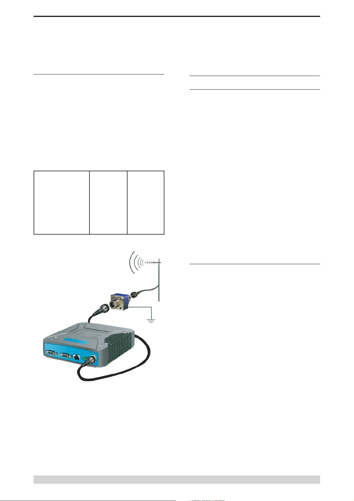
RF Feeders and Protection
The antenna is connected to the radio modem by way of an RF
feeder. In choosing the feeder type, one must compromise
between the loss caused by the feeder, and the cost, flexibility, and
bulk of lower loss feeders. To do this, it is often prudent to perform
path analysis first, in order to determine how much “spare” signal
can be allowed to be lost in the feeder. The feeder is also a critical
part of the lightning protection system.
All elevated antennas may be exposed to induced or direct
lightning strikes, and correct grounding of the feeder and mast are
an essential part of this process. Gas discharge lightning arresters
should also be fitted to any site that stands elevated or alone,
particularly in rural areas.
Common Cable Types Loss per meter Loss per 10m
@ 450MHz @ 450MHz
RG58C/U 0.4426dB 4.4dB
RG213/U 0.1639dB 1.6dB
FSJ1-50 (¼” superflex) 0.1475dB 1.5dB
LDF4-50 (1/2” heliax) 0.0525dB 0.52dB
LDF5-50 (7/8” heliax) 0.0262dB 0.3dB
Data Connectivity
The V24 Standard
The E Series radio modems provide two asynchronous V24
compliant RS232 ports for connection to serial data devices.
There are two types of RS232 interfaces – DTE and DCE.
DTE stands for data terminal equipment and is generally applied to
any intelligent device that has a need to communicate to another
device via RS232. For example: P.C. Comm ports are always DTE,
as are most PLC and RTU serial ports.
DCE stands for data communication equipment and is generally
applied to a device used for sending data over some medium
(wires, radio, fibre etc), i.e. any MODEM.
The standard interface between a DTE and DCE device (using the
same connector type) is a straight through cable (ie each pin
connects to the same numbered corresponding pin at the other end
of the cable).
The “V24” definition originally specified the DB25 connector
standard, but this has been complicated by the emergence of the
DB9 (pseudo) standard for asynch devices, and this connector
standard has different pin assignments.
The wiring standard is “unbalanced”, and provides for three basic
data transfer wires (TXD, RXD, and SG – signal ground).
Hardware Handshaking
Hardware handshake lines are also employed to provide flow
control, however (in the telemetry industry) many devices do not
always support all (or any) flow control lines.
For this reason, the E Series modems can be configured for full
hardware flow control, or no flow control at all (simple 3 wire
interface).
Note: that when connecting devices together with differing
handshake implementations, it is sometimes necessary to “loop”
handshake pins in order to fool the devices handshaking
requirements.
In telemetry applications (particularly where port speeds can be set
to the same rate as the radio systems over-air rate) then flow
control, and therefore handshaking, is usually NOT required. It
follows that any devices that CAN be configured for “no flow
control” should be used in this mode to simplify cabling
requirements.
Handshaking lines can generally be looped as follows:
DTE (terminal) – loop RTS to CTS, and DTR to DSR and DCE.
DCE (modem) - loop DSR to DTR and RTS (note-not required for
E Series modem when set for no handshaking).
© Copyright 2002 Trio DataCom Pty. Ltd.
Page 15
 Loading...