

Schneider Electric Systems Canada ER450-XXF01, EB450-XXF01 Users Manual
E Series Data Radio User Manual
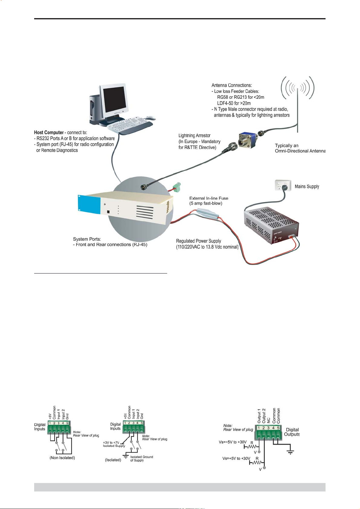
Typical Radio Setup
Part E Getting Started - EB450
Digital Inputs and Outputs
The EB450 provides a facility for two channels of digital user inputs
and outputs (Digital User I/O). Information on how to control and
monitor this I/O using TVIEW+ Diagnostics can be found in Part J TVIEW+ Management Suite - Remote Diagnostics & Network
Controller.
All user I/O is optocoupled for isolation between the EB450 and uses
equipment. When using the I/O facility the I/O electrical characteristics
and ratings must be observed. Failure to observe these ratings may
result in equipment damage.
Inputs
Two User Inputs are available. They have identical interface
characteristics. Each input has an internal resistance of 470 Ohms.
Some form of switching contact (ie: switch, relay) is normally used to
change the state of the input. Both an isolated and non-isolated input
configuration is possible.
TVIEW+ Diagnostics will recognise an input as being ON when the
switch is closed. If the switch is open (or not connected) TVIEW+
diagnostics will recognise the inputs as being OFF.
Outputs
Two User Outputs (Open Collector) are available. They have identical
interface characteristics. The maximum current allowed through each
output is 20ma. External resistors must be used keep the current
below this value.
Each output has an internal resistance of 100 Ohms.Ohms law can be
used to calculate the resistance required for a specific voltage (keeping
the current below 20mA). Nominally 1k Ohm is used for a +13v8
supply and 330 Ohms for a +5v supply.
When the OUTPUT is OFF, V = Vs. No current will flow when output
is off.
When the OUTPUT is ON, V = nominally 2.3 volts . Current is set
by resistor.
© Copyright 2004 Trio DataCom Pty. Ltd.
Is
Page 31
E Series Data Radio User Manual
Part E Getting Started - EB450
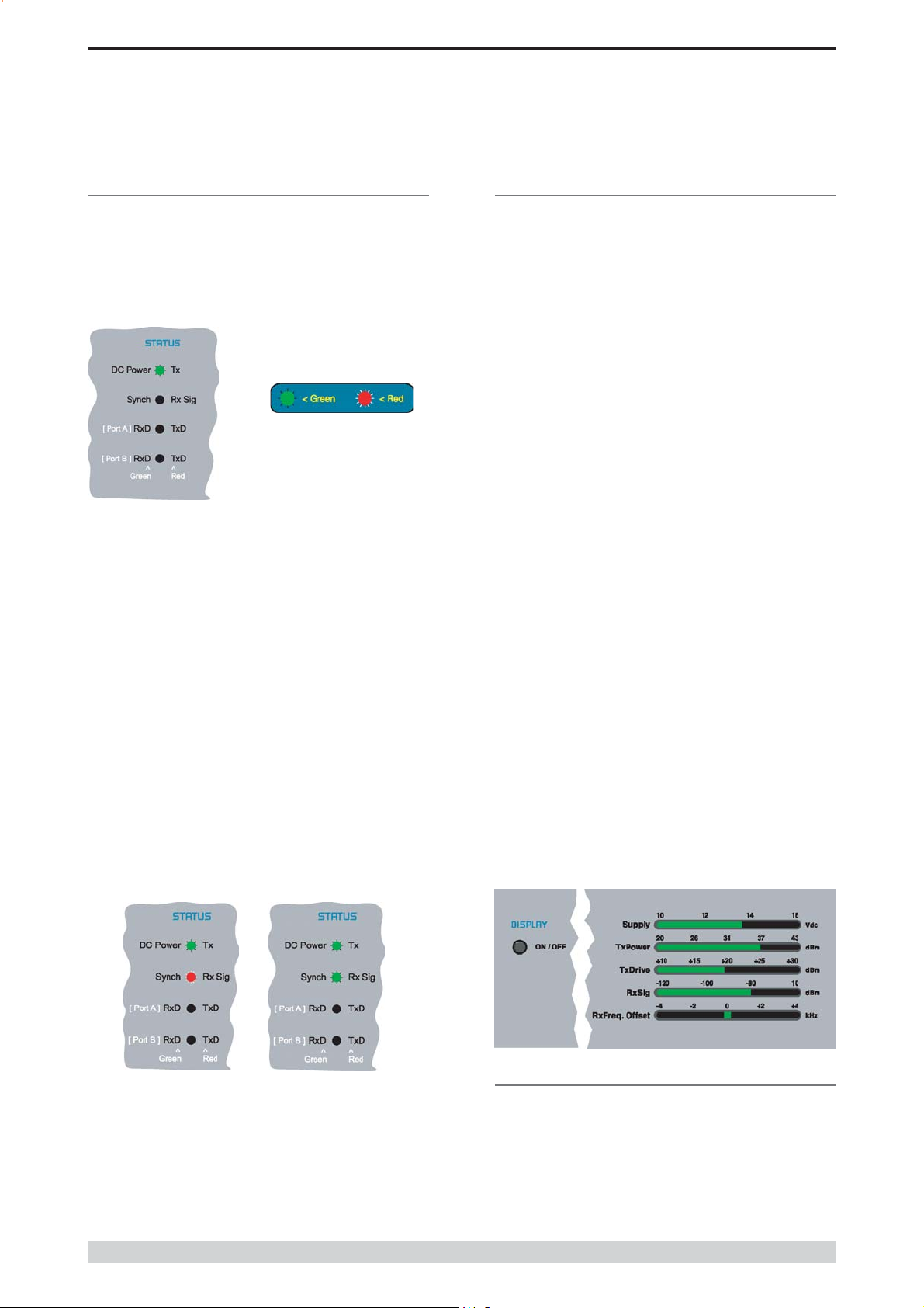
LED Indicators & Test outputs
Radio is Powered
If all the LEDs are off, no power is reaching the radio modem.
Successful power-up is indicated by the PWR LED indicating a
continuous (healthy) GREEN state. Note that this LED is turned RED
when the transmitter is active.
LED Legend
Hardware Error
A hardware error is indicated on the status LEDs by all LEDs flashing
RED at a rate of 1Hz. This indicates internal communications to the
exciter inside the basestation has been lost and the base station needs
to be returned to repair.
Received Signal Indicator
The RX/SYNC LED indicates the state of the receiver.
If the LED is off, no signal is being received.
A RED indication shows that an RF carrier is being received, but no
data stream can be decoded. This will briefly happen at the very start
of every valid received transmission or may indicate the presence of
interference, or another user on the channel.
A continuous GREEN indication shows that the modem is locked and
synchronised to the incoming signal, and has excellent Bit Error Rate
(BER). Any losses of synchronisation (BER errors) are shown as a
visible RED flicker of the LED.
Note: This might only be apparent on a PTMP slave when only
receiving.
Bar Graph Indicators
The bar graph indicators on the front panel provide variable information
regarding the performance of the Base Station. To enable / disable the
bar graph display depress the Display ON / OFF button. The display
will turn off automatically after 5 minutes.
DC Supply:
Indicates the supply input voltage at the exciter module. Typically
13.8Vdc.
Indication: <10Vdc no LEDs on, 10-10.9Vdc LEDs RED, 11-
15.6Vdc All LEDs GREEN, >=15.7Vdc last LED RED.
Tx Power:
Indicates forward RF power output as measured at the TX antenna
port. Typically +37dBm.
Indication: <20dBm no LEDs on, 20-40.6dBm (11.5W) LEDs
GREEN, >=40.7dBm last LED RED.
Tx Drive:
Indicates exciter drive level. Typically +20dBm.
Indication: <10dBm no LEDs on, 10.0-25.9dBm LEDs GREEN,
>=26.0dBm last LED RED.
Rx Sig:
Indicates receive signal strength. Typically -85 to -65dBm.
Indication: <-120dBm no LEDs on, -120 to -110.1dBm LEDs RED,
>=-110dBm LEDs GREEN.
RxFreq. Offset:
Indicates offset of receiver AFC - useful in determining frequency drift.
Typically 0kHz.
Indication: Single GREEN LED to indicate current value, <-3.6kHz or
>+3.6kHz LED is RED. No signal, all LEDs OFF.
Note: 5 second peak hold circuitry.
Data Flow breakout LEDs
There are also two LEDs to indicate data flow into and out of the two
user ports.
Input data to be transmitted is shown as a RED flash, and received
data to be output to the port is shown as a GREEN flash.
If data is alternately flowing in and out quickly, then the indicator
appears Orange.
Page 32
Test Mode
The Bar Graph indicators have a Test Mode, which cycles all LEDs
for correct operation (before returning to their normal operation). To
activate this mode, simply depress the ON / OFF button while
applying power to the unit.
© Copyright 2004 Trio DataCom Pty. Ltd.
E Series Data Radio User Manual
Part E Getting Started - EH450
EH450 Quick Start Guide
Introduction
Welcome to the Quick Start Guide for the EH450 Hot Standby Base /
Repeater Station. This section provides additional step-by-step
instructions to install, commission and operate the EH450 Hot
Standby Base Station. This document should be read in conjunction
with the EB450 Base Station Quick Start Guide.
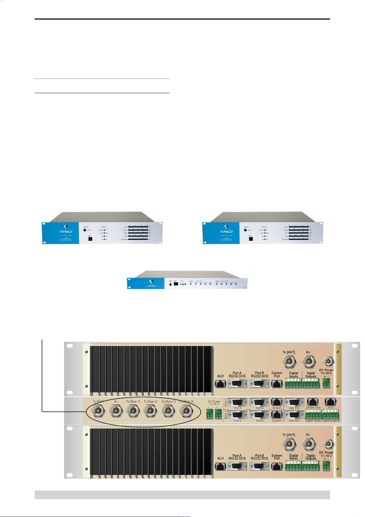
The EH450 is a fully redundant, hot standby digital data radio base /
repeater station providing automatic changeover facilities.
The EH450 is designed as a modular solution, comprising 2 identical
EB450 base station units (standard) linked to a central, fail-safe
monitoring and changeover controller (Hot Standby Controller). Either
base station may be taken out for maintenance without the need for
any system down time. The automatic changeover is triggered by out
of tolerance (alarm) conditions based on either RF and/or user data
throughput parameters.
Features and Benefits
Individual and identical base stations with separate control logic
changeover panel
Modules are hot swapable without user downtime
Flexible antenna options single, separate Tx & Rx, two Tx
and two Rx
Both on-line and off-line units monitored regardless of active
status
Also refer to the common Features and Benefits list of the E
Series Data Radio
Base / Repeater Unit
Note: RF connectors not used on ETSI version
Base / Repeater Unit
Hot Standby Controller Unit
Rear View
© Copyright 2004 Trio DataCom Pty. Ltd.
Page 33

E Series Data Radio User Manual
Part E Getting Started - EH450
Operational Description
The Hot Standby Controller (HSC) unit is a 1RU rack mounted
module that interfaces to two physically separate base stations (each
2RU rack mounted modules) via a number of RF and data cables.
Both base stations are operating simultaneously and both units are
constantly receiving signals, however only data from one base
station, the online base station is directed to the user equipment. The
online base station is the only base station transmitting at any time.
The Hot Standby Controller has the following functions:
Diplex the transmit and receive paths (Assuming internal
duplexer fitted), TX Only.
Amplify and split the incoming signal two ways so both base
stations receive at once.
Monitor status reports from both base stations to identify faults
and swap over the online base station if required.
Switch the antenna via internal coaxial relay duplexer to the
online base station transmitter and inhibit the offline base station
from transmitting.
Switch the User A and B data ports through to the online base
station.
An optocoupler based switch in the base station controller directs data
to and from ports A and B on the rear panel directly to ports A and B
on the on-line base station without any involvement from the Hot
Standby controller microcontrollers (apart from selecting the on-line
base). This provides protection of the system from failure of the
microcontroller.
Mounting and Environmental
Considerations
The EH450 Hot Standby Base Station is housed as a 5RU 19 rack
mounted set, encompassing 2 x 2RU Base Station units and 1 x 1RU
Hot Standby Controller unit. The mounting holes on the front panels
should be used to secure the units to the rack.
The unit should be mounted in a clean and dry location, protected from
water, excessive dust, corrosive fumes, extremes of temperature and
direct sunlight. Please allow sufficient passive or active ventilation to
allow the radio modems heatsink to operate efficiently.
All permanent connections are made at the rear of the unit. This
includes: Power, Antenna, Communications Ports, Digital I/O and
System Port. The front panel has an additional System Port
connection point for easy access.
The Base Station front panel system ports must not be used while in
this configuration.
As well as ports A and B, each base has a system port. The system
port of each base station is interfaced to the microcontroller on the Hot
Standby controller. This allows the microcontroller in charge of
selecting the base station to receive diagnostic messages from each
base station to decide their health.
The base station has its own system port on the rear panel and this is
interfaced to the Hot Standby Controller Module. The HSC will route
diagnostics at the rear panel system port to and from the system ports
of the base stations.
Warning
The base station front panel system port has priority over the rear
panel port, which is used for communication between the base station
and the Hot Standby Controller. This is to permit service personnel to
reconfigure the base station module without disconnection from the Hot
Standby Controller. It should be noted however, that when the front
panel port is accessed, a changeover event will occur due to lost
communications with the Hot Standby Controller.
Page 34
© Copyright 2004 Trio DataCom Pty. Ltd.
E Series Data Radio User Manual
Part E Getting Started - EH450
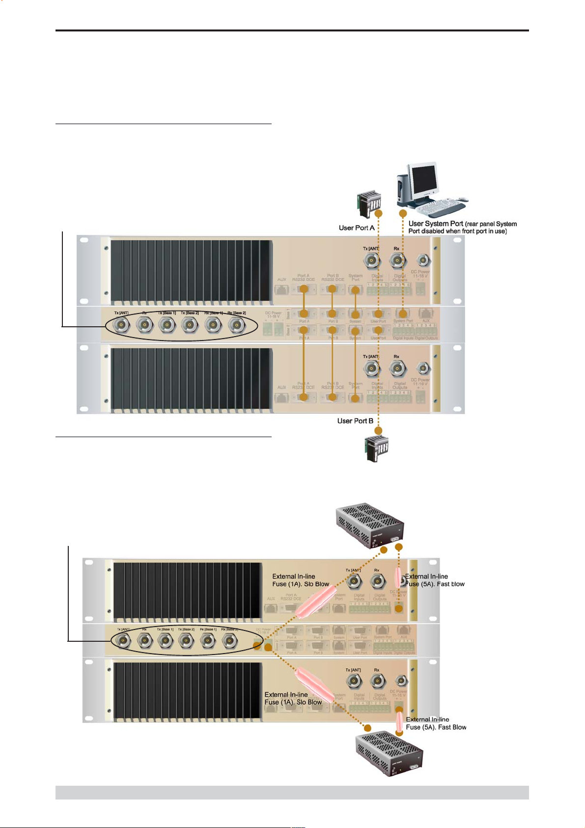
Communications Ports
The A & B Data Ports and System Ports of each Base Station
connect directly to the Hot Standby Controller units corresponding
ports with the cables provided. Ensure all clamping screws on the
Data Port cables are firmly secured and the System Port cables are
clipped in correctly. See figure below for further details.
Note: Only the front or rear User System Port can be used at any
one time on the Hot Standby Controller.
Note: RF Connectors not used on ETSI version
The Hot Standby Controller units A & B Data Ports connect directly to
you application device and the System Port connects directly to your
local PC. See ER450 Quick Start Guide Section for further details.
Power Supply and Protection
The EH450 has facilities for dual power supplies to provide for a
redundant system. A separate power supply should be used for each
of the Base Station units. The Hot Standby Controller unit has
connections for dual power supplies and it is recommended that the
power supplies from each of the Base Stations also be used to power
the Hot Standby Controller unit. See Figure below for further details.
See ER450 Quick Start Guide Section for detailed wiring information.
Note: RF Connectors not used on ETSI version
© Copyright 2004 Trio DataCom Pty. Ltd.
Page 35
E Series Data Radio User Manual
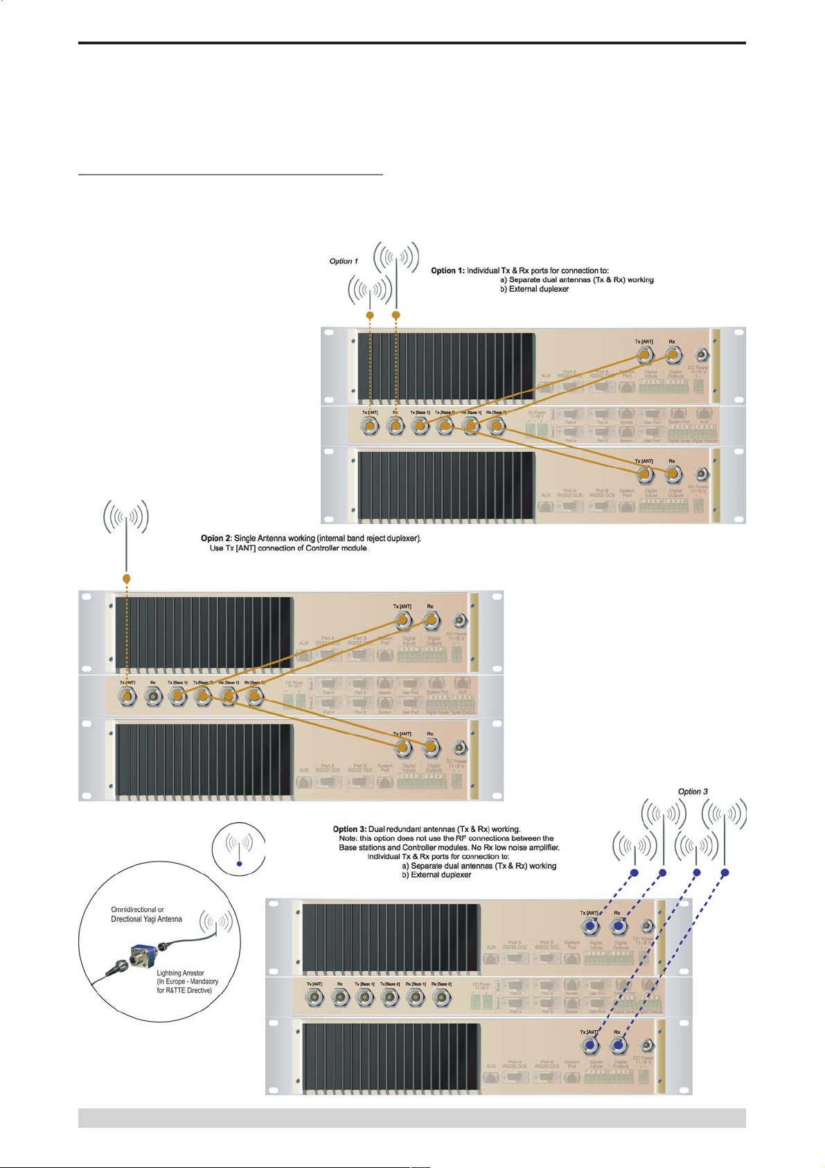
Connecting Antennas and RF Feeders
There are 3 primary antenna connection options. All connectors used
are standard N Type sockets. See figures below for further details.
See ER450 Quick Start Guide for detailed wiring information.
Part E Getting Started - EH450
Page 36
© Copyright 2004 Trio DataCom Pty. Ltd.
E Series Data Radio User Manual
Front Panel Operation
Part E Getting Started - EH450
Switches
Select Switch
The 3 position switch (1 / Auto / 2) on the front panel provides the
following functionality:
Position 1: base station 1 is forced into operation
Position Auto: changeover hardware will select the online base
station
Position 2: base station 2 is forced into operation
The select switch is also used to identify the target base station for
configuration programming.
Adjacent to the select switch are two LEDs: These LEDs indicate the
current active base station.
Select LEDs
Green - Auto Mode
Red - Remote Force
Amber - Local Force
2 Green Firmware Download
2 Amber Test Mode
2 Red Fatal Error - refer User Manual
Reset Switch
This is a momentary close switch which when depressed will reset all
LED alarm indications.
System Port
There are two system port connection points, one on the rear panel
and one on the front panel. Both have the same functionality and can
be used for local diagnostics, firmware front panel downloads and hot
standby controller testing. To access the system port use the
diagnostic/programming cable supplied.
Note: When connection is made to front panel system rear system
port is disabled.
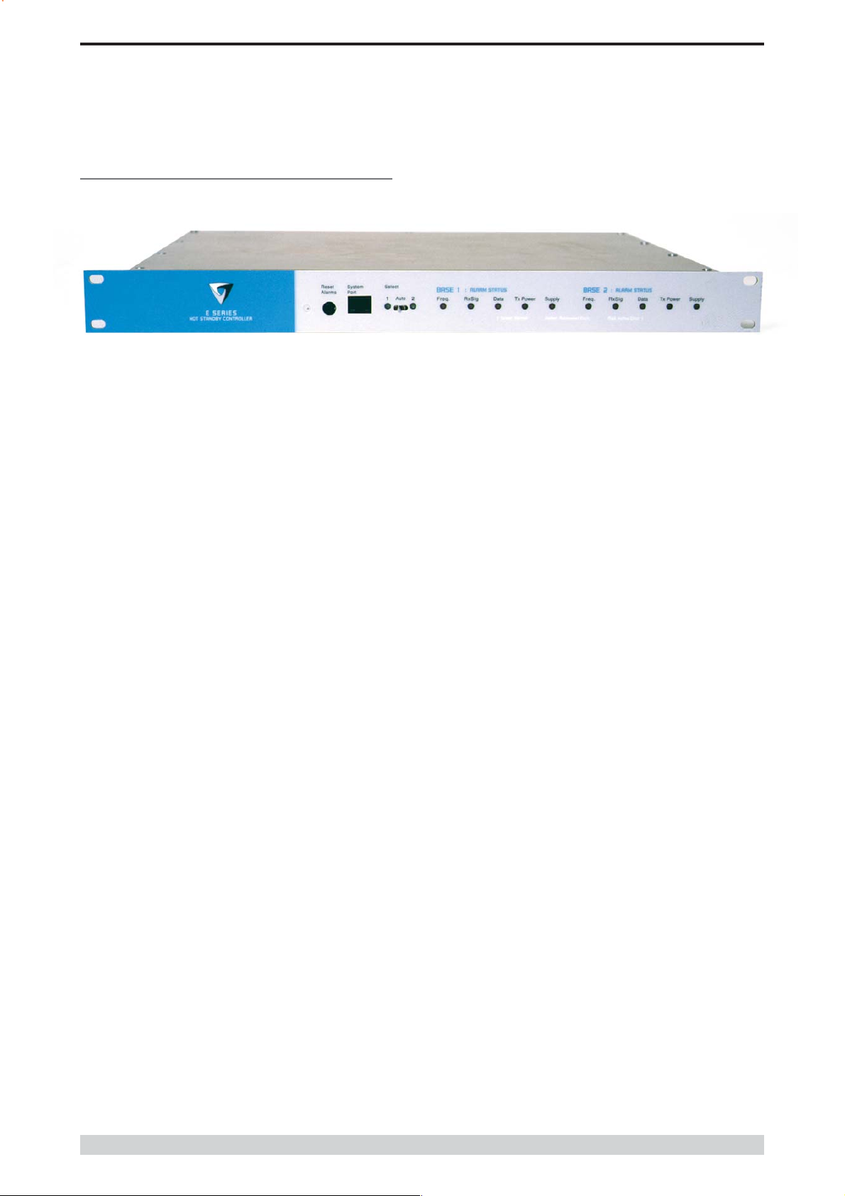
Alarm Status LEDs
There are 10 alarm LEDs on the front panel, five for base 1 and five for
base 2. These LEDs provide a general indication of base station
status. More detailed base station status information is available by
using the diagnostic utility software.
The indicated alarms for each base station are:
Freq. => Frequency Error
RxSig => Receive Signal (RF) Error
Data => Receive Data Error
TxPower => Transmit Power (RF) Error
Supply => DC Voltage Error
The status of each alarm is represented as follows:
OFF => Unknown
Green => No Error
Red => Current (active) Error condition
Amber => Recovered Error condition
© Copyright 2004 Trio DataCom Pty. Ltd.
Any active or recovered error LEDs will turn to green after the reset
alarms switch has been pushed or remotely reset.
Page 37

E Series Data Radio User Manual
Part F - Operational Features
Part F Operational Features
Multistream functionality (SID
codes)
The E Series sends data messages in packets. A feature of the E
Series is that an address can be embedded in each packet. This
address is called the stream identifier code (SID).
By configuring a user serial port for a specific SID code, it is
possible to steer messages to similarly configured ports between
radio modems. In effect, it is possible to use the multiple serial
ports available on the E Series, to enable multiple protocols to
share the same RF channel. The SID codes also facilitate the use
of other features such as TView diagnostics. Unique selective
routing, repeating, and data splitting functions available in the radio
modems configuration allow data steering and bandwidth
management in complex systems.
See Part I - TView+ Management Suite - Programmer and Part J TView Remote Diagnostics and Network Controller for details.
Collision Avoidance (digital and
RFCD based)
Where multiple unsynchronised protocols coexist on a common
multiple access radio channel, there is always a possibility that
both hosts may poll different remote devices at the same time. If
both devices attempt to answer back to the single master radio at
the same time, it follows that a collision could occur on the radio
channel.
RF Carrier Detect RSSI based Collision
Avoidance
In half duplex systems, the receivers RF carrier detect is used to
inhibit the transmitter whilst a signal is being received.
Digipeater Operation
A feature of the E Series radio modems is the ability to internally
repeat data packets to provide stand alone repeater facilities
without the need for external intelligence.
This is done by programming SID Codes to Repeat a stream or
range of streams. Wizard templates can be used to simplify setup
of this and other features.
See Part I - TVIEW+ Management Suite for details.
TVIEW+ Diagnostics
The E Series has an inbuilt remote configuration and diagnostics
utility.
This facility allows transparent remote access to the key
configuration and operating parameters of the radio.
See Part J - TView Remote Diagnostics and Network Controller for
details.
Poor VSWR Sensing
To facilitate the operation of multiple protocol operation on the
radio channel, a transparent collision management system has been
implemented : See Part I - TView+ Management Suite - Programmer
for details.
Digital Collision Avoidance System
If the multiple access master has been configured for full duplex
operation, it is possible to use the inbuilt collision avoidance signalling
system.
Once the master radio receives a valid incoming data stream from a
remote, a flag within the outbound data stream is used to alert all
other remote devices that the channel has become busy. Remote
devices wishing to send data will buffer the message until the channel
status flag indicates that the channel is clear. A pseudo-random timing
value is added to the retry facility to ensure that waiting remotes do not
retry at the same time.
To protect the transmitter, forward and reverse power are measured on
each transmission.
If a VSWR of 3:1 or greater is measured, transmitter output power is
reduced to +31 dBm.
Page 38
© Copyright 2004 Trio DataCom Pty. Ltd.
E Series Data Radio User Manual
Part G Commissioning
Part G Commissioning
Check DC power connector for correct voltage (10-16VDC) and
polarity, BEFORE plugging in the power connector.
Power-up
Upon power up, the radio will self test and shortly after the green
power LED will be displayed.
Failure of the power LED to light indicates no power, or failure of the
fuse due to incorrect polarity or over-voltage.
Other failure such as fatal internal errors will initiate error modes as
detailed in Part E - Getting Started: LED Indicators and Test Outputs.
LED Indicators
Will depend on the system architecture. If the device is a remote site
receiving a base station with a constant carrier, then the RXSIG/
SYNC LED should be green to indicate healthy reception of the
wanted signal.
If the site has been configured as a constantly transmitting base station,
then the PWR/TX LED should show red.
In other types of systems, TX and RX bursts would be indicated by
the RX or TX LEDs as above.
Data flow to and from the user ports is indicated by the TXD/RXD
LEDs for each port.
(See Part E Getting Started: LED Indicators and Test Outputs.)
Data Transfer Indications
Bi-colour LEDs are provided to indicate RS232 data being transmitted
and received on each data port. A RED flash indicates a byte (or
bytes) of incoming data from the serial line which will be transmitted to
air, and a green flash indicates a byte of data received off air being
released onto the serial line.
If data is being sent to the radio modem and the Data LED does not
flash RED, this may indicate a wiring or configuration problem. Check
that the TX and RX data lines are correctly wired (see Part E Getting
Started: LED Indicators and Test Outputs).
Also check that character set and parity settings (i.e. N,8,1 etc) are set
identically at the terminal and the radio modem. Note that some
incorrect settings of the character set parameter can still produce
transmittable data, even though the data will not be understood by the
application.
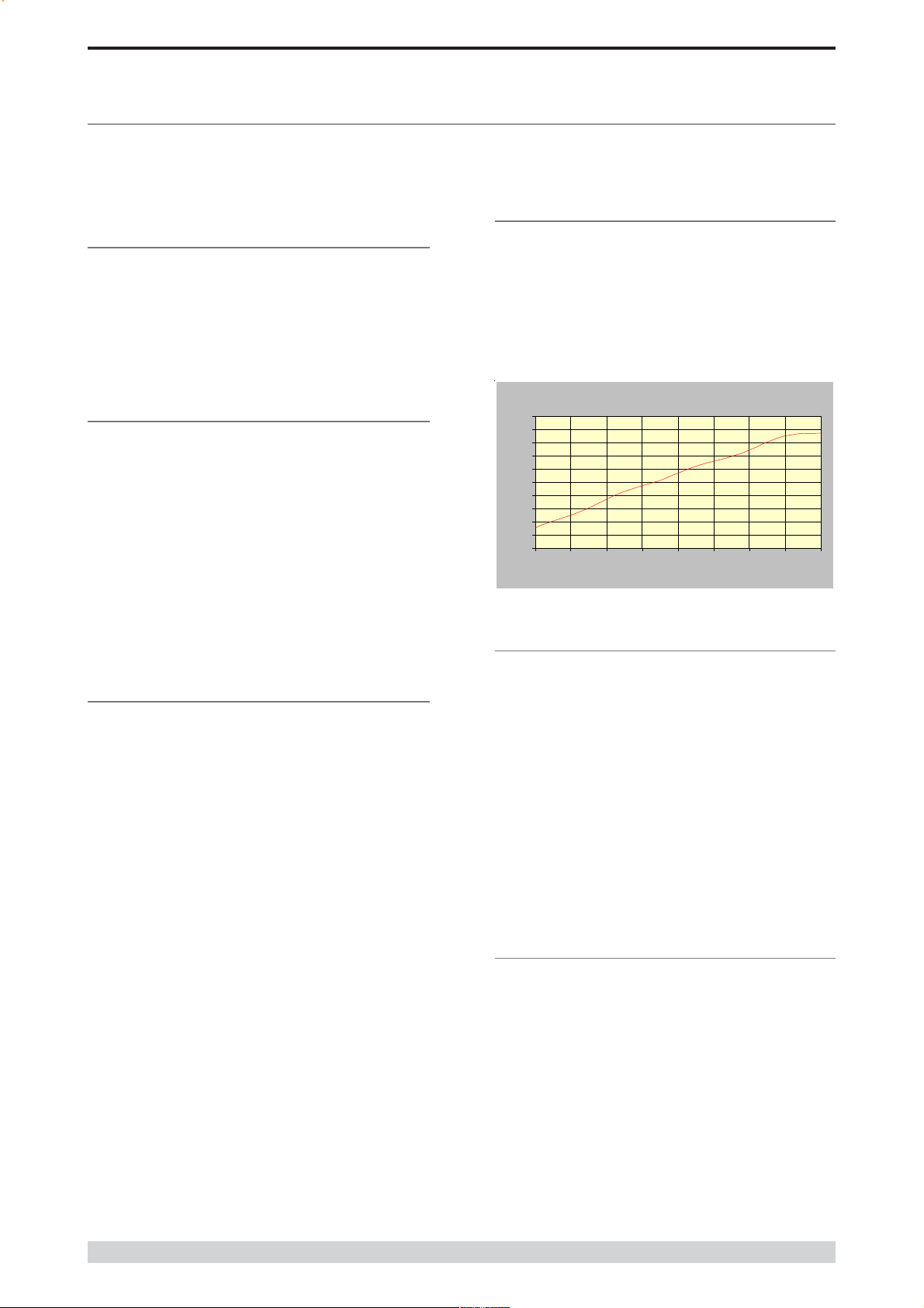
Antenna Alignment and RSSI
Testing
Once the RXSIG LED is lit, it is possible to confirm RX signal strength
and align a directional antenna by monitoring the RSSI output.
This DC voltage appears at Pin 9 of Port B.
A ground reference can be obtained from chassis ground or Pin 5 of
Port A or B.
The chart below shows Pin 9 voltage as it relates to signal strength.
Analog RSSI Output Char acteristi cs - E Series Da t a R adio
5
4.5
4
3.5
3
2.5
2
1.5
RSSI (DC Volts)
1
0.5
0
-120 -110 -100 -90 -80 -70 -60 -50 -40
RF Level (dBm)
Link Establishment and BER
Testing
Once communications has been established, it is possible to confirm
the packet error rate performance of the radio path, and thus estimate
the BER figure.
There are a number of tools provided to do this. The easiest is to use
the indicative packet error test provided within the TVIEW+
Diagnostics under statistical performance tools. Alternatively, it is
possible to use hyper terminal, or other packet test instruments or PC
programs to run end to end or perform loopback testing.
Please note that when using a loopback plug some understanding of
the packetising process is necessary, since each test message must
be carried in a single packet for meaningful results to be obtained.
Note also that in PTMP systems, allowance must be made for
collision potential if other data is being exchanged on the system.
VSWR Testing
VSWR testing is achieved using specialized VSWR testing
equipment, or a Thruline power meter that measures forward and
reverse power.
© Copyright 2004 Trio DataCom Pty. Ltd.
VSWR is the ratio between forward and reflected transmitter power,
and indicates the health and tuning of the antenna and feeder system.
VSWR should be better than 3 to 1, or expressed as a power ratio,
<6dB or no more than 25%. To activate the radios transmitter for
VSWR testing, use:
a) An RTS loop
b) A system port PTT plug
Page 39
 Loading...