

Schneider Electric Systems Canada EB450-XXF01 Users Manual

E Series Data Radio – User Manual
Front Panel Operation
Part E Getting Started - EH450
Switches
Select Switch
The 3 position switch (1 / Auto / 2) on the front panel provides the
following functionality:
• Position 1: base station 1 is forced into operation
• Position Auto: changeover hardware will select the online base
station
• Position 2: base station 2 is forced into operation
The select switch is also used to identify the target base station for
configuration programming.
Adjacent to the select switch are two LEDs: These LEDs indicate the
current active base station.
Select LED’s
• Green - Auto Mode
• Red - Remote Force
• Amber - Local Force
2 Green Firmware Download
2 Amber Test Mode
2 Red Fatal Error - refer user manual
Reset Switch
This is a momentary close switch which when depressed will reset all
LED alarm indications.
System Port
There are two system port connection points, one on the rear panel
and one on the front panel. Both have the same functionality and can
be used for local diagnostics, firmware front panel downloads and hot
standby controller testing. T o access the system port use the
diagnostic/programming cable supplied.
Note: Wnen connection is made to front panel system rear system
port is disabled.
Alarm Status LEDs
There are 10 alarm LEDs on the fron panel, five for base 1 and five for
base 2. These LEDs provide a general indication of base station
status. More detailed base station status information is available by
using the diagnostic utility software.
The indicated alarms for each base station are:
Freq. => Frequency Error
RxSig => Receive Signal (RF) Error
Data => Receive Data Error
TxPower => Transm it Power (RF) Er ror
Supply => DC Voltage Error
The status of each alarm is represented as follows:
Green => No Error
Red => Current (active) Error condition
Amber => Recovered Error condition
Any active or recovered error LEDs will turn to green after the reset
alarms switch has been pushed or remotely reset.
© Copyright 2002 Trio DataCom Pty. Ltd.
Page 35

E Series Data Radio – User Manual
Part F - Operational Features
Part F Operational Features
Multistream functionality (SID
codes)
The E Series sends data messages in packets. A feature of the E
Series is that an address can be embedded in each packet. This
address is called the stream identifier code (SID).
By configuring a user serial port for a specific SID code, it is
possible to steer messages to similarly configured ports between
radio modems. In effect, it is possible to use the multiple serial
ports available on the E Series, to enable multiple protocols to
share the same RF channel. The SID codes also facilitate the use
of other features such as TView diagnostics. Unique selective
routing, repeating, and data splitting functions available in the radio
modems configuration allow data steering and bandwidth
management in complex systems.
See Part I - TView+ Management Suite - Programmer and Part J TView Remote Diagnostics and Network Controller for details.
Collision Avoidance (digital and
RFCD based)
Where multiple “un synchronised” protocols co-exist on a common
“multiple access” radio channel, there is always a possibility that
both “hosts” may poll different “remote” devices at the same time. If
both devices attempt to answer back to the single master radio at
the same time, it follows that a collision could occur on the radio
channel.
RF Carrier Detect RSSI based Collision
Avoidance
In half duplex systems, the receiver’s RF carrier detect is used to
inhibit the transmitter whilst a signal is being received.
Digipeater Operation
A feature of the E Series radio modems is the ability to internally
repeat data packets to provide stand alone repeater facilities
without the need for external intelligence.
This is done by programming “SID Codes” to “Repeat” a stream or
range of streams. Wizard templates can be used to simplify setup
of this and other features.
See Part I - TVIEW+ Management Suite for details.
TVIEW+ Diagnostics
The E Series has an inbuilt remote configuration and diagnostics
utility.
This facility allows transparent remote access to the key
configuration and operating parameters of the radio.
See Part J - TView Remote Diagnostics and Network Controller for
details.
To facilitate the operation of multiple protocol operation on the
radio channel, a transparent collision management system has been
implemented : See Part I - TView+ Management Suite - Programmer
for details.
Digital Collision Avoidance System
If the “multiple access master” has been configured for full duplex
operation, it is possible to use the inbuilt collision avoidance signaling
system.
Once the master radio receives a valid incoming data stream from a
remote, a flag within the “outbound” data stream is used to alert all
other remote devices that the channel has become busy. Remote
devices wishing to send data will buffer the message until the channel
status flag indicates that the channel is clear. A pseudo-random timing
value is added to the retry facility to ensure that waiting remotes do not
retry at the same time.
Page 36
© Copyright 2002 Trio DataCom Pty . Ltd.
E Series Data Radio – User Manual
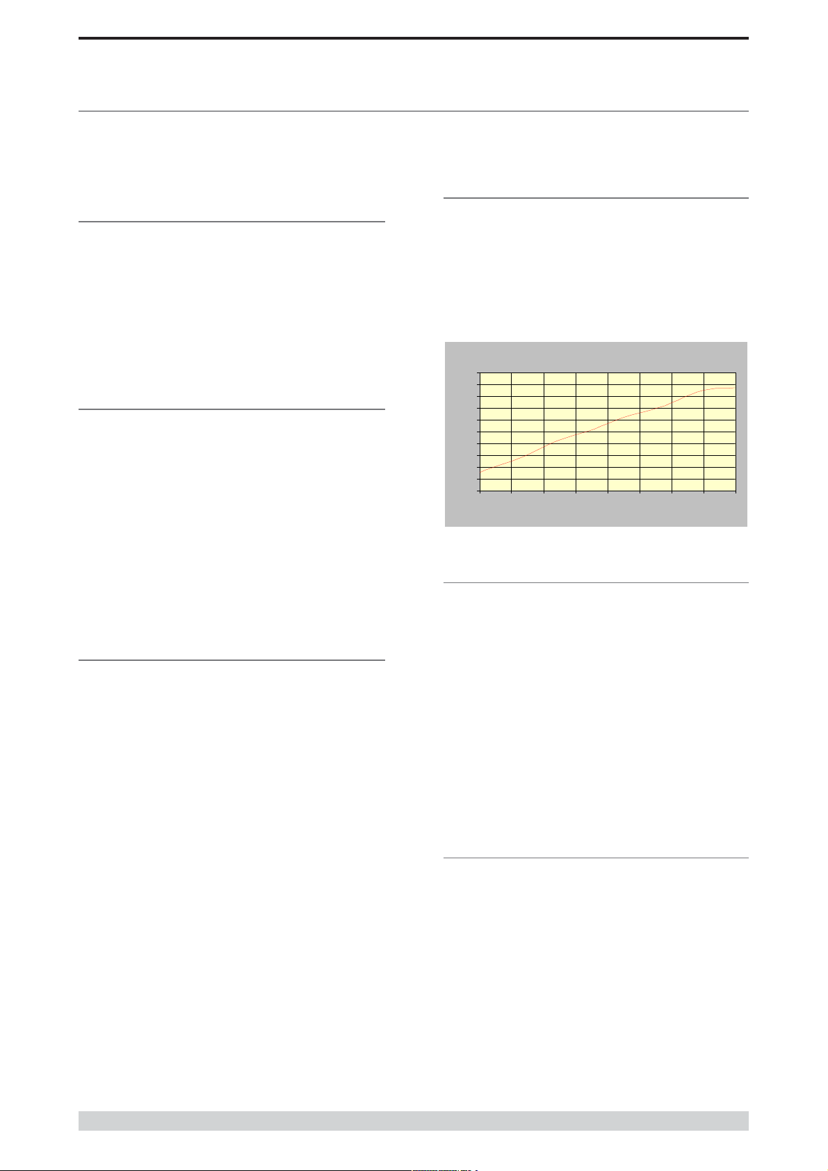
Analog RSSI Output Ch aracteristics - E Seri es Data Radi o
0
0.511.522.533.544.55-120
-110
-100
-90
-80
-70
-60
-50
-40
RF Level (dBm)
)
Part G Commissioning
Part G Commissioning
Check DC power connector for correct voltage (10-16VDC) and
polarity, BEFORE plugging in the power connector.
Power-up
Upon power up, the radio will self test and shortly after the green
power LED will be displayed.
Failure of the power LED to light indicates no power, or failure of
the fuse due to incorrect polarity or over-voltage.
Other failure such as fatal internal errors will initiate error modes
indicated by a flashing sequence of all LEDS red, followed by one
or more green LED’s to indicate the nature of the failure (see Part E
– Getting Started: LED Indicators and Test Outputs).
LED Indicators
Will depend on the system architecture. If the device is a remote site
receiving a base station with a constant carrier, then the RXSIG/
SYNC LED should be green to indicate healthy reception of the
wanted signal.
If the site has been configured as a constantly transmitting base station,
then the PWR/TX LED should show red.
In other types of systems, TX and RX bursts would be indicated by
the RX or TX LED’s as above.
Data flow to and from the user ports is indicated by the TXD/RXD
LEDs for each port.
(See Part E – Getting Started: LED Indicators and Test Outputs.)
Data Transfer Indications
Bi-colour LEDs are provided to indicate RS232 data being
transmitted and received on each data port. A RED flash indicates
a byte (or bytes) of incoming data from the serial line which will be
transmitted to air, and a green flash indicates a byte of data
received “off air” being released onto the serial line.
If data is being sent to the radio modem and the Data LED does
not flash RED, this may indicate a wiring or configuration problem.
Check that the TX and RX data lines are correctly wired (see Part E
– Getting Started: LED Indicators and Test Outputs).
Also check that character set and parity settings (i.e. N,8,1 etc) are
set identically at the terminal and the radio modem. Note that some
incorrect settings of the character set parameter can still produce
transmittable data, even though the data will not be understood by
the application.
Antenna Alignment and RSSI
Testing
Once the RXSIG LED is lit, it is possible to confirm RX signal strength
and align a directional antenna by monitoring the RSSI output.
This DC voltage appears at Pin 9 of Port B.
A ground reference can be obtained from chassis ground or Pin 5 of
Port A or B.
The chart below shows Pin 9 voltage as it relates to signal strength.
RSSI (DC Volts
Link Establishment and BER
Testing
Once communications has been established, it is possible to confirm
the packet error rate performance of the radio path, and thus estimate
the BER figure.
There are a number of tools provided to do this. The easiest is to use
the “indicative packet error test” provided within the TVIEW+
Diagnostics under “statistical performance tools”. Alternatively, it is
possible to use hyper terminal, or other packet test instruments or
PC programs to run end to end or perform “loopback” testing.
Please note that when using a “loopback plug” some understanding of
the packetising process is necessary, since each “test message’ must
be carried in a single packet for meaningful results to be obtained.
Note also that in PTMP systems, allowance must be made for
collision potential if other data is being exchanged on the system.
VSWR Testing
VSWR testing is achieved using specialized VSWR testing
equipment, or a “Thruline” power meter that measures forward and
reverse power.
© Copyright 2002 Trio DataCom Pty. Ltd.
VSWR is the ratio between forward and reflected transmitter
power, and indicates the health and tuning of the antenna and
feeder system.
VSWR should be better than 3 to 1, or expressed as a power ratio,
<6dB or no more than 25%. To activate the radios transmiter for
VSWR testing, use:
a) An RTS loop
b) A system port PTT plug
Page 37

E Series Data Radio – User Manual
Part H Maintenance
Routine Maintenance
Considerations
The E Series hardware itself does not require routine maintenance.
However all radio products contain crystal frequency references,
and the stability of these crystals changes with time. The effect of
this is that the product will slowly drift off frequency, and eventually
it will require re-calibration. E Series radios are designed with high
quality, low drift specification references, to ensure a long
maintenance free lifespan. The length of this lifespan will depend
on the severity of temperature extremes in the operating
environment, but is normally 3–5 years. Extended frequency drift
can be detected using TVIEW+ Diagnostics “Freq error” parameter.
Generally, recalibration is achieved by replacing the radio in the
field with a spare, and returning the radio to a service centre for recalibration and specification testing at moderate cost.
Part H Maintenance
Routine maintenance should be performed on external equipment
subject to greater environmental stresses including antennas, RF
feeder cables, backup batteries and cooling fans (if required). This
maintenance should include testing of site commissioning figures
such as received signal strength, VSWR, P/S voltage etc.
Page 38
© Copyright 2002 Trio DataCom Pty . Ltd.

E Series Data Radio – User Manual
SECTION 2 TVIEW+ Management Suite
SECTION 2
Part I TVIEW+ Management Suite Programmer
Part J TVIEW Remote Diagnostics and
Network Controller
Part K Appendices
Part L - Support Options
© Copyright 2002 Trio DataCom Pty. Ltd.
Page 39

E Series Data Radio – User Manual
Part I TVIEW+ Management Suite - Programmer
Part I TVIEW+ Management Suite Programmer
Introduction
This manual covers the installation and operation of the E Series
TVIEW+ Management Suite which incorporates 3 utilities:
• Programmer for configuration of the radio RF parameters,
system parameters and data ports
• Diagnostics* for real-time monitoring and logging of radio
performance parameters
• Firmware Update for loading new firmware releases into the
radio data modem
All utilities can be run on any IBM compatible computer running
Windows 95® and above. This section describes use of the
programmer and firmware Update utilities in detail. Users should refer
to the separate Diagnostics section for information about this utility.
The programmer is used to set configuration parameters within the
ER450 data radio modem and EB450 base station. The utility permits
configuration of modems connected directly to the PC as well as over
the air to a remote unit. Configuration parameters can be saved to a
disk file for later retrieval, or used for clone programming of other
modems.
All configuration parameters are held in non-volatile memory
(NVRAM) on the Data Radio Modem. Configuration is fully
programmable via the Systems Port using the programming adaptor
and cable supplied. Disassembly of the unit is not required for any
reason other than for servicing.
The diagnostics utility permits monitoring and logging of radio
performance parameters for both E Series* as well as D Series* data
radio modems and base stations. It supports homogeneous systems
of radios as well as mixed systems of both E and D series radios.
The firmware update utility permits field upgrade of the firmware in an
ER450 data radio modem, EB450 base station and EH450 hot
standby unit connected directly to the PC. A special serial adaptor
cable is required to be connected to Port B to load firmware into the
unit.
Installation
Unit Connection
Programmer and Diagnostics Utilities
The unit is connected to the PC using the supplied DB9-RJ45 adaptor
cable (part no. TVIEW+ Cable) for local configuration changes or
diagnostic monitoring. The cable should be connected to the RJ45
System Port of the unit and a valid PC serial port (eg; COM 1) DB9
connector.
(See Part E - Getting Started: Communications Ports)
Firmware Update Utility
The unit to be updated with firmware connects to the PC using the
DB9-DB9 adaptor (part no. DRPROG). The cable should be
connected to the DB9 Port B connector on the unit and a valid PC
serial port (See Appendix C for details) DB9 connector.
Software
Please take a moment to read this important information before you
install the software.
The installation of this Software Suite is a 2 step process.
Step 1 completes the typical installation of the TVIEW+ Management
Suite and will install the Programming Software together with the E
Series Documentation.
Step 2 installs the Diagnostic Software and is optional. This step is
only required if your radios have Remote Diagnostics enabled.
STEP 1: Installation - TVIEW+ Management
Suite
Note: If a previous version of the TVIEW+ Management Suite has
been installed on your PC, you must uninstall it via Control Panel
“Add/Remove Programs”.
• Close down all other programs currently running.
* Requires the optional DIAGS Network Management and Remote
Diagnostic Facility to be installed - per radio.
Page 40
• Place the CD-ROM in the drive on the PC.
• Using Windows Explorer locate the files on the CD-ROM.
• In Windows Explorer double click on the file called
TVIEW+_(Version#)_install.exe
• After the installer starts follow directions.
© Copyright 2002 Trio DataCom Pty . Ltd.
E Series Data Radio – User Manual
Part I TVIEW+ Management Suite - Programmer
STEP 2: Installation - TView Diagnostic
Software (Optional)
Note: If a previous version of the “TView WinDiags” software has
been installed on your PC, you must uninstall it via Control Panel
“Add/Remove Programs”.
• Close down all other programs currently running.
• Place the CD-ROM in the drive on the PC.
• Using Windows Explorer open the “Diagnostics” directory on
the CR-ROM.
• Double click on the file called setup.exe
• After the installer starts follow directions.
Other:
The current E Series Manuals are supplied and installed as part of the
TVIEW+ Management Suite installation in Adobe Acrobat format.
Adobe Acrobat Reader is provided on the CD-ROM for installation if
required.
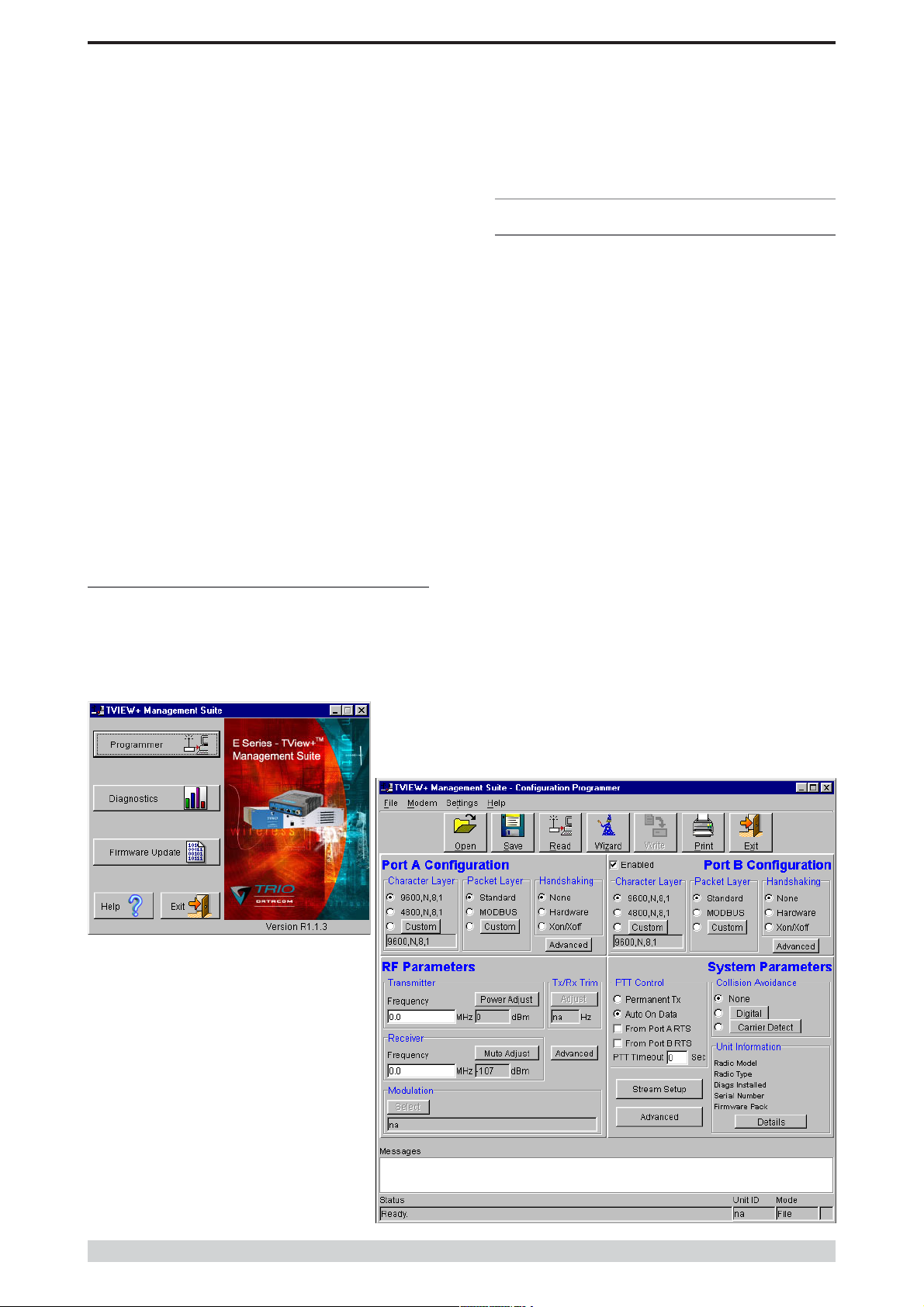
TVIEW+ Front Panel
When started the TVIEW+ front panel appears. The larger buttons
permit each of the three utilities to be started. The diagnostics button
may be greyed out if this utility has not been installed or found in the
correct file directory. Access to local help and an exit facility are
provided by the remaining 2 buttons.
Programmer
Main Window
When first started the programmer is in file mode as indicated by the
mode field at the bottom right of the panel shown below. In this mode it
is possible to open a previously saved configuration file, or configure
various programming options and save the configuration to a file.
Note: Modulation type is not available in this mode.
T o commence programming a unit (radio remote or base station) a
session must first be established by using the “READ” function. This
function reads the current configuration from the unit and displays it in
the main window. The “mode” displays changes to local or remote
depending on the type of session selected at the read function. Several
options in the main window may be blanked out until a session has
been established with a unit.
Note: Changing any item on the menu will in general not take effect
until data is written back to the unit using the “WRITE” function.
The procedure to follow for normal programming of unit is:
• Read unit
• Configure parameters (or Open a previously saved
configuration file)
• Write unit
Several modems of the same radio type can be programmed with the
same configuration using the clone facility described in Clone Mode. It
is important to note that when using this facility the cloned radio should
be of the same type to ensure it does not operate outside its capability.
© Copyright 2002 Trio DataCom Pty. Ltd.
Page 41
E Series Data Radio – User Manual
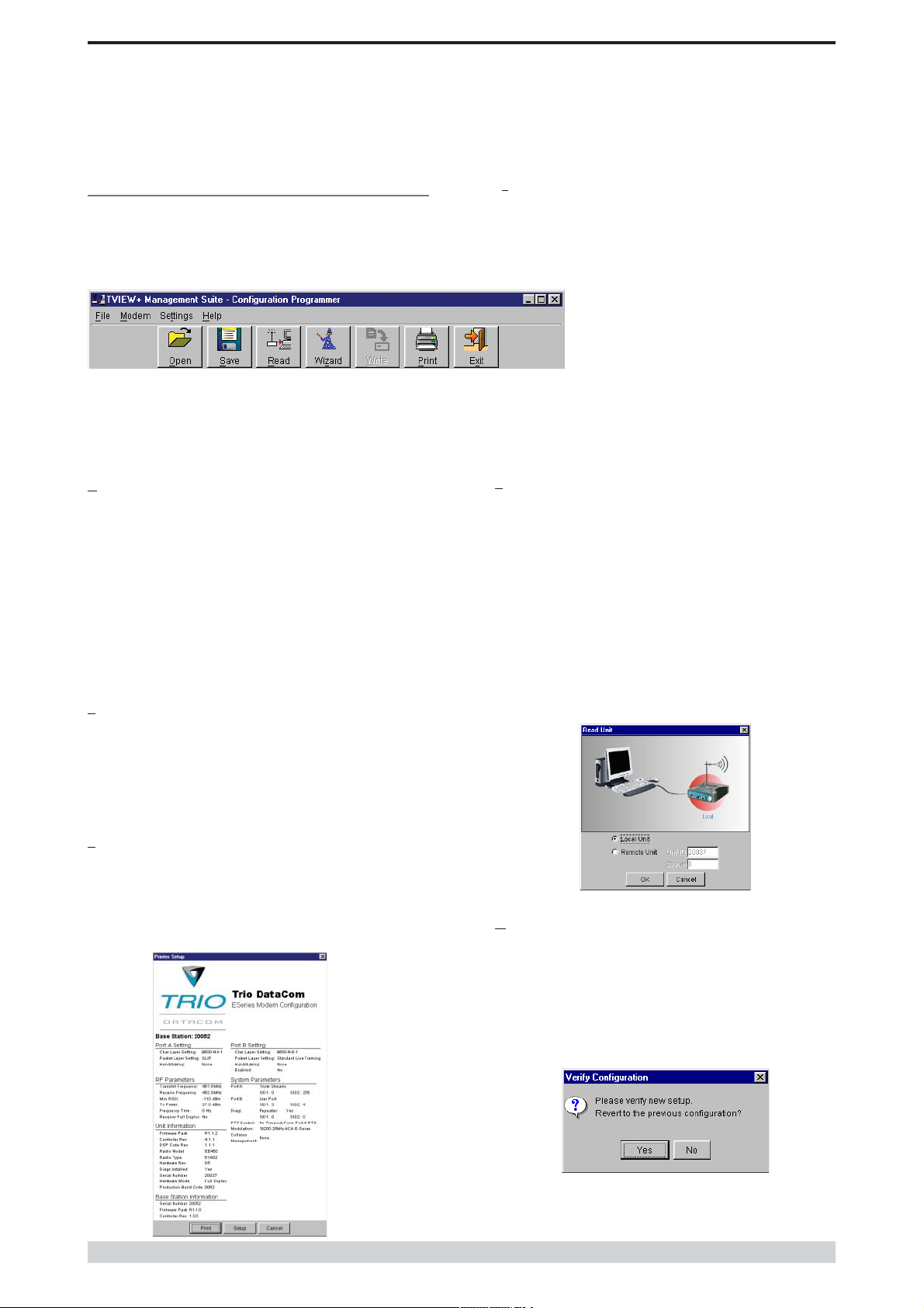
Pull Down Menus and Toolbar Buttons
The items on the pull-down menus can be selected either directly with
a mouse or using the ALT key in combination with a HOT KEY (eg
ALT-F to select the file menu). Several of the functions within each
menu are also available on the toolbar (click once to select).
File Menu
The file menu allows the user to load (open) or save configuration data
as well as to quit the program. The files are saved with an “.cfg” file
extension
Open (also available on the toolbar)
This function is used to load an existing configuration file that can be
used to directly program the radio or to use as a starting point to edit
configuration parameters. Note that a session must be established
with the unit by initially reading the configuration parameters from the
unit prior to being written to a unit.
If in file mode the modulation type will not be displayed. If in local/
remote mode and a file that was saved from local/remote mode is
opened, then modulation type will be imported and used, but only if it
is valid for the connected hardware. If not then the units read
modulation type will be used.
Save (also available on the toolbar)
Part I TVIEW+ Management Suite - Programmer
xit (also available on the toolbar)
E
This function terminates the program. The user is requested to confirm
this selection before exiting the application.
Modem Menu
This radio menu allows configuration data to be read
from and written to the unit (remote radio or base
station) using the selected PC serial port connection
(see Settings menu). The action of reading the
configuration establishes a session with the unit.
Communications is maintained with the unit to ensure
that the session remains open. If the session has been lost due to data
transmission errors or disconnection of the programming cable it will
need to be re-established to ensure any updated configuration is written
successfully to the unit.
Read (also available on the toolbar)
This function establishes a session with the unit, reads configuration
data from the unit and displays it in the programmer main window.
When selected a dialogue window appears prompting the user to
choose whether the unit to read is local (connected directly to the serial
port or remote (connected over the air to the unit connected to serial
port). Unit no. (serial no.) musty be entered and the stream SID code
is “on” (default =0)). After configuration data is read from the unit it is
available for editing and writing back to the unit or saving to a file. The
progress of data transfer to or from the unit is indicated by a message
window as well as a rotating indicator in the bottom right hand corner
of the main window.
This function is used to save the current configuration parameters to a
file for future recall.
If in “file mode” only basic RF , Port and System parameters are
saved and re called. If in local/remote mode then modulation type is
saved and re called.
Print (also available on the toolbar)
This function prints out the configuration data to the default printer in a
standard format. There are no options for this item.
This should be used if a complete record is required for site/unit
configuration. Firmware/Modulation/Diags/Hardware type are all
printed.
Write (also available on the toolbar)
This function writes configuration data displayed in the main window to
the unit and reboots the unit. When selected a dialogue window
appears prompting the user to confirm whether to proceed. A progress
indicator in the bottom right hand corner of the main window is
displayed while data is being read. This selection is only available if a
session has been previously established and maintained with the unit.
Page 42
© Copyright 2002 Trio DataCom Pty . Ltd.
E Series Data Radio – User Manual
Part I TVIEW+ Management Suite - Programmer
This dialog provides a facility for reversing any remote configuration
changes and reverting to the previous configuration.
Select “No” to send a command to the unit to accept the new
configuration changes and to close the session. Select “Yes” to send a
command to the unit to cancel the new configuration changes and to
close the session.
The configuration settings will revert to their previous values if the data
communications circuit with the unit has been interrupted after the new
changes have been made, but before they have been verified, as just
described, then the unit will automatically discard the new changes. A
“Timeout Error” message will appearin the event of such an
interruption and the programmer will revert back to file mode.
After configuration data has been written the session with the unit is
closed and the programmer goes back to file mode
NOTE: In general any change made on the programmer screen must
be written to the unit using this function before it becomes permanently
stored. Changes to Power Adjust, Mute Adjust and Tx/Rx Trim
however do take immediate effect to permit a tuning capability prior to
being permanent stored.
Cancel Session (also available on the toolbar)
This function closes the session with unit and puts the programmer
back into file mode. All configuration changes are discarded including
changes to Power Adjust, Mute Adjust and Tx/Rx Trim.
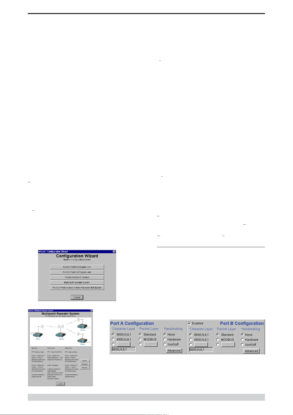
zard (also available on toolbar)
Wi
This function permits the user to select standard configurations after the
configuration from a unit has been read or a file opened. The user is
prompted via a series of dialogue windows to select the desired
configuration that can then be written to the unit (remote radio or base
station).
C
lone Mode
This function permits writing of the same configuration data to several
units. This feature is normally used for configuring data radio modems
connected locally. The procedure is:
• Read the configuration from the first unit
• Configure the parameters (or Open a previously saved
configuration file)
• Select Clone Mode (Modem menu)
• Write the configuration to the first unit
• The changes will take effect when repowered
• Connect the next unit
• Write the next unit which establishes a session and recognises
the unit serial number and type, and then configures the unit
• Repower the unit for changes to take effect
• Repeat the last 3 steps for the remaining units.
ttings
Se
This menu permits selection of the PC serial port (COM1 to COM4)
to be used for communications with the unit. COM1 is the default
selection and if a different port is to be used it must be set before
establishing a session by reading the configuration from a unit. Whilst
a session is established with a unit this menu can not be accessed.
Help
This menu permits selection of help information using the
key. W arnings regarding use of the programmer software using the
Warnings key and version detail using the About key .
Contents
Port A and Port B Configuration
Data from these two user ports is multiplexed for transmission over the
air. Each port can be configured separately for the Character layer
(Data speed, number of data bits, number of stop bits, parity), Packet
layer and Handshaking (flow control). Port B must be enabled if
required by setting the check box at the top of its configuration section.
if Port B is off, the 16K memory is split equally between Port A Rx/Tx
buffers (ie: 8K & 8 K). If Port B is on, then the 16K is split equally
across Port A & B Rx/Tx buffers (ie: 4K, 4K, 4K & 4K).
The following description is common to both ports.
© Copyright 2002 Trio DataCom Pty. Ltd.
Page 43
E Series Data Radio – User Manual
Part I TVIEW+ Management Suite - Programmer
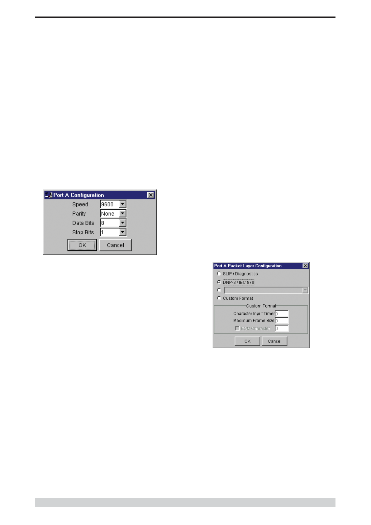
Character Layer
There are two standard formats and a custom format that can be
selected by checking the appropriate control button to the left of the
description. The standard formats are:
• 9600,N,8,1 (data speed = 9600 bps, no parity , 8 data bits, 1
stop bit)
• 4800,N,8,1 (data speed = 4800 bps, no parity , 8 data bits, 1
stop bit)
A non-standard format can be selected via the Custom button that
displays a dialogue box to permit selection of data speed, parity,
number of data bits and stop bits. Once selected the OK button should
be used to complete the selection. The custom selection is also
displayed in the main window below the Custom button.
For example a constant stream of 300 baud user data placed onto a
9600 baud channel will result in 1 character per frame being
transmitted. If the user baud rate was lifted to 9600,N,8,1 with a
continuous data stream, then the frame size would settle to about 16
characters plus 32 overhead bits. If collision avoidance is enabled as
master the average frame size will increase to 32 characters plus
overhead bits.
The number of data bits associated with the user data stream will also
have an effect on the average size of a frame. For instance the
number of stop bits, and number of data bits per character.
The system designer must choose the best compromise of all the
above items to ensure the most efficient method of data transmission.
Note: The first character is always packetized and sent by itself
regardless of all the above variables.
Modbus
This selection configures the PAD driver with options automatically set
to implement the MODBUS protocol. eg: 5 mSec timer.
Custom
Other configurations of the PAD driver can be selected via the Custom
button which displays a dialogue box to permit selection of several
configuration options as follows:
SLIP / DIAGNOSTICS
Packet Layer
There are two standard configurations and a custom configuration
which can be selected by checking the appropriate control button to the
left of the description. There are essentially two basic modes of
operation for the packet assembler and disassembler (PAD). The first
is where the PAD operates in a standard mode with data received at
the port being immediately sent over the radio channel. The second is
a store and forward or delayed mode where whole data packets are
received from the port before being sent over the radio channel. In both
cases data is sent over the radio channel in variable length frames and
delineation of these frames is dependent on the configuration selected
as well as the characteristics of the data stream received at the data
port.
The packet layer configuration options which can be selected are:
Standard (live framing)
With standard live framing data received from the host by the modem
is immediately placed into a frame and transferred onto the radio
channel. This avoids placing “store and forward” delays in the data
transmission.
If a stream of characters is received by the modem, then several
characters at a time may be placed into the same frame. The number
of characters in the frame depends mainly on the respective baud
rates of the user port and the primary channel baud rate of the modem,
as well as the level of overheads experienced on the radio channel
and the user data stream.
SLIP is a well known protocol for transferring binary data
packets over a data link. Each data packet is delineated by
<FEND> characters, and a substitution mechanism exists that
allows these characters to be included in the data packet.
Appendix B describes the SLIP protocol which is used
extensively in UNIX(tm) based systems, and is closely
associated with TCP/IP networks.
The diagnostics controller package uses the SLIP protocol to
communicate between base station and remote modems.
DNP-3 / IEC870
This selection configures the PAD driver to implement the DNP-3
Protocol and IEC870 Protocol.
Pull Down Menu Selection
The PAD driver can be configured for a number of vendor
specific protocols by selecting the desired option.
Page 44
© Copyright 2002 Trio DataCom Pty . Ltd.

E Series Data Radio – User Manual
Part I TVIEW+ Management Suite - Programmer
Custom Format
This selection permits PAD driver to be configured in a variety of
ways and requires a greater understanding of the system design.
For the modem to successfully transmit its packets (or frames) of
data over the radio channel, it must be told on what basis to
delineate data packets received at the data port. Once the end of
a data packet has been received at the port the data frame is
closed and transmission over the radio channel commences.
Delineation of data packets can be configured to occur via any
combination of:
• A predefined minimum time delay between packets received
at the port. Typically the time delay would reflect the absence
of a couple of characters in the data stream at the specified
user port baud rate.
• Limiting the maximum number of characters which can be put
in the data frame sent over the radio channel.
• Receipt of a selected end of message (EOM) character at the
port. An ASCII carriage return (character 13) is often used for
this purpose.
As each data frame to be transmitted over the radio channel has
overhead data consisting of checksums and SID codes. The
system designer must determine the best compromise between
the ratio of overhead versus user data which depends on packet
size and user data packet transmission latency.
The fields which can be configured are:
Character Input timer: Set the input timer value in ms or enter
•
zero to disable. Range 0 - 255.
Maximum Frame Size: Set the maximum number of
•
characters or enter zero to disable. Range 0 - 4095.
EOM Character: Select the check box to the left of the
•
description to enable and enter the EOM character as a
decimal value. Range 0 - 255.
Handshaking
If the standard PAD is selected (i.e. any settings apart from SLIP/
Diagnostics), then flow control can be either hardware handshaking,
XON/XOFF protocol or none.
The XON/XOFF flow control is not possible when using either the
SLIP/Diagnostics protocol.
The Handshaking section of the screen allows the selection of either of
the handshaking methods as well as allowing handshaking to be
disabled.
Details of the two handshaking methods are given below.
Hardware
The modem acts as Data Communications Equipment (DCE) and
supplies to the host controller the following interface signals:
Data Set Ready (DSR)
Data Carrier Detect (DCD)
Clear To Send (CTS)
Receive Data Output (RXD)
The host controller must act as Data T erminal Equipment (DTE) and
supplies to the modem the following interface signals :
Data T erminal Ready (DTR)
Request To Send (RTS)
Transmit Data Input (TXD)
• DCD
DCD has several modes of operation. It is set to TRUE when
data is being transferred from the modem to the host - RXD line
active. The signal is asserted approximately 500ms before the
start bit of the first character in the data stream and remains for
approximately 1 character after the last bit in the data stream. The
other modes of operation are dependent on the advanced
settings.
• DSR
© Copyright 2002 Trio DataCom Pty. Ltd.
DSR is permanently set to TRUE.
• CTS
The CTS is a signal from the modem to the host informing the
host that the modem is able to accept incoming data on the TXD
line. It responds to the actions of the RTS line similar to the
operation of a “standard” line modem.
The CTS is FALSE if the RTS line is F ALSE. Once the R TS line
is set to TRUE (signalling that the host wants to send some data
to the modem on the TXD line), then the CTS will be set TRUE
within 1ms, if the modem is capable of accepting more data.
The CTS line will be set to FALSE if the transmit buffer in the
modem exceeds 4075 bytes, or the number of queued frames
exceeds 29 to ensure that no overflow condition can occur.
Page 45
E Series Data Radio – User Manual
Part I TVIEW+ Management Suite - Programmer
• RTS
The RTS line is used for two reasons. The first is to assert the
CTS line in response to RTS. The RTS line can also be used to
key up the transmitter stage of the modem.
• DTR
The DTR line is used for flow control of data being sent from the
modem to the host controller. When the host is able to accept
data it sets this line to TRUE, and if data is available within the
modem, it will be sent to the host. If the host cannot accept any
more data, then it sets the DTR to FALSE, and the modem will
stop all transmissions to the host.
• Xon/Xoff
If the flow control mechanism is XON/XOFF then the modem
uses the standard ASCII control codes of DC1
{^Q=11(Hex)=17(Dec)} for XON and DC3
{^S=13(Hex)=19(Dec)} for XOFF . The DTR input line is totally
ignored.
NOTE: There is no substitution mechanism employed in the
XON/XOFF protocol, so care must be taken when transferring
binary data to ensure that invalid flow control characters are not
generated.
Advanced
This button provides access to the advanced features of the port
configuration. When selected a dialogue box appears which permits
selection of the source for the port DCD output signal.
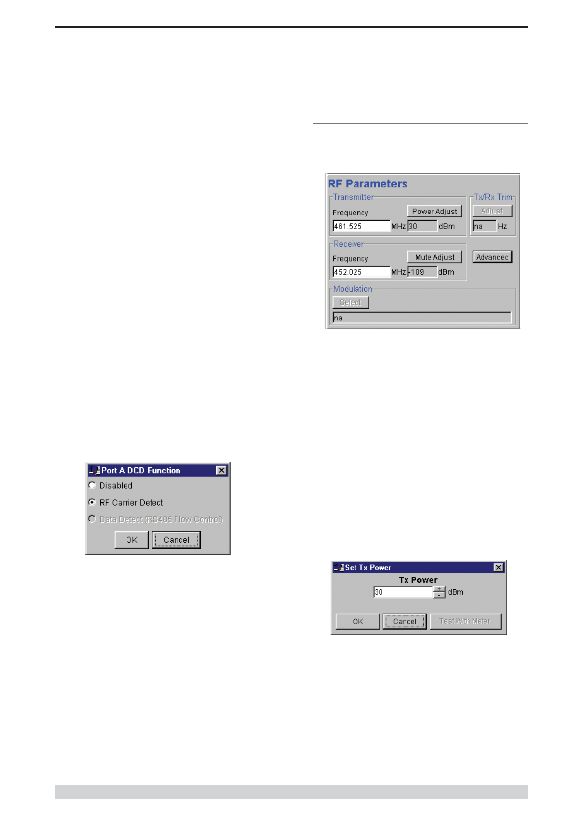
RF Parameters
This section of the main window permits adjustment of transmitter and
receiver, radio channel modulation scheme, frequency trim and
advanced features.
Transmitter
The transmitter can be configured for transmit frequency and power
level.
Frequency
The required transmit frequency in MHz can be entered in the display
field. The programmer checks that the selected frequency is in the
range for the particular model of radio and provides warnings if not.
Disabled
This selection disables the DCD output on the port. This selection is
not permissible if hardware based flow control has been selected.
RF Carrier Detect
This selection causes DCD to be asserted at the onset of a received
RF signal being detected. This will generally occur several
milliseconds before data is transmitted from the port.
Data Detect (RS485 Flow Control)
This selection causes DCD to be asserted when data is about to be
transmitted from the port. This option is not available if handshaking is
set to “None” or “Xon/Xoff”.
Power Adjust
The currently selected transmit power is displayed below the button in
dBm. The power level can be adjusted by selecting this button which
displays a dialogue box. The up/down keys, or a typed in value, can
be used to select the required power level in dBm steps. There are
two methods for setting the power.
Page 46
© Copyright 2002 Trio DataCom Pty . Ltd.
 Loading...