

Schneider Electric France L Isle d Espagnac XGCS85 User Manual

RFID OsiSense® XG
EIO0000001601 Draft 20 13/07/17
RFID OsiSense® XG
DI[D-SE-0029826.1.6]
®
RFID OsiSense
EtherNet/IP Smart Antenna
User Manual
Draft 2013/07/17
XG
www.schneider-electric.com
EIO0000001601.00

DI[D-SE-0029826.1.6]
The information provided in this documentation contains general descriptions and/or technical
characteristics of the performance of the products contained herein. This documentation is not
intended as a substitute for and is not to be used for determining suitability or reliability of these
products for specific user applications. It is the duty of any such user or integrator to perform the
appropriate and complete risk analysis, evaluation and testing of the products with respect to the
relevant specific application or use thereof. Neither Schneider Electric nor any of its affiliates or
subsidiaries shall be responsible or liable for misuse of the information contained herein. If you
have any suggestions for improvements or amendments or have found errors in this publication,
please notify us.
No part of this document may be reproduced in any form or by any means, electronic or
mechanical, including photocopying, without express written permission of Schneider Electric.
All pertinent state, regional, and local safety regulations must be observed when installing and
using this product. For reasons of safety and to help ensure compliance with documented system
data, only the manufacturer should perform repairs to components.
When devices are used for applications with technical safety requirements, the relevant
instructions must be followed.
Failure to use Schneider Electric software or approved software with our hardware products may
result in injury, harm, or improper operating results.
Failure to observe this information can result in injury or equipment damage.
© 2013 Schneider Electric. All rights reserved.
2 EIO0000001601 Draft 2013/07/17

DI[D-SE-0029826.1.6]
Table of Contents
Chapter 1 General Information . . . . . . . . . . . . . . . . . . . . . . . . . . . . 9
Chapter 2 Specifications and Physical Description . . . . . . . . . . . 19
Chapter 3 Installing the System . . . . . . . . . . . . . . . . . . . . . . . . . . . 33
Chapter 4 Operating Principles . . . . . . . . . . . . . . . . . . . . . . . . . . . 43
Chapter 5 EtherNet/IP Communications Support . . . . . . . . . . . . . 61
Safety Information . . . . . . . . . . . . . . . . . . . . . . . . . . . . . 5
About the Book. . . . . . . . . . . . . . . . . . . . . . . . . . . . . . . . 7
System Presentation . . . . . . . . . . . . . . . . . . . . . . . . . . . . . . . . . . . . . .
Exchange Principle . . . . . . . . . . . . . . . . . . . . . . . . . . . . . . . . . . . . . . .
Overview of the OsiSense XG Range . . . . . . . . . . . . . . . . . . . . . . . . .
System View . . . . . . . . . . . . . . . . . . . . . . . . . . . . . . . . . . . . . . . . . . . .
Smart Antenna Characteristics . . . . . . . . . . . . . . . . . . . . . . . . . . . . . .
Tags Characteristics . . . . . . . . . . . . . . . . . . . . . . . . . . . . . . . . . . . . . .
Description of the Smart Antenna . . . . . . . . . . . . . . . . . . . . . . . . . . . .
Connecting the OsiSense XG Smart Antenna. . . . . . . . . . . . . . . . . . .
Wiring Accessories . . . . . . . . . . . . . . . . . . . . . . . . . . . . . . . . . . . . . . .
Smart Antennas Wiring Example. . . . . . . . . . . . . . . . . . . . . . . . . . . . .
Installation Precautions . . . . . . . . . . . . . . . . . . . . . . . . . . . . . . . . . . . .
IP Address Configuration. . . . . . . . . . . . . . . . . . . . . . . . . . . . . . . . . . .
Read/Write Operating Mode . . . . . . . . . . . . . . . . . . . . . . . . . . . . . . . .
Memory Zones. . . . . . . . . . . . . . . . . . . . . . . . . . . . . . . . . . . . . . . . . . .
Smart Antenna System Memory Zone . . . . . . . . . . . . . . . . . . . . . . . .
Smart Antenna Command/Instructions Memory Zone . . . . . . . . . . . .
5.1 Object Model . . . . . . . . . . . . . . . . . . . . . . . . . . . . . . . . . . . . . . . . . . . .
About the Object Model . . . . . . . . . . . . . . . . . . . . . . . . . . . . . . . . . . . .
Assembly Object (Class ID 4) . . . . . . . . . . . . . . . . . . . . . . . . . . . . . . .
Modbus Object (Class ID 0x44). . . . . . . . . . . . . . . . . . . . . . . . . . . . . .
5.2 Unity Pro: EtherNet/IP Application Example . . . . . . . . . . . . . . . . . . . .
Presentation . . . . . . . . . . . . . . . . . . . . . . . . . . . . . . . . . . . . . . . . . . . .
Creating a Project . . . . . . . . . . . . . . . . . . . . . . . . . . . . . . . . . . . . . . . .
Configuring the TSXETC101 EtherNet/IP Communication Module. . .
Configuring the Ethernet Smart Antenna. . . . . . . . . . . . . . . . . . . . . . .
Read Application Example . . . . . . . . . . . . . . . . . . . . . . . . . . . . . . . . .
10
12
14
15
20
23
27
29
30
32
34
40
44
48
49
51
62
63
65
67
69
70
71
72
75
80
EIO0000001601 Draft 2013/07/17 3

DI[D-SE-0029826.1.6]
5.3 RSLogix: EtherNet/IP Application Example . . . . . . . . . . . . . . . . . . . . .
Configuring a Smart Antenna on an EtherNet/IP Network with a
ControlLogix PLC . . . . . . . . . . . . . . . . . . . . . . . . . . . . . . . . . . . . . . . . .
Read the Assembly 102 (General Status) or 103 (Read Table) Using
an Explicit Message . . . . . . . . . . . . . . . . . . . . . . . . . . . . . . . . . . . . . . .
Reading/Writing Request with the Modbus Object. . . . . . . . . . . . . . . .
82
83
90
94
Chapter 6 Modbus TCP/IP Communications Support . . . . . . . . . 101
Modbus Commands Supported by the Smart Antenna . . . . . . . . . . . .
Modbus Requests Description . . . . . . . . . . . . . . . . . . . . . . . . . . . . . . .
Modbus Application Example. . . . . . . . . . . . . . . . . . . . . . . . . . . . . . . .
102
107
111
Chapter 7 Web Server . . . . . . . . . . . . . . . . . . . . . . . . . . . . . . . . . . . 115
Web Server Access . . . . . . . . . . . . . . . . . . . . . . . . . . . . . . . . . . . . . . .
Setup Pages. . . . . . . . . . . . . . . . . . . . . . . . . . . . . . . . . . . . . . . . . . . . .
Documentation Web Page . . . . . . . . . . . . . . . . . . . . . . . . . . . . . . . . . .
116
118
123
Chapter 8 Diagnostics. . . . . . . . . . . . . . . . . . . . . . . . . . . . . . . . . . . 125
Smart Antenna Diagnostic LEDs . . . . . . . . . . . . . . . . . . . . . . . . . . . . .
Diagnostic Web Pages. . . . . . . . . . . . . . . . . . . . . . . . . . . . . . . . . . . . .
Ethernet TCP/IP Statistics Page . . . . . . . . . . . . . . . . . . . . . . . . . . . . .
Ethernet Port Statistics Page . . . . . . . . . . . . . . . . . . . . . . . . . . . . . . . .
Modbus TCP Port Statistics Page . . . . . . . . . . . . . . . . . . . . . . . . . . . .
Modbus TCP Messaging Statistics Page. . . . . . . . . . . . . . . . . . . . . . .
SNMP Statistics Page . . . . . . . . . . . . . . . . . . . . . . . . . . . . . . . . . . . . .
Diagnostic Log Page . . . . . . . . . . . . . . . . . . . . . . . . . . . . . . . . . . . . . .
Reader Diagnostics Page . . . . . . . . . . . . . . . . . . . . . . . . . . . . . . . . . .
126
128
129
130
131
132
133
134
135
Chapter 9 FAQs . . . . . . . . . . . . . . . . . . . . . . . . . . . . . . . . . . . . . . . . 137
FAQ . . . . . . . . . . . . . . . . . . . . . . . . . . . . . . . . . . . . . . . . . . . . . . . . . . .
Glossary . . . . . . . . . . . . . . . . . . . . . . . . . . . . . . . . . . . . . . . . .
Index . . . . . . . . . . . . . . . . . . . . . . . . . . . . . . . . . . . . . . . . .
137
143
149
4 EIO0000001601 Draft 2013/07/17
Safety Information
DI[D-NA-0003897.18.1]
Safety Information
Important Information
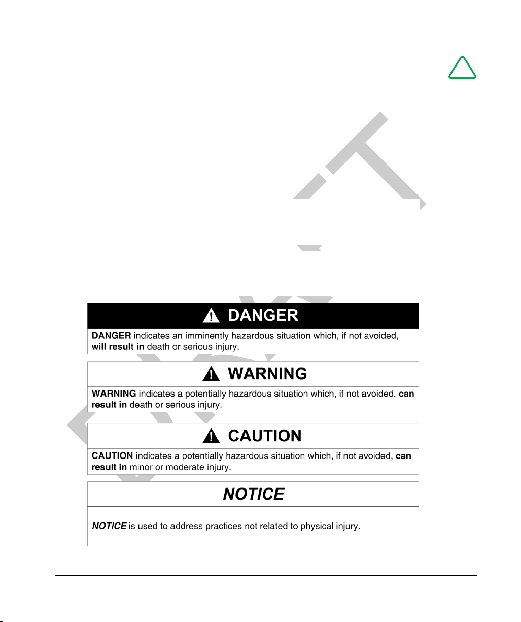
NOTICE
Read these instructions carefully, and look at the equipment to become familiar with the device
before trying to install, operate, or maintain it. The following special messages may appear
throughout this documentation or on the equipment to warn of potential hazards or to call attention
to information that clarifies or simplifies a procedure.
!
EIO0000001601 Draft 2013/07/17 5

PLEASE NOTE
Electrical equipment should be installed, operated, serviced, and maintained only by qualified
personnel. No responsibility is assumed by Schneider Electric for any consequences arising out of
the use of this material.
A qualified person is one who has skills and knowledge related to the construction and operation
of electrical equipment and its installation, and has received safety training to recognize and avoid
the hazards involved.
DI[D-NA-0003897.18.1]
6 EIO0000001601 Draft 2013/07/17

About the Book
DI[D-NA-0003897.18.1]
About the Book
At a Glance
Document Scope
This guide describes how to use OsiSense XG Smart Antenna and associated accessories.
Validity Note
This document is applicable to OsiSense XG Smart Antenna, version X.X.
The technical characteristics of the devices described in this manual also appear online. To access
this information online:
Step Action
1 Go to the Telemecanique Sensors home page www.tesensors.com.
2In the Search box type the model number of a product or the name of a product
3 If you entered a model number, go to the Product datasheets search results and
4 If more than one model number appears in the Products search results, click on
5 Depending on the size of your screen, you may need to scroll down to see the data
6 To save or print a data sheet as a .pdf file, click Download XXX product
range.
” Do not include blank spaces in the model number/product range.
” To get information on a grouping similar modules, use asterisks (*).
click on the model number that interests you.
If you entered the name of a product range, go to the Product Ranges search
results and click on the product range that interests you
the model number that interests you.
sheet.
datasheet.
The characteristics that are presented in this manual should be the same as those characteristics
that appear online. In line with our policy of constant improvement, we may revise content over time
to improve clarity and accuracy. If you see a difference between the manual and online information,
use the online information as your reference.
EIO0000001601 Draft 2013/07/17 7

Product Related Information
UNINTENDED EQUIPMENT OPERATION
The application of this product requires expertise in the design and programming of control
systems. Only persons with such expertise must be allowed to program, install, alter, and apply
this product.
Follow all local and national safety codes and standards.
Failure to follow these instructions can result in injury or equipment damage.
User Comments
We welcome your comments about this document. You can reach us by e-mail at customersupport@tesensors.com.
DI[D-NA-0003897.18.1]
CAUTION
8 EIO0000001601 Draft 2013/07/17

RFID OsiSense® XG
General Information
EIO0000001601 Draft 2013/07/17
DI[D-SE-0029830.1.1]
General Information
Chapter 1
General Information
General Information
Aim of this Chapter
This chapter presents the OsiSense XG Smart Antenna and the associated range of equipment.
What Is in This Chapter?
This chapter contains the following topics:
System Presentation 10
Exchange Principle 12
Overview of the OsiSense XG Range 14
System View 15
Topic Page
EIO0000001601 Draft 2013/07/17 9

General Information DI[D-SE-0029833.1.3]
System Presentation
System Presentation
Smart Antenna Presentation
The Smart Antenna is a compact RFID station offering the following advantages:
” 2 Ethernet ports
” An embedded web server allowing:
” Setup
” Diagnostic
” Monitoring
” Daisy chaining up to 32 Smart Antennas
” Compatible with most 13.56 MHz tags on the market.
Definition of RFID
RFID is the use of radio transmission to identify and locate objects.
An RFID system is based on 3 main components:
” A reader (Read/Write station)
” A radio antenna
” An electronic tag
Operation of an RFID System
The tag is attached on, or in, the object to be tracked or identified. There is no contact with the
reader. This means that the tag can be placed inside objects (boxes, bags, and so on...) and that
the reader can be positioned behind a protective screen, as long as the materials are not metallic.
When a tag enters the field generated by the reader, it detects the signal and exchanges the data
(read or write) between its memory and the reader.
Presentation of the Offer OsiSense XG
OsiSense XG is an RFID system offering:
” Traceability and tracking of items
” Flexibility of production systems
” Various types of access control
An open system:
” System compatible with tags that comply with standards ISO 14443 and ISO 15693
” Modbus, Modbus TCP/IP, EtherNet/IP, PROFIBUS DP, and Uni-Telway protocols
A simple system:
” No station programming
” Data formatted in accordance with PLC standards (16-bit words)
10 EIO0000001601 Draft 2013/07/17

DI[D-SE-0029833.1.3] General Information
” Automatic configuration of communication parameters (speed, format, and so on...)
” Quick wiring using M12 connectors
” Extensive range of cables and mounting accessories
” Possibility of using metal supports
Integrated system:
” Reader, radio antenna, and network functionalities in one device
” The smallest industrial RFID reader
EIO0000001601 Draft 2013/07/17 11

General Information DI[D-SE-0029834.1.7]
Exchange Principle
Exchange Principle
Presentation
The OsiSense XG Smart Antenna is used to send information from the tag to the PLC and vice
versa, as described below:
1 PLC
2 Smart Antenna
3 Tag
Phases in the Process
The table shows the various exchange phases:
Phase Exchanges
PLC Smart Antenna Smart Antenna Tag
1 Look for a tag in the dialog zone
2 Positive response
3 Send a read/write command
4 Execution of the command (with checks)
12 EIO0000001601 Draft 2013/07/17

DI[D-SE-0029834.1.7] General Information
Phase Exchanges
PLC Smart Antenna Smart Antenna Tag
5 Send back report
NOTE:
” If phase 3 is carried out with no tag present, a detected error message is sent back to the PLC.
” If a detected error occurs in phase 4, this phase is automatically restarted (up to 3 times). If a
detected error is still detected at the end of phase 4, a detected error report is sent back in phase
5.
EIO0000001601 Draft 2013/07/17 13

General Information DI[D-SE-0029835.1.3]
Overview of the OsiSense XG Range
Overview of the OsiSense XG Range
Introduction
The figure illustrates the OsiSense XG range.
14 EIO0000001601 Draft 2013/07/17

DI[D-SE-0029981.1.6] General Information
System View
System View
Description
OsiSense XG Smart Antenna can be used with a protocol compliant scanner as part of control
system architecture. The built-in unmanaged 2-port Ethernet switch of the Smart Antenna allows
you to use the network topology that meets your application needs. These topologies include the
following:
” star
” daisy-chain
” ring (daisy-chain with loopback)
” combination of star and daisy-chain
Star
Star topology allows you to connect additional network equip
one module—for example, by removing the network cable, or by cycling power to the module—
does not affect other modules.
ment. Performing maintenance on
1 Quantum PLC
2 Ethernet switch
3 Advantys STB Island
4 Magelis HMI device
5 OsiSense XG Smart Antenna
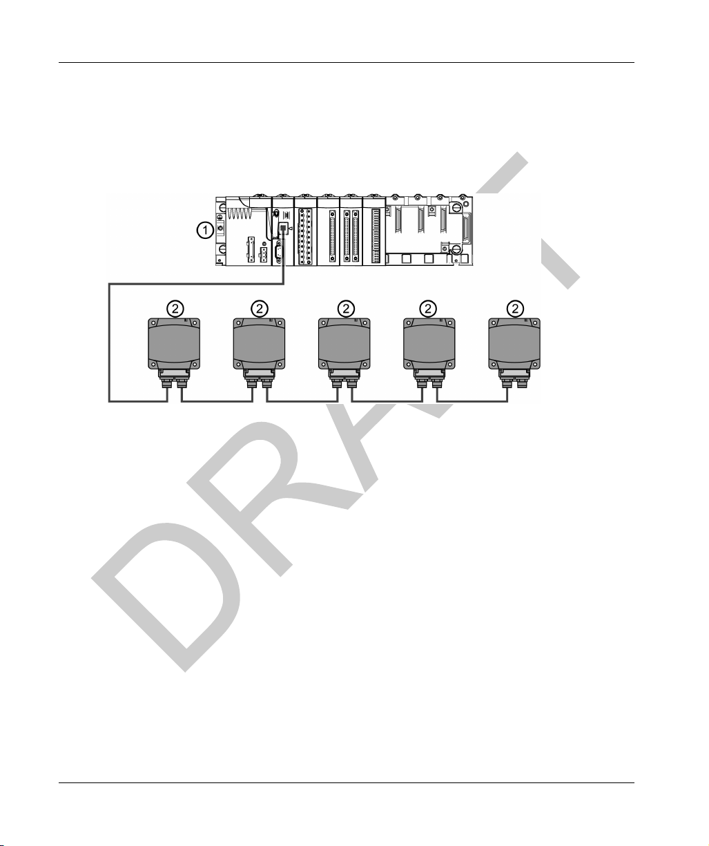
Daisy-Chain
You can create a daisy-chain topology by using the embedded switch
ports to connect a series of
up to 32 OsiSense XG Smart Antennas.
NOTE:
EIO0000001601 Draft 2013/07/17 15
General Information DI[D-SE-0029981.1.6]
When considering the daisy chain topology, note that:
” Performing maintenance on any module not physically located at the end of the daisy chain—
for example, by removing the network cable, or by cycling power to the module—affects any
modules located down the chain from the maintained module.
” The embedded dual port Ethernet switch located in each module eliminates the need for
additional Ethernet switches.
1 M340 PLC
2 Ethernet switch
3 OsiSense XG Smart Antenna
Ring
You can create a ring topology by using a switch with redundancy management protocol (for
example ConneXium TCSESM043F23F0).
You can connect a series of up to 32 OsiSense XG Smart Antennas.
NOTE:
When considering the ring topology, note that:
” If a network segment becomes inoperable or is cut, all Smart Antennas remain operational.
16 EIO0000001601 Draft 2013/07/17

DI[D-SE-0029981.1.6] General Information
1 Premium PLC
2 Ethernet switch with loopback function
3 OsiSense XG Smart Antenna
The table shows the ConneXium switches with redundancy function compatible with Smart
Antennas:
Reference Description
TCSESB083F23F0 8 port basic managed switch 8TX
TCSESB083F2CU0 8 port basic managed switch 6TX – 2FX multi mode
TCSESB093F2CU0 9 port basic managed switch 6TX – 3FX multi mode
TCSESM043F1CS0 4 port managed switch 3TX – 1FX single mode
TCSESM043F1CU0 4 port managed switch 3TX – 1FX multi mode
TCSESM043F23F0 4 port managed switch 4TX
TCSESM043F2CS0 4 port managed switch 2TX – 2FX single mode
TCSESM043F2CU0 4 port managed switch 2TX – 2FX multi mode
TCSESM083F1CS0 8 port managed switch 7TX – 1FX single mode
TCSESM083F1CU0 8 port managed switch 7TX – 1FX multi mode
TCSESM083F23F0 8 port managed switch 8TX
TCSESM083F2CS0 8 port managed switch 6TX – 2FX single mode
TCSESM083F2CU0 8 port managed switch 6TX – 2FX multi mode
TCSESM103F23G0 10 port managed switch 8TX/2TX-GBIT
TCSESM103F2LG0 10 port managed switch 8TX/2SFP-GBIT
EIO0000001601 Draft 2013/07/17 17

General Information DI[D-SE-0029981.1.6]
Reference Description
TCSESM163F23F0 16 port managed switch 16TX
TCSESM163F2CU0 16 port managed switch 14TX – 2FX multi mode
TCSESM163F2CS0 16 port managed switch 14TX – 2FX single mode
TCSESM243F2CU0 24 port managed switch 22TX – 2FX multi mode
TCSESM083F23F1 8 port extended managed switch 8TX
TCSESM063F2CS1 8 port extended managed switch 6TX – 2FX single mode
TCSESM063F2CU1 8 port extended managed switch 6TX – 2FX multi mode
18 EIO0000001601 Draft 2013/07/17

RFID OsiSense® XG
Specifications and Phys ical Description
EIO0000001601 Draft 2013/07/17
DI[D-SE-0029847.1.1]
Specifications and Phys ical Description
Chapter 2
Specifications and Physical Description
Specifications and Physical Description
Aim of this Chapter
This chapter presents the specifications and the physical description of the OsiSense XG Smart
Antenna.
What Is in This Chapter?
This chapter contains the following topics:
Smart Antenna Characteristics 20
Tags Characteristics 23
Description of the Smart Antenna 27
Connecting the OsiSense XG Smart Antenna 29
Wiring Accessories 30
Smart Antennas Wiring Example 32
Topic Page
EIO0000001601 Draft 2013/07/17 19

Specifications and Physical Description DI[D-SE-0029851.1.7]
Smart Antenna Characteristics
Smart Antenna Characteristics
Characteristics
The table gives the technical characteristics of the Smart Antenna:
Characteristic Description
Temperature Operation –25...+70 °C (–13...+158°F)
Storage –40...+85 °C (–40...+185°F)
Degree of protection IP65 according to IEC60529
Vibration resistance
EN 60068.2.27
EN 60068.2.6
Resistance to mechanical shocks IK02 according to EN 50102
Standards/Certifications UL 508, CE, EN 300330, EN 301489-01/03
Immunity to disturbances Immunity to electrostatic discharges, radiated electromagnetic fields, fast
Unit dimensions 80x93x40 mm (3.15x3.66x1.57 in)
RFID frequency 13.56 MHz
Type of associated tag Standardized ISO 15693 and ISO 14443 tags
Nominal range 20...100 mm (0.78...3.94 in) depending on associated tag
Power supply 24 Vdc PELV
Power supply voltage limits 19.2...29 V including ripple
Power consumption < 150 mA
Communication Interface Ethernet dual port 10 BASE-T/100 BASE-TX
Connection 2 M12 D coded female sockets for chaining
Display - 2 dual color LED for RFID communication
Tightening torque for the mounting
screws
2 mm (0.078 in) from 5 to 29.5 Hz / 7 g (7 gn)from 29.5 to 150 Hz
30 g (30 gn) / 11 ms
transients, electrical surges, conducted and induced interference and power
frequency magnetic field according to IEC61000/EN 55022
Automatic detection of the tag type
Connection on M8 4 pins male socket
- 4 dual color LED for Ethernet communication
< 3.6 Nm (31.9 lbf-in)
WARNING TO USERS IN THE UNITED STATES AND CANADA
WARNING TO USERS IN THE UNITED STATES
Federal Communication Commission Interference Statement
47 CFR Section 15.105(b)
20 EIO0000001601 Draft 2013/07/17

DI[D-SE-0029851.1.7] Specifications and Physical Description
This equipment has been tested and found to comply with the limits for a Class B digital device,
pursuant to Part 15 of the FCC Rules. These limits are designed to provide reasonable protection
against harmful interference in a residential installation. This equipment generates uses and can
radiate radio frequency energy and, if not installed and used in accordance with the instructions,
may cause harmful interference to radio communications. However, there is no guarantee that
interference will not occur in a particular installation.
If this equipment does cause harmful interference to radio or television reception, which can be
determined by turning the equipment off and on, the user is encouraged to try to correct the
interference by one of the following measures:
” Reorient or relocate the receiving antenna.
” Increase the separation between the equipment and receiver.
” Connect the equipment into an outlet on a circuit different from that to which the receiver is
connected.
” Consult the dealer or an experienced radio/TV technician for help.
This device Equipment name complies with Part 15 of the FCC Rules. Operation is subject to the
following two conditions:
1. This device may not cause harmful interference.
2. This device must accept any interference received, including interference that may cause
undesired operation.
NO UNAUTHORIZED MODIFICATIONS
47 CFR Section 15.21
CAUTION: This equipment may not be modified, altered, or changed in any way without signed
written permission from SCHNEIDER ELECTRIC. Unauthorized modification may void the
equipment authorization from the FCC and will void the SCHNEIDER ELECTRIC warranty.
WARNING TO USERS IN THE CANADA / ATTENTION POUR LES UTILISATEURS AU
CANADA
This device complies with Industry Canada licence-exempt RSS standard(s). Operation is subject
to the following two conditions:
1. this device may not cause interference, and
2. this device must accept any interference received, including interference that may cause
undesired operation of the device.
Under Industry Canada regulations, this radio transmitter may only operate using an antenna of a
type and maximum (or lesser) gain approved for the transmitter by Industry Canada. To reduce
potential radio interference to other users, the antenna type and its gain should be so chosen that
the equivalent isotropically radiated power (e.i.r.p.) is not more than that necessary for successful
communication.
Le présent appareil est conforme aux CNR d’Industrie Canada applicables aux appareils radio
exempts de licence. L’exploitation est autorisée aux deux conditions suivantes :
1. il ne doit pas produire de brouillage, et
2. l’utilisateur du dispositif doit être prêt a accepter tout brouillage radioélectrique reçu, même si
ce brouillage est susceptible de compromettre le fonctionnement du dispositif.
EIO0000001601 Draft 2013/07/17 21

Specifications and Physical Description DI[D-SE-0029851.1.7]
Conformément à la réglementation d’Industrie Canada, le présent émetteur radio peut fonctionner
avec une antenne d’un type et d’un gain maximal (ou inférieur) approuvé pour l’émetteur par
Industrie Canada. Dans le but de réduire les risques de brouillage radioélectrique à l’ intention
d’autres utilisateurs, il faut choisir le type d’antenne et son gain de sorte que la puissance isotrope
rayonnée équivalente (p.i.r.e.) ne dépasse pas l’intensité nécessaire à l’établissement d’une
communication satisfaisante.
References:
Reference XGCS850C201
FCC ID Y7HXGCS85
IC info 7002C-XGCS85
22 EIO0000001601 Draft 2013/07/17

DI[D-SE-0029867.1.12] Specifications and Physical Description
Tags Characteristics
Tags Characteristics
Tag Characteristics
The table gives the technical characteristics of the tags with EEPROM memory:
Type of Tag XGHB445345XGHB444345XGHB320345XGHB221346XGHB211345XGHB90E340
Operation
temperature
Storage
temperature
–25...+70 °C
(–13...+158°F)
–40...+85 °C
(–40...+185°F)
–25...+55 °C
(–13...+131°F)
–40...+55 °C
(–40...+131°F)
Degree of protection IP68 IP65 IP68 IP65
Standards
ISO 14443 ISO 15693
supported
Vibration resistance
EN 60068.2.27
EN 60068.2.6
Resistance to
2 mm (0.078 in) from 5 to 29.5 Hz / 7 g (7 gn)from 29.5 to 150 Hz
30 g (30 gn) / 11 ms
IK02 according to EN 50102
mechanical shocks
Dimensions 40x40x15 mm
(1.57x1.57x0.59 in)
∅ 30x3 mm
(1.18x0.12 in)
26x26x13
mm
(1.02x1.02x0.
∅ 18 mm
(0.70 in)
58x85.5x1 mm
(2.28x3.34x0.0
39 in)
51 in)
Casing materials PBT PC PBT PVC
Mounting method Screw or clip Screw Screw or clip Threaded
-
hole
Tightening torque for
< 1 Nm (8.85 lbf-in) --
the mounting screws
Memory capacity
13 632 3 408 112 256 256 256
(bytes)
Type of memory EEPROM
Type of operation Read/Write
Nominal range
(Read/Write)
Number of read
40 mm
(1.57 in)
Unlimited
48 mm
(1.89 in)
65 mm
(2.56 in)
55 mm
(2.16 in)
20 mm
(0.78 in)
100 mm
(3.94 in)
cycles
Number of write
100000 provided over the entire temperature range
cycles
Number of write
2.5 million typical cases
cycles at 30 °C
(86°F)
EIO0000001601 Draft 2013/07/17 23

Specifications and Physical Description DI[D-SE-0029867.1.12]
Type of Tag XGHB445345XGHB444345XGHB320345XGHB221346XGHB211345XGHB90E340
Read/Write time Read/Write time (see page 25)
Retention period 10 years
The table gives the technical characteristics of the tags with FeRAM memory:
Type of Tag XGHB320246 XGH440245 XGH440845 XGHB443245
Temperature Operation –25...+70 °C
Storage –40...+85 °C
Degree of protection IP65 IP68
Standards supported ISO 15693 ISO 14443
Vibration resistance
EN 60068.2.27
EN 60068.2.6
Resistance to mechanical
shocks
Dimensions ∅ 30x3 mm
Casing materials PC PBT
Mounting method Screw Screw or clip
Tightening torque for the
mounting screws
Memory capacity (bytes) 2 000 2 000 8 192 32 768
Type of memory FeRAM
Type of operation Read/Write
Nominal range (Read/Write) 65 mm (2.56 in) 39 mm (1.53 in)
Number of read cycles Unlimited
Number of write cycles
Read/Write time Read/Write time (
R
etention period 10 years
(–13...+158°F)
(–40...+185°F)
2 mm (0.078 in) from 5 to 29.5 Hz / 7 g (7 gn)from 29.5 to 150 Hz
30 g (30 gn) / 11 ms
IK02 according to EN 50102
40x40x15 mm (1.57x1.57x0.59 in)
(1.18x0.12 in)
< 1 Nm (8.85 lbf-in)
1010 provided over the entire temperature range
see page 25)
Tag Memory Zone
These tags are addressed according to the table below and are accessible in Read/Write mode.
24 EIO0000001601 Draft 2013/07/17

DI[D-SE-0029867.1.12] Specifications and Physical Description
The Smart Antenna can read any tag in the XGHB range (automatic detection of the tag type).
Tag Reference Memory Size Range Addresses
Dec Hex
XGHB320345 112 bytes 0...55 0...37
XGHB90E340 256 bytes 0...127 0...7F
XGHB211345 256 bytes 0...127 0...7F
XGHB221346 256 bytes 0...127 0...7F
XGHB440245 2000 bytes 0...999 0...3E7
XGHB320246 2000 bytes 0...999 0...3E7
XGHB444345 3408 bytes 0...1703 0...6A7
XGHB440845 8192 bytes 0...4095 0...FFF
XGHB445345 13632 bytes 0...6815 0...1A9F
XGHB443245 32768 bytes 0...16383 0...3FFF
NOTE: If an address requested is out of the range address of the tag, a detected error code is
generated.
NOTICE
UNINTENDED OPERATION
Do not use in the same tag application XGHB445345 and XGHB444345.
Failure to follow these instructions can result in equipment damage.
NOTE: Once the Smart Antenna has auto-detected the XGHB445345 tag, it will no longer
recognize the XGHB444345 tag.
Read/Write Time and Tags Maximum Speed
The table shows the calculation of read/write time in static, and the tags maximum speed in
dynamic:
Tag Reference Static Dynamic
Access Time Calculation Tag Maximum Speed (m/s)
Read Time (ms) Write Time (ms) Read a Serial
Number
XGHB320345 12 + 0.825 x N 12 + 5.6 x N 5.8 2.7 0.9
XGHB90E340 12 + 0.825 x N 20 + 11.8 x N 7.1 4.0 0.8
XGHB211345 12 + 0.825 x N 19 + 4.1 x N 3.2 1.1 0.6
EIO0000001601 Draft 2013/07/17 25
Read a Word* Read or Write
10 Words*

Specifications and Physical Description DI[D-SE-0029867.1.12]
Tag Reference Static Dynamic
Access Time Calculation Tag Maximum Speed (m/s)
Read Time (ms) Write Time (ms) Read a Serial
Number
XGHB221346 12 + 0.825 x N 20 + 11.8 x N 4.2 2.6 0.5
XGHB440245 7 + 2 x N 7 + 2.4 x N 3.5 2.5 1
XGHB320246 7 + 2 x N 7 + 2.4 x N 3.5 2.5 1
XGHB444345 9.25 + 0.375 x N 13 + 0.8 x N 4.8 2.7 1.8
XGHB440845 6 + 0.25 x N 6 + 0.25 x N 3.8 3.0 2.6
XGHB445345 16.25 + 0.375 x N 20 + 0.8 x N 4.2 2.0 1.5
XGHB443245 6 + 0.25 x N 6 + 0.25 x N 3.8 3.0 2.6
Read a Word* Read or Write
10 Words*
N: Number of 16-bit words
*: with use of the “Auto read/write” function
26 EIO0000001601 Draft 2013/07/17

DI[D-SE-0029856.1.3] Specifications and Physical Description
Description of the Smart Antenna
Description of the Smart Antenna
Presentation of the Smart Antenna
The figure presents the Smart Antenna:
No. Description
1 TAG: Tag LED
2 COM: Communication LED
3 NS: Network Status LED
4 LK/SP: Ethernet communication port No. 1 LED
5 M12 socket, Ethernet port No. 1
6 M8 socket, 24 Vdc power supply
7 M12 socket, Ethernet port No. 2
8 LK/SP: Ethernet communication port No. 2 LED
9 MS : Ethernet Module Status LED
EIO0000001601 Draft 2013/07/17 27

Specifications and Physical Description DI[D-SE-0029856.1.3]
Dimensions
The figure shows the dimensions of the Smart Antenna:
28 EIO0000001601 Draft 2013/07/17

DI[D-SE-0029857.1.5] Specifications and Physical Description
Connecting the OsiSense XG Smart Antenna
Connecting the OsiSense XG Smart Antenna
Introduction
The Smart Antenna is equipped with:
” a male M8 connector for the power supply,
” 2 female M12 D-coded connectors for Ethernet communication.
Power Supply Wiring
The table describes the M8 connector pinout:
M8 Connector Pin No. Signal XZCP0941L• Wire Color
1
2 Not connected White
3
4 Not connected Black
+24 V
0V
NOTE: Use a PELV power supply and fuse protection (1 A). The power supply used must be class
II according to VDE 0106 (for example: Phaseo ABL 7/8 range of Schneider Electric). The 0 V must
be connected to the ground to increase EMC strength.
Brown
Blue
Communication Wiring
The table describes the M12 connectors pinout a
nd the correspondence with the RJ45 connector
of communication cables (seepage30):
M12 Connector M12 Pin Signal Description RJ45 Pin RJ45 Connector
1 TD+ Transmit Data + 1
2 RD+ Received Data + 2
3 TD– Transmit Data – 3
4 RD– Received Data – 6
- - Not connected 4
- - Not connected 6
- - Not connected 7
- - Not connected 8
EIO0000001601 Draft 2013/07/17 29

Specifications and Physical Description DI[D-SE-0030135.1.6]
Wiring Accessories
Wiring Accessories
Introduction
The range of accessories is composed of power supply cables, communication cables, and
Ethernet connection accessories.
Power Supply Cables
The table shows the range of power supply cables:
Description Length Reference
Pre-wired M8 connector 2 m (6.56 ft) XZCP0941L2
5m (16.4 ft) XZCP0941L5
10 m (32.8 ft) XZCP0941L10
Communication Cables
The table shows the range of communication cables:
Description End Fittings Length Reference
Copper connecting
cables, straight
Copper connecting
cables, elbowed
Ethernet copper cable (2 x
24 AWG shielded twisted
pairs)
RJ45 connector Conforms to EIA/TIA-568-D - TCSEK3MDS
M12 connector Conforms to IEC 60176-2-101 - TCSEK1MDRS
1 x IP67 M12 4-pin connector and 1 x
RJ45 connector
2 x IP67 M12 4-pin connectors 1 m (3.28 ft) XGSZ12E1201
1 x IP67 M12 4-pin elbowed connector
and 1 x RJ45 connector
Connectors to install 300 m (984.2 ft)* TCSECN300R2
1m (3.28 ft) XGSZ12E4501
3m (9.84 ft) XGSZ12E4503
10 m (32.8 ft) XGSZ12E4510
3m (9.84 ft) XGSZ12E1203
10 m (32.8 ft) XGSZ12E1210
25 m (82 ft) XGSZ12E1225
3m (9.84 ft) XGSZ22E4503
10 m (32.8 ft) XGSZ22E4510
* The maximum length of Ethernet connecting cables made up in this way is 80 m (262.5 ft).
30 EIO0000001601 Draft 2013/07/17
 Loading...