

Page 1
XPSUAT
EIO0000003443 11/2020
XPSUAT
Safety Module
Original instructions
11/2020
EIO0000003443.01
www.schneider-electric.com
Page 2

The information provided in this documentation contains general descriptions and/or technical characteristics of the performance of the products contained herein. This documentation is not intended as a
substitute for and is not to be used for determining suitability or reliability of these products for specific user
applications. It is the duty of any such user or integrator to perform the appropriate and complete risk
analysis, evaluation and testing of the products with respect to the relevant specific application or use
thereof. Neither Schneider Electric nor any of its affiliates or subsidiaries shall be responsible or liable for
misuse of the information contained herein. If you have any suggestions for improvements or amendments
or have found errors in this publication, please notify us.
You agree not to reproduce, other than for your own personal, noncommercial use, all or part of this
document on any medium whatsoever without permission of Schneider Electric, given in writing. You also
agree not to establish any hypertext links to this document or its content. Schneider Electric does not grant
any right or license for the personal and noncommercial use of the document or its content, except for a
non-exclusive license to consult it on an "as is" basis, at your own risk. All other rights are reserved.
All pertinent state, regional, and local safety regulations must be observed when installing and using this
product. For reasons of safety and to help ensure compliance with documented system data, only the
manufacturer should perform repairs to components.
When devices are used for applications with technical safety requirements, the relevant instructions must
be followed.
Failure to use Schneider Electric software or approved software with our hardware products may result in
injury, harm, or improper operating results.
Failure to observe this information can result in injury or equipment damage.
© 2020 Schneider Electric. All rights reserved.
2 EIO0000003443 11/2020
Page 3

Table of Contents
Safety Information. . . . . . . . . . . . . . . . . . . . . . . . . . . . . . . . . . . . . . . . . . . . 5
About the Book . . . . . . . . . . . . . . . . . . . . . . . . . . . . . . . . . . . . . . . . . . . . . . 7
Chapter 1 Introduction. . . . . . . . . . . . . . . . . . . . . . . . . . . . . . . . . . . . . . . . . . . . . . . . . 11
Device Overview . . . . . . . . . . . . . . . . . . . . . . . . . . . . . . . . . . . . . . . . . . . . . . . . . . . . . . . . . .
Front View and Side View . . . . . . . . . . . . . . . . . . . . . . . . . . . . . . . . . . . . . . . . . . . . . . . . . . .
Nameplate . . . . . . . . . . . . . . . . . . . . . . . . . . . . . . . . . . . . . . . . . . . . . . . . . . . . . . . . . . . . . . .
Type Code . . . . . . . . . . . . . . . . . . . . . . . . . . . . . . . . . . . . . . . . . . . . . . . . . . . . . . . . . . . . . . .
Chapter 2 Technical Data . . . . . . . . . . . . . . . . . . . . . . . . . . . . . . . . . . . . . . . . . . . . . . 17
Environmental Conditions . . . . . . . . . . . . . . . . . . . . . . . . . . . . . . . . . . . . . . . . . . . . . . . . . . .
Mechanical Characteristics . . . . . . . . . . . . . . . . . . . . . . . . . . . . . . . . . . . . . . . . . . . . . . . . . .
Electrical Characteristics . . . . . . . . . . . . . . . . . . . . . . . . . . . . . . . . . . . . . . . . . . . . . . . . . . . .
Timing Data . . . . . . . . . . . . . . . . . . . . . . . . . . . . . . . . . . . . . . . . . . . . . . . . . . . . . . . . . . . . . .
Data Functional Safety . . . . . . . . . . . . . . . . . . . . . . . . . . . . . . . . . . . . . . . . . . . . . . . . . . . . .
Chapter 3 Engineering. . . . . . . . . . . . . . . . . . . . . . . . . . . . . . . . . . . . . . . . . . . . . . . . . 29
Electromagnetic Compatibility (EMC) . . . . . . . . . . . . . . . . . . . . . . . . . . . . . . . . . . . . . . . . . .
Basic Principles of Operation . . . . . . . . . . . . . . . . . . . . . . . . . . . . . . . . . . . . . . . . . . . . . . . .
Safety-Related Inputs . . . . . . . . . . . . . . . . . . . . . . . . . . . . . . . . . . . . . . . . . . . . . . . . . . . . . .
Synchronization of Safety-Related Inputs . . . . . . . . . . . . . . . . . . . . . . . . . . . . . . . . . . . . . . .
Dynamization. . . . . . . . . . . . . . . . . . . . . . . . . . . . . . . . . . . . . . . . . . . . . . . . . . . . . . . . . . . . .
Signal Interlock Monitoring . . . . . . . . . . . . . . . . . . . . . . . . . . . . . . . . . . . . . . . . . . . . . . . . . .
Chapter 4 Installation. . . . . . . . . . . . . . . . . . . . . . . . . . . . . . . . . . . . . . . . . . . . . . . . . . 39
Prerequisites and Requirements . . . . . . . . . . . . . . . . . . . . . . . . . . . . . . . . . . . . . . . . . . . . . .
Mechanical Installation . . . . . . . . . . . . . . . . . . . . . . . . . . . . . . . . . . . . . . . . . . . . . . . . . . . . .
Electrical Installation . . . . . . . . . . . . . . . . . . . . . . . . . . . . . . . . . . . . . . . . . . . . . . . . . . . . . . .
Chapter 5 Functions . . . . . . . . . . . . . . . . . . . . . . . . . . . . . . . . . . . . . . . . . . . . . . . . . . 47
Application Functions . . . . . . . . . . . . . . . . . . . . . . . . . . . . . . . . . . . . . . . . . . . . . . . . . . . . . .
Start Functions . . . . . . . . . . . . . . . . . . . . . . . . . . . . . . . . . . . . . . . . . . . . . . . . . . . . . . . . . . .
Delay Function. . . . . . . . . . . . . . . . . . . . . . . . . . . . . . . . . . . . . . . . . . . . . . . . . . . . . . . . . . . .
Chapter 6 Configuration and Commissioning . . . . . . . . . . . . . . . . . . . . . . . . . . . . . . . 65
Configuration . . . . . . . . . . . . . . . . . . . . . . . . . . . . . . . . . . . . . . . . . . . . . . . . . . . . . . . . . . . . .
Commissioning . . . . . . . . . . . . . . . . . . . . . . . . . . . . . . . . . . . . . . . . . . . . . . . . . . . . . . . . . . .
Chapter 7 Diagnostics . . . . . . . . . . . . . . . . . . . . . . . . . . . . . . . . . . . . . . . . . . . . . . . . . 69
Diagnostics via LEDs. . . . . . . . . . . . . . . . . . . . . . . . . . . . . . . . . . . . . . . . . . . . . . . . . . . . . . .
Diagnostics via Status Output Z1 . . . . . . . . . . . . . . . . . . . . . . . . . . . . . . . . . . . . . . . . . . . . .
Chapter 8 Accessories, Service, Maintenance, and Disposal. . . . . . . . . . . . . . . . . . . 77
Accessories . . . . . . . . . . . . . . . . . . . . . . . . . . . . . . . . . . . . . . . . . . . . . . . . . . . . . . . . . . . . . .
Maintenance . . . . . . . . . . . . . . . . . . . . . . . . . . . . . . . . . . . . . . . . . . . . . . . . . . . . . . . . . . . . .
Transportation, Storage, and Disposal . . . . . . . . . . . . . . . . . . . . . . . . . . . . . . . . . . . . . . . . .
Service Addresses. . . . . . . . . . . . . . . . . . . . . . . . . . . . . . . . . . . . . . . . . . . . . . . . . . . . . . . . .
Index . . . . . . . . . . . . . . . . . . . . . . . . . . . . . . . . . . . . . . . . . . . . . . . . . . . . .
12
13
14
15
18
20
21
24
26
30
31
34
36
37
38
40
41
42
48
59
63
66
67
70
73
78
79
80
81
83
EIO0000003443 11/2020 3
Page 4

4 EIO0000003443 11/2020
Page 5
Safety Information
Important Information
NOTICE
Read these instructions carefully, and look at the equipment to become familiar with the device before
trying to install, operate, service, or maintain it. The following special messages may appear throughout
this documentation or on the equipment to warn of potential hazards or to call attention to information that
clarifies or simplifies a procedure.
PLEASE NOTE
Electrical equipment should be installed, operated, serviced, and maintained only by qualified personnel.
No responsibility is assumed by Schneider Electric for any consequences arising out of the use of this
material.
A qualified person is one who has skills and knowledge related to the construction and operation of
electrical equipment and its installation, and has received safety training to recognize and avoid the
hazards involved.
QUALIFICATION OF PERSONNEL
Only appropriately trained persons who are familiar with and understand the contents of this manual and
all other pertinent product documentation as well as all documentation of all components and equipment
of the machine/process are authorized to work on and with this product.
The qualified person must be a certified expert in safety engineering.
The qualified person must be able to detect possible hazards that may arise from parameterization,
modifying configurations, settings, and wiring, and generally from mechanical, electrical, or electronic
equipment. The qualified person must be able to understand the effects that modifications to
configurations, settings, and wiring may have on the safety of the machine/process.
EIO0000003443 11/2020 5
Page 6

INTENDED USE
The qualified person must be familiar with and understand the contents of the risk assessment as per ISO
12100-1 and/or any other equivalent assessment as well as all documents related to such risk assessment
or equivalent assessments for the machine/process.
The qualified person must be familiar with the standards, provisions, and regulations for the prevention of
industrial accidents, which they must observe when designing, implementing, and maintaining the
machine/process.
The qualified person must be thoroughly familiar with the safety-related applications and the non-safetyrelated applications used to operate the machine/process.
This product described in the present document is a safety module intended to perform safety-related
functions in a machine/process according to the present document, to the specified related documents,
and to all other documentation of the components and equipment of the machine/process.
The product may only be used in compliance with all applicable safety regulations and directives, the
specified requirements and the technical data.
Prior to using the product, you must perform a risk assessment as per ISO 12100-1 in view of the planned
application. Based on the results of the risk assessment, the appropriate safety-related measures must be
implemented.
Since the product is used as a component in an overall machine or process, you must ensure the safety
of persons by means of the design of this overall machine or process.
Operate the product only with the specified cables and accessories. Use only genuine accessories.
Any use other than the use explicitly permitted is prohibited and can result in hazards.
6 EIO0000003443 11/2020
Page 7

At a Glance
Document Scope
Validity Note
Related Documents
About the Book
This manual describes technical characteristics, installation, commissioning, operation and maintenance
of the safety module XPSUAT.
The present document is valid for the products listed in the type code
(see page 15)
For product compliance and environmental information (RoHS, REACH, PEP, EOLI, etc.), go to
www.schneider-electric.com/green-premium
.
The technical characteristics of the devices described in the present document also appear online. To
access the information online, go to the Schneider Electric home page
https://www.se.com/ww/en/download/
.
The characteristics that are described in the present document should be the same as those characteristics that appear online. In line with our policy of constant improvement, we may revise content over time
to improve clarity and accuracy. If you see a difference between the document and online information, use
the online information as your reference.
.
Title of documentation Reference number
XPSUAT User Guide EIO0000003443 (ENG)
EIO0000003444 (FRE)
EIO0000003445 (GER)
EIO0000003446 (ITA)
EIO0000003447 (SPA)
EIO0000003450 (CHS)
XPSUAT Instruction Sheet PHA71829 (ENG, FRE, GER,
ITA, SPA, CHS)
XPSUAT Instruction Sheet PHA71837 (ENG, JAP, KOR,
POR, RUS, TUR)
XPSUEP User Guide EIO0000003509 (ENG)
EIO0000003510 (FRE)
EIO0000003511 (GER)
EIO0000003512 (ITA)
EIO0000003513 (SPA)
EIO0000003516 (CHS)
XPSUEP Instruction Sheet PHA71854 (ENG, FRE, GER,
ITA, SPA, CHS)
XPSUEP Instruction Sheet PHA71855 (ENG, JAP, KOR,
POR, RUS, TUR)
PreventaSupport Library Guide EIO0000003835 (ENG)
You can download these technical publications and other technical information from our website at
www.schneider-electric.com/en/download
.
EIO0000003443 11/2020 7
Page 8
Product Related Information
HAZARD OF ELECTRIC SHOCK, EXPLOSION OR ARC FLASH
Disconnect all power from all equipment including connected devices prior to removing any covers or
doors, or installing or removing any accessories, hardware, cables, or wires except under the specific
conditions specified in the appropriate hardware guide for this equipment.
Always use a properly rated voltage sensing device to confirm the power is off where and when
indicated.
Where 24 Vdc or Vac is indicated, use PELV power supplies conforming to IEC 60204-1.
Replace and secure all covers, accessories, hardware, cables, and wires and confirm that a proper
ground connection exists before applying power to this equipment.
Use only the specified voltage when operating this equipment and any associated products.
Failure to follow these instructions will result in death or serious injury.
This equipment has been designed to operate outside of any hazardous location. Only install this
equipment in zones known to be free of a hazardous atmosphere.
POTENTIAL FOR EXPLOSION
Install and use this equipment in non-hazardous locations only.
Failure to follow these instructions will result in death or serious injury.
DANGER
DANGER
WARNING
LOSS OF CONTROL
The designer of any control scheme must consider the potential failure modes of control paths and,
for certain critical control functions, provide a means to achieve a safe state during and after a path
failure. Examples of critical control functions are emergency stop and overtravel stop, power outage
and restart.
Separate or redundant control paths must be provided for critical control functions.
System control paths may include communication links. Consideration must be given to the
implications of unanticipated transmission delays or failures of the link.
Observe all accident prevention regulations and local safety guidelines.
Each implementation of this equipment must be individually and thoroughly tested for proper operation
before being placed into service.
Failure to follow these instructions can result in death, serious injury, or equipment damage.
1
For additional information, refer to NEMA ICS 1.1 (latest edition), "Safety Guidelines for the Application,
Installation, and Maintenance of Solid State Control" and to NEMA ICS 7.1 (latest edition), "Safety
Standards for Construction and Guide for Selection, Installation and Operation of Adjustable-Speed Drive
Systems" or their equivalent governing your particular location.
1
8 EIO0000003443 11/2020
Page 9
INSUFFICIENT AND/OR INEFFECTIVE SAFETY-RELATED FUNCTIONS
Verify that a risk assessment as per ISO 12100 and/or other equivalent assessment has been
performed before this product is used.
Before performing any type of work on or with this product, fully read and understand all pertinent
manuals.
Verify that modifications do not compromise or reduce the Safety Integrity Level (SIL), Performance
Level (PL) and/or any other safety-related requirements and capabilities defined for your
machine/process.
After modifications of any type whatsoever, restart the machine/process and verify the correct
operation and effectiveness of all functions by performing comprehensive tests for all operating states,
the defined safe state, and all potential error situations.
Failure to follow these instructions can result in death, serious injury, or equipment damage.
Terminology Derived from Standards
The technical terms, terminology, symbols and the corresponding descriptions in this manual, or that
appear in or on the products themselves, are generally derived from the terms or definitions of international
standards.
In the area of functional safety systems, drives and general automation, this may include, but is not limited
to, terms such as
,
message
dangerous
Among others, these standards include:
Standard Description
IEC 61131-2:2007 Programmable controllers, part 2: Equipment requirements and tests.
ISO 13849-1:2015 Safety of machinery: Safety related parts of control systems.
EN 61496-1:2013 Safety of machinery: Electro-sensitive protective equipment.
ISO 12100:2010 Safety of machinery - General principles for design - Risk assessment and risk
EN 60204-1:2006 Safety of machinery - Electrical equipment of machines - Part 1: General
ISO 14119:2013 Safety of machinery - Interlocking devices associated with guards - Principles
ISO 13850:2015 Safety of machinery - Emergency stop - Principles for design
IEC 62061:2015 Safety of machinery - Functional safety of safety-related electrical, electronic,
IEC 61508-1:2010 Functional safety of electrical/electronic/programmable electronic safety-
IEC 61508-2:2010 Functional safety of electrical/electronic/programmable electronic safety-
IEC 61508-3:2010 Functional safety of electrical/electronic/programmable electronic safety-
IEC 61784-3:2016 Industrial communication networks - Profiles - Part 3: Functional safety
2006/42/EC Machinery Directive
2014/30/EU Electromagnetic Compatibility Directive
2014/35/EU Low Voltage Directive
WARNING
safety, safety function, safe state, fault, fault reset, malfunction, failure, error, error
, etc.
General principles for design.
Part 1: General requirements and tests.
reduction
requirements
for design and selection
and electronic programmable control systems
related systems: General requirements.
related systems: Requirements for electrical/electronic/programmable
electronic safety-related systems.
related systems: Software requirements.
fieldbuses - General rules and profile definitions.
In addition, terms used in the present document may tangentially be used as they are derived from other
standards such as:
Standard Description
IEC 60034 series Rotating electrical machines
IEC 61800 series Adjustable speed electrical power drive systems
EIO0000003443 11/2020 9
Page 10

Standard Description
IEC 61158 series Digital data communications for measurement and control – Fieldbus for use in
industrial control systems
Finally, the term
zone of operation
is defined as it is for a
ISO 12100:2010
.
hazard zone
may be used in conjunction with the description of specific hazards, and
or
danger zone
in the
Machinery Directive (2006/42/EC
) and
10 EIO0000003443 11/2020
Page 11

XPSUAT
Introduction
EIO0000003443 11/2020
Introduc tion
Chapter 1
Introduction
What Is in This Chapter?
This chapter contains the following topics:
Device Overview 12
Front View and Side View 13
Nameplate 14
Type Code 15
Topic Page
EIO0000003443 11/2020 11
Page 12

Introduction
Device Overview
Outline
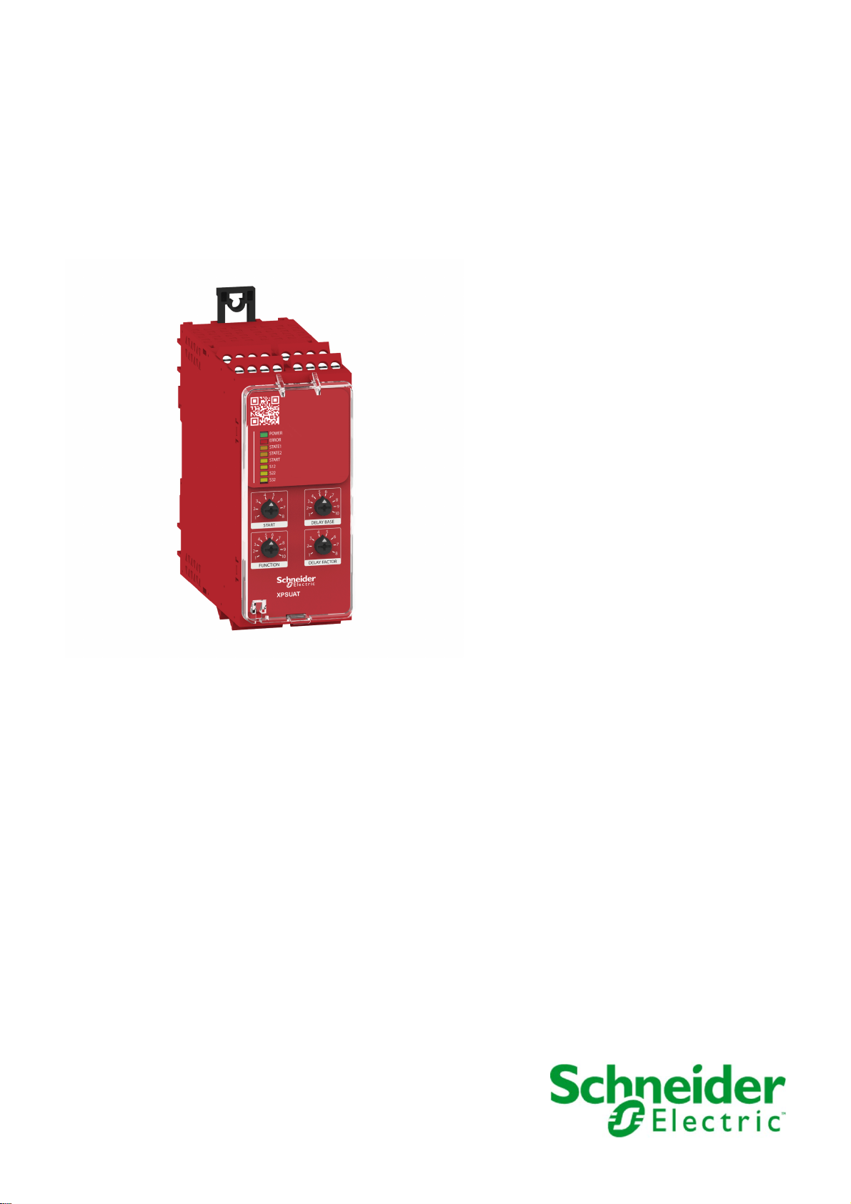
The device is a safety module for interruption of safety-related electrical circuits.
The device provides application functions used to monitor signals from different types of sensors/devices.
Equipment with the following types of outputs can be connected to the safety-related inputs of the device:
NO, NC, C/O, for example, Emergency Stop push-buttons, guard door switches, coded magnetic
switches
PNP, NPN transistors, for example, magnetic switches, proximity switches
OSSD, for example, light curtains
The device is available in four different types: either spring terminals or screw terminals and either
24 Vac/Vdc supply voltage or 48 … 240 Vac/Vdc supply voltage.
Feature summary:
10 application functions
Configurable start function
3 safety-related inputs
7 safety-related relay outputs
2 non-safety-related status/diagnostics outputs
1 non-safety-related start input with 8 selectable start functions
Connector for connection of extension module XPSUEP to increase the number of safety-related
outputs by 6
12
EIO0000003443 11/2020
Page 13
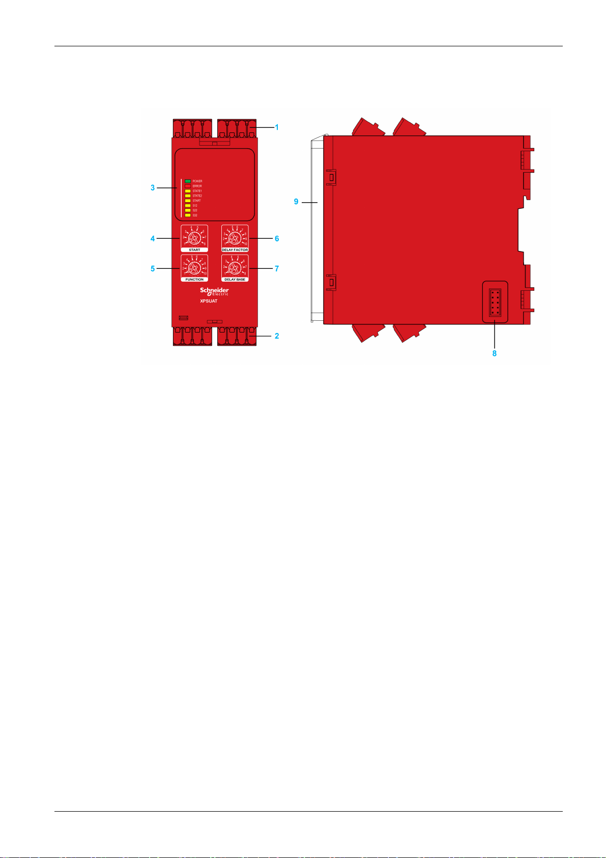
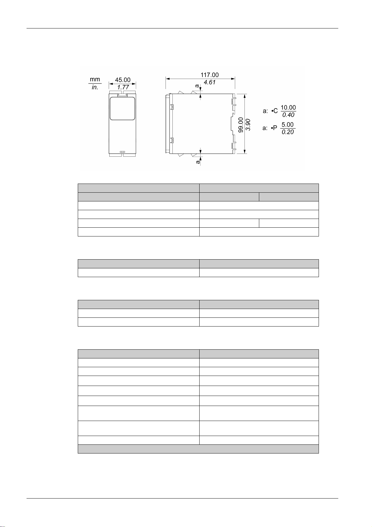
Front View and Side View
Front View and Side View
Introduction
1 Removable terminal blocks, top
2 Removable terminal blocks, bottom
3 LED indicators
4 Start function selector
5 Function selector
6 Delay factor selector
7 Delay base selector
8 Connector for optional output extension module XPSUEP (lateral)
9 Sealable transparent cover
EIO0000003443 11/2020 13
Page 14

Introduction
Nameplate
Nameplate
The nameplate contains the following data:
1 Device type (refer to chapter Type Code
(seepage15)
)
2 Nominal voltage
3 Frequency range Vac supply
4 Input power
5 Maximum current of safety-related outputs with utilization category AC15 (250 Vac)
6 Maximum current of safety-related outputs with utilization category DC13 (24 Vdc)
7 Maximum total thermal current
8 Maximum Safety Integrity Level (SIL) as per IEC 61508-1:2010
9 Maximum Performance Level and Category as per ISO 13849-1:2015
10 Maximum response time to request at safety-related input
11 Permissible ambient temperature range during operation
12 IP degree of protection
13 Serial number
14 Product version (PV), release (RL), software version (SV)
15 Plant code and date of manufacture (example: PP-2019-W10 means plant code PP, year of
manufacture 2019, week of manufacture 10)
14
EIO0000003443 11/2020
Page 15
Type Code
Type Code
Introduction
Item 1 2 3 4 5 6 7 8 9 10 11 12
Type code (example) X P S U A T 1 3 A 3 A C
Item Meaning
1 ... 4 Product range
XPSU = Universal
5 ... 6 Product version
AT
7 Supply voltage
1 = 24 Vac/Vdc
3 = 48 … 240 Vac/Vdc
8 ... 11 Number of safety-related outputs
3A3A = 3 normally open relay contacts, instantaneous, 3 normally open relay
contacts, delayed
12 Terminal type
C = Spring terminals, removable
P = Screw terminals, removable
If you have questions concerning the type code, contact your Schneider Electric service representative.
EIO0000003443 11/2020 15
Page 16

Introduction
16
EIO0000003443 11/2020
Page 17

XPSUAT
Technical Data
EIO0000003443 11/2020
Technical Data
Chapter 2
Technical Data
What Is in This Chapter?
This chapter contains the following topics:
Environmental Conditions 18
Mechanical Characteristics 20
Electrical Characteristics 21
Timing Data 24
Data Functional Safety 26
Topic Page
EIO0000003443 11/2020 17
Page 18
Technical Data
Environmental Conditions
Environmental Conditions For Storage
The device complies with class 1K5 as per IEC 60721-3-1:1997 (climatic conditions):
Characteristic Value
Ambient temperature -40 ... 70 °C (-40 ... 158 °F)
Rate of change of temperature 1 °C/min (1.8 °F/min)
Ambient humidity 10 ... 100 % relative humidity
The device complies with class 1M2 as per IEC 60721-3-1:1997 (mechanical conditions):
Characteristic Value
Vibration, sinusoidal, displacement amplitude
2...9Hz
Vibration, sinusoidal, acceleration amplitude
9 ... 200 Hz
Shock, shock response spectrum type L, peak
acceleration
Environmental Conditions For Transportation
The device complies with class 2K5H as per IEC 60721-3-2:1997 (climatic conditions):
1.5 mm
5m/s
40 m/s
2
2
Characteristic Value
Ambient temperature -25 ... 85 °C (-13 ... 185 °F)
Change of temperature, air/air -25 ... 30 °C (-13 ... 86 °F)
Ambient humidity 5 ... 95 % relative humidity, no condensation
The device complies with class 2M2 as per IEC 60721-3-2:1997 (mechanical conditions):
Characteristic Value
Vibration, sinusoidal, displacement amplitude
2...9Hz
Vibration, sinusoidal, acceleration amplitude
9 ... 200 Hz
Vibration, sinusoidal, acceleration amplitude
200 ... 500 Hz
Shock, shock response spectrum type I, peak
acceleration
Shock, shock response spectrum type II, peak
acceleration
Environmental Conditions For Operation
Characteristic Value
Maximum installation altitude above mean sea level 2000 m (6562 ft)
Installation required in control cabinet/enclosure with
degree of protection
3.5 mm
10 m/s
15 m/s
100 m/s
300 m/s
IP54
2
2
2
2
18
The device complies with class 3K5 and special class 3Z11 as per IEC 60721-3-3:2008 (climatic
conditions):
Characteristic Value
Ambient temperature -25 ... 55 °C (-13 ... 131 °F), no icing
Rate of change of temperature 0.5 °C/min (0.9 °F/min)
Ambient humidity 5 ... 95 % relative humidity, no condensation
EIO0000003443 11/2020
Page 19
The device complies with class 3M4 as per IEC 60721-3-3:2008 (mechanical conditions):
Characteristic Value
Vibration, sinusoidal, displacement amplitude
3mm
2...9Hz
Vibration, sinusoidal, acceleration amplitude
10 m/s
2
9 ... 200 Hz
Shock, shock pulse shape: half-sine, peak
100 m/s
2
acceleration
The devices complies with the following vibration and shock values as per IEC 60947-1:
Characteristic Value
Vibration, sinusoidal, displacement amplitude
2...13Hz
Vibration, sinusoidal, acceleration amplitude
13.2 ... 100 Hz
Shock, shock pulse shape: half-sine, peak
acceleration
1mm
2
7m/s
150 m/s
2
Technical Data
EIO0000003443 11/2020 19
Page 20
Technical Data
Mechanical Characteristics
Dimensions
Characteristic Value
Width 45 mm (1.77 in)
Height without terminals 99 mm (3.90 in)
Height with terminals 119 mm (4.70 in) 109 mm (4.30 in)
Depth 117 mm (4.61 in)
XPSUAT•••••C XPSUAT•••••P
Weight
Characteristic Value
Weight 0.35 kg (0.77 lbs)
Degree Of Protection
Characteristic Value
Housing IP40
Terminals IP20
Wire Cross Sections, Stripping Lengths, and Tightening Torques
Characteristic Value
Stripping length for spring terminals 12 mm (0.47 in)
Stripping length for screw terminals 7 ... 8 mm (0.28 ... 0.31 in)
Wire cross section, single wire without wire ferrule
Wire cross section, single wire with wire ferrule
Wire cross section, two wires without wire ferrule
Wire cross section, two wires with uninsulated wire
ferrule
Wire cross section, two wires with insulated wire
ferrule
Tightening torque for screw terminals 0.5 ... 0.6 N m (4.4 ... 5.3 lb in)
(1) Stranded or solid
(1)
0.2 ... 2.5 mm2 (AWG 24 ... 12)
0.25 ... 2.5 mm2 (AWG 24 ... 12)
(1)
0.2 ... 1.5 mm2 (AWG 24 ... 16)
0.25 ... 1 mm
0.5 ... 1.5 mm
2
(AWG 24 ... 18)
2
(AWG 20 ... 16)
20
EIO0000003443 11/2020
Page 21
Electrical Characteristics
Supply
Characteristic Value
Supply voltage AC 24 Vac (-15 ... 10 %) 48 ... 240 Vac (-10 ... 10 %)
Supply voltage DC 24 Vdc (-20 ... 20 %) 48 ... 240 Vdc (-10 ... 10 %)
Nominal input power AC 6.5 VA (24 Vac) 10 VA (240 Vac)
Nominal input power DC 3 W (24 Vdc) 4 W (48 Vdc)
Frequency range AC 50 ... 60 Hz
Overvoltage category II
Pollution degree 2
Insulation voltage 300 V
Impulse withstand voltage 4 kV
Electromagnetic Compatibility (EMC)
Characteristic Value
Conducted and radiated emissions as per IEC CISPR 11 Group 1/class B Group 1/class A
Usage in environment as per IEC/UL 60947-1 Environment B Environment A
Technical Data
XPSUAT1••••• XPSUAT3•••••
XPSUAT1••••• XPSUAT3•••••
Common Reference Potential
Terminal B2 is provided to obtain a common reference potential for 24 Vdc signals.
Safety-Related Inputs
Characteristic Value
Number of inputs, positive supplied (each with 1 control
output DC+ (S11, S21) and 1 input CH+ (S12, S22)),
single-channel
Number of inputs, negative supplied (1 control output DC(S31) and 1 input CH- (S32)), single-channel
Output voltage at DC+ >15 Vdc
Output voltage at DC- <2 Vdc
Input voltage at CH+ 0 ... 24 Vdc (+20 %)
Switching voltage for activation of CH+ >15 Vdc
Switching voltage for deactivation of CH+ <5 Vdc
Input voltage at CH- 0 ... 24 Vdc (+20 %)
Switching voltage for activation of CH- <2 Vdc
Switching voltage for deactivation of CH- >24 Vdc -5 V
Input current 5 mA
Maximum wire resistance 500 Ω
Start Input
2
1
Characteristic Value
Output voltage at DC+ >15 Vdc
Input voltage at CH+ 0 ... 24 Vdc (+20 %)
Switching voltage activate CH+ >15 Vdc
Switching voltage deactivate CH+ <5 Vdc
Input current 5 mA
Maximum wire resistance 500 Ω
EIO0000003443 11/2020 21
Page 22
Technical Data
Classification of Safety-Related Inputs and Start Input as per ZVEI CB24I
Representation and values as per identifying key, ZVEI CB24I:
Source/sink Interface type Additional measure Source/sink Interface type
Sink: A M Source: C0
Interface type A: Sink
Parameter Minimum value Maximum value
Input current Ii (in the ON state) 3 mA 5 mA
Output voltage Ui 15 V 24 V (+20 %)
Additional measure M The inputs are not types as per
IEC 61131-2.
TG is S•1 for S•2
TG is Y1 for Y2
>15 Vdc
Refer to Dynamization of Safety-Related Inputs and Start Input
Safety-Related Outputs
Characteristic Value
Number of relay contacts, Normally Open, instantaneous 3
Number of relay contacts, Normally Open, delayed 3
Number of relay contacts, Normally Closed, delayed 1
Maximum short circuit current IK 1 kA
Maximum continuous current, Normally Open relay
contacts
Maximum continuous current, Normally Closed relay
contacts
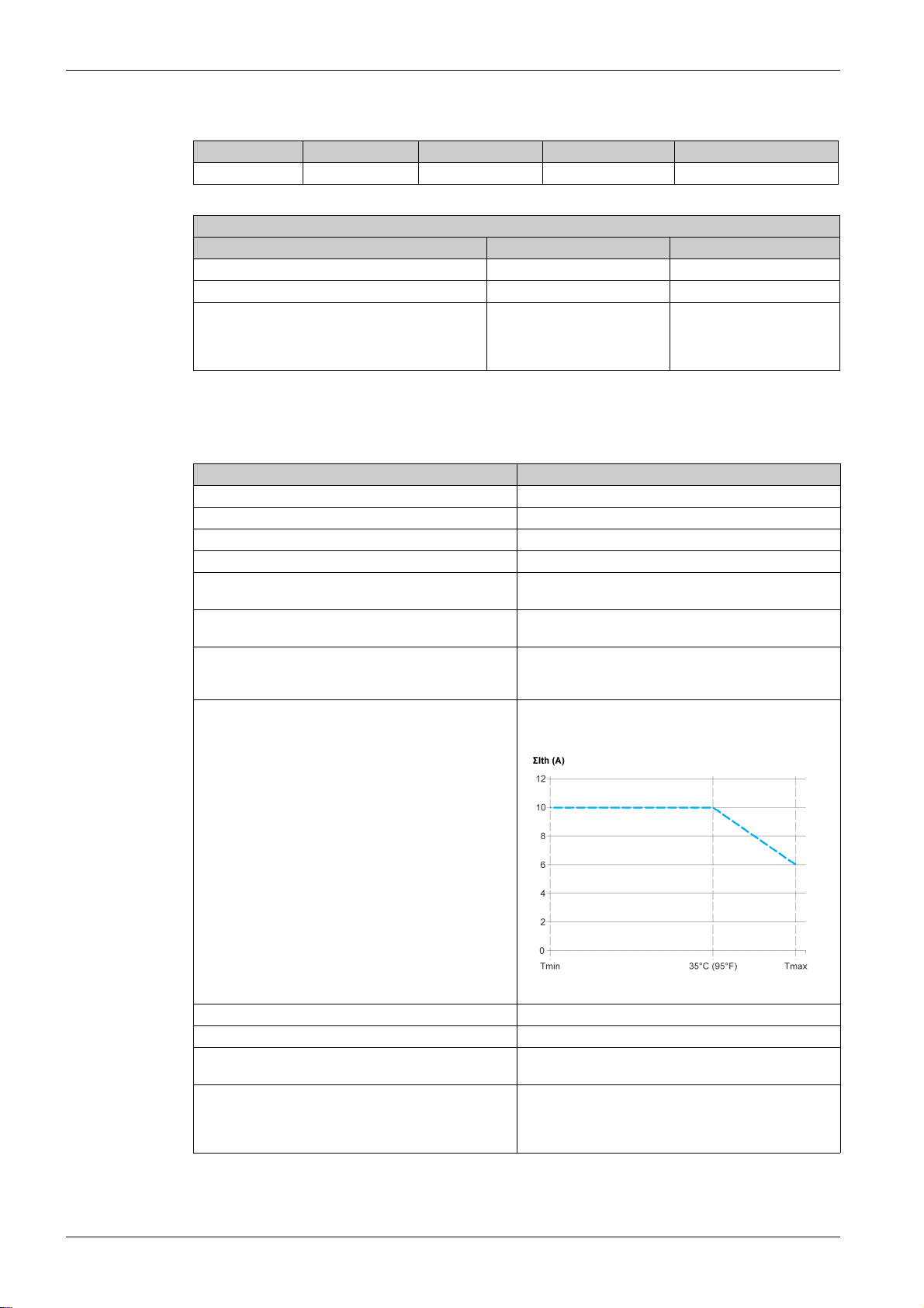
Maximum total thermal current ΣIth in free air up to 55°C
(131 °F) and for side-by-side mounting up to 35°C (95 °F),
per pair of relay contacts
Maximum total thermal current ΣIth for side-by-side
mounting at 55°C (131°F), per pair of relay contacts
(see page 24)
6A
3A
2x10A
2x6A
Derating curve (derating starting at 35 °C (95 °F)):
for test pulse times.
22
Minimum current 10 mA
Minimum voltage 5 V
Utilization category as per UL 60947-5-1 B300 and R300 for Normally Open contacts
Utilization category as per IEC 60947-4-1 and IEC 609475-1)
D300 and R300 for Normally Closed contacts
AC1: 250 V
AC15: 250 V
DC1: 24 V
DC13: 24 V
EIO0000003443 11/2020
Page 23
Characteristic Value
Maximum current, normally open relay contacts AC1: 5 A
Maximum current, normally closed relay contacts AC1: 3 A
External fusing 10 A, category gG, for Normally Open
Additional Non-Safety-Related Outputs
Characteristic Value
Number of semiconductor pulsed outputs 1
Number of semiconductor binary status outputs 1
Output voltage 24 Vdc
Maximum current 20 mA
Technical Data
AC15: 3 A
DC1: 5 A
DC13: 3 A
AC15: 1 A
DC1: 3 A
DC13: 1 A
4 A, category gG, for Normally Closed
EIO0000003443 11/2020 23
Page 24
Technical Data
Timing Data
Maximum Response Times
Characteristic Value
Maximum response time to request at safety-related input 20 ms
Maximum response time after power outage AC 200 ms 100 ms
Maximum response time after power outage DC 140 ms 100 ms
Recovery Time
Characteristic Value
Recovery time after request at safety-related input 200 ms
Switch-On and Activation Delays
Characteristic Value
Switch on delay after power on and automatic start 2500 ms
Delay after activation of safety-related input or valid start
condition
XPSUAT1••••• XPSUAT3•••••
100 ms
Monitored Start
Characteristic Value
Waiting time 2500 ms
Minimum duration of start pulse for monitored start 80 ms
Delay Times for Delay Function of Safety-Related Outputs
Characteristic Value
Possible values 0 s, 0.1 s, 0.2 s, 0.3 s, 0.4 s, 0.5 s, 0.6 s, 0.7 s, 0.8s,
Dynamization of Safety-Related Inputs and Start Input
Characteristic Value
Test pulse duration (safety-related input must be activated
for longer than duration of test pulse)
Test pulse interval 500 ms
Maximum delay of test pulse 40 ms
Test pulse phase shift At least 70 ms
0.9 s, 1 s, 2 s, 3 s, 4 s, 5 s, 6 s, 7 s, 8 s, 9 s, 10 s, 20 s,
30 s, 40 s, 50 s, 60 s, 70 s, 80 s, 90 s, 100 s, 200 s, 300 s,
400 s, 500 s, 600 s, 700 s, 800 s, 900 s
2ms
Debounce Time of Safety-Related Inputs
Characteristic Value
Debounce time, standard 2.5 ms
Debounce time, with OSSD 4 ms
Signal Interlock Monitoring Time
Characteristic Value
Signal interlock monitoring time 200 ms
24
EIO0000003443 11/2020
Page 25

Synchronization Times
The synchronization times for the synchronization of safety-related inputs depend on the application
function
(see page 48)
Technical Data
.
EIO0000003443 11/2020 25
Page 26

Technical Data
Data Functional Safety
Data Functional Safety
Characteristic Value
Defined safe state Safety-related outputs are de-energized
Maximum Performance Level (PL), Category
(as per ISO 13849-1:2015)
Maximum Safety Integrity Level (SIL)
(as per IEC 61508-1:2010)
Safety Integrity Level Claim Limit (SILCL)
(as per IEC 62061:2005+AMD1:2012+AMD2:2015)
Type
(as per IEC 61508-2)
Hardware Fault Tolerance (HFT)
(as per IEC 61508 and IEC 62061)
Stop Category for Emergency Stops
(as per ISO 13850 and IEC 60204-1)
Lifetime in years at an ambient temperature of 55 °C
(131 °F)
Safe Failure Fraction (SFF)
(as per IEC 61508 and IEC 62061)
Probability of Dangerous Failure per hour (PFHD) in 1/h
(as per IEC 61508 and ISO 13849-1)
Mean Time To Dangerous Failure (MTTFd) in years
(high as per ISO 13849-1)
Average Diagnostic Coverage (DC
(high as per ISO 13849-1)
Maximum number of cycles over lifetime DC13, 24 Vdc 1 A: 1200000 with Safe Stop 0
avg
XPSUAT1••••• XPSUAT3•••••
Normally Open: open
Normally Closed: closed
Normally Open: PL e, Category 4
Normally Closed: PL c, Category 1
Actual PL and category depend on wiring and
configuration.
Normally Open: 3
Normally Closed: 1
Actual SIL depends on wiring and configuration.
Normally Open: 3
Normally Closed: 1
Actual SILCL depends on wiring and configuration.
B
1
0 or 1
20
>99 %
0.94 x 10
0.95 x 10
-9
for Safe Stop 0
-9
for Safe Stop 1
1.47 x 10
1.48 x 10
-9
for Safe Stop 0
-9
for Safe Stop 1
>30
)
≥99 %
DC13, 24 Vdc 1 A: 1200000 with Safe Stop 1
DC13, 24 Vdc 3 A: 180000 with Safe Stop 0
DC13, 24 Vdc 3 A: 275000 with Safe Stop 1
AC1, 250 Vac 4 A: 180000 with Safe Stop 0
AC1, 250 Vac 4 A: 90000 with Safe Stop 1
AC15, 250 Vac 1 A: 70000 with Safe Stop 0
AC15, 250 Vac 1 A: 90000 with Safe Stop 1
AC15, 250 Vac 3 A: 39000 with Safe Stop 0
AC15, 250 Vac 3 A: 60000 with Safe Stop 1
26
EIO0000003443 11/2020
Page 27

Electrical durability of the safety-related output relay contacts (instantaneous) as per IEC 60947-5-1
Technical Data
1 Operating cycles
2 Rated current in A
EIO0000003443 11/2020 27
Page 28

Technical Data
Electrical durability of the safety-related output relay contacts (delayed) as per IEC 60947-5-1
1 Operating cycles
2 Rated current in A
Refer to chapter Timing Data
safety calculations.
(seepage24)
for additional technical data that may affect your functional
28
EIO0000003443 11/2020
Page 29

XPSUAT
Engineering
EIO0000003443 11/2020
Engineering
Chapter 3
Engineering
What Is in This Chapter?
This chapter contains the following topics:
Electromagnetic Compatibility (EMC) 30
Basic Principles of Operation 31
Safety-Related Inputs 34
Synchronization of Safety-Related Inputs 36
Dynamization 37
Signal Interlock Monitoring 38
Topic Page
EIO0000003443 11/2020 29
Page 30

Engineering
Electromagnetic Compatibility (EMC)
Conducted and Radiated Electromagnetic Emissions
Equipment of class A as per IEC CISPR 11 is not intended for use in residential environments and may not
provide adequate protection to radio reception in such environments.
INSUFFICIENT ELECTROMAGNETIC COMPATIBILITY
Verify compliance with all EMC regulations and requirements applicable in the country in which the
device is to be operated and with all EMC regulations and requirements applicable at the installation
site.
Do not install and operate devices of class A as per IEC CISPR 11 in residential environments.
Implement all required radio interference suppression measures and verify their effectiveness.
Failure to follow these instructions can result in death, serious injury, or equipment damage.
According to IEC CISPR 11, device type XPSUAT1••••• is a group 1, class B device. Class B as per
IEC CISPR 11 corresponds to environment B as per IEC 60947-1.
According to IEC CISPR 11, device type XPSUAT3••••• is a group 1, class A device. Class A as per
IEC CISPR 11 corresponds to environment A as per IEC 60947-1.
WARNING
30
EIO0000003443 11/2020
Page 31

Basic Principles of Operation
Introduction
The following sections provide basic information on the principles of operation of the device to assist you
in engineering your application function.
Operating States
The following graphic illustrates the operating states and state transitions of the device:
Engineering
State Transitions
Operating state Description In defined
safe state
Off / Configuration Configuration only possible in this operating state Yes
Initialization Self-tests Yes
Run: Outputs Deenergized Regular operation with safety-related function active Yes
Run: Outputs Energized Regular operation with safety-related function not active No
Error Error detected Yes
NOTE: See the chapter Data Functional Safety
State transition Condition
T1
T2
T3
T4
T5
Power on
Initialization successful
Switch on delay has passed
Start condition fulfilled (for example, automatic start or manual start with start
button pressed)
Safety-related inputs activated
For application functions with signal interlock monitoring: no signal interlock
condition
For application functions with synchronization: synchronization time
requirements met
Safety-related inputs deactivated (corresponds to triggering of the safety-
related function)
Error detected on
(see page 26)
for the defined safe state of the device.
EIO0000003443 11/2020 31
Page 32

Engineering
State transition Condition
T6 Power off
NOTE: Refer to the Activation and Deactivation
and “deactivated” in the present document.
Example with Emergency Stop
The following example uses a machine with an Emergency Stop pushbutton, a start pushbutton for manual
start, and a motor to demonstrate the individual operating states and state transitions. The selected
application function is Monitoring of Emergency Stop Circuits. The selected start function is Manual Start.
The example assumes that the equipment is properly wired and configured.
After the device is powered on, it enters the operating state Initialization (T1).
If the initialization is successful, the device enters the operating state Run: Outputs Deenergized (T2).
If an error is detected, the device transitions to the operating state Error (T5).
On entering the operating state Run: Outputs Deenergized, the device verifies the state of the safety-
related inputs and of the start input. The motor is at a standstill.
If the start pushbutton is not pressed, the start input stays deactivated and the device remains in the
operating state Run: Outputs Deenergized. The motor is at a standstill.
Detailed information on the start functions and the timing can be found in the chapter Start Functions
(see page 59)
If the start pushbutton is pressed, the start input is activated, i.e. the start condition is fulfilled.
The state of the safety-related inputs determines whether the device transitions to the operating state
Run: Outputs Energized.
If the safety-related inputs are not activated (actuator of Emergency Stop pushbutton pushed down), the
device remains in the operating state Run: Outputs Deenergized. The motor remains at a standstill.
If the safety-related inputs are activated (actuator of Emergency Stop pushbutton pulled out), the device
transitions to the operating state Run: Outputs Energized (T3). The motor runs. This operating
corresponds to regular operation of the machine.
If an application function with synchronization
transition only occurs if the safety-related inputs are activated within the synchronization time.
In the operating state Run: Outputs Energized, the device monitors the state of the safety-related inputs.
If the actuator of the Emergency Stop pushbutton is pushed down (safety-related inputs deactivated),
the safety-related outputs are deactivated within the response time (transition T4 to operating state Run:
Outputs Deenergized). The device is again in the defined safe state. The motor is stopped.
This corresponds to the Emergency Stop condition of the machine.
To return to the operating state Run: Outputs Energized (T3), the start input and the safety-related
inputs need to be activated again (start button pressed and actuator of the Emergency Stop pushbutton
pulled out).
If an application function with signal interlock monitoring
occurs if there is no signal interlock condition.
If an application function with synchronization
transition only occurs if the safety-related inputs are activated within the synchronization time.
(see page 34)
for details on the use of the terms “activated”
.
(see page 36)
(see page 36)
of the safety-related inputs is used, this
(see page 38)
is used, this transition only
of the safety-related inputs is used, this
Timing Diagram for Example with Emergency Stop
The following timing diagram provides an overview of the example with Emergency Stop.
32
EIO0000003443 11/2020
Page 33

Legend
Item Description
1
2
3
4
5
6
The first safety-related input (A) is activated (actuator of Emergency Stop button pulled out).
The device remains in the defined safe state.
The second safety-related input (B) is activated (second output contact of Emergency Stop
button).
If an application function with synchronization
output (A) is only activated if the second safety-related input (B) is activated within the
synchronization time.
The start button has not yet been pressed so the start condition is not yet fulfilled and the
device remains in the defined safe state.
The start button is pressed.
The start condition is fulfilled. See the chapter Start Functions
information on the start functions.
The safety-related output is activated within the activation delay time
If an application function with synchronization
the safety-related output is only activated if the two channels of the safety-related input have
been activated within the synchronization time.
The motor runs. The device is not in the defined safe state.
The start button is released.
The safety-related input B is deactivated (actuator of Emergency Stop button pushed).
The safety-related output is deactivated within the response time
The Emergency Stop is triggered. The device is in the defined safe state.
The safety-related input A is deactivated (by second output contact of Emergency Stop
button).
If an application function with signal interlock monitoring
related inputs must be deactivated within the signal interlock monitoring time (between (5)
and (6)).
(see page 36)
(see page 36)
(see page 38)
Engineering
is used, the first safety-related
(see page 59)
for detailed
(see page 24)
.
of two input channels is used,
(see page 24)
.
is used, both safety-
EIO0000003443 11/2020 33
Page 34

Engineering
Safety-Related Inputs
Overview
WARNING
INSUFFICIENT AND/OR INEFFECTIVE SAFETY-RELATED FUNCTIONS
Only connect a sensor/device to a safety-related input that meets all requirements as per your risk
assessment and that complies with all regulations, standards, and process definitions applicable to your
machine/process.
Failure to follow these instructions can result in death, serious injury, or equipment damage.
The following sections provide basic information on the safety-related inputs such as principle of activation
and deactivation as well as antivalent behavior. Refer to the chapters Electrical Characteristics
(see page 21)
General Information on Activation and Deactivation of Safety-Related Inputs
In the present document, “activation” of a safety-related input means that a safety-related input changes
its state so that the device can enter the operating state Run: Outputs Energized.
The term “deactivation” of a safety-related input means that a safety-related input changes its state so that
the device enters the operating state Run: Outputs Deenergized.
See Operating States
and Electrical Installation
(see page 31)
(see page 43)
for details on the state machine of the device.
for more details on the safety-related inputs.
Activation and Deactivation with Antivalent Behavior Between Two Safety-Related Inputs with One Input Channel Each
Depending on the selected application function, the safety-related inputs are configured for antivalent
behavior. Antivalent is defined here as a normally open and a normally closed contacts working in
synchronization.
For example, for application function 3
normally open contact, whereas the signal for input channel S22 is provided by a normally closed contact.
Two safety-related inputs with one input channel each with antivalent behavior (magnetic switch with NO
at S12 and NC at S22):
If the level at terminal S12 is logically 0 and the level at terminal S22 is logically 1, the safety-related input
is activated,.
Timing diagram for two safety-related inputs with one input channel each with antivalent behavior:
(see page 51)
, the signal for input channel S12 is provided by a
34
1 = Activation, transition to operating state Run: Outputs Energized
2 = Deactivation, transition to operating state Run: Outputs Deenergized (defined safe state)
EIO0000003443 11/2020
Page 35

Truth table for two safety-related inputs with one input channel each with antivalent behavior:
Engineering
Signal State
at S12
0 1 Safety-related input channel activated, operating state Run: Outputs
1 0 Safety-related input channel deactivated, operating state Run: Outputs
Identical signal states are only permissible within the synchronization time
Signal State
at S22
Activation State and Operating State
Energized
Deenergized
(see page 31)
(see page 36)
. Otherwise,
identical signal states trigger an alert.
The truth table applies to the wiring diagrams presented for the application functions.
If the magnetic switch in the wiring example above is used for guard monitoring, this means that the
magnetic switch is presented in the activated state and the guard is closed.
Consult the manual of the sensor/device you want to use for your application function for details on signal
state required for activation and deactivation as defined in the present document.
EIO0000003443 11/2020 35
Page 36

Engineering
Synchronization of Safety-Related Inputs
Overview
The device can monitor synchronized behavior of the input channels of the safety-related inputs using
various synchronization mechanisms with different synchronization times. If the synchronized input
channels of the safety-related inputs are not activated within the synchronization time, the safety-related
output or outputs are not activated.
The synchronized terminals of the safety-related inputs and the corresponding synchronization times are
also listed for each individual application function
information on the sequences in which the synchronized input channels are activated, if applicable.
Refer to the chapter Safety-Related Inputs
“activation” in the present document.
(see page 48)
(see page 34)
using synchronization, including
for additional information on the use of the term
36
EIO0000003443 11/2020
Page 37

Dynamization
Dynamization of Inputs
Dynamization is used for cross circuit detection between two safety-related inputs or between one safetyrelated input and the Start input or a cross-circuit to an external power supply unit or to ground.
Dynamization is implemented by means of periodically generated test pulses at the control outputs of the
safety-related inputs S•1 and of the start input Y1.
Whether dynamization of the safety-related inputs is used depends on the selected application function
(see page 47)
The following diagram illustrates the dynamization principle and timing:
Engineering
.
The same logic applies to Y1 and Y2.
Designation Value Explanation
T
DDUR
T
DINT
T
DDEL
T
DPSHL
2 ms Duration of the test pulse. The duration of the test pulse is the
time between the start of the test pulse and the end of the test
pulse.
500 ms Interval between test pulses. This interval is the time between the
start of a test pulse and the start of the next test pulse at the same
control output.
40 ms Maximum delay of test pulse. This delay is the maximum time
between the start of the test pulse at the control output and the
associated input channel, that is, the maximum time during which
the input expects to “see” dynamization.
At least 70 ms Phase shift of test pulses. This time is the phase shift between
the test pulses at the control outputs of the safety-related inputs.
EIO0000003443 11/2020 37
Page 38

Engineering
Signal Interlock Monitoring
Overview
Signal interlock is a monitoring function used to detect conditions in which one of the sensors/devices
cannot provide the expected input signal for the device, for example, as a result of contact welding.
The device expects “simultaneous” deactivation of the two safety-related inputs within the signal interlock
monitoring time of 200 ms.
If the two monitored safety-related inputs are not deactivated within 200 ms, this is a signal interlock
condition and the device triggers a signal interlock alert. The device remains in the defined safe state, i.e.,
there is no transition from operating state Run: Outputs Deenergized to operating state Run: Outputs
Energized (T3).
To exit the signal interlock condition, the two affected safety-related inputs must be deactivated for at least
one second. After that, the safety-related inputs can be activated again which activates the safety-related
outputs as well.
Signal interlock is available for certain of the application functions
Examples
The following figure illustrates a condition without signal interlock:
(seepage48)
the device provides.
Both safety-related inputs are deactivated within the signal interlock monitoring time of 200 ms. When they
are activated again, the safety-related outputs are also activated.
The following figure illustrates a condition with signal interlock:
The first safety-related input is deactivated which starts the signal interlock monitoring time of 200 ms. It is
then activated again before the second safety-related input is deactivated. This immediately triggers a
signal interlock alert even though the 200 ms have not yet elapsed.
The following figure illustrates a condition with signal interlock:
38
The first safety-related input is deactivated which starts the signal interlock monitoring time of 200 ms. The
second safety-related remains activated longer than 200 ms. This triggers a signal interlock alert 200 ms
after interlock monitoring has started.
EIO0000003443 11/2020
Page 39

XPSUAT
Installation
EIO0000003443 11/2020
Installat ion
Chapter 4
Installation
What Is in This Chapter?
This chapter contains the following topics:
Prerequisites and Requirements 40
Mechanical Installation 41
Electrical Installation 42
Topic Page
EIO0000003443 11/2020 39
Page 40

Installation
Prerequisites and Requirements
Inspecting the Device
Damaged products may cause electric shock or unintended equipment operation.
ELECTRIC SHOCK OR UNINTENDED EQUIPMENT OPERATION
Do not use damaged products.
Keep foreign objects (such as chips, screws or wire clippings) from getting into the product.
Failure to follow these instructions will result in death or serious injury.
DANGER
Verify the product type by means of the type code
Control Cabinet/Enclosure
Install the device in a control cabinet or enclosure with degree of protection IP54 that is secured by a keyed
or tooled locking mechanism.
The ventilation of the control cabinet/enclosure must be sufficient to comply with the specified ambient
conditions for the device and the other components operated in the control cabinet/enclosure.
Label on Extension Module Connector
The connector for connection of the extension module XPSUEP is covered by a label. Do not remove the
label from the connector unless you want to connect the extension module XPSUEP.
INOPERABLE EQUIPMENT
Do not remove the protective label from the extension connector unless you are immediately attaching
an extension module.
Failure to follow these instructions can result in equipment damage.
(see page 15)
NOTICE
and the data printed on the device.
40
EIO0000003443 11/2020
Page 41

Mechanical Installation
Mounting to DIN Rail
The device can be mounted to the following DIN rails as per IEC 60715:
35 x 15 mm (1.38 x 0.59 in)
35 x 7.5 mm (1.38 x 0.29 in)
Mounting procedure (left illustration)
Step Action
1 Slightly tilt the device and hook it onto the DIN rail.
2 Push the lower part of the device towards the DIN rail.
3 Snap in the DIN rail clip.
Installation
Screw-Mounting
Dismounting procedure (center illustration)
Step Action
1 Unlock the DIN rail clip using a screwdriver.
2 Pull the lower part of the device away from the DIN rail and lift the device towards the top to
remove it from the DIN rail.
Mounting procedure:
Step Action
1 Push the additional fastener into the grooves at the device.
2 Prepare the holes.
3 Screw the device to the mounting surface using the specified screws and a washer M4 as per
ISO 7093 for each screw.
EIO0000003443 11/2020 41
Page 42

Installation
Electrical Installation
General Information
FIRE, ELECTRIC SHOCK OR ARC FLASH
Disconnect all power from all equipment of your machine/process prior to electrical installation of the
Confirm the absence of power using a properly rated voltage sensing device.
Place a "Do Not Turn On" or equivalent hazard label on all power switches and lock them in the non-
Failure to follow these instructions will result in death or serious injury.
Wiring of the device depends on the safety-related function to be implemented. Before wiring the device,
engineer the safety-related function, perform a risk assessment with regard to your machine/process, and
determine the suitability of the device as well as the connected equipment.
Refer to the Schneider Electric Safety Chain Solutions at
examples of wiring the device, including the safety-related outputs with feedback and the start input with
external start condition.
You can wire the device with the terminal blocks in the device or you can remove the terminal blocks. For
the latter, pull the terminal blocks out of the device, connect the individual terminals and push the terminal
blocks back into the device.
Use 75 °C (167 °F) copper conductors to wire the device.
device.
energized position.
DANGER
https://www.se.com
for application-specific
Wire Cross Sections, Stripping Lengths, and Tightening Torques
Characteristic Value
Stripping length for spring terminals 12 mm (0.47 in)
Stripping length for screw terminals 7 ... 8 mm (0.28 ... 0.31 in)
Wire cross section, single wire without wire ferrule
Wire cross section, single wire with wire ferrule
Wire cross section, two wires without wire ferrule
Wire cross section, two wires with uninsulated wire
ferrule
Wire cross section, two wires with insulated wire
ferrule
Tightening torque for screw terminals 0.5 ... 0.6 N m (4.4 ... 5.3 lb in)
(1) Stranded or solid
Block Diagram and Terminals
The following drawings present the block diagram and the terminals with their designations in the
removable terminal blocks.
(1)
0.2 ... 2.5 mm2 (AWG 24 ... 12)
0.25 ... 2.5 mm2 (AWG 24 ... 12)
(1)
0.2 ... 1.5 mm2 (AWG 24 ... 16)
0.25 ... 1 mm
0.5 ... 1.5 mm
2
(AWG 24 ... 18)
2
(AWG 20 ... 16)
42
EIO0000003443 11/2020
Page 43

Terminal Designation Explanation
A1, A2 Power supply
Y1 Control output (DC+) of start input
Y2 Input channel (CH+) of start input
S11, S21 Control outputs (DC+) of positive safety-related
inputs
S31 Control output (DC-) of negative safety-related input
S12, S22 Input channels (CH+) of positive safety-related inputs
S32 Input channel (CH-) of negative safety-related inputs
B2 Terminal for common reference potential for 24 Vdc
signals. The power supplies of the connected
equipment must have a common reference potential
to be connected to this terminal.
13, 14, 23, 24, 33, 34, 47, 48, 57, 58, 67, 68, 75, 76 Terminals of the safety-related outputs
Z1 Pulsed output for diagnostics
safety-related
Z2 Solid state output, not safety-related
EXT Connector for output extension module XPSUEP
(1)
Input can be used to cancel the delay function
(see page 63)
for safety-related outputs.
(see page 73)
, not
Installation
Safety-Related Inputs
WARNING
INSUFFICIENT AND/OR INEFFECTIVE SAFETY-RELATED FUNCTIONS
Only connect a sensor/device to a safety-related input that meets all requirements as per your risk
assessment and that complies with all regulations, standards, and process definitions applicable to your
machine/process.
Failure to follow these instructions can result in death, serious injury, or equipment damage.
The device provides two positive safety-related inputs. Each positive safety-related input consists of one
control output DC+ (terminals S11, S21) and one input channel CH+ (terminals S12, S22).
In addition, the device provides one negative safety-related input. The negative safety-related input
consists of one control output DC- (terminal S31) and one input channel CH- (terminal S32).
The control output of the positive safety-related inputs provides a nominal voltage of 24 Vdc to the
connected sensor/device. The control output of the negative safety-related input provides a nominal
voltage of 0 Vdc to the connected sensor/device. The control output is also used for dynamization
(see page 37)
EIO0000003443 11/2020 43
.
Page 44

Installation
The positive safety-related input switches to 24 Vdc (CH+ has 24 Vdc if activated). The negative safetyrelated input switches to 0 Vdc/reference potential (CH- has 0 Vdc/reference potential if activated).
The negative safety-related input S31-S32 or the positive safety-related input S21-S22 can be used to
cancel the delay function
application function.
If you want to use the delay function for safety-related outputs, also connect the device which is to provide
the cancel signal to the terminals of the appropriate safety-related input S21-S22 or S31-S32. Refer to the
chapter Application Functions
connected for a given application function.
Respect the maximum wire resistance of 500 Ω when determining the cable length. The maximum wire
length between a safety-related input and a sensor/device is 30 m (98.43 ft) if the supply via the control
outputs (terminals S•1) of the safety-related inputs are not used.
Wire the terminals of the safety-related inputs according to the wiring diagram for the application function
(see page 48)
Safety-Related Outputs
The wiring of the safety-related outputs depends on the safety-related function to be implemented.
Install fuses with the rating specified in the chapter Electrical Characteristics
Start Input
(see page 64)
(see page 48)
to be implemented.
for the safety-related outputs, depending on the selected
for information on which safety-related input is to be
(see page 22)
.
WARNING
UNINTENDED EQUIPMENT OPERATION
Do not use the Start function for safety-related purposes.
Use Monitored Start or Startup Test if unintended restart is a hazard according to your risk
assessment.
Failure to follow these instructions can result in death, serious injury, or equipment damage.
The start input consists of one control output DC+ (terminal Y1) and one input channel CH+ (terminal Y2).
The control output provides a nominal voltage of 24 Vdc to the connected sensor/device. It is also used for
dynamization
The wiring of the start input depends on the start function
For automatic start, bridge terminals Y1 and Y2 or connect terminal Y2 to an external 24 Vdc power supply.
For manual start or monitored start and if the control output Y1 (DC+) is to be used:
Connect terminals Y1 and Y2 to the device providing the start signal, such as a push-button.
For manual start or monitored start and if the device providing the start signal is supplied externally:
Connect terminal Y2 to the device providing the start signal, such as a push-button or a logic controller.
Leave terminal Y1 unconnected.
The common reference potential is established via terminal B2.
Respect the maximum wire resistance of 500 Ω when determining the cable length. The maximum wire
length between the start input and a sensor/device is 30 m (98.43 ft) if the supply via the control output
(terminal Y1) of the start input is not used.
(see page 37)
.
(see page 59)
to be implemented.
Additional, Non-Safety-Related Outputs Z1 and Z2
INCORRECT USE OF OUTPUT
Do not use the additional outputs Z1 and Z2 for safety-related purposes.
Failure to follow these instructions can result in death, serious injury, or equipment damage.
Connect the semiconductor pulsed output Z1 to a suitable input of the logic controller if you want to use
the diagnostics pattern the output provides.
44
WARNING
EIO0000003443 11/2020
Page 45

Connect the semiconductor binary status output Z2 to a suitable device for evaluation of the signal
provided via this output. Output Z2 is deactivated as long as the safety-related outputs are activated or if
an error is detected.
The maximum wire length between the additional outputs Z1 or Z2 and connected equipment is 30 m
(98.43 ft)
The common reference potential is established via terminal B2.
Power Supply
Connect the terminals A1 and A2 to a power supply providing the supply voltage specified for the device
in the chapter Electrical Characteristics
Common Reference Potential
Terminal B2 is provided to obtain a common reference potential for 24 Vdc signals.
The power supplies of the connected equipment must have a common reference potential.
(see page 21)
Installation
.
EIO0000003443 11/2020 45
Page 46

Installation
46
EIO0000003443 11/2020
Page 47

XPSUAT
Functions
EIO0000003443 11/2020
Functions
Chapter 5
Functions
What Is in This Chapter?
This chapter contains the following topics:
Application Functions 48
Start Functions 59
Delay Function 63
Topic Page
EIO0000003443 11/2020 47
Page 48

Functions
Application Functions
Introduction
The following sections provide an overview of the available application functions and a detailed listing of
requirements and values of each of the application functions. The chapter Configuration
describes the configuration procedure by means of the selectors of the device.
Overview of Application Functions
(see page 66)
Typical applications Type of outputs of sensor/device providing
the input signal for application function
Monitoring of Emergency Stop circuits
as per ISO 13850 and IEC 60204-1,
stop category 0
Monitoring of Emergency Stop circuits
as per ISO 13850 and IEC 60204-1,
stop category 1
Monitoring of guards as per
ISO 14119/14120 with electrical
switches
Monitoring of guards as per
ISO 14119/14120 with electrical
switches
Monitoring of guards as per
ISO 14119/14120 with coded magnetic
switches
Monitoring of proximity switches
Monitoring of proximity switches One PNP output No No Position 4
Monitoring of pressure-sensitive 4-wire
protective devices such as mats or
edges as per ISO 13856
Monitoring of electro-sensitive
protective equipment such as type 4
light curtains as per IEC 61496-1
Monitoring of RFID sensors
Normally open, normally closed and/or
changeover outputs
One PNP (sensor/device A) and one NPN
(sensor/device B) output
One PNP output Yes No Position 6
One PNP (sensor/device A) and one NPN
(sensor/device B) output
Short-circuit-generating outputs No Yes Position 8
OSSD (Output Signal Switching Device)
outputs
Synchroni
zation
No Yes Position 1
Dynamizat
ion
Application
Function
Selector
(seepage49)
Yes Yes Position 2
(seepage50)
Yes Yes Position 3
(seepage51)
(seepage52)
No No Position 5
(seepage53)
(seepage54)
Yes No Position 7
(seepage55)
(seepage56)
No No Position 9
(seepage57)
Yes No Position 10
(seepage58)
48
EIO0000003443 11/2020
Page 49

Application Function 1
Functions
Characteristic Value/Description
Typical applications Monitoring of Emergency Stop circuits as per
ISO 13850 and IEC 60204-1, stop category 0
Monitoring of Emergency Stop circuits as per
ISO 13850 and IEC 60204-1, stop category 1
Monitoring of guards as per ISO 14119/14120
with electrical switches
Type of outputs of sensor/device providing the input signal
for application function
S•• terminals to be connected S11-S12 and S21-S22
Dynamization Yes
Signal interlock monitoring Between terminals S12 and S22
Synchronization of safety-related inputs No
Normally open, normally closed and/or changeover
outputs
Leave the safety-related input S31-S32 unconnected or
use it to cancel a delay configured with the Delay function
(see page 63)
.
Wiring of the inputs for Emergency Stop
Wiring of the inputs for guards
EIO0000003443 11/2020 49
Page 50

Functions
Application Function 2
Characteristic Value/Description
Typical applications Monitoring of Emergency Stop circuits as per
ISO 13850 and IEC 60204-1, stop category 0
Monitoring of Emergency Stop circuits as per
ISO 13850 and IEC 60204-1, stop category 1
Monitoring of guards as per ISO 14119/14120
with electrical switches
Type of outputs of sensor/device providing the input signal
for application function
S•• terminals to be connected S11-S12 and S21-S22
Dynamization Yes
Signal interlock monitoring Between terminals S12 and S22
Normally open, normally closed and/or changeover
outputs
Leave the safety-related input S31-S32 unconnected or
use it to cancel a delay configured with the Delay function
(see page 63)
.
Synchronization:
Synchronized terminals Synchronization time
S12 synchronized with S22 If S12 is activated before S22, S22 has to be activated
within 2 s.
If S22 is activated before S12, S12 has to be activated
within 4 s.
Wiring of the inputs for Emergency Stop
Wiring of the inputs for guards
50
EIO0000003443 11/2020
Page 51

Application Function 3
Functions
Characteristic Value/Description
Typical applications Monitoring of guards as per ISO 14119/14120
with electrical switches
Monitoring of guards as per ISO 14119/14120
with coded magnetic switches
Monitoring of proximity switches
Type of outputs of sensor/device providing the input signal
for application function
S•• terminals to be connected S11-S12 and S21-S22
Dynamization Yes
Signal interlock monitoring No
Normally open, normally closed and/or changeover
outputs
Leave the safety-related input S31-S32 unconnected or
use it to cancel a delay configured with the Delay function
(see page 63)
.
Synchronization:
Synchronized terminals Synchronization time
S12 synchronized with S22 S12 and S22 have to be activated within 0.5 s.
Wiring of the inputs for coded magnetic switches
EIO0000003443 11/2020 51
Page 52

Functions
Application Function 4
Characteristic Value/Description
Typical applications Monitoring of proximity switches
Type of outputs of sensor/device providing the input signal
for application function
S•• terminals to be connected S12 and S22
Dynamization No
Signal interlock monitoring Between terminals S12 and S22
Synchronization of safety-related inputs No
One PNP output
Leave the safety-related input S31-S32 unconnected or
use it to cancel a delay configured with the Delay function
(see page 63)
.
Wiring of the inputs for sensors/devices with PNP output
52
EIO0000003443 11/2020
Page 53

Application Function 5
Functions
Characteristic Value/Description
Typical applications Monitoring of proximity switches
Type of outputs of sensor/device providing the input signal
for application function
S•• terminals to be connected S12 and S32
Dynamization No
Signal interlock monitoring Between terminals S12 and S32
Synchronization of safety-related inputs No
One PNP (sensor/device A) and one NPN (sensor/device
B) output
Leave the safety-related input S21-S22 unconnected or
use it to cancel a delay configured with the Delay function
(see page 63)
.
Wiring of the inputs for sensors/devices with PNP output and NPN output
EIO0000003443 11/2020 53
Page 54

Functions
Application Function 6
Characteristic Value/Description
Typical applications Monitoring of proximity switches
Type of outputs of sensor/device providing the input signal
for application function
S•• terminals to be connected S12 and S22
Dynamization No
Signal interlock monitoring Between terminals S12 and S22
One PNP output
Leave the safety-related input S31-S32 unconnected or
use it to cancel a delay configured with the Delay function
(see page 63)
.
Synchronization:
Synchronized terminals Synchronization time
S12 synchronized with S22 S12 and S22 have to be activated within 0.5 s.
Wiring of the inputs for sensors/devices with PNP output
54
EIO0000003443 11/2020
Page 55

Application Function 7
Functions
Characteristic Value/Description
Typical applications Monitoring of proximity switches
Type of outputs of sensor/device providing the input signal
for application function
S•• terminals to be connected S12 and S32
Dynamization No
Signal interlock monitoring Between terminals S12 and S32
One PNP (sensor/device A) and one NPN (sensor/device
B) output
Leave the safety-related input S21-S22 unconnected or
use it to cancel a delay configured with the Delay function
(see page 63)
.
Synchronization:
Synchronized terminals Synchronization time
S12 synchronized with S32 S12 and S32 have to be activated within 0.5 s.
Wiring of the inputs for sensors/devices with PNP output and NPN output
EIO0000003443 11/2020 55
Page 56

Functions
Application Function 8
Characteristic Value/Description
Typical applications Monitoring of pressure-sensitive 4-wire
protective devices such as mats or edges as
per ISO 13856
Type of outputs of sensor/device providing the input signal
for application function
S•• terminals to be connected S11-S12 and S31-32
Dynamization Yes
Signal interlock monitoring Between terminals S12 and S32
Synchronization of safety-related inputs No
Short-circuit-generating outputs
Leave the safety-related input S21-S22 unconnected or
use it to cancel a delay configured with the Delay function
(see page 63)
.
Wiring of the inputs for short circuit generating mats or edges
56
EIO0000003443 11/2020
Page 57

Application Function 9
Functions
Characteristic Value/Description
Typical applications Monitoring of electro-sensitive protective
equipment such as type 4 light curtains as per
IEC 61496-1
Monitoring of RFID sensors
Type of outputs of sensor/device providing the input signal
for application function
S•• terminals to be connected S12 and S22
Dynamization No
Signal interlock monitoring Between terminals S12 and S22
Synchronization of safety-related inputs No
OSSD (Output Signal Switching Device) outputs
Leave the safety-related input S31-S32 unconnected or
use it to cancel a delay configured with the Delay function
(see page 63)
.
Wiring of the inputs for sensors/devices with OSSD outputs
EIO0000003443 11/2020 57
Page 58

Functions
Application Function 10
Characteristic Value/Description
Typical applications Monitoring of electro-sensitive protective
equipment such as type 4 light curtains as per
IEC 61496-1
Monitoring of RFID sensors
Type of outputs of sensor/device providing the input signal
for application function
S•• terminals to be connected S12 and S22
Dynamization No
Signal interlock monitoring Between terminals S12 and S22
OSSD (Output Signal Switching Device) outputs
Leave the safety-related input S31-S32 unconnected or
use it to cancel a delay configured with the Delay function
(see page 63)
.
Synchronization:
Synchronized terminals Synchronization time
S12 synchronized with S22 S12 and S22 have to be activated within 0.5 s.
Wiring of the inputs for sensors/devices with OSSD outputs
58
EIO0000003443 11/2020
Page 59

Start Functions
Overview
Functions
WARNING
UNINTENDED EQUIPMENT OPERATION
Do not use the Start function for safety-related purposes.
Use Monitored Start or Startup Test if unintended restart is a hazard according to your risk
assessment.
Failure to follow these instructions can result in death, serious injury, or equipment damage.
The devi ce p rov ide s se ver al s tar t functions which are selected by means of the start function selector. The
start function determines the start behavior of the device after power-on and for a transition from the
operating state Run: Outputs Deenergized (defined safe state) to the operating state Run: Outputs
Energized.
The start behavior is configured using the following characteristics:
Type of start (automatic/manual start and monitored start)
With or without startup test
With or without dynamization
Refer to the chapter Electrical Installation
(see page 37)
(see page 44)
for additional information on wiring the start input.
Automatic Start
With automatic start, the start input is permanently active. This can be achieved by bridging the start input
or providing an external power supply. When the safety-related input is activated, the safety-related
outputs are activated within a maximum of 100 ms (activation delay).
The following timing diagram illustrates the automatic start:
1 Activation delay (100 ms): maximum time between activation of safety-related input and activation of safety-related
output
2 Response time (20 ms): maximum time between deactivation of safety-related input and deactivation of safety-
related output
3 Recovery time (200 ms): time that must pass before the safety-related input can be activated again
The timing diagram exemplifies the timing using one safety-related input and one safety-related output.
The same logic applies in the case of multiple safety-related inputs and/or safety-related outputs.
Manual Start
A manual start requires the start input to be activated. The safety-related outputs are activated after both
the start input and the safety-related inputs have been activated.
EIO0000003443 11/2020 59
Page 60

Functions
The following timing diagram illustrates the manual start:
1 Activation delay (100 ms): maximum time between activation of start input and activation of safety-related output
2 Response time (20 ms): maximum time between deactivation of safety-related input and deactivation of safety-
related output
3 Recovery time (200 ms): time that must pass before the safety-related input can be activated again
The timing diagram exemplifies the timing using one safety-related input and one safety-related output.
The same logic applies in the case of multiple safety-related inputs and/or safety-related outputs.
The signal required for activation of the Start input can be provided, for example, via a push-button, or a
logic controller.
Monitored Start with Falling Edge
In the case of a monitored start with falling edge, the start input must be activated and remain active for a
duration of 80 ms. The safety-related outputs are activated with a falling edge of the start input if the safetyrelated inputs have been activated in the meantime.
1 Activation delay (100 ms): maximum time between deactivation of start input and activation of safety-related output
2 Response time (20 ms): maximum time between deactivation of safety-related input and deactivation of safety-
related output
3 Waiting time after power-on (2500 ms): time that must pass between power-on and activation of the start input
4 Minimum duration of start pulse (80 ms): time for which the start input must be activated before the falling edge at
the start input
The timing diagram exemplifies the timing using one safety-related input and one safety-related output.
The same logic applies in the case of multiple safety-related inputs and/or safety-related outputs.
The signal required for activation of the Start input can be provided, for example, via a push-button or a
logic controller.
Startup Test
60
The startup test is performed after the device is powered on. The startup test is typically used for
applications involving guard monitoring. The start input is permanently activated by, for example, bridging.
After power up, the safety-related inputs must be deactivated and activated before the safety-related
outputs are activated. This is achieved by, for example, opening and closing the guard.
EIO0000003443 11/2020
Page 61

Functions
1 Activation delay (100 ms): time between activation of safety-related input and activation of safety-related output
2 Response time (20 ms): time between deactivation of safety-related input and deactivation of safety-related output
3 Recovery time (200 ms): time that must pass before the safety-related input can be activated again
The timing diagram exemplifies the timing using one safety-related input and one safety-related output.
The same logic applies in the case of multiple safety-related inputs and/or safety-related outputs.
After power up, the safety-related outputs are not activated before each of the safety-related inputs has
been deactivated and activated again, either concurrently or one after the other, regardless of sequence.
If the safety-related inputs are already inactive at startup (power cycle), the startup test is considered to
have been completed and the safety-related outputs are activated once the safety-related inputs have
been activated and the activation delay has passed. If the safety-related inputs are active at power up, they
must be deactivated and activated again for the startup test to complete.
Configuring the Start Function
The start function is configured by means of the start function selector.
Position of start function selector Configured start function
1
2
3
4
5
6
7
8
Manual/automatic start (depends on
sensor/device connected to start input)
Without startup test
With dynamization
Manual/automatic start (depends on
sensor/device connected to start input)
With startup test
With dynamization
Monitored start
Without startup test
With dynamization
Monitored start
With startup test
With dynamization
Manual/automatic start (depends on
sensor/device connected to start input)
Without startup test
Without dynamization
Manual/automatic start (depends on
sensor/device connected to start input)
With startup test
Without dynamization
Monitored start
Without startup test
Without dynamization
Monitored start
With startup test
Without dynamization
EIO0000003443 11/2020 61
Page 62

Functions
A start function with dynamization is typically if the start input is connected to a start push-button. A start
function without dynamization is typically used if the start input is connected to a logic controller. Refer to
the chapter Dynamization
(see page 37)
for details.
62
EIO0000003443 11/2020
Page 63

Delay Function
Overview
Configuration
Functions
The device provides a delay function that allows for delayed deactivation of the delayed safety-related
outputs. The delay is the time between deactivation of the safety-related inputs and the deactivation of the
safety-related outputs. It is also possible to configure a delay for the safety-related outputs of a connected
output extension module XPSUEP.
The delay function is available for the following safety-related outputs: 47-48, 57-58, 67-68 and 75-76.
A configured delay can be canceled by activating the appropriate safety-related inputs S21-22 or S31-32,
depending on the application function
(see page 48)
.
The delay is configured with the delay base selector and the delay factor selector (refer to Front View and
Side View
(seepage13)
for the selectors). The numerical value set by means of the delay base selector
is multiplied by the factor set by means of the delay factor selector. The result is the time delay in seconds
for deactivation of the delayed safety-related outputs.
The position of the delay base selector also determines whether the safety-related outputs of a connected
output extension module XPSUEP are deactivated immediately or with the selected delay time.
Delay factor selector:
Position of delay factor selector Factor
10.0
20.1
30.2
40.3
50.4
60.5
70.6
80.7
90.8
10 0.9
Delay base selector:
Position of delay base selector Base value and behavior of safety-related outputs of
1 1, outputs of extension module instantaneous
2 10, outputs of extension module instantaneous
3 100, outputs of extension module instantaneous
4 1000, outputs of extension module instantaneous
5 1, outputs of extension module delayed
6 10, outputs of extension module delayed
7 100, outputs of extension module delayed
8 1000, outputs of extension module delayed
Configuration Examples
Position of delay
factor selector
3 6 2 seconds Yes
6 1 0.5 seconds No
1 Any 0 seconds No
Position of delay base
selector
output extension module XPSUEP
Delay time Delayed deactivation of outputs of
extension module XPSUEP
EIO0000003443 11/2020 63
Page 64

Functions
Canceling a Configured Delay
The safe state of the device is “safety-related outputs deactivated”, i.e. relays de-energized. Take into
account that the defined safe state of the device is not necessarily identical to the defined safe state of your
machine or process. For example, canceling a configured delay may prematurely trigger the safety-related
function STO or allow untimely access to the zone of operation, depending on your application. A
configured delay is a part of the safety-related function. Cancelation of the delay constitutes a modification
to the safety-related function. You must ensure that any modification of the timing for reaching the defined
safe state of the device via a canceled delay is adapted to the defined safe state of your machine or
process.
INSUFFICIENT AND/OR INEFFECTIVE SAFETY-RELATED FUNCTION
Verify that the cancelation of a configured delay including all ramifications with regard to the timing of
the safety-related function as well as the technical and organizational means of triggering the
cancelation are covered in your risk assessment as per ISO 12100 and/or other equivalent
assessment.
Verify that canceling a configured delay does not compromise or reduce the Safety Integrity Level
(SIL), Performance Level (PL) and/or any other safety-related requirements and capabilities defined
for your machine or process.
Ensure that all necessary organizational measures are taken (such as, but not limited to, operator
training, efficient access control to manually operated equipment, or hazard signs) if a configured
delay can be canceled manually by an operator.
Failure to follow these instructions can result in death, serious injury, or equipment damage.
WARNING
A configured delay can be canceled by activating the inputs S21-22 or S31-32, depending on the
application function
(see page 48)
.
The signal for canceling a configured delay can be provided via an HMI and a logic controller with a
corresponding output, or via a pushbutton.
Use cases for canceling a delay include applications in which the time required for the application to reach
the defined safe state of the machine or process varies greatly. For example, long conveyors may take
considerable time to decelerate to a standstill if they carry heavy loads. If they are empty, such a
deceleration may be achieved in a fraction of the time.
The safe state defined for the conveyor could be, for example, standstill and activation of the safety-related
function Safe Torque Off (STO) to help avoid unintended restart. If you use the safety-related outputs to
control a guard to allow access to the zone of operation of the conveyor once the defined safe state of the
machine or process has been achieved, you would use the maximum time the conveyor takes to reach a
standstill as the delay time. This helps to ensure that access to the zone of operation is not possible as
long as the conveyor is still in motion.
If standstill is reached before the maximum delay time has elapsed (for example, due to a low load), the
machine may be in the defined safe state at an earlier point in time and access to the zone of operation
does not pose a hazard. Under this condition, the delay might be canceled, depending on your risk
assessment.
Another possible scenario would be to trigger the safety-related function STO via the device once the
maximum time required for deceleration to standstill under the maximum possible load condition has
elapsed and the conveyor is at a standstill. If standstill is achieved at an earlier point in time, the configured
delay could be canceled and STO triggered earlier so that the machine or process is available again more
rapidly.
64
EIO0000003443 11/2020
Page 65

XPSUAT
Configuration and Commiss ioning
EIO0000003443 11/2020
Configuration and Commissioni ng
Chapter 6
Configuration and Commissioning
What Is in This Chapter?
This chapter contains the following topics:
Configuration 66
Commissioning 67
Topic Page
EIO0000003443 11/2020 65
Page 66

Configuration and Commissioning
Configuration
Overview
The device detects certain technically incorrect configurations (for example, a configured start function
cannot be used with a configured application function). The device cannot detect unwanted configurations
(for example, automatic start has been configured, but a monitored start is required for your application as
a result of your risk assessment).
INEFFECTIVE SAFETY-RELATED FUNCTION AND/OR UNINTENDED EQUIPMENT OPERATION
Only modify the settings of the selectors of the device if you are fully aware of all effects of such
modifications.
Verify that the settings of the selectors match the intended safety-related function and the
corresponding wiring of the device.
Verify that modifications do not compromise or reduce the Safety Integrity Level (SIL), Performance
Level (PL), and/or any other safety-related requirements and capabilities defined for your
machine/process.
Commission the device before it is used for the first time and after each configuration according to the
instructions in the present manual and in compliance with all regulations, standards, and process
definitions applicable to your machine/process
Failure to follow these instructions can result in death, serious injury, or equipment damage.
WARNING
The device is configured by means of the application function selector, the start function selector, the delay
base selector, and the delay factor selector.
The device must be installed and wired according to the requirements of the safety-related function to be
implemented before you can configure it.
Modifications to the positions of the selectors only become effective after power-up. Remove power from
the device before modifying the position of the selectors. If the positions of the selectors are modified while
power is applied to the device, the device detects a configuration error.
Go through the full commissioning procedure
selectors.
Configuration Procedure
Step Action
(see page 67)
1 Verify that the device has been wired according to the safety-related function to be configured.
2 Remove power if the device is not powered off.
If an extension module XPSUEP is connected, remove power from the extension module as
well.
3 Open the transparent cover of the device.
4 Set the application function selector to the required application function.
5 Set the start function selector to the required start function.
6 Set the delay base selector and the delay factor selector to the required delay function.
7 Commission the device according to the chapter Commissioning
after having modified the positions of the
(see page 67)
.
66
EIO0000003443 11/2020
Page 67

Commissioning
Overview
INEFFECTIVE SAFETY-RELATED FUNCTION AND/OR UNINTENDED EQUIPMENT OPERATION
Commission the device before it is used for the first time and after each configuration.
Commission or recommission the machine/process pursuant to all regulations, standards, and
process definitions applicable to your machine/process.
Only start the machine/process if there are no persons or obstructions in the zone of operation.
Verify correct operation and effectiveness of all functions by performing comprehensive tests for all
operating states, the defined safe state, and all potential error situations.
Document all modifications and the results of the commissioning procedure in compliance with all
regulations, standards, and process definitions applicable to your machine/process.
Failure to follow these instructions can result in death, serious injury, or equipment damage.
Commissioning Procedure
Step Action
Configuration and Commissioning
WARNING
1 Verify correct mechanical and electrical installation
2 Verify correct configuration
3 Verify that there are no persons or obstructions in the zone of operation.
4 Apply power and start the machine/process.
5 Perform comprehensive tests for all operating states, the defined safe state, and all potential
6 Close the transparent cover of the device and seal it with the enclosed sealing strip. Additional
7 Document all modifications and the results of the commissioning procedure.
application.
(see page 66)
If an extension module XPSUEP is connected, apply power to the extension module at the same
time as to the device.
error situations.
sealing strips are available as an accessory. Refer to the chapter Accessories
additional information.
according to the intended application.
(see page 39)
according to the intended
(see page 78)
fo r
EIO0000003443 11/2020 67
Page 68

Configuration and Commissioning
68
EIO0000003443 11/2020
Page 69

XPSUAT
Diagnostics
EIO0000003443 11/2020
Diagnostics
Chapter 7
Diagnostics
INEFFECTIVE SAFETY-RELATED FUNCTION AND/OR UNINTENDED EQUIPMENT OPERATION
Only attempt to resolve alerts and errors detected by the device if you are fully familiar with the safetyrelated applications and the non-safety-related applications as well as the hardware used to operate your
machine/process.
Failure to follow these instructions can result in death, serious injury, or equipment damage.
What Is in This Chapter?
This chapter contains the following topics:
Diagnostics via LEDs 70
Diagnostics via Status Output Z1 73
WARNING
Topic Page
EIO0000003443 11/2020 69
Page 70

Diagnostics
Diagnostics via LEDs
Overview
The device features various LEDs
and detected errors.
Recommission the device
application function selector, the start function selector, or the delay function selectors.
LED POWER
State Meaning
Off No power supply
Solid on Power supply on
LED STATE1
This LED provides information on the state of the instantaneous safety-related outputs.
State Meaning
Off Instantaneous safety-related outputs deactivated
Solid on Instantaneous safety-related outputs activated
(see page 13)
(see page 67)
that provide status information and information on alerts
if, during troubleshooting, you modify the position of the
LED STATE2
LED START
LEDs S••
This LED provides information on the state of the delayed safety-related outputs. Refer to the chapter
Delay Function
State Meaning
Off Delayed safety-related outputs deactivated
Solid on Delayed safety-related outputs activated
(seepage63)
This LED provides information on the start condition. Refer to the chapter Start Function
for details.
(see page 59)
detailed information on the conditions and timing of the selected start function.
State Meaning
Off Start condition not fulfilled
Solid on Start condition fulfilled
Flashing Waiting for start condition to be fulfilled
These LEDs provide information on the state of the corresponding safety-related input terminal.
State Meaning
Off Safety-related input deactivated
Solid on Safety-related input activated
for
LED ERROR - Alerts
70
This LED flashes in conjunction with additional S•• LEDs to indicate alerts. In the case of an alert, the
device transitions to the defined safe state. Remove the cause of the alert to exit the defined safe state and
resume operation. Contact your Schneider Electric service representative if the condition persists.
EIO0000003443 11/2020
Page 71

Diagnostics
State In conjunction with additional
Flashing S•• and S•• Flashing
Flashing S•• and S•• Flashing
LED ERROR - Detected Errors
This LED lights solid in conjunction with additional LEDs to indicate detected errors. In the case of a
detected error, the device transitions to the defined safe state. You must remove the cause of the detected
error and perform a power cycle of the device to exit the defined safe state and resume operation. Contact
your Schneider Electric service representative if the condition persists.
LEDs
Additional LEDs State of
additional LEDs
alternatively
synchronously
Meaning Remedy
Synchronization time
exceeded.
Verify correct operation of the
sensors/devices providing the input
signal.
If synchronization is not required for
your application, use an equivalent
application function without
synchronization.
Signal interlock condition
of two safety-related
inputs.
The two safety-related
inputs affected by the
signal interlock condition
must be deactivated for
Deactivate the two safety-related
inputs affected by the signal
interlock condition for at least
1 second.
Verify correct operation of the
contacts of the sensor/sdevices
providing the input signal.
at least 1 second before
the safety-related
outputs can be activated
again.
State In conjunction with additional
Meaning Remedy
LEDs
Additional LEDs State of
additional LEDs
Solid on STATE1,
STATE2,
Flashing
synchronously
General error detected.
START and S••
Solid on STATE1,
STATE2,
Solid on Configuration error
detected.
START and S••
Solid on POWER Flashing Power supply error
detected.
Solid on STATE1 Flashing Error detected at
instantaneous safetyrelated output.
Solid on STATE2 Flashing Error detected at delayed
safety-related output.
Solid on START Flashing Cross circuit detected at
start input.
Solid on STATE1,
STATE2 and
START
Flashing
synchronously
Error detected at safetyrelated output of
extension module.
Solid on S•• Flashing Cross circuit detected at
safety-related input (for
example, incorrect wiring
or application function
with dynamization
selected, but
dynamization not
supported by connected
sensor/device).
Verify correct wiring.
Verify that the positions of the
selectors are appropriate for the
application to be implemented.
Verify correct wiring.
Use a suitable power supply.
Perform a power cycle.
Perform a power cycle.
Verify correct wiring.
Perform a power cycle.
Verify correct wiring.
Verify correct configuration.
EIO0000003443 11/2020 71
Page 72

Diagnostics
State In conjunction with additional
LEDs
Additional LEDs State of
additional LEDs
Solid on S•• and S•• Flashing
synchronously
Meaning Remedy
Cross circuit detected at
safety-related inputs (for
Verify correct wiring.
Verify correct configuration.
example, incorrect wiring
or application function
with dynamization
selected, but
dynamization not
supported by connected
sensor/device).
72
EIO0000003443 11/2020
Page 73

Diagnostics via Status Output Z1
Overview
INCORRECT USE OF OUTPUT
Do not use the additional outputs Z1 and Z2 for safety-related purposes.
Failure to follow these instructions can result in death, serious injury, or equipment damage.
The pulsed output Z1 provides diagnostics information in the form of a bit pattern. If the output Z1 is
connected to a logic controller, the PreventaSupport library can be used to evaluate the diagnostics
information. The library consists of the function blocks FB_PreventaDiag and FB_PreventaMain. The
function block FB_PreventaDiag converts the bit sequences into diagnostics codes for monitoring the
status of the device. The function block FB_PreventaMain uses the diagnostics codes as input to
perform calculations concerning, for example, maintenance tasks.
Refer to the PreventaSupport Library Guide
Diagnostics Codes
The device encodes diagnostics information into sequences of 10 bits with a total duration of 2 s (each bit
200 ms). The first four bits (0010) represent the beginning of a bit sequence. The next six bits contain the
diagnostics code itself.
The following table lists the bit sequences of the diagnostics codes, the description of the corresponding
status as well as correctives, if applicable.
WARNING
(see page 7)
for details.
Diagnostics
Bit sequence Description Correctives
0010101101 Supply voltage out of
tolerance.
0010000011 General error detected. Verify correct wiring.
0010000110 General error detected
in expansion module.
0010000111 Configuration error
detected. The position
of at least one of the
selectors has been
modified during
operation.
0010001100 Cross circuit detected
at input terminal S12.
0010001111 Cross circuit detected
at input terminal S22.
(1) Type of message: E = Error detected, A = Alert, S = Status information
Verify correct wiring.
Use a suitable power supply.
Perform a power cycle.
If the error persists, replace the device.
Verify correct wiring.
Perform a power cycle of the base safety module and
the connected extension module.
If the error persists, replace the extension module.
Verify that the position of the selectors is appropriate
for the application to be implemented.
Perform a power cycle.
If the error persists, replace the device.
Verify correct wiring.
Verify that the sensor/device providing the input signal
is suitable for cross circuit detection by means of
dynamization. If it is not, use an application function
without dynamization or a sensor/device suitable for
dynamization.
Verify correct operation of sensor/device providing the
input signal.
Perform a power cycle.
Type
E
E
E
E
E
E
(1)
EIO0000003443 11/2020 73
Page 74

Diagnostics
Bit sequence Description Correctives
0010011000 Cross circuit detected
at input terminal S32.
Verify correct wiring.
Verify that the sensor/device providing the input signal
is suitable for cross circuit detection by means of
dynamization. If it is not, use an application function
without dynamization or a sensor/device suitable for
dynamization.
Verify correct operation of sensor/device providing the
input signal.
Perform a power cycle.
0010110000 Cross circuit detected
at start input.
Verify correct wiring.
Verify that the device providing the input signal is
suitable for cross circuit detection by means of
dynamization. If it is not, use a start function without
dynamization or a device suitable for dynamization.
Verify correct operation of device providing the input
signal.
Perform a power cycle.
0010100011 Cross circuit detected
at input used for
Cancel Delay function.
Verify correct wiring.
Verify that the sensor/device providing the input signal
is suitable for cross circuit detection by means of
dynamization. If it is not, use an application function
without dynamization or a sensor/device suitable for
dynamization.
Verify correct operation of sensor/device providing the
input signal.
Perform a power cycle.
0010110011 Synchronization alert.
One of the
synchronized safetyrelated inputs is still
Restore the original condition of the states of the
inputs and retry.
Verify correct operation of sensors/devices providing
the input signals.
deactivated, but the
synchronization time
has already elapsed.
0010100111 Synchronization alert.
Both synchronized
safety-related inputs
have been activated,
Restore the original condition of the states of the
inputs and retry.
Verify correct operation of sensors/devices providing
the input signals.
but not within the
synchronization time.
0010110110 Instantaneous safety-
-S
related outputs are
deactivated, delayed
safety-related outputs
are still activated.
0010110111 Safety-related inputs
-S
deactivated, safetyrelated outputs
deactivated.
0010110101 Input S12 is expected
-S
to change its state. In
the case of a
configuration with
antivalent inputs,
inputs S12 and S13 are
expected to change
their states.
0010111100 Input S22 is expected
-S
to change its state. In
the case of a
configuration with
antivalent inputs,
inputs S22 and S23 are
expected to change
their states.
(1) Type of message: E = Error detected, A = Alert, S = Status information
Type
E
E
E
A
A
(1)
74
EIO0000003443 11/2020
Page 75

Diagnostics
Bit sequence Description Correctives
0010111111 Input S32 is expected
-S
to change its state. In
the case of a
configuration with
antivalent inputs,
inputs S32 and S33 are
expected to change
their states.
0010101011 Waiting for startup test. - S
0010101010 Waiting for rising edge
-S
for automatic/manual
start or monitored start.
0010101110 Start input activated.
-S
Waiting for falling edge
for monitored start.
0010101111 Device in operating
-S
state Run:Outputs
Energized, safetyrelated outputs
activated.
(1) Type of message: E = Error detected, A = Alert, S = Status information
Type
(1)
EIO0000003443 11/2020 75
Page 76

Diagnostics
76
EIO0000003443 11/2020
Page 77

XPSUAT
Accessories, Service, Maint enance, and Disposal
EIO0000003443 11/2020
Accessories, Service, Mainten ance, and Disposal
Chapter 8
Accessories, Service, Maintenance, and Disposal
What Is in This Chapter?
This chapter contains the following topics:
Accessories 78
Maintenance 79
Transportation, Storage, and Disposal 80
Service Addresses 81
Topic Page
EIO0000003443 11/2020 77
Page 78

Accessories, Service, Maintenance, and Disposal
Accessories
Accessories
The following accessories are available for the device:
Description Commercial Reference
Coding bits
The coding bits are used if the terminal blocks are removed to help ensure
correct insertion of the terminal blocks into the device.
30 pieces per packaging unit
Sealing strips
The uniquely numbered sealing strips are used to seal the transparent front
cover of the device to help prevent unauthorized access to the configuration
selectors.
10 pieces per packaging unit
XPSEC
XPSES
78
EIO0000003443 11/2020
Page 79

Maintenance
Service and Repairs
Maintenance Plan
Accessories, Service, Maintenance, and Disposal
The device contains no user-serviceable parts. Do not attempt to open, service, or repair the device.
Maintenance plan:
Ensure that a safety-related function implemented with the device is triggered at the minimum intervals
required by the regulations, standards, and process definitions applicable to your machine/process.
Inspect the wiring at regular intervals.
Tighten the threaded connections at regular intervals.
Verify that the device is not used beyond the specified lifetime
(see page 26)
.
To determine the end of the lifetime, add the specified lifetime to the date of manufacture indicated on
the nameplate
(see page 14)
of the device.
Example: If the date of manufacture indicated on the nameplate is 2019-W10, do not use the device
after week 10, 2039.
As a machine designer or system integrator, you must include this information in the maintenance plan for
your customer.
EIO0000003443 11/2020 79
Page 80

Accessories, Service, Maintenance, and Disposal
Transportation, Storage, and Disposal
Transportation and Storage
Ensure that the environmental conditions
respected.
Disposal
Dispose of the product in accordance with all applicable regulations.
https://www.se.com/green-premium
Visit
per ISO 14025 such as:
EoLi (Product End-of-Life Instructions)
PEP (Product Environmental Profile)
(see page 18)
specified for transportation and storage are
for information and documents on environmental protection as
80
EIO0000003443 11/2020
Page 81

Service Addresses
Schneider Electric Automation GmbH
Schneiderplatz 1
97828 Marktheidenfeld, Germany
Phone: +49 (0) 9391 / 606 - 0
Fax: +49 (0) 9391 / 606 - 4000
Email: info-marktheidenfeld@se.com
Additional Contact Addresses
See the homepage for additional contact addresses:
https://www.se.com
Accessories, Service, Maintenance, and Disposal
EIO0000003443 11/2020 81
Page 82

Accessories, Service, Maintenance, and Disposal
82
EIO0000003443 11/2020
Page 83

XPSUAT
Index
EIO0000003443 11/2020
Index
A
accessories,
activation, safety-related inputs,
alerts,
antivalent behavior, safety-related inputs,
application functions
configuration,
application functions: see index entry functions,
automatic start,
78
34
70
34
66
48
59
B
block diagram,
42
C
Category,
commissioning,
configuration
cross circuit detection,
26
67
application functions,
delay function,
delay function, configuration examples,
start functions,
66
63
61
37
63
D
DCavg,
deactivation, safety-related inputs,
degree of protection,
delay base selector,
delay factor selector,
delay function
diagnostics,
diagram, block,
dimensions,
dynamization,
26
cancelation,
configuration,
overview,
63
70
20
37
34
20
63
63
64
63
42
E
electrical characteristics,
electrical durability, 27,
electro-sensitive protective equipment (type 4 light
curtains) as per IEC 61496-1, monitoring of,
electromagnetic compatibility,
EMC,
30
Emergency Stop circuits as per ISO 13850 and
IEC 60204-1, stop category 0, monitoring of,
Emergency Stop circuits as per ISO 13850 and
IEC 60204-1, stop category 1, monitoring of,
environmental characteristics,
errors, detected,
example Emergency Stop
overview,
timing diagram,
70
32
21
28
57, 58
30
49, 50
49, 50
18
32
F
functional safety data,
functions
automatic start,
configuration of application functions,
configuration of start function,
delay function,
delay function, cancelation,
delay function, configuration,
delay function, configuration examples,
dynamization,
light curtains, type 4 as per IEC 61496-1, monitor-
57, 58
ing of,
manual start,
mats or edges as per ISO 13856, monitoring of,
monitored start with falling edge, 60,
monitoring of electro-sensitive protective equipment (type 4 light curtains) as per IEC 61496-1,
57, 58
monitoring of Emergency Stop circuits as per
ISO 13850 and IEC 60204-1, stop category 0,
50
monitoring of Emergency Stop circuits as per
ISO 13850 and IEC 60204-1, stop category 1,
50
monitoring of guards as per ISO 14119/14120 with
coded magnetic switches,
monitoring of guards as per ISO 14119/14120 with
electrical switches,
monitoring of pressure-sensitive 4-wire protective
devices (mats or edges) as per ISO 13856,
monitoring of proximity switches, 51, 52, 53, 54,
monitoring of RFID sensors, 57,
overview application functions,
signal interlock monitoring,
start functions,
synchronization of safety-related inputs,
26
59
66
61
63
64
63
63
37
59
56
60
49
49
51
49, 50, 51
56
55
58
48
38
59
36
G
guards as per ISO 14119/14120 with coded magnetic
switches, monitoring of,
guards as per ISO 14119/14120 with electrical switches, monitoring of,
51
49, 50, 51
H
HFT,
26
I
input, start
technical data,
wiring,
44
inputs, safety-related
technical data,
wiring,
43
21
21
,
,
EIO0000003443 11/2020 83
Page 84

Index
installation, 40, 41,
control cabinet,
enclosure,
mechanical,
prerequisites,
42
40
40
41
40
L
L,
26
LEDs,
70
lifetime,
light curtains type 4 as per IEC 61496-1, monitoring
of,
26
57, 58
M
maintenance,
manual start,
mechanical characteristics,
monitored start with falling edge,
monitoring of electro-sensitive protective equipment
(type 4 light curtains) as per IEC 61496-1,
monitoring of Emergency Stop circuits as per
ISO 13850 and IEC 60204-1, stop category 0,
monitoring of Emergency Stop circuits as per
ISO 13850 and IEC 60204-1, stop category 1,
monitoring of guards as per ISO 14119/14120 with
coded magnetic switches,
monitoring of guards as per ISO 14119/14120 with
electrical switches,
monitoring of pressure-sensitive 4-wire protective devices (mats or edges) as per ISO 13856,
monitoring of proximity switches, 51, 52, 53, 54,
monitoring of RFID sensors, 57,
mounting,
DIN rail,
screw mounting,
MTTFd,
79
59
20
60
57, 58
49, 50
49, 50
51
49, 50, 51
56
55
58
41
41
41
26
N
nameplate,
14
O
operating cycles over lifetime ,
operating state transitions,
operating states,
operation, environmental characteristics,
output Z1
diagnostics,
technical data,
wiring,
output Z2
technical data,
wiring,
outputs, safety-related
technical data,
wiring,
31
73
23
44
23
44
22
44
26
31
18
power supply
technical data,
wiring,
45
pressure-sensitive 4-wire protective devices (mats or
edges) as per ISO 13856, monitoring of,
proximity switches, monitoring of, 51, 52, 53, 54,
21
56
55
R
response times
technical data,
RFID sensors, monitoring of, 57,
24
58
S
safe state, defined,
Safety Integrity Level,
safety-related inputs
activation,
antivalent behavior,
deactivation,
dynamization,
signal interlock monitoring,
synchronization,
technical data,
wiring,
43
safety-related outputs
technical data,
wiring,
44
service addresses,
SFF,
26
signal interlock monitoring,
signal output Z2
technical data,
wiring,
44
SIL,
26
SILCL,
26
start functions,
automatic start,
configuration,
dynamization,
manual start,
monitored start with falling edge, 60,
start input
technical data,
wiring,
44
diagnostics,
technical data,
wiring,
44
technical data,
wiring,
45
startup test,
state machine,
state transitions,
status output Z1
stop category,
storage, environmental characteristics,
stripping lengths,
supply
synchronization,
26
26
34
34
34
37
38
36
21
22
81
38
23
59
59
61
37
59
60
21
60
31
31
73
23
26
18
20
21
36
P
Performance Level,
PFHD,
26
84
26
EIO0000003443 11/2020
Page 85

T
technical data
degree of protection,
dimensions,
electrical characteristics,
environmental characteristics,
functional safety data,
mechanical characteristics,
operation,
power supply,
response times,
safety-related inputs,
safety-related outputs,
signal output Z2,
start input,
status output Z1,
storage,
stripping lenghts,
supply,
tightening torques terminals,
timing data,
transportation,
weight,
wire cross sections,
tightening torques terminals,
timing data,
transportation, environmental characteristics,
troubleshooting,
type code,
20
18
21
18
21
24
20
24
70
15
20
21
18
26
20
21
24
21
22
23
23
20
20
18
20
20
Index
18
V
view
front view,
side view,
13
13
W
weight,
wire cross sections,
wiring,
20
42
power supply,
safety-related inputs,
safety-related outputs,
start input,
supply,
Z2,
44
45
44
45
Z
Z1 status output
diagnostics,
technical data,
wiring,
Z2 signal output
technical data,
wiring,
ZVEI CB24I,
73
44
44
22
20
43
44
23
23
EIO0000003443 11/2020 85
 Loading...