

Page 1
User Manual Easy-UPS™ On-Line SRV2KL-IN and SRV3KL-IN
Important Safety Information
SAVE THESE INSTRUCTIONS - This manual contains important
instructions that should be followed during installation and maintenance of
the Easy-UPS and batteries.
Read these instructions carefully and look at the equipment to become
familiar with the device before trying to install, operate, service or maintain
it. The following special messages may appear throughout this bulletin or on
the equipment to warn of potential hazards or to call attention to information
that clarifies or simplifies a procedure.
The addition of either symbol to a “Danger” or “Warning”
safety label indicates that an electrical hazard exists which will
result in personal injury if the instructions are not followed.
This is the safety alert symbol. It is used to alert you to potential
personal injury hazards. Obey all safety messages that follow
this symbol to avoid possible injury or death.
DANGER
DANGER indicates a hazardous situation which, if not avoided,
will result in death or serious injury.
WARNING
WARNING indicates a hazardous situation which, if not avoided,
could result in death or serious injury.
CAUTION
CAUTION indicates a hazardous situation which, if not avoided,
could result in minor or moderate injury.
NOTICE
NOTICE is used to address practices not related to physical
injury.
Page 2

Product Handling Guidelines
<18 kg
<40 lb
18-32 kg
40-70 lb
32-55 kg
70-120 lb
>55 kg
>120 lb
Safety and General Information
Inspect the package contents upon receipt. Notify the carrier and dealer if
there is any damage.
• This UPS is for indoor use only.
• Do not operate this UPS in direct sunlight, in contact with fluids, or
where there is excessive dust or high humidity.
• Do not operate the UPS near open windows or doors.
• Be sure the air vents on the UPS are not blocked. Allow adequate space
for proper ventilation.
Note: Allow a minimum of 20 cm clearance on both front and rear sides
of the UPS.
• Environmental factors impact battery life. Elevated ambient
temperatures, poor quality utility power, and frequent discharges will
shorten battery life. Follow the battery manufacturer recommendations.
• Connect the UPS power cable directly to a wall outlet. Do not use surge
protectors or extension cords.
Electrical safety
• When grounding cannot be verified, disconnect the equipment from the
utility power outlet before installing or connecting to other equipment.
Reconnect the power cord only after all connections are made.
• Connection to the branch circuit (mains) must be performed by a
qualified electrician.
• The protective earth conductor for the UPS carries the leakage current
from the load devices (computer equipment). An insulated ground
conductor is to be installed as part of the branch circuit that supplies the
UPS. The conductor must have the same size and insulation material as
the grounded and ungrounded branch circuit supply conductors. The
conductor will be green and with or without a yellow stripe.
• The grounding conductor is to be grounded to earth at the service
equipment, or if supplied by a separately derived system, at the supply
transformer or motor generator set.
Easy-UPS On-Line SRV2KL-IN, SRV3KL-IN2
Page 3

Battery safety
• APC by Schneider Electric uses Sealed Maintenance-Free VRLA
batteries. Under normal use and handling, there is no contact with the
internal components of the batteries. Over charging, over heating or
other misuse of batteries can result in leakage of battery electrolyte.
Released electrolyte is toxic and may be harmful to the skin and eyes.
• Use tool with insulated handles.
• Wear rubber gloves and boots.
• Determine if battery is either intentionally or inadvertently grounded.
Contact with any part of a grounded battery can result in electric shock
or burns by high short-circuit current. The risk of such hazards can be
reduced if grounds are removed during installation and maintenance by
a skilled person
• CAUTION: Before installing or replacing the batteries, remove jewelry
such as wristwatches and rings.
High short circuit current through conductive materials could cause
severe burns.
• CAUTION: Do not dispose of batteries in a fire. The batteries may
explode.
• CAUTION: Do not open or mutilate batteries. Released material is
harmful to the skin and eyes and may be toxic.
.
Radio Frequency Warning
This is a category C2 UPS product. In a residential environment, this product
may cause radio interference, in such a case the user may be required to take
additional measures.
Product Description
The APC by Schneider Electric Easy-UPS is a high performance,
uninterruptible power supply (UPS). The Easy-UPS provides protection to
electronic equipment from utility power blackouts, brownouts, sags, surges,
small utility fluctuations and large disturbances. The Easy-UPS also
provides battery backup power to connected equipment until utility power
returns to normal levels or the batteries are fully discharged.
This user manual is available on the enclosed Documentation CD and on the
APC by Schneider Electric Web site, www.apc.com.
Easy-UPS On-Line SRV2KL-IN, SRV3KL-IN
3
Page 4
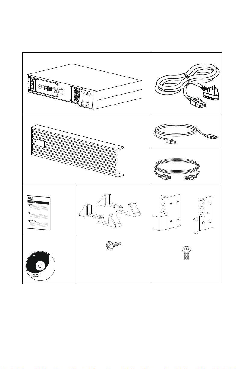
Package Contents
s
u
o
1
3
5
6
a
suo1357a
s
u
o
1
3
6
6
a
s
u
o
1
3
6
7
a
User Documentation
Read the Safety Guide before installing the UPS.
The packaging is recyclable; save it for reuse or dispose of it properly.
Easy-UPS Utility power cable
Front bezel USB cable
Serial communication cable
User Manual Stabiliser brackets x2 pairs
Software, User
Footstand screws x4
documentation CD
NOTE: The model and serial numbers are located on a small, rear panel
label.
Optional Accessories
Refer to the APC by Schneider Electric Web site, www.apc.com, for
available accessories.
Easy-UPS On-Line SRV2KL-IN, SRV3KL-IN4
Rackmount bracket x1 pair
Flat head screws x8
Page 5
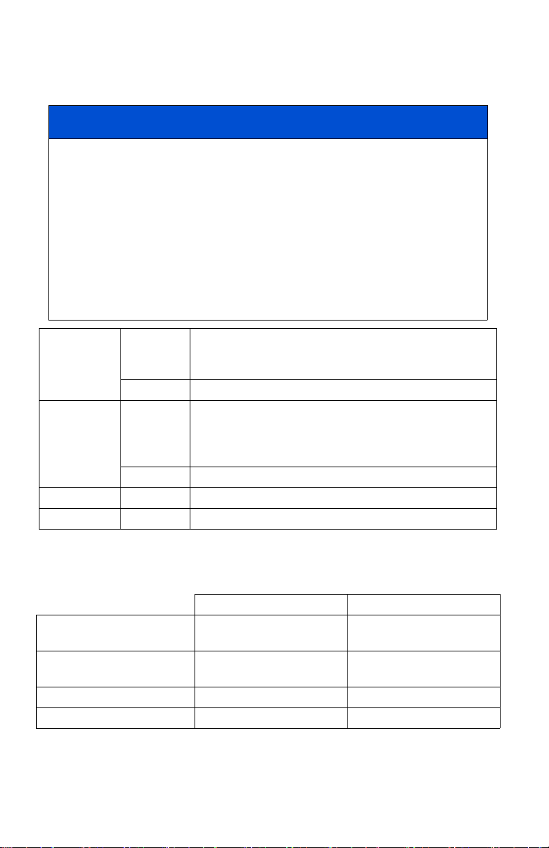
Specifications
Environmental specifications
NOTICE
RISK OF EQUIPMENT DAMAGE
• UPS must be used indoors only.
• The installation location should be sturdy to withstand the weight of
the UPS.
• Do not operate UPS where there is excessive dust or where the
temperature or humidity are outside specified limits.
Failure to follow these instructions can result in equipment
damage.
Operating 0 °C to 40 °C at rated load
Temperature
Storage -20 °C to 60 °C
Operating 0-1,000 m: normal operation
Elevation
Storage 0 - 15,000 m
Humidity 0 to 95% relative humidity, non-condensing
IP Rating IP 20
40 °C to 50 °C linearly derated to 80% of maximum load
capacity
1,000 - 3,000 m: The output power reduces @ 1% at an
increased height of every 100m
>3,000 m: UPS will not work
Note: Charge the battery module atleast every six months during storage.
Physical specifications
SRV2KL-IN SRV3KL-IN
Dimensions with package
Width x Height x Depth
Dimensions without package
Width x Height x Depth
Weight with package 21 kg 32 kg
Weight without package 19 kg 28 kg
Easy-UPS On-Line SRV2KL-IN, SRV3KL-IN
550 mm x 218 mm x 700 mm
(21.7 in x 8.6 in x 27.56 in)
438 mm x 88 mm x 462 mm
(17.2 in x 3.4 in x 18.2 in)
570 mm x 228 mm x 794 mm
(22.4 in x 9 in x 31.3 in)
438 mm x 88 mm x 632 mm
(17.2 in x 3.4 in x 24.9 in)
5
Page 6
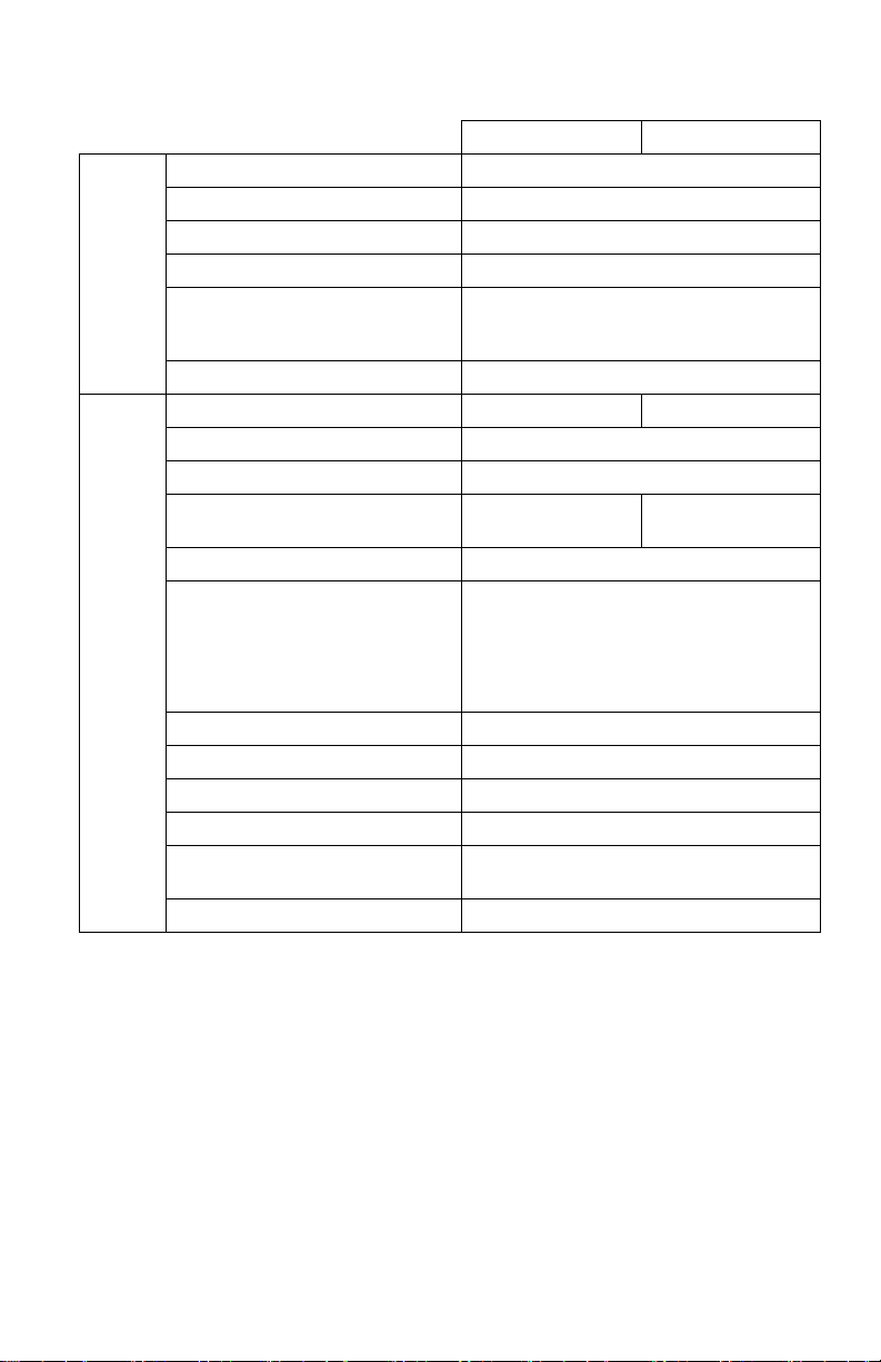
Input/Output specifications
Nominal input voltage 230 V AC nominal
Input frequency 40 - 70 Hz
Input voltage range (100% load) 160 V - 280 V
Input
Output
Input voltage range (50% load) 110 V - 280 V
Input power factor (100% load
resistive load at nominal input
voltage)
Input protection Thermal circuit breaker
UPS Capacity 2000 VA / 1600 W 3000 VA / 2400 W
Nominal output voltage 230 V AC
Other programmable voltage 220 V AC, 240 V AC
Efficiency at rated load at 230V
input
Output voltage regulation ±1% static
Output voltage distortion • 3% max. for full linear load
Frequency - On battery 50 Hz ± 0.5% or 60 Hz ± 0.5%
Frequency - AC mode 50 Hz ± 3 Hz or 60 Hz ± 3 Hz
Crest factor 3:1
Waveform Sinewave
Output connection
Bypass Internal
SRV2KL-IN SRV3KL-IN
≥ 0.95 in online mode
≥ 88% ≥ 90%
• 6% max. for full RCD load
(100% VA, 0.8 PF)
• 15% for the last 60 seconds of the backup
time
Refer to “Rear Panel Features” on page 14
for details.
Easy-UPS On-Line SRV2KL-IN, SRV3KL-IN6
Page 7
Battery
CAUTION
RISK OF HYDROGEN SULPHIDE GAS AND EXCESSIVE
SMOKE
• Replace the battery at least every 5 years.
• Replace the battery immediately when the UPS indicates
battery replacement is necessary.
• Replace battery at the end of its service life.
• Replace batteries with the same number and type of batteries
as originally installed in the equipment.
• Replace the battery immediately when the UPS indicates a
battery over-temperature condition, or UPS internal
over-temperature, or when there is evidence of electrolyte
leakage. Power off the UPS, unplug it from the AC input, and
disconnect the batteries. Do not operate the UPS until the
batteries have been replaced.
Failure to follow these instructions could result in minor or
moderate injury and equipment damage.
Note: The battery in the Easy-UPS is not user-replaceable. Contact APC by
Schneider Electric Support for battery replacement.
SRV2KL-IN SRV3KL-IN
Configuration Internal battery
Typ e Sealed maintenance free (SMF) 12 V, 9 Ah
Battery bank voltage 48 V 72 V
Easy-UPS On-Line SRV2KL-IN, SRV3KL-IN
7
Page 8
Tower Installation
s
u
o
1
3
7
0
a
CAUTION
RISK OF FALLING EQUIPMENT
• The Easy-UPS is heavy.
• Always practice safe lifting techniques adequate for the weight of the
equipment.
• Ensure that the stabilizer brackets are installed when the Easy-UPS
is installed in the tower orientation.
Failure to follow these instructions can result in minor or
moderate injury and equipment damage.
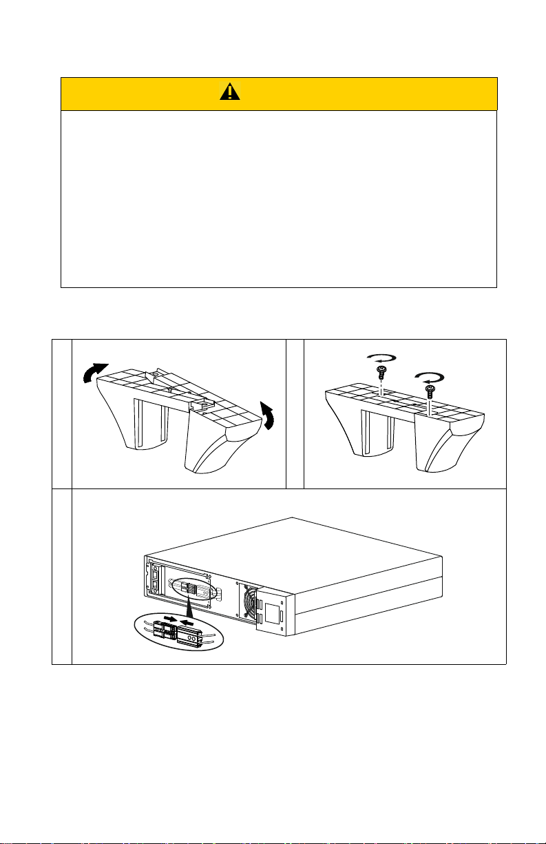
Note: Rotate the front panel display before commencing tower installation.
Refer “Front Panel Display Rotation” on page 10 for details.
Install stabilizer brackets
Snap the battery connectors together
Easy-UPS On-Line SRV2KL-IN, SRV3KL-IN8
Page 9
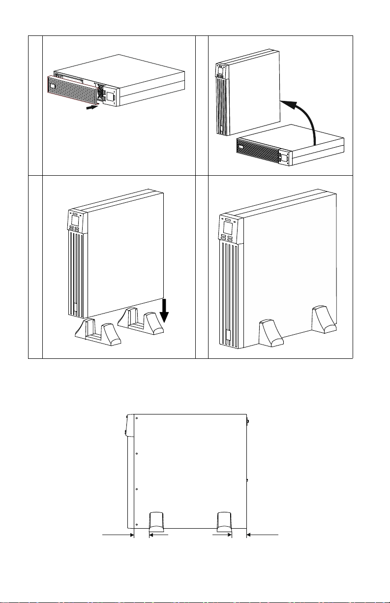
Install the front bezel
s
u
o
1
3
7
1
a
s
u
o
1
3
7
2
a
suo1 373a
suo1374a
70 mm
70 mm
su o1375 a
Note: Maintain approximately 70 mm distance from the edge of the unit,
when installing the stabilizer brackets to the Easy-UPS.
Easy-UPS On-Line SRV2KL-IN, SRV3KL-IN
9
Page 10
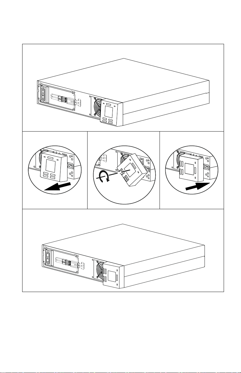
Front Panel Display Rotation
s
u
o
1
3
7
6
a
s
u
o
1
3
8
0
a
Follow below steps to rotate the front panel display module.
Easy-UPS On-Line SRV2KL-IN, SRV3KL-IN10
Page 11

Rack-Mount Installation
s
u
o
1
3
8
1
a
x 8
CAUTION
RISK OF FALLING EQUIPMENT
• The Easy-UPS is heavy.
• Always practice safe lifting techniques adequate for the weight of the
equipment.
• Always use the recommended number of screws to secure brackets
to the UPS.
• Given the heavy weight, the use of rack-mount brackets is
mandatory during rack installation (guide with L-shaped support).
• Always install the UPS at the bottom of the rack.
• Secure the unit in the rack using all the screws supplied for the
purpose.
Failure to follow these instructions can result in minor or
moderate injury
Optional Rail Kit accessory SRVRK1 available for purchase, to enable the
installation of Easy-UPS in rack-mount configuration.
.
Install the rackmount brackets.
Easy-UPS On-Line SRV2KL-IN, SRV3KL-IN
11
Page 12

Lift the Easy-UPS module and slide it into rack enclosure.
suo1382a
suo1 38 3a
s
u
o
1
3
7
0
a
Secure the Easy-UPS module to the rack with screws, nuts and washers (not
supplied)
.
Snap the battery connectors together.
Easy-UPS On-Line SRV2KL-IN, SRV3KL-IN12
Page 13

Install the front bezel.
su o1384 a
Easy-UPS On-Line SRV2KL-IN, SRV3KL-IN
13
Page 14

Rear Panel Features
su o138 5a
su o138 6a
SRV2KL-IN
SRV3KL-IN
Utility power cable connector
Input thermal circuit breaker RESET button
Intelligent card slot for management accessories
USB port
5 A battery backup outlets
Ground screw
16 A battery backup hardwire terminal block
(applicable only for SRV3KL-IN)
Serial communication connector
Easy-UPS On-Line SRV2KL-IN, SRV3KL-IN14
Page 15

Output Hardwiring - SRV3KL-IN
su o143 1a
L
N
CAUTION
RISK OF ELECTRIC SHOCK
• Adhere to all national and local electrical codes.
• All electrical work must be performed by a qualified electrician.
• Turn off all power to this equipment before working on the
equipment.
• Switch the external circuit breaker off. Practice lockout/tagout
procedures.
• Do not wear jewelry when working with electrical equipment.
• Select wire size and connectors according to national and local
codes.
Failure to follow these instructions can result in moderate injury.
• Use 2.5 mm2 gauge wire (not supplied).
1. Locate the cover of the 16 A battery backup hardwire terminal block on
the rear panel of SRV3KL-IN.
2. Remove the screws securing the cover and remove the cover.
3. Connect the line, neutral and ground wires to the terminal block.
Terminals are labeled for proper wire configuration.
4. Replace and secure the cover using the screws removed in step 2.
Easy-UPS On-Line SRV2KL-IN, SRV3KL-IN
15
Page 16

Start Up
Connect equipment and input power to the Easy-UPS
CAUTION
HAZARD OF ELECTRIC SHOCK
• All electrical work must be performed by a qualified electrician.
• Turn off all power to this equipment before working on the
equipment. Practice lockout/tagout procedures.
• Do not wear jewelry when working with electrical equipment.
Failure to follow these instructions can result in moderate injury.
1. Connect equipment either to the 5 A battery backup outlets or to the
16 A battery backup hardwire terminal block in the SRV3KL-IN
Easy-UPS. For connecting equipment to the 16 A battery backup
hardwire terminal block refer “Output Hardwiring - SRV3KL-IN” on
page 15 for details. Avoid using extension cords.
2. Connect input utility power to the Easy-UPS.
3. Switch on the input utility power. The Easy-UPS display panel will
illuminate when utility power is available.
Start the Easy-UPS
Press the
POWER ON/OFF button located on the front panel of Easy-UPS. The
Status LED will illuminate green.
• The battery charges to 90% capacity during the first five hours of normal
operation.
• Do not expect full battery run capability during this initial charge
period.
Cold start the Easy-UPS
Use cold start feature to supply power to connected equipment from the
Easy-UPS batteries.
Press the
Press the
POWER ON/OFF button. The display panel will illuminate.
POWER ON/OFF button again to supply battery power to the
connected equipment.
Easy-UPS On-Line SRV2KL-IN, SRV3KL-IN16
Page 17

Connect and install management software
suo1387a
Easy-UPS is provided with SchneiderUPS management software for
unattended operating system shutdown, monitoring, control and energy
reporting. The following diagram is a representation of a typical server
installation.
Connect the USB cable from the rear of the Easy-UPS to the computer.
Load the SchneiderUPS CD and follow the on-screen set-up instructions.
A built-in serial port is also available for additional communication options with
serial cable.
Additional communication options are available via the built-in intelligent
card slot. Refer to the APC by Schneider Electric Web site, www.apc.com,
for more information.
Easy-UPS On-Line SRV2KL-IN, SRV3KL-IN
17
Page 18

Operation
Mute / Esc
suo1388a
Front display panel features
Easy-UPS models are equipped with an intuitive and configurable LCD
display. The display complements the software interface as they convey
similar information and either may be used to configure the Easy-UPS
settings.
POWER ON/
OFF button
Alert LED The Alert LED illuminates red when the Easy-UPS detects an error and
UP/DOWN
ARROW
button
ENTER
button
MUTE/ESC
button
Press the POWER ON/OFF button to turn the Easy-UPS ON.
Press and hold the POWER ON/OFF button until a beep is heard to turn the
Easy-UPS off.
Press the
blinks red for Easy-UPS notifications. Refer “Alerts and Notifications”
on page 26 for details.
Press the UP/DOWN ARROW button to scroll through the main menu
options and display screens.
Press the ENTER button to enter the menu or to select a menu item/value
during navigation.
POWER ON/OFF button to reset alerts.
Press the MUTE/ESC button:
• To acknowledge audible alerts and suppress them temporarily.
• To exit a sub menu and return to the main menu.
Easy-UPS On-Line SRV2KL-IN, SRV3KL-IN18
Page 19

ALARM
X
LCD
Display
Status
LED
The display interface options are visible on this LCD screen. Press any
button to activate LCD, if the display is not illuminated.
The Status LED illuminates green when the power is on. The LED
indicates two different states of output power:
• Output off: LED blinks on and off. Press
the output power on.
• Output on: LED illuminates green continuously.
Front display icons
On Line: The Easy-UPS is drawing utility power and performing
double conversion to supply power to the connected equipment.
On Battery: The Easy-UPS is supplying battery backup power to the
connected equipment.
ON BATT
Replace Battery: The battery is not connected securely or the battery
is nearing the end of its service life and should be replaced.
Bypass: The Easy-UPS is in bypass mode, sending utility power
directly to connected equipment. Bypass mode operation is the result
of an internal UPS event, an overload condition, or a user initiated
command either through an accessory. Battery operation is not
available while the Easy-UPS is in bypass mode. Refer “Alerts and
Notifications” on page 26 for details. This icon in combination with
Green Mode icon, indicates that the Easy-UPS is in green mode
operation.
System Alerts: An internal fault is detected. Refer “Alerts and
Notifications” on page 26 for details.
POWER ON/OFF button to turn
Overload: The equipment connected to the Easy-UPS is drawing
more power than rated.
Battery Charge: The battery charge level is indicated by the number
of bar sections illuminated. When all five blocks are illuminated, the
battery is fully charged. Each bar represents approximately 20% of
the battery charge capacity.
Load Level: The load percentage is indicated by the number of load
bar sections illuminated. Each bar represents approximately 20% of
the load.
Mute: An illuminated line through the icon indicates that the audible
alert is disabled.
Easy-UPS On-Line SRV2KL-IN, SRV3KL-IN
19
Page 20

Green Mode: An illuminated icon indicates that the unit is working
G
in Green mode. The connected equipment is receiving the utility
input directly as long as the input voltage and frequency are within
the configured limits.
Alert or notification: The Easy-UPS has detected an error or the
Easy-UPS is in configuration mode. Refer “Alerts and Notifications”
on page 26 for details.
EVENT
Event: The icon is illuminated when the user is viewing the event
log.
LO
Status Indicators
Audible Alert Condition
Continuous beeps, every half
second
4 beeps every 30 sec
(first beep starts after 4 sec on
battery)
Beeper continuously on Alert State - Easy-UPS has detected an error. Refer
Short beep every 2.5 sec Battery disconnected.
Continuous short beeps for
every half second for 1 minute,
repeats every 5 hours
Two short beeps every 5 sec Event Bypass State - Easy-UPS has detected an error.
Low Battery State - The battery is nearing its discharge
state. The Easy-UPS is about to shutdown.
Overload condition - The equipment connected to the
Easy-UPS is drawing more power than rated.
On Battery State - The Easy-UPS is supplying battery
backup power to the connected equipment.
“Alerts and Notifications” on page 26 for details.
Bad battery (replace).
Connected equipment receives utility input power
through the bypass relay.
Easy-UPS Display Parameters
Operational data displayed in the display panel is given in the table.
Navigate using the
Parameter Units Indicator Icons
Output voltage V AC OUT, V
Output frequency Hz OUT, Hz
Input voltage V AC IN, V
Input frequency Hz IN, Hz
UP/DOWN ARROW buttons.
Easy-UPS On-Line SRV2KL-IN, SRV3KL-IN20
Page 21

Parameter Units Indicator Icons
State of battery charge %BAT, %
Battery voltage V DC BAT, V
Ambient temperature ° C NUMBER, C
Remaining On Battery runtime Minutes BAT, Min
Load level in percentage
(Maximum of Watts or VA)
Load level in kVA kVA OUT, kVA
Total Ah capacity of connected battery Ah BAT, Ah
% OUT, %
Configuration
Easy-UPS settings
Configure Easy-UPS settings using the display interface. Refer “Configure
Easy-UPS parameters” on page 23 to edit the parameters.
Function
Output voltage 230 V AC 220, 230,
Audible alert Enable
Green mode/
high efficiency
mode
Factory
Default
Disabled
User Selectable
Options Description
240 V AC
• Enable
•Disable
• Enable
•Disable
Allows the user to select output voltage
while the Easy-UPS is operating online.
Easy-UPS will mute audible alerts when
set to disable or when the display panel
buttons are pressed.
When this mode is enabled, connected
equipment receives utility input power
through the bypass relay as long as input
voltage is within the range of ±5% of
configured output voltage and ±3 Hz of
configured output frequency. Inverter is
turned off during this mode.
If utility power input goes out of range,
inverter is turned on and the load is
transferred to online mode or battery
mode.
The power to the connected equipment
may be interrupted up to
10 milliseconds.
Easy-UPS On-Line SRV2KL-IN, SRV3KL-IN
21
Page 22

Function
Factory
Default
User Selectable
Options Description
Minimum
battery capacity
to restart setting
0% 0%, 15%, 50%,
90%
Easy-UPS output will not be turned on
until the battery is charged to a level
such that it can provide the runtime
configured by this setting. If configured
to 0%, Easy-UPS output is turned on
immediately after utility power returns.
Low battery
state indication
setting
2 min 2 min, 5 min,
7 min, 10 min
The Easy-UPS will emit an audible
alarm when the actual run time reaches
the limit set by the user. The audible
alarm will emit only when the EasyUPS is working in battery mode.
Advanced display navigation
The Easy-UPS display has three menu options. Press the ENTER button from
the Home Screen to access these menu options. Use the
buttons to navigate between the menu options.
Menu option Description
Show Event Log
Use this menu option to see the Easy-UPS event log. The Easy-UPS records
the last 10 events and displays the codes in this log.
Press the
the logged events. The
the DOWN ARROW button navigates to new events.
Every log entry has a numeric and textual event code.
At the end of the log, the word “End” will be displayed.
Press the
ENTER button to see the log. Use the UP/DOWN ARROW buttons to see
UP ARROW button navigates towards old events and
MUTE/ESC button to return to the Home Screen.
UP/DOWN ARROW
Configure the Easy-UPS
Use this menu option to configure the Easy-UPS parameters.
Press the
ENTER button to see the configuration options.
Refer “Configure Easy-UPS parameters” on page 23 for details.
Press the MUTE/ESC button to return to the Home Screen.
Show Easy-UPS information
Use this menu option to see the Easy-UPS information.
Press the
Press the
Press the
ENTER button to see the rating of the Easy-UPS.
UP ARROW button to see the Easy-UPS firmware version.
MUTE/ESC button to return to the Home Screen.
Easy-UPS On-Line SRV2KL-IN, SRV3KL-IN22
Page 23

Menu option Description
User Command to bypass
Use this menu option to switch the Easy-UPS to bypass mode or bring the
Easy-UPS to online mode from bypass mode.
ENTER button:
Press
Put: Use to switch the Easy-UPS to bypass mode of operation.
Note: Power to the connected equipment will drop, if the mains
voltage is not within the threshold limits.
Out: Bring the Easy-UPS out of bypass and restore clean power
to the connected equipment.
Execute Battery Self Test
Use this menu option to conduct a self test and determine the battery status.
Press the
ENTER button to initiate the test.
If the test command is accepted, the Easy-UPS will initiate a self test and will
start a count down on the display.
Display messages are shown at the end of the test.
Test refused. The output is off or battery is not charged.
Test not passed.
Test passed.
Test is aborted due to internal reasons.
Press the
MUTE/ESC button to return to the Home Screen.
Configure Easy-UPS parameters
Follow the steps to configure parameters in the Easy-UPS:
1. Press the
2. Press the
3. Press the
ENTER button.
UP/DOWN ARROW buttons to navigate to “Set”.
ENTER button.
4. Navigate through the parameters using the
5. Press the
ENTER button to edit a parameter. Icons start flashing to indicate
the editing.
6. Press the
UP/DOWN ARROW buttons to navigate between the options
available for the selected parameter.
Easy-UPS On-Line SRV2KL-IN, SRV3KL-IN
UP/DOWN ARROW buttons.
23
Page 24

7. Press the ENTER button to select the option or MUTE/ESC button to abort
the editing of current parameter. Flashing of icons stops after this.
8. Press the
9. Press the
UP/DOWN ARROW buttons to navigate between parameters.
MUTE/ESC button to exit menu navigation.
Troubleshooting
Use the table below to solve minor installation and operation problems.
Refer to the APC by Schneider Electric
assistance with complex Easy-UPS problems.
Problem and/or Possible Cause Solution
Easy-UPS will not turn ON when utility input is available or there is no power output
The Easy-UPS is not turned on. Press the POWER button to turn on the Easy-UPS.
Web site
, www.apc.com for
The Easy-UPS is not connected
to utility power supply.
Input thermal circuit breaker on
the Easy-UPS is tripped.
Easy-UPS, when connected to battery, is not supplying power to the connected
equipment
The Easy-UPS is not turned on. If the Easy-UPS has shutdown (the display is not on),
The battery is not connected. Connect battery to the Easy-UPS. Refer “Snap the battery
Low battery cut off. Easy-UPS
may have discharged the battery
due to utility power outage and
turned the output off due to low
battery condition.
Easy-UPS emits an audible beeping sound at long intervals
The Easy-UPS is operating
normally when running on
battery.
Check that the power cable from the Easy-UPS to the
utility power supply is securely connected at both ends.
Press the input thermal circuit breaker
rear panel.
follow the “Cold start the Easy-UPS” on page 16
procedure.
connectors together.” on page 12 for details.
Wait for the utility power to return and charge the battery.
To turn on the output power after utility power returns,
press
POWER ON button.
The Easy-UPS is operating on battery. See the status of
the Easy-UPS in the display panel.
RESET button in the
Easy-UPS On-Line SRV2KL-IN, SRV3KL-IN24
Page 25

Problem and/or Possible Cause Solution
Alert LED is illuminated. The Easy-UPS displays an alert message and emits a
constant beeping sound
The Easy-UPS has detected an
Refer “Alerts and Notifications” on page 26 for details.
error.
No audible sounds from Easy-UPS even when the Alert LED is illuminated
Audible alert is disabled. Change the Easy-UPS configuration to enable audible
alerts.
Easy-UPS is not providing expected backup time
The Easy-UPS battery is
discharged due to a recent power
outage.
The batteries require recharging after extended outages.
Batteries can wear faster when put into service without
proper recharging or when operated at elevated
temperatures.
The battery is near the end of its
service life.
If the battery is near the end of its service life, consider
replacing the battery, even if the replace battery indicator
is not illuminated.
Easy-UPS is not turning off
POWER OFF button not pressed
properly.
Press and hold the POWER OFF button until the beep is
heard to power off the Easy-UPS.
Utility input power is available. Easy-UPS logic power can not be turned off if utility
input power is available. To turn off the Easy-UPS, turn
off utility input power and press
POWER OFF button.
Release when a beep is heard.
Easy-UPS is in Bypass mode and the LED is not illuminated red
Easy-UPS is in green mode. Disable green mode if not desired.
Easy-UPS is configured to stay
Change the configuration to exit bypass mode.
in the bypass mode.
Easy-UPS is in bypass mode
even after over temperature
Wait for some time for the Easy-UPS to come back to
online mode.
alarm is cleared.
Easy-UPS On-Line SRV2KL-IN, SRV3KL-IN
25
Page 26

Problem and/or Possible Cause Solution
The Easy-UPS has experienced
an overload condition and
transferred to bypass.
Easy-UPS detected an error and
transferred to bypass.
Connected equipment exceeds the maximum load as
defined in specifications.
The alerts remain on until the overload condition is
corrected. Disconnect nonessential equipment from the
Easy-UPS to eliminate the overload condition.
The Easy-UPS continues to supply power as long as it is
in bypass mode and the circuit breaker does not trip. The
Easy-UPS will not provide battery power in the event of a
utility voltage interruption.
Refer “Alerts and Notifications” on page 26 for details.
Alerts and Notifications
Easy-UPS displays a text code and a numeric code on the display when it
detects an error.
Alerts
Display
code
Description Solution
Easy-UPS has
experienced a short
circuit at the output.
Check if there is any short circuit at the Easy-UPS
output. Remove the short circuit and press
POWER ON/OFF button to start the Easy-UPS.
Easy-UPS is
experiencing an
overload condition.
The Easy-UPS has
detected a DC
voltage error. Unit
will try to
auto-recover from
this condition.
Temperature of the
unit is rising above
the set limits.
Easy-UPS On-Line SRV2KL-IN, SRV3KL-IN26
Disconnect nonessential equipment from the
Easy-UPS to eliminate the overload condition.
Wait for the Easy-UPS to auto-recover.
If the Easy-UPS does not recover automatically,
contact APC by Schneider Electric.
Disconnect non-essential equipment from the
Easy-UPS to reduce the Easy-UPS load.
Ensure that ambient temperature is within limits.
Ensure that adequate clearance is maintained.
Page 27

Display
code
Description Solution
Easy-UPS has
detected a charger
error.
Contact APC by Schneider Electric for all other alert codes.
Verify if there is any short circuit at the Easy-UPS
battery terminal.
Press POWER ON/OFF button to start the Easy-UPS.
Notifications
Display code Description Solution
Battery is not
connected.
Connect battery to the Easy-UPS. Refer “Snap the
battery connectors together.” on page 12 for details.
Service
If the unit requires service, do not return it to the dealer. Follow these steps:
1. Review the Troubleshooting section of the manual to eliminate common
problems.
2. If the problem persists, contact APC by Schneider Electric Customer
Support.
a. Note the model number and serial number and the date of purchase.
The model and serial numbers are located on the rear panel of the unit
and are available through the LCD display on select models.
b. Call APC by Schneider Electric Customer Support and a technician
will attempt to solve the problem over the phone. If this is not
possible, the technician will issue a Service Request Number.
c. If the unit is under warranty, the repairs are free.
An Authorised Service Representative will visit your location and try to
resolve the issue.
Limited Factory Warranty
Schneider Electric IT Business India Private Ltd. (SEITBIPL), warrants its products to be
free from defects in materials and workmanship for a period of two (2) years from the date
of purchase. The SEITBIPL obligation under this warranty is limited to repairing or
replacing, at its own sole option, any such defective products or parts there of. Repair or
replacement of a defective product or part thereof does not extend the original warranty
period.
Easy-UPS On-Line SRV2KL-IN, SRV3KL-IN
27
Page 28

This warranty applies only to the original purchaser who must have properly registered the
product within 10 days of purchase. Products may be registered online at
warranty.apc.com or by mailing in the completed warranty registration card that is
included with the documentation.
SEITBIPL shall not be liable under the warranty if its testing and examination disclose
that the alleged defect in the product does not exist or was caused by end user or any third
person misuse, negligence, improper installation, testing, operation or use of the product
contrary to SEITBIPL recommendations or specifications. Further, SEITBIPL shall not be
liable for defects resulting from: 1) unauthorized attempts to repair or modify the product,
2) incorrect or inadequate electrical voltage or connection, 3) inappropriate on site
operation conditions, 4) Acts of God, 5) exposure to the elements, 6) theft. In no event
shall SEITBIPL have any liability under this warranty for any product where the serial
number has been altered, defaced, or removed, 7) normal wear resulting from frequent
use.
EXCEPT AS SET FORTH ABOVE, THERE ARE NO WARRANTIES, EXPRESS
OR IMPLIED, BY OPERATION OF LAW OR OTHERWISE, APPLICABLE TO
PRODUCTS SOLD, SERVICED OR FURNISHED UNDER THIS AGREEMENT
OR IN CONNECTION HEREWITH.
SEITBIPL DISCLAIMS ALL IMPLIED WARRANTIES OF
MERCHANTABILITY, SATISFACTION AND FITNESS FOR A PARTICULAR
PURPOSE.
SEITBIPL EXPRESS WARRANTIES WILL NOT BE ENLARGED,
DIMINISHED, OR AFFECTED BY AND NO OBLIGATION OR LIABILITY
WILL ARISE OUT OF, SEITBIPL RENDERING OF TECHNICAL OR OTHER
ADVICE OR SERVICE IN CONNECTION WITH THE PRODUCTS.
THE FOREGOING WARRANTIES AND REMEDIES ARE EXCLUSIVE AND IN
LIEU OF ALL OTHER WARRANTIES AND REMEDIES. THE WARRANTIES
SET FORTH ABOVE CONSTITUTE SEITBIPL’S SOLE LIABILITY AND
PURCHASER’S EXCLUSIVE REMEDY FOR ANY BREACH OF SUCH
WARRANTIES. SEITBIPL WARRANTIES EXTEND ONLY TO ORIGINAL
PURCHASER AND ARE NOT EXTENDED TO ANY THIRD PARTIES.
IN NO EVENT SHALL SEITBIPL, ITS OFFICERS, DIRECTORS, AFFILIATES
OR EMPLOYEES BE LIABLE FOR ANY FORM OF INDIRECT, SPECIAL,
CONSEQUENTIAL OR PUNITIVE DAMAGES, ARISING OUT OF THE USE,
SERVICE OR INSTALLATION OF THE PRODUCTS, WHETHER SUCH
DAMAGES ARISE IN CONTRACT OR TORT, IRRESPECTIVE OF FAULT,
NEGLIGENCE OR STRICT LIABILITY OR WHETHER SEITBIPL HAS BEEN
ADVISED IN ADVANCE OF THE POSSIBILITY OF SUCH DAMAGES.
SPECIFICALLY, SEITBIPL IS NOT LIABLE FOR ANY COSTS, SUCH AS LOST
PROFITS OR REVENUE, WHETHER DIRECT OR INDIRECT, LOSS OF
EQUIPMENT, LOSS OF USE OF EQUIPMENT, LOSS OF SOFTWARE, LOSS OF
DATA, COSTS OF SUBSTITUANTS, CLAIMS BY THIRD PARTIES, OR
OTHERWISE.
Easy-UPS On-Line SRV2KL-IN, SRV3KL-IN28
Page 29

To obtain service under warranty you must call customer support. Customers with
warranty claims issues may access the SEITBIPL worldwide customer support network
through the SEITBIPL Web site: www.apc.com. Select your country from the country
selection drop down menu. Open the Support tab at the top of the web page to obtain
information for customer support in your region. Refer to the product user manual for
more information on how to contact customer support.
Easy-UPS On-Line SRV2KL-IN, SRV3KL-IN
29
Page 30

Easy-UPS On-Line SRV2KL-IN, SRV3KL-IN30
Page 31

Easy-UPS On-Line SRV2KL-IN, SRV3KL-IN31
Page 32

APC by Schneider Electric Customer Support
Internet http://www.apc.com/support
To ll F re e 18001030011/18004194272
E-mail indiainfo@apc.com
© 2018 APC by Schneider Electric. APC, the APC logo, and Easy-UPS are
owned by Schneider Electric Industries S.A.S., or their affiliated companies. All
other trademarks are property of their respective owners.
EN 990-91218
11/2018
 Loading...