

Page 1
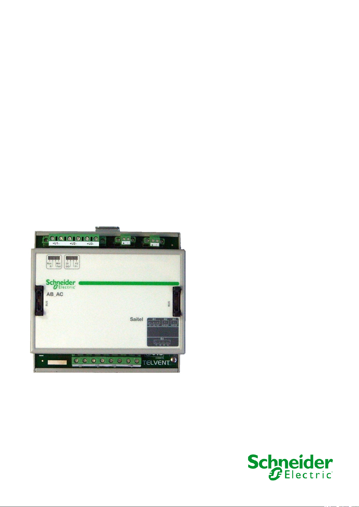
Saitel DP
M562x0000y / AB_AC
User Manual
This manual provides information for the assembly, wiring, configuration and
maintenance of the AB_AC module.
SE-M562-USR
Publication Date (05/2020)
Read carefully the information contained in this manual before assembly, installation and use of the
equipment.
www.schneider-electric.com
Page 2
07/05/2020
User Manual – AB_AC
Page 2
R&D Digital Seville
HUe
11.06.06
HU_A
11.06.17
Linux
HUe
18.07.17.10.42.53
VxWork
HU_A
VxW_19_06_27_15_35_02
Easergy Builder Tool
Core
1.5.9.1
DSP
1.0.4
AT90CAN
02.00.13
Change control
01 04/09/2019 Initial edition.
Rev Date Description
02 07/05/2020
General Information
The Saitel platform and all its components have been developed in accordance to the requirements
for a quality management system, complying with the ISO 9001:2015 Norm.
Document nº:
Revision/Date:
File:
Retention period:
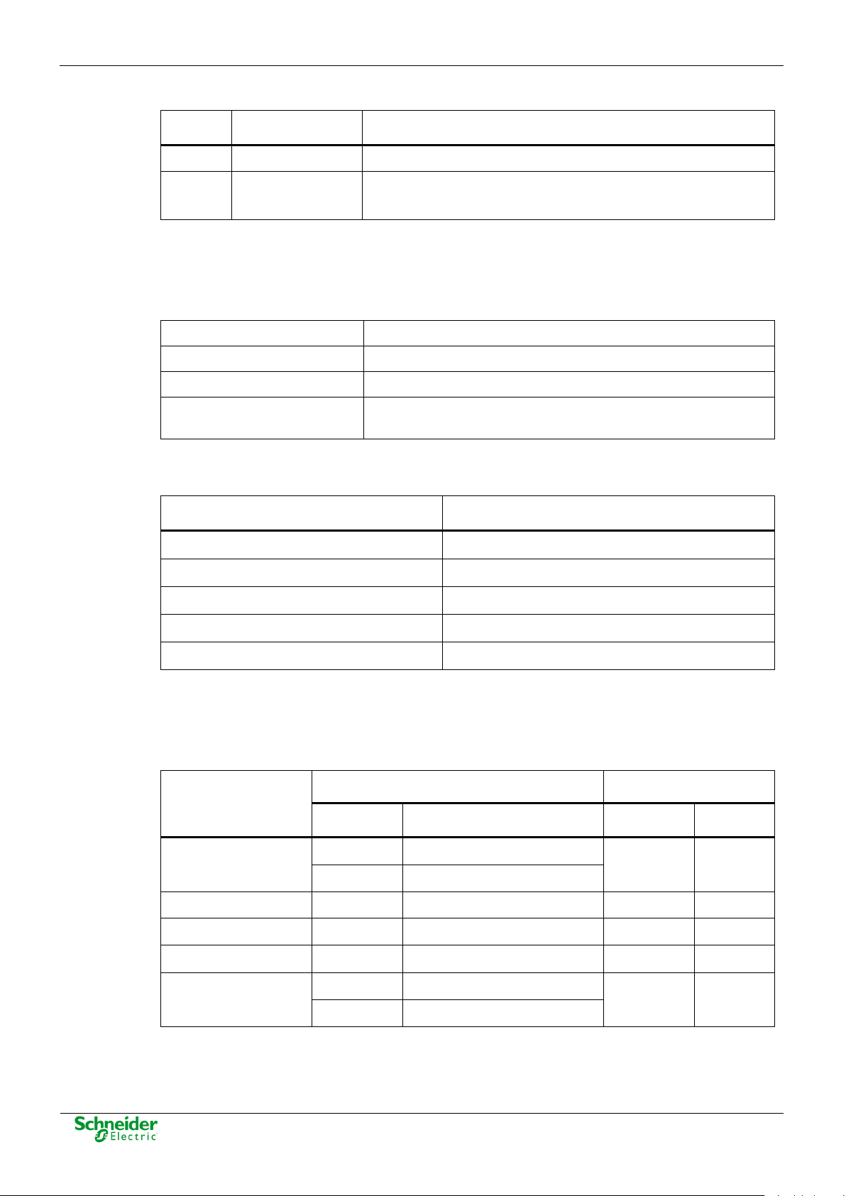
Reference Documents
Easergy Builder user manual FTE-S856-MSS
webAPP user manual FTE -S856-WPP
• Fixed some errors detected in previous version.
• Changed class and accuracy of the module.
SE-M562-USR
02 / 07-05-2020
AB_AC - User Manual _EN_02.pdf
Permanent throughout its validation period + 3 years after its
cancellation.
User Manual Document Code
webTool user manual FTE-S856-MSW
Saitel DR Platform user manual FTE-F800-USR
EOL Instructions FTE-EOLI-M562
Software Versions
The information in this manual is valid for the software versions listed below. This information is
also valid for later versions, although some parameters may change slightly:
Module
Baseline
Software AB_AC
RTU Software Easergy Builder (Plugin)
Module Version Plugin Version
Page 3

User Manual – AB_AC
07/05/2020
R&D Digital Seville
Page 3
Page 4

07/05/2020
User Manual – AB_AC
Page 4
R&D Digital Seville
Content
1 SAFETY & HEALTH .................................................................................................. 5
2 GENERAL DESCRIPTION OF AB_AC ................................................................... 16
3 PHYSICAL MOUNTING & INSTALLING ................................................................ 22
4 CONFIGURATION & MAINTENANCE .................................................................... 31
5 TECHNICAL SPECIFICATION TABLE ................................................................... 60
Page 5

User Manual – AB_AC
07/05/2020
R&D Digital Seville
Page 5
1 Safety & Health
Page 6

07/05/2020
User Manual – AB_AC
Page 6
R&D Digital Seville
Content
1 SAFETY & HEALTH .................................................................................................. 5
1.1 INTRODUCTION ........................................................................................................ 7
1.1.1 I
1.1.2 P
1.2 I
1.3 S
1.4 I
1.5 E
1.5.1 E
1.5.2 F
1.6 H
1.7 T
1.7.1 P
1.7.2 E
1.7.3 S
1.8 T
1.9 P
1.10 D
NFORMATION OF SECURITY .............................................................................. 7
RESENTATION ................................................................................................ 7
NTRODUCTION TO SAFETY ....................................................................................... 8
YMBOLS AND LABELS ON THE EQUIPMENT ............................................................. 9
NSTALLATION, SETUP AND OPERATION ................................................................... 9
ARTHING ............................................................................................................. 11
LECTRICAL SAFETY ...................................................................................... 11
UNCTIONAL EARTH (EMC) ............................................................................ 12
ANDLING ELECTRONIC COMPONENTS .................................................................. 13
ECHNICAL SPECIFICATIONS FOR SAFETY .............................................................. 13
ROTECTIVE ELEMENTS ................................................................................. 13
NVIRONMENTAL CONDITIONS ........................................................................ 13
TORAGE CONDITIONS ................................................................................... 13
ECHNICAL LABEL ................................................................................................. 14
ACKING AND UNPACKING ..................................................................................... 14
ECOMMISSIONING AND DISPOSAL ....................................................................... 15
Page 7

User Manual – AB_AC
07/05/2020
R&D Digital Seville
Page 7
symbol to avoid possible injuries.
DANGER indicates a hazardous situation which, if not avoided, will result in death or serious
WARNING
WARNING indicates a hazardous situation which, if not avoided, could result in death or
NOTICE
NOTICE is used to address practices not related to physical injury. The safety alert symbol shall
1.1 Introduction
1.1.1 Information of Security
Important information
Read these instructions carefully and look at the equipment to become familiar with the device
before trying to install, operate, service or maintain it. In this manual you can find different types of
messages associated with situations that have different level of risk for people and / or for the
equipment.
This symbol indicates "DANGER" or "WARNING". This symbol informs of an
electrical risk that will cause personal injuries if the instructions are not followed.
This symbol is associated to a safety alert. It is used to warn of possible personal
injury hazards. The user must follow all instructions or messages associated to this
DANGER
injury.
serious injury.
not be used with this signal word.
To Keep in Mind
Electrical equipment should be installed, operated, serviced, and maintained only by qualified
personnel. No responsibility is assumed by Schneider Electric for any consequences arising out of
the use of this material.
A qualified person is who fulfill with requirements in paragraph 1.2 .
1.1.2 Presentation
This manual provides information for a safe handling, commissioning and testing. This Safety
chapter also includes descriptions of the labels on the equipment.
Documentation for equipment ordered from Schneider Electric is dispatched separately from
manufactured goods and may not be received at the same time. Therefore, this guide is provided
to ensure that printed information which may be present on the equipment is fully understood by
the recipient.
The technical data in this safety guide is typical only, see the technical data section of the user
manual for specific details of a particular equipment.
Page 8
07/05/2020
User Manual – AB_AC
Page 8
R&D Digital Seville
Before carrying out any work on the equipment the user should be familiar with the
THE EQUIPMENT.
WARNING
Before working with the terminal of connection, the device must be turned off and disconnected
contents of this Safety chapter and the ratings on the equipment’s rating label.
THE SAFETY SECTION MUST BE READ BEFORE STARTING ANY WORK ON
1.2 Introduction to Safety
The information in the Safety Section of the equipment documentation is intended to ensure that
equipment is properly installed and handled in order to maintain it in a safe condition. It is assumed
that everyone who will be associated with the equipment will be familiar with the contents of that
Safety Section, or this manual.
When electrical equipment is in operation, dangerous voltages will be present in certain parts of the
equipment. Failure to observe warning notices, incorrect use, or improper use may endanger
personnel and equipment and also cause personal injury or physical damage.
of the feeding.
Proper and safe operation of the equipment depends on appropriate shipping and handling, proper
storage, installation and commissioning, and on careful operation, maintenance and servicing. For
this reason only qualified personnel may work on or operate the equipment.
Qualified personnel are individuals who:
• Have read and understood the information on the device and its user manual.
• Are familiar with the installation, commissioning, and operation of the equipment and of the
system to which it is being connected.
• Are able to safely perform switching operations in accordance with accepted safety engineering
practices and are authorized to energize and de-energize equipment and to isolate, ground,
and label it.
• Are trained in the care and use of safety apparatus in accordance with safety engineering
practices.
• Are trained in emergency procedures (first aid).
It is necessary to consider that the documentation of the device collects the instructions for its
installation, set up and operation. However, the manuals could not cover all the possible
circumstances neither include specific information on all the details.
In case of questions or specific problems, contact with his office of sales Schneider Electric or with
the center of attention to the customer and request the necessary information.
Page 9
User Manual – AB_AC
07/05/2020
R&D Digital Seville
Page 9
IEC symbol associated to a DANGER or WARNING
Symbol associated with a risk alert. The user must
ANSY symbol associated to a DANGER or
Protective earth
Associated symbol to the protective ground
Functional earth
Associated symbol to the functional ground
This symbol indicates that the equipment has been
This symbol indicates that, at the end of its life, this
The equipment has been designed and
Direct Voltage
Symbol of direct voltage (VDC).
Alternate Voltage
Symbol of alternate voltage (VAC).
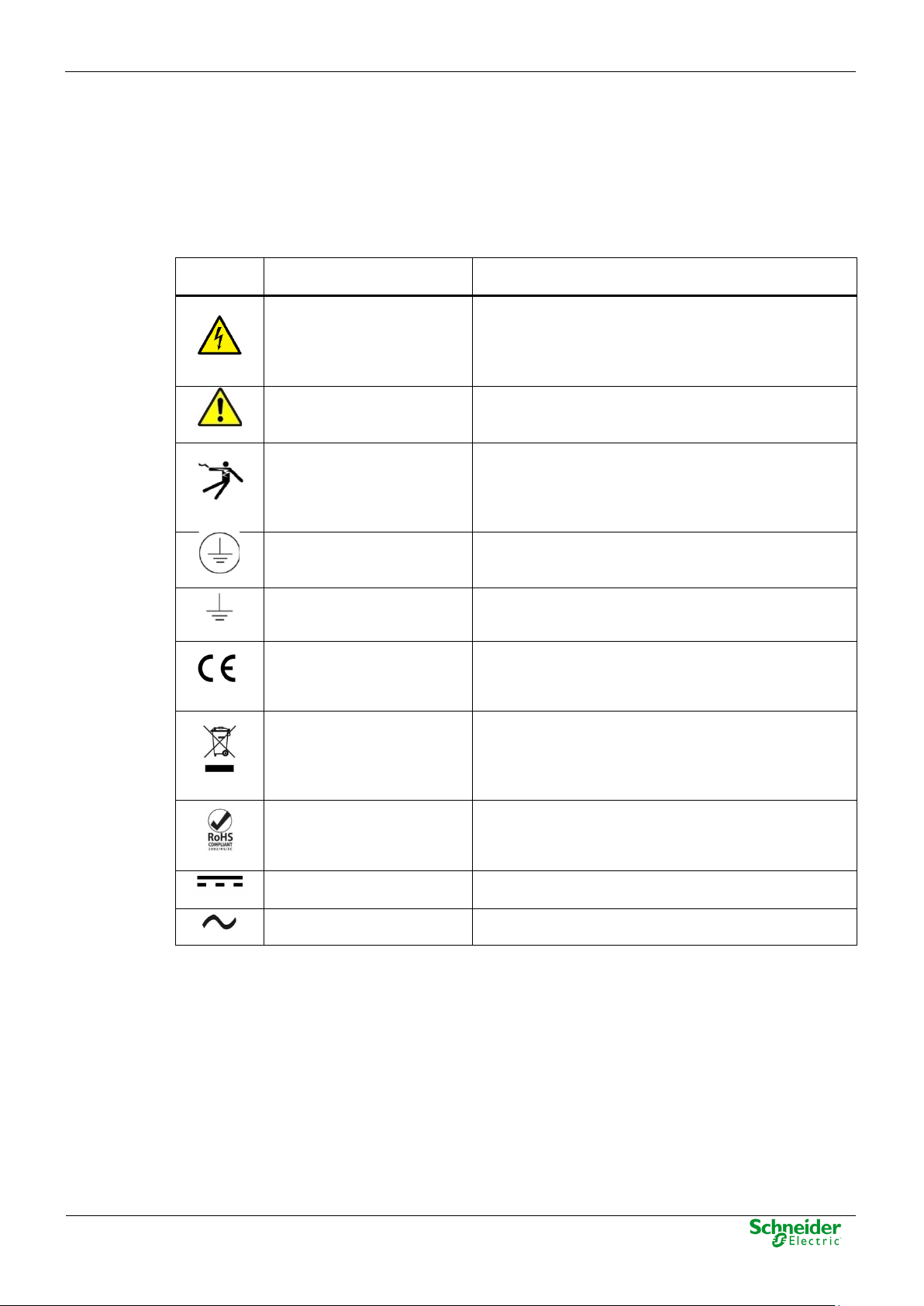
1.3 Symbols and Labels on the Equipment
For safety reasons the following symbols and external labels, which may be used on the equipment
or referred to in the equipment documentation, should be understood before the equipment is
installed or commissioned.
Table 1 – Symbols.
Symbol Associated Text Description
Possibility of electric
chock
Caution, read the manual.
Possibility of electric
chock
connection
connection
CE Mark
Electronic device. Special
instructions must be
follow for discard it.
message indicating that there is an electrical risk.
Failure to follow these instructions could cause
damage to people or death.
read the manual before handling the equipment.
WARNING message indicating that there is an
electrical risk. Failure to follow these instructions
could cause damage to people or death.
connection. See paragraph 1.5.1 in this manual.
connection. See paragraph 1.5.2 in this manual.
developed in compliance with all applicable
European Directives.
module must be discarded according to the WEEE
Directive (Waste Electrical and Electronic
Equipment).
Compliant with RoHS.
1.4 Installation, Setup and Operation
There are several acquisition blocks in Saitel DR that use dangerous tensions (> 50 V). The user is
responsible to check that the characteristics of each device are adapted and convenient for his
installation. The user should read the instructions of installation before proceeding to the use or
maintenance of the devices. Not following these instructions can be dangerous for the people and
the devices.
Not following these instructions can be dangerous for the people and the devices.
manufactured according to RoHS Directive
(Restriction of Hazardous Substances).
Page 10
07/05/2020
User Manual – AB_AC
Page 10
R&D Digital Seville
Devices that handle dangerous tensions are marked with a sticker on the front label (size: 12,5
WARNING
If this type of cabinet isn't available, a barrier must be installed in order to avoid an accidental
DANGER
mm). This label must be visible all the time while the module is installed on the DIN rail.
The following products handle dangerous tensions:
• HU120: High-performance CPU with acquisition (P/N M590xx000x).
• HU_AF: Advanced head unit with acquisition (P/N M503xx3x0x and P/N M503xx4x0x). For
other part numbers, depending on the voltage handled by the equipment connected to the
digital outputs (voltage > 50 V), this module must be marked with an electric risk label. It will
not be marked on factory.
• AB_DI: Digital inputs module (P/N: M55520000x, M55530000x and M55540000x).
• AB_DIDO: Input and output digital module (P/N M5722x000x, M5723x000x and M5724x000x).
For other part numbers, depending on the voltage handled by the equipment connected to the
digital outputs (voltage > 50 V), this module must be marked with a electric risk label. It will not
be marked on factory.
• AB_AC: Direct measurements module (P/N M562x0000x).
• AB_DO: This module does not handle high voltages, it will not be marked at the factory. This
module must be marked to inform about the risk when some equipment that manage voltage
higher than 50 V are connected to digital outputs.
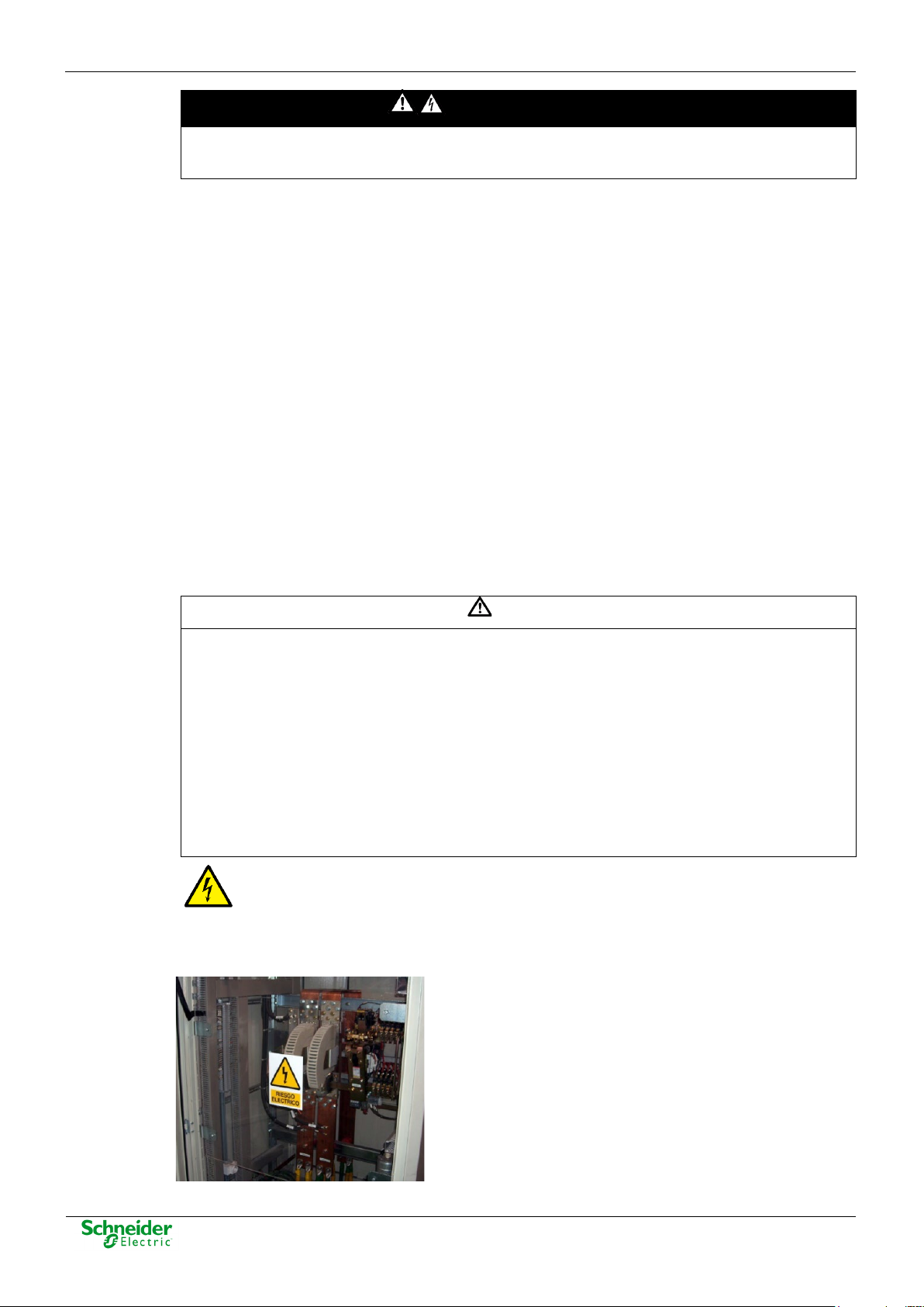
It is recommended to install the RTU inside a cabinet with a key. This cabinet only should be
opened by a qualified person.
contact with these dangerous elements. This barrier only should can be removed using a
special tool.
If the barrier has to be removed in order to access to equipment, personnel responsible for the
task must be sure that the barrier is installed again when the task is finished.
While the RTU is accessible for a user, all people must follow all instructions to prevent
electrical risk or discharges.
Not following these instructions can give like result that the device do not work properly
or even can damage to the people or devices.
An electrical risk symbol with enough size must be included on the cabinet’s door or
on the barrier.
The following image shows an example:
Figure 1 - Barrier of protection for elements with dangerous voltages.
Page 11
User Manual – AB_AC
07/05/2020
R&D Digital Seville
Page 11
NOTICE
Terminals will not be accessible to the user directly once it has made the installation of the
WARNING
Don’t use liquid products of cleanliness due to the presence of active parts.
WARNING
connected to this screw.
WARNING
All devices with high voltage must be disconnected before dismount a module from the DIN rail.
device. The cabinet will have to remain closed with key or the screen of installed protection.
The cabinet or installation must have a general switch placed just in the cable entry of the
installation (see paragraph 1.7.1 )
For the cleaning of the equipment, it is recommended to remove the power and to use only a dry
cloth by the surface when it detects excessive presence of dust or any element deposited on the
surface.
Because of the variety of uses of the product, the managers of the application and use of this
device of control will have to take the measures to ensure the fulfillment of all the requests of
security and provision of each application. The requests do reference to the applicable laws,
regulations, codes and standard.
1.5 Earthing
Before energizer the device, it has to be placed to earth properly such as it indicates in section
1.5 . When installing the device, ground is the first thing that should be connected and the last
one that should be disconnected.
Saitel can need put to earth for two distinct needs:
• For purposes of electrical safety (Protective Earth, PE).
• Improve the behavior in EMC and derive perturbations to earth (functional Earth).
1.5.1 Electrical Safety
Only qualified personnel, with knowledge about hazards associate with electrical equipment is
allowed to install Saitel DR. In general, the installation will be following IEC 61010-1
recommendations in order to be compliant with this norm.
The modules must be installed on a metallic DIN Rail which is fixed on a metallic
surface. This metallic surface must have an M4 screw marked with this symbol.
According to the norm IEC 61010-1, the ground of the cabinet or installation must be
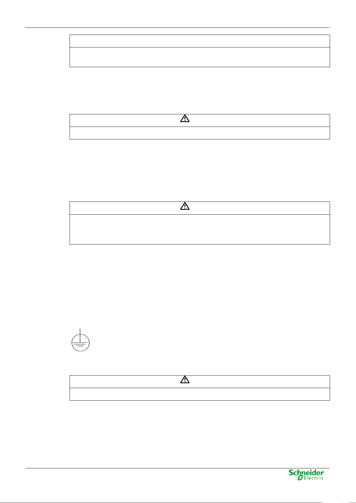
Saitel DR modules have a metallic enclosure offering protection for isolation faults. Earthing is
done by the metal rail fixing clip.
A dedicated connection with green/yellow wire should be used to have electric continuity to the
installation protective earth. Use a wire with adequate section according to IEC 61010.
Figure 2 - Yellow and Green cable for earthing.
Page 12
07/05/2020
User Manual – AB_AC
Page 12
R&D Digital Seville
WARNING
According to Electrical Safety:
NOTICE
The DIN rail must have terminals of earthing (of yellow and green color) necessary to connect
The design and installation of the cabinet is responsible for compliance with all the existing
international and national electrical codes concerning protective grounding of any device.
• The screw for ground must be exclusive for this use.
• The power voltage must be supplied by a power supply that offers double or reinforced
insulation against high voltages (higher than 50 V).
1.5.2 Functional Earth (EMC)
In this case the main rule is that the connection has to do with wires of the lower possible length to
the screen or connection of put to earth nearer. In this case the section of the driver is not notable,
is more, it advises that the use of flat wires or flexible conductive bands for a good behavior EMC.
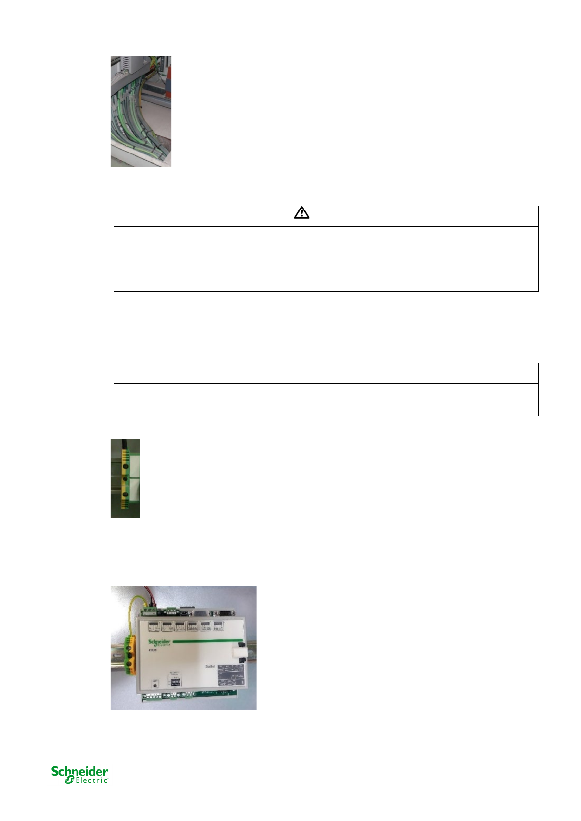
the terminals of PE (if it is present).
Figure 3 - Terminal for functional earth (EMC).
All Saitel DR modules with power or polarization connector have an exclusive terminal for earthing
EMC. These modules are HU120, HUe, HU_A, HU_AF, XU, AB_DO, AB_DIDO and AB_SER with
external polarization.
Figure 4 - Example of earthing for EMC.
Page 13
User Manual – AB_AC
07/05/2020
R&D Digital Seville
Page 13
WARNING
The enclosure ONLY should be removed when is strictly necessary, because this action has a
WARNING
The connection / disconnection switch must be installed in a fixed element (for example the wall
WARNING
This equipment has been designed ONLY for indoor use.
1.6 Handling Electronic Components
Like any electronic device, Saitel is susceptible to receive electrostatic discharges during the
handling. It is necessary to take the usual measures to minimize this risk, since serious damage to
the equipment can be caused, which may not be detected immediately but which may affect the
reliability of the product.
risk for the equipment:
• Before removing the enclosure, the operator must be equipotential with the equipment.
• Avoid touching the electronic. The board must be always manipulated for the edges.
• If the equipment has to be passed between two persons, both must be equipotential.
• Put the module always on an antistatic surface or on a surface equipotential with you.
• During the storage and transport, the module will remain in the packaging.
Not following these instructions can give like result that the device do not work properly
or even can damage to the people or devices.
1.7 Technical Specifications for Safety
1.7.1 Protective Elements
The cabinet's engineering and installation must include a general automatic switch next to the
cables' input in the cabinet; once the door is opened, high voltages must be interrupted inside. This
switch must be located at a place which is not accessible by a third person while the operator is
using the boards in the cabinet.
Moreover, the installation will incorporate a circuit breaker of 5A next to the cabinet protecting it
from possible overcurrent in the power supply.
Both switches will be labeled with the symbol O as "Off" and I as “On”.
of the cabinet) and it mustn’t break any earthing wire.
1.7.2 Environmental Conditions
The protection degree of the device is IP20.
If it is necessary for his use in some external surroundings, it has to mount in a cabinet or specific
accommodation that contributes a degree of protection IP54, protected against the dust and water.
The electronic cards of the modules will be able to be tropicalized or no according to the option of
setting chosen. The tropicalized used is the AVR80, of the company ABchimie. It can consult all the
technical information of this type of finishing in http://www.abchimie.com/
Other data to take into account about the environmental are:
.
Page 14

07/05/2020
User Manual – AB_AC
Page 14
R&D Digital Seville
WARNING
According to the standard 60950-1, all electrical safety tests have been done in an
NOTICE
On the “Technical data” zone, you can see relevant information about the input and output
• Altitude until 2000 m.
• Operation temperature range: Between -40 ºC and 70 ºC. (IEC 60068-2-1 and IEC 60068-2-2).
environmental temperature range of -40 ºC to 60 ºC. For higher temperature (> 60 ºC), the
module must be handled with care, since the metal surface could reach a dangerous
temperature for the user.
• Maximum relative humidity of 95%. (IEC 60068-2-30)
• Degree of pollution II. (IEC 60255-5)
• Overvoltage transitory until levels of Category III. (IEC 60255-5)
1.7.3 Storage Conditions
The continuous exhibition to some high levels of humidity during the storage can cause damages
to the electronic components and reduce the useful life of the device.
We recommend that, in the enclosure of storage, the relative humidity do not exceed 50%.
Before the installation of an electrical equipment, it is recommended to leave the necessary time for
the acclimatization of the environmental temperature.
1.8 Technical Label
Each Saitel product includes a technical label with the following information:
Figure 5 - Technical label.
voltage in the module. Any voltage greater than 50 V must be consider as a high voltage.
1.9 Packing and Unpacking
All Saitel modules are packaged separately in their own carton box and shipped inside outer
packaging. Use special care when unpacking the device. Don’t use force.
Page 15

User Manual – AB_AC
07/05/2020
R&D Digital Seville
Page 15
NOTICE
Our products leave our factory in closed, sealed original packaging. If at receipt of the delivery
the other elements, and each one must be recycled according to the local regulation.
the transport packaging is open or the seal is broken, the confidentiality and authenticity of the
information contained in the products cannot be ensured.
The design revision and manufacturing options can be determined using the P/N included in the
packaging label on packaging.
After unpacking the device, inspect it visually to be sure it is in proper mechanical condition.
If the product needs to be shipped, the original packaging must be used, including foams and the
carton box. If the original packaging is no longer available, make sure that the packaging used is
according to ISO 2248 specifications for a drop height 1 m.
1.10 Decommissioning and Disposal
When the product is marked with this symbol, it means that, at the end of its life
cycle, you mustn't dispose the product together with habitual residues. To avoid the
possible damage to the environment or to the human health that represents the
uncontrolled elimination of residues, please, separate the battery (if there is one) of
Page 16

07/05/2020
User Manual – AB_AC
Page 16
R&D Digital Seville
2 General Description of AB_AC
Page 17

User Manual – AB_AC
07/05/2020
R&D Digital Seville
Page 17
Content
2 GENERAL DESCRIPTION OF AB_AC ................................................................... 16
2.1 SAITEL DR PLATFORM ........................................................................................... 18
2.2 AB_AC
2.3 I
NTERFACES .......................................................................................................... 20
2.4 H
ARDWARE ARCHITECTURE ................................................................................... 20
FUNCTIONS .............................................................................................. 18
Page 18
07/05/2020
User Manual – AB_AC
Page 18
R&D Digital Seville
WARNING
Please note Saitel DR does not support hot-swapping, that is, module replacements during
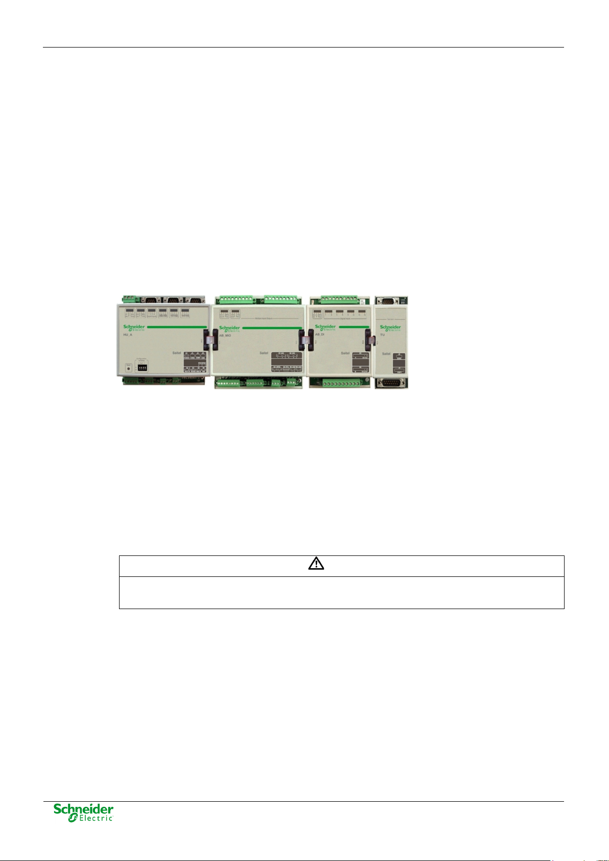
2.1 Saitel DR Platform
Saitel DR is a hardware platform by Schneider Electric. It consists of a set of equipment which
have been specifically designed for real-time control and automation applications. Saitel DR is a
high-technology platform which serves Schneider Electric’s business areas.
On this hardware platform, the Baseline Software Platform is installed. This software is used in
Saitel families (Saitel DP and Saitel DR) and other Schneider Electric products.
Other features identifying Saitel DR are:
• A DIN rail is used for the mechanical installation.
• The communication between the controls units integrated in a distributed system is mainly
established by Ethernet.
• The terminal blocks for field-connection are completely built into acquisition blocks.
Figure 6 - Saitel DR.
Saitel DR’s design has been optimized to meet the most demanding requirements of multiple
sectors:
• Safety and reliability requirements for power, gas and water supply, as well as sewage
treatment plants, etc.
• Compliance with electric safety, electromagnetic compatibility, and environmental standards.
• Centralized monitoring and control of geographically-distributed systems which support
hierarchical data acquisition and sharing networks.
• Local monitoring and control with data sharing capabilities of plant-distributed equipments.
• Quick troubleshooting, including the possibility of using programmable automation execution.
operation.
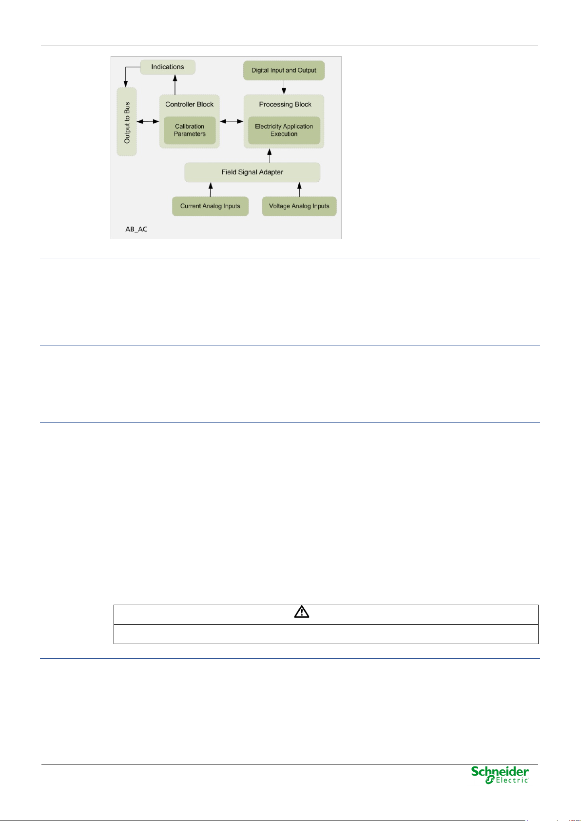
2.2 AB_AC Functions
The AB_AC module is used for magnitudes measurements in alternating current networks and for
energy measurements. This module performs, as well, other typical functions in transmission and
distribution networks, for instance, synchronism checking between two power lines
(Synchrocheck).
The diagram below illustrates the functional block diagram:
Figure 7 - Functional block diagram.
Page 19
User Manual – AB_AC
07/05/2020
R&D Digital Seville
Page 19
WARNING
If a calibration is performed on the channels, the factory calibration will be deleted.
Power Supply
The AB_AC module receives its power supply through the CAN communications bus.
Through this general power supply, the polarization is supplied internally to the digital inputs and
outputs.
The AB_AC module has a consumption of 2 W at 25 ºC.
Digital Input and Output
The direct measurement module integrates a digital input and a digital output with the adequate
protection elements.
Currently, these two signals are reserved for Synchrocheck aplication, so if this functionality is not
selected, neither the input or the output should be wired.
Analog Inputs
The AB_AC module allows connecting:
• 3 independent voltage inputs.
• 3 independent current inputs.
• An additional input for the neutral current line.
All signals are connected usin 2-wire connectors.
The system allows processing signals for a nominal frequency of 50 or 60Hz. The user can select
the frequency using Easergy Builder.
Each channel is protected separately against electromagnetic disturbances.
The user can calibrate these channels using the console connection available in all HU types and
Saitel Webtool (only advanced HUs).
Field Signals Adaptation Block
This block contains all the required elements to adapt the field signals to the value ranges used by
this processing unit. It also provides the required protection elements for the galvanic isolation of
each channel.
Technical data for A1 ordering options are specified in chapter “5 Technical Specification Table”.
Other values are available, upon request.
Page 20
07/05/2020
User Manual – AB_AC
Page 20
R&D Digital Seville
Processing Block
The processing block filters the analog signals coming from the adaptation block and, then, it
digitalizes them at a 6.4 kHz frequency (for a 50Hz electric line frequency) and at a 7.68 kHz
frequency (for a 60 Hz electric line frequency).
Control Block
This block manages the communications through the internal bus, as well as the storage of the
module´s calibration parameters.
2.3 Interfaces
Following interfaces are available in this module:
• 1 removable terminal block to connect three voltage inputs.
• 1 removable terminal block to connect one digital output.
• 1 removable terminal block to connect one digital input.
• 1 screw terminal block to connect three current inputs and one neutral (homopolar) current.
• 8 LED indicators.
Figure 8 - AB_AC - Front panel.
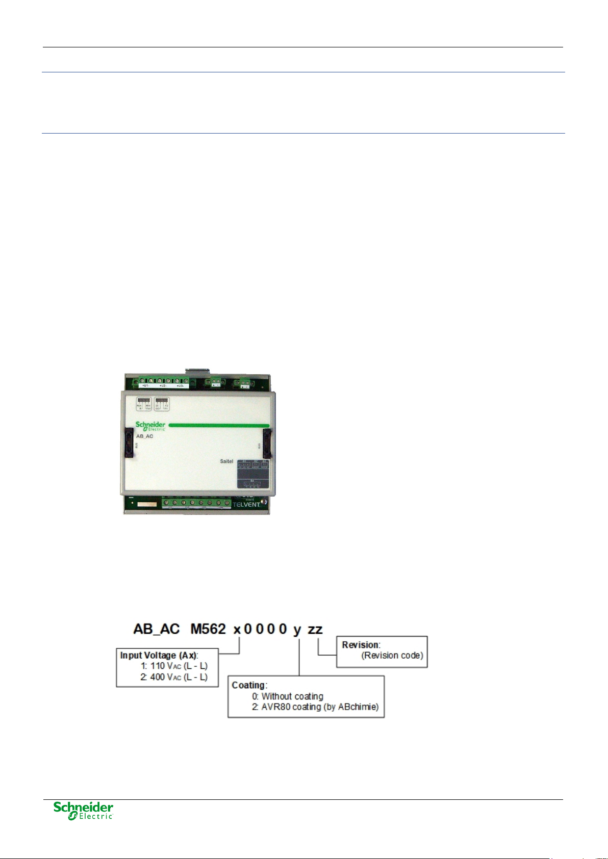
2.4 Hardware Architecture
The P/N for this module is the following one:
Figure 9 - AB_AC P/N.
Ordering options:
• (A1) Voltage Inputs: 110 V
• (A2) Voltage Inputs: 400 V
(Phase – Phase).
AC
(Phase – Phase).
AC
Page 21
User Manual – AB_AC
07/05/2020
R&D Digital Seville
Page 21
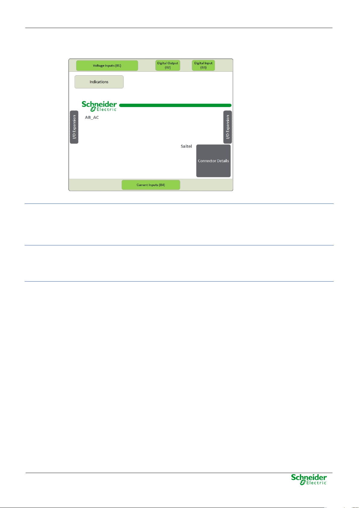
Indicators
The following figure illustrates the AB_AC hardware blocks diagram:
Figure 10 - AB_AC - Hardware blocks diagram
There are 8 LED indicators on the module’s front panel which provide information about the module
and the features.
Section 3.3 provides detailed information about the operation of each LED.
Voltage Inputs (B1) and Current (B4) Inputs
Both voltage and current inputs are connected to the module by means of screw terminals. The B1
terminal block includes six terminals: two for each voltage input whereas the B4 terminal block
includes eight terminals: two for each phase current and the remaining two for the neutral current
Digital Input and Output (B2 and B3)
• The digital output is a voltage free contact.
• The digital input is only for syncrocheck applications and must be polarized with 24 V.
These terminal blocks are only used with Synchrocheck. There are several options to wire them to
signals. Project’s engineers should analyze each option to apply the best solution, according the
advantages and disadvantages of each option.
Page 22

07/05/2020
User Manual – AB_AC
Page 22
R&D Digital Seville
3 Physical Mounting & Installing
Page 23

User Manual – AB_AC
07/05/2020
R&D Digital Seville
Page 23
Content
3 PHYSICAL MOUNTING & INSTALLING ................................................................ 22
3.1 INSTALLATION ....................................................................................................... 24
3.1.1 H
3.1.2 M
3.1.3 P
3.1.4 M
3.2 W
3.2.1 W
3.2.2 B
3.2.3 S
3.3 LED
ANDLING ...................................................................................................... 24
ODULE LOCATION IN THE ITB ....................................................................... 24
OWER SUPPLY REQUIREMENTS .................................................................... 24
OUNT AND DISMOUNT PROCEDURES ............................................................ 24
IRING AB_AC .................................................................................................... 26
IRING RECOMMENDATIONS .......................................................................... 26
ASIC APPLICATION WIRING ........................................................................... 26
YNCHROCHECK WIRING ................................................................................ 26
INDICATORS ................................................................................................... 29
Page 24

07/05/2020
User Manual – AB_AC
Page 24
R&D Digital Seville
The module AB_AC has hazard of electric shock, electric arc or burns. For any of these
WARNING
An electrostatic discharge might degrade electronic components or cause permanent damages.
WARNING
It is important to assure that handling is always done while the ITB elements are unpowered.
3.1 Installation
3.1.1 Handling
cases, follow these instructions:
• Only qualified operator should install this equipment. Such work should be performed only
after reading this entire set of instructions and checking the technical characteristics of the
device.
• NEVER work alone.
• Turn off all power supplying this equipment before working on or inside it. Consider all
sources of power, including the possibility of back feeding.
• Always use a properly rated voltage sensing device to confirm that all power is off.
• Start by connecting the device to the protective ground and to the functional ground.
• Screw tight all terminals, even those not in use.
Failure to follow these instructions will result in death or serious injury.
DANGER
To avoid electrostatic damage, the following precautions must be strictly followed:
• Do not touch the bus connector pins.
• If unused, keep the modules in the antistatic bag.
3.1.2 Module Location in the ITB
There is not special considerations for locating this module in the ITB.
3.1.3 Power Supply Requirements
To calculate the cabinet’s power supply requirements, you will need to consider the power
consumption of each module. The modules’ power consumptions must be added plus a safety
margin (min. 20%).
In order to avoid ITB overload, the power supply performance should also be considered (typically,
70-90%).
The power consumption data is detailed in the technical specifications table of each module.
3.1.4 Mount and Dismount Procedures
Don’t remove the flat ribbon while the ITB is powered.
All Saitel DR modules have a DIN-rail bracket at the rear side that allows mounting on a DIN rail:
Page 25

User Manual – AB_AC
07/05/2020
R&D Digital Seville
Page 25
Figure 11 - DIN rail
The mounting procedure is described below:
• Switch off the power supply.
• Attach the module’s rear bracket on the upper DIN rail.
• Press the lower front panel gently until a click confirms that the bracket is fit on the rail.
• Verifying the module is anchored firmly to the rail, although lateral movement is possible.
Figure 12 - Mounted
The module is dismounted from the DIN rail as follows:
• Switch off the power supply.
• If necessary, disconnect the bridge(s) connecting the module to the system bus.
• Holding the module by the front panel, push the upper metal tab downward. The user can
also pull the tab down using for example a screwdriver as shown in
Figure 13 - Dismount
• Pressing the tab, remove the module from the lower DIN rail.
• Once detached, the module can be removed easily.
Page 26

07/05/2020
User Manual – AB_AC
Page 26
R&D Digital Seville
NOTICE
As shown in the figure previous, the neutral wire is not wired. These pines are reserved for use
NOTICE
When Synchrocheck functionality is selected in the module, the current inputs (B4) will not be
3.2 Wiring AB_AC
3.2.1 Wiring Recommendations
The following table shows several wiring recommendations for signals, communications and power:
Table 2 - Wiring recommendation
Voltage Inputs 7 mm
Current Inputs 7 mm
Digital input 7 mm
Digital output 7 mm
3.2.2 Basic Application Wiring
If the direct measurements module is installed to acquire voltage and current measurements, the
only required wiring includes the terminal blocks for voltage and current inputs.
Voltage inputs are labeled as Vx whereas current inputs are labeled as Cx. The figure below
illustrates the wiring for B1 and B4 terminal blocks:
Figure 14 - Basic Application – B1 and B4 terminal blocks wiring.
2.5 mm²
13 AWG
2.5 mm²
13 AWG
1.5 mm²
15 AWG
1.5 mm²
15 AWG
0.5 Nm Copper
0.5 Nm Copper
0.5 Nm
Copper,
shielded
0.5 Nm Copper
Type of wire
in other applications.
3.2.3 Synchrocheck Wiring
used and, only the first two voltage inputs should be connected. You will need to wire both the
digital input (B3) and the digital output (B2).
The figure below illustrates the B1 wiring:
Page 27

User Manual – AB_AC
07/05/2020
R&D Digital Seville
Page 27
NOTICE
Figure 15 - Synchrocheck application – B1 terminal block wiring.
There are several options to implement the Synchrocheck functionality. The project’s engineers
should analyze them to apply the best solution.
Command from an AB_DO
The close command is transmitted from the relay contacts of an AB_DO.
Figure 16 - Synchrocheck application – Close command by the AB_DO.
In this case, Synchrocheck operates as follows:
The AB_DO module will execute the close command only when the signal CLOSURE_ENA
defined in coreDb is 1, indicating that both lines are in optimal conditions of synchronism.
The direct measurements module triggers the digital output at the same time that activates
CLOSURE_ENA in coreDb. The output signal will remain active, while synchronism conditions are
satisfied or the switch closure has not been detected.
When any synchronism condition fails, the direct measurements module will deactivate the digital
output , so the signal CLOSURE_ENA will be set to 0 in coreDb; therefore, the digital output will not
be activated by the AB_DO.
• Advantages:
o The close command is completely safe, since the commands transmitted from an
AB_DO are supervised. Thus, the generation of unwanted commands due to a
simple failure is not possible.
• Disadvantages:
o The command is conditioned by the bus management delay, database management,
logic programs, etc, so a slight and random delay might occur, even though this delay
is admissible in most cases. There are also configurable time parameters that can be
adjusted to the output activation relay.
o The presence of an AB_DO module is required.
Page 28

07/05/2020
User Manual – AB_AC
Page 28
R&D Digital Seville
It is important to note that we have to define in coreDb the CLOSURE_ENA signal. We must
always configure the required times for the correct function of this mechanism).
Command from the AB_AC module DO
The close command is transmitted directly from the relay contacts connected to the existing
AB_AC digital output.
Figure 17 - Sychrocheck application – Close command by the AB_AC.
When relay closure conditions are satisfied, the direct measurements module will activate the
digital output which is directly wired to the relay. At the time that any of the conditions of
synchronism fails or the relay is closed, the module will disable this signal.
• Advantages:
o The delays since the synchronism condition is satisfied until the relay is enabled are
minimal. This delay corresponds basically with the relay delay itself, so it is a
determinist delay. This time can be included in the configuration parameters, in order
to advance the output activation to correct for the relay delay.
o An additional AB_DO module is not required.
• Disadvantages:
o The AB_AC digital output does not integrate the sophisticated security method
available in the AB_DO outputs. Although very unlikely, a fail in the transistor when
short-circuited may generate a close command in unwanted situations. When the
output is connected to the digital input, if a fault occurs on the output, an alarm will be
activated, although it is the user who should take appropriate actions.
Combined Command (AB_DO + DO of AB_AC Module)
In this case, the two outputs, AB_DO and AB_AC modules, will be wired serially.
Figure 18 - Synchrocheck application – Close command by the AB_AC and AB_DO.
When optimal synchronism conditions are satisfied, the direct measurements module’s contact will
close and this will activate the signal CLOSURE_ENA in coreDb. Only if a close command is
Page 29

User Manual – AB_AC
07/05/2020
R&D Digital Seville
Page 29
NOTICE
This is the most recommendable option, especially if there is in the system any AB_DO with a
R
received from the AB_DO during the time when CLOSURE_ENA remains active, the command will
be completed and the switch will close.
While the AB_AC digital output is open, a close command cannot be executed from the AB_DO.
• Advantages:
o The command is very safe, as the condition is transmitted by an AB_DO command.
o The delay between the optimal condition of synchronism and the relay (AB_DO)
triggering is practically zero if the delay introduced by this relay was indicated in its
corresponding configuration parameter.
• Disadvantages:
o The presence of an AB_DO module is required.
free output.
3.3 LED Indicators
The AB_AC module integrates the following indicators on the front panel:
Blinking
On
Off
Table 3 - LED indicators
LED State Description Recommended action
Run
Module working properly
Module without enough power Connect the CPU to a
correct power supply.
Not used
Fail
AB not configured or in abnormal state Configure AB_AC properly
with Easergy Builder
Failure in EEPROM
Not fail has been detected in the module
Mnt
The module is in maintenance (Flashing, addressing)
It may also indicate that the module has lost calibration
values or has not been calibrated.
For software versions 02.00.15 (AT90CAN) / 02.00.06
(DSP) and later homopolar current in not calibrated.
Homopolar current must be
calibrated.
The module is in operation
DI
Active digital input (DSP)
Inactive digital input (DSP)
DO
Synchrocheck
Closure enabled
(CLOSURE_ENA=1)
Basic application Active digital output (DSP)
Page 30

07/05/2020
User Manual – AB_AC
Page 30
R&D Digital Seville
LED State Description Recommended action
F1
F2
Synchrocheck
Closure disabled
(CLOSURE_ENA<>1)
Basic application Inactive digital output (DSP)
On firmware upgrade Upgrade completed
Undervoltage detected.
Synchrocheck
(DEATH_R DEATH_S=1 or
UNDERV=1)
On firmware upgrade Upgrading in progress
Undervoltage not detected
Synchrocheck
DEATH_R DEATH_S and
UNDERV <> 1
On firmware upgrade Upgrade completed
Synchrocheck Synchronism condition detected
On calibration Calibration in progress
On firmware upgrade Upgrading in progress
On calibration Calibration completed
Don’t disconnect the
module
Don’t finish the injection
with the signal generator
Don’t disconnect the
module
Synchrocheck
Synchronism condition not
detected
Page 31

4 Configuration & Maintenance
Page 32

07/05/2020
User Manual – AB_AC
Page 32
R&D Digital Seville
Content
4 CONFIGURATION & MAINTENANCE .................................................................... 31
4.1 ITB CONFIGURATION ............................................................................................. 33
4.2 M
4.3 M
4.4 F
4.5 C
ODULE CONFIGURATION ...................................................................................... 35
4.2.1 B
4.2.2 S
4.3.1
4.3.2 U
4.3.3 U
4.5.1 W
4.5.2 C
4.5.3
4.5.4
ASIC APPLICATION ........................................................................................ 36
YCHROCHECK .............................................................................................. 40
AINTENANCE OF MODULE VIA WEB ..................................................................... 44
WEBAPP VS WEBTOOL .................................................................................... 44
SING WEBAPP .............................................................................................. 45
SING WEBTOOL ............................................................................................ 48
IRMWARE UPDATE ............................................................................................... 52
ALIBRATION ........................................................................................................ 54
IRING FOR CALIBRATION .............................................................................. 55
ONSOLE TERMINAL ....................................................................................... 56
WEBTOOL ...................................................................................................... 57
WEBAPP ........................................................................................................ 58
Page 33

User Manual – AB_AC
07/05/2020
R&D Digital Seville
Page 33
NOTICE
To perform the operations described in this chapter, the user must be familiar with the Easergy
4.1 ITB Configuration
Builder tool. Otherwise, please refer to the tool's manual.
In the Workspace of Easergy Builder, create a new RTU using button or pressing right button
of the mouse in an empty area of the RTUs tree:
Figure 19 - Adding new RTU.
Pressing button next to the graphical ITB, you can add, remove or change the I/O modules
included on the default configuration.
The user needs understand some basic concepts about Saitel DR before configuring the
acquisition:
• An ITB is a set of acquisition blocks connected to a CPU (HU).
• An Acquisition Block or AB is a Saitel DR input/output module.
• Each acquisition block is allocated to a unique address in the ITB, the Node Number; this
number identifies both the module and its I/O points. In the case of HU_AF and HU_BI, the HU
has also a node number assigned (In this case, the HU node will take address number 1 and
cannot be changed).
• The procedure AAP (Automatic Addressing Procedure) is performed by the operator every
time an AB module is added, deleted, replaced or moved inside the ITB. It can be launched
manually or automatically by setting switch #3 in the HU module to auto (please, refer to “Saitel
DR Modules Manual”).
Figure 20 - Acquisition modules in a default configuration.
The number between parentheses next to each module's name is the node number. You can
select an AB and use buttons to change its physical position.
When “Auto Address” box is checked (by default), if you reorder, add or delete an AB, all
addresses are automatically recalculated matching their physical position in the rail. Address
number 1 is assigned to the AB closest to the HU module (for HU_AF or HU_BI, address number 1
will be attached to the HU itself).
If “Auto Address” box is unchecked, modules will retain the allocated address, ignoring any
changes made. If rechecked, the following message will appear:
Page 34

07/05/2020
User Manual – AB_AC
Page 34
R&D Digital Seville
Figure 21 - Confirmation for automatic addressing.
Select an AB (click on the AB image) and use button to remove it.
Use button to add a new AB. Select the type of AB in the following window:
Figure 22 - Adding one (or several) AB.
If “Auto Address” is checked, you can add several AB at one time. This window allows selecting
the quantity of modules to be added. If “Auto Address” in unchecked, you only can add one AB
each time and you have to select the address to be assigned.
To create a new configuration, select RTU in the tree and pulse right button of the mouse or use
button.
Figure 23 - Adding new configuration.
If the field "Create acquisition points defined in the RTU" is marked, all points of the local
acquisition of the acquisition blocks included in the default acquisition configuration associated with
the RTU will be included in coreDb.
For example, if a HUe has an ITB with a AB_AO module, if "Create acquisition points defined in
the RTU", following points are generated:
• 4 digital inputs in Status table.
• 4 analog outputs in Setpoint table.
• The supervision points of each AB module.
At the end of the operation, the new configuration will appear in the RTUs tree. We double-click on
it, and the Easergy Builder tool goes into Configuration mode.
Figure 24 - Configuration screen.
Page 35

User Manual – AB_AC
07/05/2020
R&D Digital Seville
Page 35
NOTICE
The graphical interface does not take into account if the ITB is assembled in one or multiple
Within the configuration, pressing double in claq we can change the address of the modules again.
4.2 Module Configuration
The local acquisition Device for Saitel DR is named “claq”. The main functionality of the Local
Acquisition Device Controller is supporting the communication between the inputs and the outputs
managed by the acquisition blocks and coreDb points.
The first step to configure the acquisition settings is assembling the ITB in the graphical interface,
including both the HU and the acquisition blocks in the same order as they are physically installed
in the DIN rail.
rows. The modules should always be added in the adequate order, regardless the number of
TU-XU modules that we have installed.
Currently, the following applications for AB_AC module are available:
• Basic application: The calculation of electrical measurements (voltage, current, power and
energy measurements).
• Synchrocheck. This application monitors and controls the status of a switch based on certain
conditions of synchronism.
These applications can be chosen in Easergy Builder when AB_AC is selected:
Figure 25 - New slave Saitel DR acquisition.
Applications cannot operate simultaneously in the same module.
Figure 26 - AB_AC module applications.
Page 36

07/05/2020
User Manual – AB_AC
Page 36
R&D Digital Seville
4.2.1 Basic Application
The basic application allows the calculation of electrical measurements (voltage, current, power
and energy measurements).
Figure 27 - AB_AC Basic Application.
Figure 28 - Basic application setting.
The configurable parameters for the basic application are:
Table 4 – Parameters for AB_AC (Power).
Page 37

User Manual – AB_AC
07/05/2020
R&D Digital Seville
Page 37
Identifier Name Description Default Value
ID:0 ID license ID configuration ID Configuration Menu
(button Configuration)
ID:21 Power. Reset Energy
Reset of the energy counters 0
Counters
ID:48
Voltage Transformer Ratio
(V:1)
ID:49 Phase Current Transformer
Ratio (A:1)
ID:50
Neutral Current
Transformer Ratio (A:1)
Ratio of external voltage transformer
(transducer) if applicable.
Ratio of an external phase current
transformer (transducer) if applicable
Ratio of an external homopolar
current transformer (transducer) if
100
100
100
applicable
ID configuration menu allows to configure the following features:
• Frequency: Define the power system frequency. (50Hz or 60Hz)
• INFIELD: Define the analog input filed connection topology.
o Element connection: 3 phase-neutral voltages Va, Vb, Vc and 3 phase currents Ia, Ib,
Ic.
o 3+1 elements connection: 3 phase-neutral voltages Va, Vb, Vc, 3 phase currents Ia,
Ib, Ic and the neutral current.
• PPS: Activate the acquisition of the internal PPS source provided by CAN bus for signal
acquistion
Sampling mode selection is not used in AB_AC current version.
Figure 29 - ID configuration.
Table 5 – Measurements in coreDb of AB_AC (Power).
Page 38

07/05/2020
User Manual – AB_AC
Page 38
R&D Digital Seville
Measure Description
VRrms Power. VRrms - Effective voltage R
VSrms Power. VSrms - Effective voltage S
VTrms Power. VTrms - Effective voltage T
IRrms Power. IRrms - Effective current R
ISrms Power. ISrms - Effective current S
ITrms Power. ITrms - Effective current T
AR Power. AR - Apparent power R
PR Power. PR - Active power R
QR Power. QR - Reactive power R
AS Power. AS - Apparent power S
PS Power. PS - Active power S
QS Power. QS - Reactive power S
AT Power. AT - Apparent power T
PT Power. PT - Active power T
QT Power. QT - Reactive power T
A3phase Power. A3Phase - Three-phase apparent power
P3phase Power. P3Phase - Three-phase active power
Q3phase Power. Q3Phase - Three-phase reactive power
VRS Power. VRS - Phase-Phase voltage R-S
VRT Power. VRT - Phase-Phase voltage R-T
VST Power. VST - Phase-Phase voltage S-T
Freq Power. Freq - Frequency
PFR Power. PFR - Power factor R
PFS Power. PFS - Power factor S
PFT Power. PFT - Power factor T
VNrms Power. VNrms - Effective voltage N
INrms Power. INrms - Effective current N (Direct input)
VRphase Power. VRPhase - Voltage displacement R
VSphase Power. VSPhase - Voltage displacement S
VTphase Power. VTPhase - Voltage displacement T
VNphase Power. VNPhase - Voltage displacement N
IRphase Power. IRPhase - Current displacement R
ISphase Power. ISPhase - Current displacement S
ITphase Power. ITPhase - Current displacement T
INphase Power. INPhase - Current displacement N (Direct input)
VRsec Power. VRsec - Secondary effective voltage R
VSsec Power. VSsec - Secondary effective voltage S
VTsec Power. VTsec - Secondary effective voltage T
Page 39

User Manual – AB_AC
07/05/2020
R&D Digital Seville
Page 39
Measure Description
VNsec Power. VNsec - Secondary effective voltage N
IRsec Power. IRsec: Secondary effective current R
ISsec Power. ISsec: Secondary effective current S
ITsec Power. ITsec: Secondary effective current T
INsec Power. INsec: Secondary effective current N
ERin Power. ERin - Active energy demand R
ERout Power. ERout - Active energy supply R
ERL Power. ERL - Inductive energy R
ERC Power. ERC - Capacitive energy R
ESin Power. ESin - Active energy demand S
ESout Power. ESout - Active energy supply S
ESL Power. ESL - Inductive energy S
ESC Power. ESC - Capacitive energy S
ETin Power. ETin - Active energy demand T
ETout Power. ETout - Active energy supply T
ETL Power. ETL - Inductive energy T
ETC Power. ETC - Capacitive energy T
Ein3Phase Power. Ein3Phase - Three-phase active energy demand
Eout3phase Power. Eout3Phase - Three-phase active energy supply
EL3phase Power. EL3Phase - Three-phase inductive energy
EC3phase Power. EC3Phase - Three-phase capacitive energy
The units provided are:
• Voltage: Volts (V).
• Current: Amperes (A).
• Active Power: Watt (W):
o ID:24 x ID:25 <1000 → Watt (W).
o ID:24 x ID:25 >= 1000 → Kilowatt (kW).
o ID:24 x ID:25 >= 1000000 → Megawatt (MW).
• Apparent Power: Volt-Ampere (VA).
o ID:24 x ID:25 <1000 → Volt-Ampere (VA).
o ID:24 x ID:25 >= 1000 → Kilovolt-ampere (kVA).
o ID:24 x ID:25 >= 1000000 → Megavolt-ampere (MVA).
• Reactive Power: Volt-Ampere Reactive (VAr).
o ID:24 x ID:25 <1000 → Volt-Ampere Reactive (VAr).
o ID:24 x ID:25 >= 1000 → Kilovolt-ampere Reactive (kVAr).
o ID:24 x ID:25 >= 1000000 → Megavolt-ampere Reactive (MVAr).
• Energy: Depends on the multiplication of ID:24 and ID:25:
Page 40

07/05/2020
User Manual – AB_AC
Page 40
R&D Digital Seville
NOTICE
The digital output is a dry contact solid state relay that supports up to 200 V.
o ID:24 x ID:25 <1000 → Watt/hour (Wh).
o ID:24 x ID:25 >= 1000 → Kilowatt/hour (kWh).
o ID:24 x ID:25 >= 1000000 → Megawatt/hour (MWh).
• Phase: Degrees (º).
• Frequency: Hertz (Hz).
Energy Counters Reseting
In Easergy Builder a parameter (ID: 21, "Reset energy counters") is available, which allows the
user to reset the energy counters. After activation of this parameter (either a command or using the
web tool), the module counters will be reset after a minute.
4.2.2 Sychrocheck
This application monitors and controls the status of a switch based on certain conditions of
synchronism.
Figure 30 - AB_AC Synchrocheck application.
When Synchrocheck is used, both analog and digital input/output signals have a special function.
With Synchrocheck, no current inputs are used. With respect to the three voltage inputs, only two
will be used. These two inputs must be connected to the same phase line but at both ends of the
switch. Its state will be controlled by the module, based on the user-defined synchronism
conditions.
The digital output is designed to manage the closure of the switch that interconnects the two
supervised lines, and the digital input to supervise the switch state.
The digital input is continuously checked to verify that the switch state matches the command sent.
If any discordance is detected, the module will activate an alarm to inform the user. The user will be
responsible of acting in accordance with the detected failure.
There will be discordance in case of wrong wiring or a failure in the switch.
Synchrocheck allows selecting between two working modes:
• Doubly Energized (DE mode) for energized lines in the two inputs.
Page 41

User Manual – AB_AC
07/05/2020
R&D Digital Seville
Page 41
NOTICE
In case both modes are selected, if at least one of the lines is under the voltage threshold
NOTICE
There are two different thresholds to be configured by the user, one to set the alive condition
DE Mode
SE Mode
• Single Energized (SE mode) for energized lines in only one input.
Both modes can be enabled at the same time in the same equipment.
(VMIN), the module will be working in SE mode.
In this mode, the device will continuously analyze the RMS voltages, frequencies and phase
differences between both lines. It will allow the switch closure when the phases match and the
voltage and frequency differences are within the configured limits.
It is possible to establish an additional restriction, setting up a low voltage limit, to prevent the
switch closure when one of the lines has a RMS voltage under the configured limit.
In this mode the closure permission command will be sent when the line conditions match the user
requirements. There are three possible situations:
• VRAVSD: VR input line alive and VS input line death.
• VRDVSA: VR input line death and VS input line alive.
• VRDVSD: VR and VS input lines death.
The equipment can be set to work under any combination of these three configurations. A line is
said to be alive when the RMS voltage level is above the configured threshold. Likewise, the line is
said to be death when the RMS voltage level is below the corresponding threshold.
and one to set the death condition. It should be considered that the alive condition threshold
must be always greater or equal to the death condition threshold.
Figure 31 - Synchrocheck setting.
The configurable parameters for the basic application are:
Table 6 – Parameters for AB_AC (Synchrocheck)
Page 42

07/05/2020
User Manual – AB_AC
Page 42
R&D Digital Seville
Θ
Identifier Acronym Name Default Value
ID:0 - ID configuration ID Configuration Menu
(button Configuration)
ID:4 - Synchrocheck application Sychrocheck application
Menu (button Configuration)
ID:5 (∆VTHRESHOLD) Voltage difference threshold (%). 15
ID:6 (∆fTHRESHOLD) Frequency difference threshold. 0.02
ID:7 (∆
THRESHOLD)
Instantaneous phase difference
0.17453
threshold.
ID:8 (VDEAT H) Undervoltage threshold for SE
30
mode.
ID:9 (VALIVE ) Alive threshold for SE mode. 50
ID:10 (VMIN)
Minimum voltage threshold for DE
40
mode.
ID:11 (TMAN_T IMEOUT) Timeout for manual
10000
synchronization in DE mode.
ID:12 (TSEMAN) Validation time for SE mode. 10
ID:13 (TDIG) System latency time. 3
ID:14 (TSWITCH) Relay latency time. 5
ID:15 - Proportional Constant PID 10
ID:16 - Integral Constant PID 0.5
ID:17 - Derivate Constant PID 10
ID:18 - Relay Status 1
ID:19 - Automatic or Manual Mode 1
ID:20 - Enable Operation in Manual Mode 0
ID configuration menu allows to configure the following features:
• Frequency: Define the power system frequency. (50Hz or 60Hz)
• INFIELD: Define the analog input filed connection topology.
o element connection: 3 phase-neutral voltages Va, Vb, Vc and 3 phase currents Ia, Ib,
Ic.
o 3+1 elements connection: 3 phase-neutral voltages Va, Vb, Vc, 3 phase currents Ia,
Ib, Ic and the neutral current.
• PPS: Activate the acquisition of the internal PPS source provided by CAN bus for signal
acquistion
Sampling mode selection is not used in AB_AC current version.
Figure 32 - ID configuration.
Page 43

User Manual – AB_AC
07/05/2020
R&D Digital Seville
Page 43
NOTICE
When setting these parameters it is very important to make sure that it always satisfies the
thres
thres
SWITCHDIG
fTT∆
∆Θ
<+
π
2
Configuration of the Synchrocheck application menu allows to configure the following features:
• DE: DE mode selection.
• SE: SE mode selection.
• VRAVSD: Closure condition with VR alive and VS death.
• VRDVSA: Closure condition with VR death and VS alive.
• VRDVSD: Closure condition with VR and VS death.
• VMIN_EN: Voltage supervision enabled for DE mode.
Figure 33 - Sychrocheck application configuration.
following condition:
TDIG+TSWITCH is the time it takes the digital output to be processed until the corresponding
relay is activated. If this time is too large it is possible that when the closure is enabled, signals
are no longer in sync. This condition is set to avoid such situations. If satisfied, it ensures that
the relay closure will occur under the synchronism condition and when the phase delay between
the two signals is minimal.
In case the configured parameters were too restrictive, and the closure condition could not be
met, the closure command will be sent when the phase difference is lower than the configured
limit.
In Synchrocheck following analog signals can be monitored:
Table 7 – Analog signals to be monitored for AB_AC (Synchrocheck)
Page 44

07/05/2020
User Manual – AB_AC
Page 44
R&D Digital Seville
NOTICE
Analog signal Description
VR RMS voltage input line VR
VS RMS voltage input line VS
FR Frequency input VR
FS Frequency input VS
AV Voltage difference VR-VS
A0 Phase delay difference VR-VS. (rad)
AF Frequency difference VR-VS. (Hz)
And indicators related to Synchrocheck application in coreDb are:
Table 8 – Indicators for AB_AC (Synchrocheck)
Indicators
CLOSURE_ENA Enables or disables the contact closing
DOFAIL Error in close command
SYNCHRO Sychronism condition between VR and VS lines
SPEED_FAST Reserved
SPEED_SLOW Reserved
DEADVR Voltage in VS below “Undervoltage threshold” (ID:8)
DEADVS Voltage in VR below “Undervoltage threshold” (ID:8)
FAILSYN No synchronism condition has been found in manual mode
UNDERV Voltage line below “Minimum voltage threshold” (ID:10)
Apart from these signals, the user should define a set of signals in Easergy Builder, which will have
the AB_AC as destination, in order to configure the operation mode as manual or automatic.
When the automatic mode is selected, the system continuously checks the conditions configured to
order the switch closure. In manual mode, this check is only performed when the ENA value is
active. This is used in maintenance mode, to monitor the system with the assurance that it will not
execute any commands.
The signals to be mapped are:
• SW_ST: Switch status. (0 open / 1 closed).
• AUX_MAN: Selection of manual (0) or automatic (1) operating mode.
• ENA: It enables the manual operating mode. (0 No operation/ 1 Operation enabled).
4.3 Maintenance of Module via WEB
4.3.1 webApp vs webTool
WebApp and Webtool are remote user interfaces for consulting, monitoring and maintenance
tasks. Once the username and password have been entered, you can access to the main window
and, depending on the web tool, several sections are available.
Page 45

User Manual – AB_AC
07/05/2020
R&D Digital Seville
Page 45
webApp has been designed to work only with the cyber security brick. This functionality is not
available in systems that don’t include the cyber security brick and doesn’t work in systems
without the external web server either. Pages are loaded dynamically according to the user’s
roles.
When use webApp, the following message is shown previously to access the tool:
Figure 34 - Disclaimer information.
Please, read this information and take it into account.
In this manual, only the information about AB_AC is shown. For more information about these
tools, please, consult the user manual for each one.
4.3.2 Using webApp
Figure 35 - Access screen.
This screen contains 5 menus:
• Home
• Monitoring & Control
• Diagnostic
• Maintenance
• Settings
The information on this page identifies the system to which the user is connected. Some of this
information can be filled in by the user:
• GPS coordinates corresponding to the substation or location where the RTU is installed.
• Image associated to the RTU. It could be useful to include a location map corresponding to the
GPS coordinates.
• Notes added by users.
• Device information: name, description, owner, …
Page 46

07/05/2020
User Manual – AB_AC
Page 46
R&D Digital Seville
• Factory information: manufacturer, model and current software version installed.
Monitoring and Control
Figure 36 - Monitoring and Control view - System information.
Please consider that the correspondent supervision points must be installed, otherwise, you will
see a warning like the one in the example above (PLC information not available).
In this section, all the mapped points in Easergy Builder can be seen. There are 4 pages for
viewing status and measurement data or for sending commands.
• Status page: For viewing the status of the indicators described in point 3.1.
• Command page: For sending change of state commands to reset fault indicators described in
point 3.1.
• Analog page: For viewing measurement values described in point 3.1.
• Setpoint page: For changing configuration parameters of the AB_AC.
From webApp go to ‘Monitoring and control’ ‘Data’ ‘Command’ and the user can see the point
mapped with Easergy Builder.
For all types of points, each page has the same format. If the user locks the signal and click in
in the “value” column, the value of the correspondent signal can be changed.
Figure 37 - Edit value (1).
If the user locks the signal and click in in the “quality” column, the value of the correspondent
signal can be changed.
Figure 38 - Edit value (2).
Page 47

User Manual – AB_AC
07/05/2020
R&D Digital Seville
Page 47
Regarding the quality information of the point:
Figure 39 - Signals Quality control
Each code of quality bit has a different meaning. See next tables to know the description of each
one.
Table 9 – Local quality bits
Values (Hexadecimal) Description
0x00000000 OK
0x00000001 There has been an overflow
0x00000002 There has been a carry on a counter or a roll-over.
0x00000004 There has been a counter adjustment.
0x00000008 Excessive changes in a digital input.
0x00000010 Locked Point (blocked)
0x00000020 Point manually replaced (manual)
0x00000040 The point has not yet been written into the database (No refresh)
0x00000080 Invalid value (Error)
0x00000100 The value of the item has exceeded Highest Limit Alarm.
0x00000200
The value of the item has exceeded High Limit Alarm.
0x00000400 The value of the point has fallen down of Low Limit Alarm.
0x00000800
The value of the point has fallen down of Lowest Limit Alarm.
0x00001000 Invalid time.
Table 10 – Quality bits from the Device
Page 48

07/05/2020
User Manual – AB_AC
Page 48
R&D Digital Seville
NOTICE
If more than one error is detected for a signal, the hexadecimal value monitored for quality bits
Values (Hexadecimal) Description
0x00000000 OK
0x00010000
0x00020000
0x00040000
0x00080000
0x00100000
0x00200000
0x00400000
0x00800000
0x10000000 Invalid time.
will result from the sum of all. For example:
0x00000001 indicates that an overflow has occurred and 0x00000002 indicates that there has
been a carry on a counter or a roll-over. The value 0x00000003 would appear monitored.
There has been an overflow.
There has been a carry on a counter or a roll-over.
There has been a counter adjustment.
Excessive changes in a digital input.
Locked Point.
Point manually replaced.
The point has not yet been written into the database.
Invalid value.
4.3.3 Using webTool
Saitel webTool is the tool used for maintenance and monitoring of Saitel RTUs which is supplied
with the baseline software platform. The values of all the coreDb signals in real-time can be
monitored through the Saitel webTool as well as the quality data related to these values.
Saitel webTool has an access control that allows differentiating the users who are able to connect.
To get the window access, please write https://< CPU IP address> in the navigation address bar.
If the browser has been correctly configured, and the remote equipment is connected to the PC,
the login window will prompt:
Figure 40 - Login window of Saitel webTool
Once the username and the password are introduced in the login window, the main workspace is
displayed:
Page 49

User Manual – AB_AC
07/05/2020
R&D Digital Seville
Page 49
Figure 41 - Initial screen of Saitel Webtool
This window shows:
• Information about the user who opened the session (Login: admin).
• Button “Exit” in order to close the current session.
• It is possible to select the language through the field “Language”.
• The main menu is located on the left side of the screen. Each button gives access to all the
information of the RTU:
Information
o Information: General information about the CPU configuration.
o Monitoring: Gives access to the coreDb tables and the values for each register and
field.
o Bins: Gives access to the devices that have been configured in the RTU.
o Network configuration: Gives information about the physical devices and rooters.
Clicking Information on the main menu, you can see general information about the system.
The following real-time information can be monitored on this menu:
• System’s Configuration
• Hardware Status
• Synchronization Status
• Software Versions
Figure 42 - Information section
Page 50

07/05/2020
User Manual – AB_AC
Page 50
R&D Digital Seville
NOTICE
If the value of the quality bit associated to the signal is “Unrefreshed” (0x00000040) or “Invalid”
Monitoring
The top area of the screen includes the following information for any signal type (go to “Monitoring
Status”, “Monitoring Command”, “Monitoring Analog” or “Monitoring Setpoint”):
Figure 43 - Status monitoring screen
The information available for all types of signals is the following:
• Point name: Signal's name in coreDb.
• Value: Current value of the signal. This value is retrieved from the signal’s source and it is
updated in Saitel Webtool according to the refresh period specified in the RT field.
• QF: Current quality flags of the value displayed for this signal
(0x00000080), the signal value will be “???”.
Clinking in “Set”, the value and the quality flag can be modified.
Figure 44 - Set Value screen
Page 51

User Manual – AB_AC
07/05/2020
R&D Digital Seville
Page 51
Each code of quality bit has a different meaning. See next tables to know the description of each
one.
Table 11 – Local quality bits
Values (Hexadecimal) Description
0x00000000 OK
0x00000001 There has been an overflow
0x00000002 There has been a carry on a counter or a roll-over.
0x00000004 There has been a counter adjustment.
0x00000008 Excessive changes in a digital input.
0x00000010 Locked Point (blocked)
0x00000020 Point manually replaced (manual)
0x00000040 The point has not yet been written into the database (No refresh)
0x00000080 Invalid value (Error)
0x00000100 The value of the item has exceeded Highest Limit Alarm.
0x00000200
The value of the item has exceeded High Limit Alarm.
0x00000400 The value of the point has fallen down of Low Limit Alarm.
0x00000800
The value of the point has fallen down of Lowest Limit Alarm.
0x00001000 Invalid time.
Table 12 – Quality bits from the Device
Page 52

07/05/2020
User Manual – AB_AC
Page 52
R&D Digital Seville
NOTICE
If more than one error is detected for a signal, the hexadecimal value monitored for quality bits
Values (Hexadecimal) Description
0x00000000 OK
0x00010000
0x00020000
0x00040000
0x00080000
0x00100000
0x00200000
0x00400000
0x00800000
0x10000000 Invalid time.
will result from the sum of all. For example:
0x00000001 indicates that an overflow has occurred and 0x00000002 indicates that there has
been a carry on a counter or a roll-over. The value 0x00000003 would appear monitored
• Blocked: This checkbox indicates whether the signal’s source is blocked or not, that is, if the
signal’s value is refreshed with the changes made to the source’s value. If blocked, the number
displayed in the VALUE field can be edited. This change can be sent to the CPU using the SET
button. Therefore, the signal’s value in coreDb will be modified. If it is unblocked, the value can
also be changed, although it will be a temporary change as it will be restored automatically in
the next refresh.
There has been an overflow.
There has been a carry on a counter or a roll-over.
There has been a counter adjustment.
Excessive changes in a digital input.
Locked Point.
Point manually replaced.
The point has not yet been written into the database.
Invalid value.
• For security reasons, the sources of command and setpoint signals cannot be blocked, so this
field is not included in the corresponding screens.
Bins
Clicking Bins, you can view all the Devices configured in the RTU. This screen can be used to
calibrate the analog signals.Error! Reference source not found.
Network Configuration
Information about the network devices and the routers configured in the system. For more details
about these elements, please refer to the WebTool manual.
4.4 Firmware Update
Once the HU_A or the HUe module are configured with AB_AC module, and the CPU already
knows the type of acquisition blocks that are been installed and their corresponding addresses.
To update the software of the AB_AC module, is needed:
• A console connection with the CPU.
• AB_AC module must be correctly addressed and working fine (LED Run must be blinking).
Page 53

User Manual – AB_AC
07/05/2020
R&D Digital Seville
Page 53
NOTICE
If the baseline includes the cybersecurity brick, you need to login in the console with Installer.
WARNING
Failure to follow exactly the instructions below may result in the module being inoperative and
NOTICE
Note that console commands are case-sensitive, and quotation marks must be included.
• AB_AC_A.bin and abaca.t00 files with the new version. This file must be available in the flash
folder of the CPU. If not, you can contact Schneider Electric in order to ask for it. Use an SFTP
client and transfer this binary file into the CPU flash folder.
The console tool can be executed using any commercial tool for serial or SSH connection. In this
manual, PuTTy software is used.
Open a serial connection as follow:
Figure 45 - PuTTY configuration
SSH connection via Ethernet can be used too. More information about the console use in the CPU
user manual. In the following picture.
No other user has permissions to execute this operation. Please, consult the CPU user manual
for more information.
When files AB_AC_A.bin and abaca.t00 are available in the flash folder, please pay attention to the
following instructions to upgrade the software of AB_AC modules.
must be sent for repair.
To upgrade the software of the AT90CAN, execute the command claqUpgrade “<nº of slave>” in
the console tool and wait for a message with information about the software has been successfully
loaded.
To upgrade the DSP software, execute the command claqDSPUpgrade <nº of slave> (without
quotation marks) in the HU_A console or claqDSPUpgrade “<nº of slave>” in HUe or HU120.
The following information must shown:
Page 54

07/05/2020
User Manual – AB_AC
Page 54
R&D Digital Seville
WARNING
Don't stop the process here. You must wait for the sequence to finish, all LEDs except Run
NOTICE
• The AB_AC module is calibrated in factory with dedicated, high precision calibration
WARNING
To calibrate AB_AC module must be performed with a calibrated three-phase generator. This
When the command is launched, the Mnt led lights up (green)
A progress bar appears in console, and when finished, the message "Successfully loaded"
appears.
Then the first 4 LEDs of the AB_AC module light up alternately in sequence.
light go out and a message similar to the follow is shown:
Identifying node 1: type AB_AC_A serial no .: A1000015 -> SUCCESSFUL! "
Up to this moment, NOT BEFORE, the process is complete. If the process is interrupted
without completely ending, the module could become inoperative.
4.5 Calibration
equipment. Under normal circumstances it won’t be necessary to (re)calibrate the
equipment. (Re)calibrate is not recommended since the factory calibration values are
lost in the (re)calibration process.
• If really required, signal calibration can be performed in the field with the ITB running in
data acquisition mode. Except for the module under calibration, all the remaining
acquisition blocks in the ITB will continue operating normally during this operation.
calibration procedure will cause the factory calibration to be lost.
The calibration process will be carried out differently depending on the HU module that controls the
ITB. If the CPU is an advanced HU, calibration is performed using Saitel Webtool, as explained in
the “Configuration& Startup of Saitel DR” manual. If the CPU is a basic HU, the calibration process
is performed using the console port.
Page 55

User Manual – AB_AC
07/05/2020
R&D Digital Seville
Page 55
NOTICE
If the user-performed calibration is lost for any particular reason, the LED Mnt will switch on and
NOTICE
Each calibration, meausurements and synchrocheck, have to be perform in differents steps.
the module will need to be recalibrated for proper operation.
4.5.1 Wiring for Calibration
In order to calibrate the voltage inputs and currents inputs the wiring is as follows:
Figure 46 - Basic application calibration – Voltage inputs wiring
Figure 47 - Basic application calibration – Current inputs wiring
In order to calibrate Sychrocheck function the wiring is as follows:
Figure 48 - Sychrocheck calibration – Voltage inputs wiring
Page 56

07/05/2020
User Manual – AB_AC
Page 56
R&D Digital Seville
claqStartAAP
claqCalAc 1 E 63.5 5
claqCalAc 1 S 63.5
4.5.2 Console Terminal
• Auto addressing: To start the auto addressing procedure of AB_AC module the following
command should be typed in the console:
• Calibration of measurements: Inject the following voltage and current values:
Table 13 - Calibration of measurement
Magnitude Value Phase
Voltage Phase R 63.5 V 0º
Voltage Phase T 63.5 V -120º
Voltage Phase S 63.5 V +120º
Current Phase R 5 A 0º
Current Phase S 5 A -120º
Current Phase T 5 A +120º
And type in the console:
Where:
o 1: Direction of the module to be calibrated.
o E: The type of calibration is energy.
o 63.5: Voltage introduced during the calibration.
o 5: Current introduced during the calibration.
The calibration ends when the LED F2 turns off or starts to blink.
• Calibration of Sychrocheck: Inject the following voltage:
Table 14 - Calibration of Sychrocheck
Magnitude Value Phase
Voltage Phase R 63.5 V 0º
And type in the console:
Where:
o 1: Direction of the module to be calibrated.
o S: The type of calibration is sychrocheck.
The calibration ends when the LED F2 turns off or starts to blink
o 63.5: Voltage introduced during the calibration.
Page 57

User Manual – AB_AC
07/05/2020
R&D Digital Seville
Page 57
4.5.3 webTool
• webTool calibration website: Open the webpage site bins/claq and use the botton “calibrate”
for the module AB_AC:
Figure 49 - WebTool calibration website.
• Calibration of measurements: Inject the following voltage and current values:
Table 15 - Calibration of measurements for WebTool
Magnitude Value Phase
Voltage Phase R 63.5 V 0º
Voltage Phase T 63.5 V -120º
Voltage Phase S 63.5 V +120º
Current Phase R 5 A 0º
Current Phase S 5 A -120º
Current Phase T 5 A +120º
And type in Power and Energy:
o Enter value for voltage: 63.5
o Enter value for current: 5
• Calibration of Sychrocheck: Inject the following voltage:
Table 16 - Calibration of Sychrocheck for WebTool
Magnitude Value Phase
Voltage Phase R 63.5 V 0º
And type in Sychrocheck:
o Enter value for voltage: 63.5
Figure 50 - WebTool calibration of Sychrocheck.
Page 58

07/05/2020
User Manual – AB_AC
Page 58
R&D Digital Seville
4.5.4 webAPP
• webApp calibration website: Open the webpage site Maintenance/Acquisition:
Figure 51 - WebApp calibration.
• Calibration of measurements: Inject the following voltage and current values:
Table 17 - Calibration of measurements for WebApp
Magnitude Value Phase
Voltage Phase R 63.5 V 0º
Voltage Phase T 63.5 V -120º
Voltage Phase S 63.5 V +120º
Current Phase R 5 A 0º
Current Phase S 5 A -120º
Current Phase T 5 A +120º
And type in Power and Energy:
Page 59

User Manual – AB_AC
07/05/2020
R&D Digital Seville
Page 59
o Voltage: 63.5
o Current: 5
• Calibration of Synchrocheck: Inject the following voltage values:
Table 18 - Calibration of Synchrocheck for WebbApp
Magnitude Value Phase
Voltage Phase R 63.5 V 0º
And type in Sychrocheck:
o Voltage: 63.5
Page 60

07/05/2020
User Manual – AB_AC
Page 60
R&D Digital Seville
5 Technical Specification Table
Page 61

User Manual – AB_AC
07/05/2020
R&D Digital Seville
Page 61
Hardware Specifications
3 Voltage Inputs
3 Current Inputs
1 Neutral (Homopolar)
Type of channel.
Alternating voltages and/or currents provided for measurements transformers.
Number of digital channels.
1 input + 1 output (only used for Synchrocheck)
Digital input polarization.
24 V
Typical consumption
2 W
Dimensions
134 x 129 x 60 mm
Weight
682 g
Interfaces
2-way removable terminal block
Wire: 1.5 mm² (15 AWG)
Free-voltage contact
Maximum voltage: 200 VDC
Maximum current: 200 mA
Resistance: 15 Ω
2-way removable terminal block
Wire: 1.5 mm² (15 AWG)
6-way removable terminal block
Wire: 2.5 mm² (13 AWG)
8-way terminal block (3 signals + 1 neutral)
Wire: 2.5 mm² (13 AWG)
Analog Inputs Features
5 A
RMS
(L)
0.1 A
RMS
(N)
Full scale: 9 A
RMS
Permanent overcurrent: 10 A
RMS
Fault protection current (L): 100 A
RMS
110 V
RMS
(L-L)
63.5 V
RMS
(L-N).
Full scale: 76.2 V
RMS
(L-N).
Permanent overvoltage: 120V
RMS
(L-N)
Transient overvoltage: 250V
RMS
(L-N)
64 samples/cycle
Multiplexing of current channels to measure for overcurrent and fault conditions.
16-bit SAR converter
Conversion time
4µs
Energies
Energies single-phase and three-phase in 4-quadrants
Accuracy of frequency
10 mHz
Voltage input impedance.
400 kΩ
CT: 0.15 VA.
VT: 0.01 VA.
Protections
Varistors to prevent overvoltages.
Gralvanic isolation
3 kVAC through transformer.
Number of analog channels.
Digital Input
Digital output
Voltage inputs
Current inputs
Standard ranges for current inputs: Nominal operating range:
Standard ranges for voltage inputs:
Nominal operating range: and
(for ordering option A1)
Conversion
Burden
Page 62

07/05/2020
User Manual – AB_AC
Page 62
R&D Digital Seville
Basic Application Features
(L-L) voltages (R-S, R-T and S-T).
True RMS voltage (L-N).
Network frequency
True RMS current.
Power factor
Active and reactive power, single-phase and three-phase.
and three-phase.
Integration period.
A half of a cycle.
Voltages: Class 0.5 (IEC60688)
Active and reactive powers: Class 1 (IEC60688)
Synchrocheck Features
Functionality
Synchronism detection between line
Doubly Energized (DE mode) for energized lines in the two inputs.
Single Energized (SE mode) for energized lines in only one input.
Analog signals related with synchrocheck application
Logic outputs of the synchrocheck application
Ordering Options
CE Mark
LVD – Low Voltage Directive
EMC – Electromagnetic Compatibility
RoHS 2 – Restriction of Hazardous Substances
Equipment
Verification of Lead, Cadmium, Mercury, Chrome and
Bromine
Cold - EN 60068-2-1:2007
-40ºC during 16h (100h)
Dry heat - EN 60068-2-2:2007
+70ºC during 16h (100h)
Damp heat - EN 60068-2-30:2005
Cyclic (12h+12h cycle) (+55ºC / 2 cycles)
EN 60870-2-1 (1996)
IEC/TS 61000-6-5 (2015)
Measurements
Measuring class
Synchronism detection for two working modes
Active energy demand and supply, inductive and capacitive energy, single-phase
Currents: Class 0.5 (IEC60688)
Information for events
Standards, Directives
and harmonized norms.
WEEE – Waste Electrical and Electronic
Directive 2006/95/CE
Directive 2004/108/CE
Directive 2011/65/EU
Directive 2012/19/UE
Electric Safety General requirements according to:
RoHS Directive 2011/65/UE
Environmental tests
EMC tests according to:
IEC / EN / UNE-EN 60950-1
IEC / EN / UNE-EN 61010-1
IEC / EN / UNE-EN 60255-5
Page 63

User Manual – AB_AC
07/05/2020
R&D Digital Seville
Page 63
CE Mark
EN 55022:2006 + A1:2007
EN 55022:2006 + A1:2007
EN 61000-4-2:2009
EN 61000-4-3:2006 + A2:2010
EN61000-4-4:2012
Power port: ±4 kV, 5kHz.
I/O ports: ±4 kV 5kHz (Level 4).
Power: ±4 kV symmetric and asymmetric (Level 4)
I/O: ±4 kV CM, ±2 kV DM
EN 61000-4-6:1996 + A1:2001
EN 61000-4-8:2010.
EN 61000-4-16:1998
EN 61000-4-18:2007 + A1:2010
1kV DM, 2.5kV CM (Level 4), (f=1MHz)
Emission tests Radiated emissions
Conducted emissions
Immunity tests Electrostatic discharges (ESD)
Radiated, radio-frequency, electromagnetic field
Fast transients common mode
Surges, line to line and line to ground
EN 61000-4-5:2006
RF common mode
Power frequency magnetic field
Power frequency common mode disturbances
Damped Oscillatory wave
From 30 to 1000 MHz (Class A)
From 0.15 to 30 MHz (Class A)
By air ±8 kV and by contact ±6 kV (Level 3)
From 80 to 2700 MHz (Level 3).
Communications ports: ±4 kV 5kHz and 2.5kHz.
Power: ±4 kV, 5kHz.
Communications: ±4 kV CM, ±2 kV DM (Level 4).
10 V
0.15-80MHz 80% AM (Level 3).
RMS
100 A/m, 1000 A/m 3s (Level 4).
30V 50Hz, 300V 50Hz 1s (Level 4).
Power, Communications and I/O:
Page 64

07/05/2020
User Manual – AB_AC
Page 64
R&D Digital Seville
Index of Figures
Figure 1 - Barrier of protection for elements with dangerous voltages. ...................................................................... 10
Figure 2 - Yellow and Green cable for earthing. ......................................................................................................... 11
Figure 3 - Terminal for functional earth (EMC). .......................................................................................................... 12
Figure 4 - Example of earthing for EMC. .................................................................................................................... 12
Figure 5 - Technical label. .......................................................................................................................................... 14
Figure 6 - Saitel DR. ................................................................................................................................................... 18
Figure 7 - Functional block diagram. .......................................................................................................................... 18
Figure 8 - AB_AC - Front panel. ................................................................................................................................. 20
Figure 9 - AB_AC P/N. ................................................................................................................................................ 20
Figure 10 - AB_AC - Hardware blocks diagram ......................................................................................................... 21
Figure 11 - DIN rail ..................................................................................................................................................... 25
Figure 12 - Mounted ................................................................................................................................................... 25
Figure 13 - Dismount .................................................................................................................................................. 25
Figure 14 - Basic Application – B1 and B4 terminal blocks wiring. ............................................................................ 26
Figure 15 - Synchrocheck application – B1 terminal block wiring. ............................................................................. 27
Figure 16 - Synchrocheck application – Close command by the AB_DO. ................................................................. 27
Figure 17 - Sychrocheck application – Close command by the AB_AC. .................................................................... 28
Figure 18 - Synchrocheck application – Close command by the AB_AC and AB_DO. ............................................. 28
Figure 19 - Adding new RTU. ..................................................................................................................................... 33
Figure 20 - Acquisition modules in a default configuration. ........................................................................................ 33
Figure 21 - Confirmation for automatic addressing. ................................................................................................... 34
Figure 22 - Adding one (or several) AB. ..................................................................................................................... 34
Figure 23 - Adding new configuration. ........................................................................................................................ 34
Figure 24 - Configuration screen. ............................................................................................................................... 34
Figure 25 - New slave Saitel DR acquisition. ............................................................................................................. 35
Figure 26 - AB_AC module applications. .................................................................................................................... 35
Figure 27 - AB_AC Basic Application. ........................................................................................................................ 36
Figure 28 - Basic application setting. .......................................................................................................................... 36
Figure 29 - ID configuration. ....................................................................................................................................... 37
Figure 30 - AB_AC Synchrocheck application. ........................................................................................................... 40
Figure 31 - Synchrocheck setting. .............................................................................................................................. 41
Figure 32 - ID configuration. ....................................................................................................................................... 42
Figure 33 - Sychrocheck application configuration. .................................................................................................... 43
Figure 34 - Disclaimer information. ............................................................................................................................. 45
Figure 35 - Access screen. ......................................................................................................................................... 45
Figure 36 - Monitoring and Control view - System information. ................................................................................. 46
Figure 37 - Edit value (1). ........................................................................................................................................... 46
Figure 38 - Edit value (2). ........................................................................................................................................... 46
Figure 39 - Signals Quality control .............................................................................................................................. 47
Figure 40 - Login window of Saitel webTool ............................................................................................................... 48
Page 65

User Manual – AB_AC
07/05/2020
R&D Digital Seville
Page 65
Figure 41 - Initial screen of Saitel Webtool ................................................................................................................. 49
Figure 42 - Information section ................................................................................................................................... 49
Figure 43 - Status monitoring screen ......................................................................................................................... 50
Figure 44 - Set Value screen ...................................................................................................................................... 50
Figure 45 - PuTTY configuration ................................................................................................................................. 53
Figure 46 - Basic application calibration – Voltage inputs wiring ............................................................................... 55
Figure 47 - Basic application calibration – Current inputs wiring ................................................................................ 55
Figure 48 - Sychrocheck calibration – Voltage inputs wiring ...................................................................................... 55
Figure 49 - WebTool calibration website. ................................................................................................................... 57
Figure 50 - WebTool calibration of Sychrocheck. ....................................................................................................... 57
Figure 51 - WebApp calibration. ................................................................................................................................. 58
Page 66

07/05/2020
User Manual – AB_AC
Page 66
R&D Digital Seville
Index of Tables
Table 1 – Symbols. ....................................................................................................................................................... 9
Table 2 - Wiring recommendation ............................................................................................................................... 26
Table 3 - LED indicators ............................................................................................................................................. 29
Table 4 – Parameters for AB_AC (Power). ................................................................................................................ 36
Table 5 – Measurements in coreDb of AB_AC (Power). ............................................................................................ 37
Table 6 – Parameters for AB_AC (Synchrocheck) ..................................................................................................... 41
Table 7 – Analog signals to be monitored for AB_AC (Synchrocheck) ...................................................................... 43
Table 8 – Indicators for AB_AC (Synchrocheck) ........................................................................................................ 44
Table 9 – Local quality bits ......................................................................................................................................... 47
Table 10 – Quality bits from the Device ...................................................................................................................... 47
Table 11 – Local quality bits ....................................................................................................................................... 51
Table 12 – Quality bits from the Device ...................................................................................................................... 51
Table 13 - Calibration of measurement ...................................................................................................................... 56
Table 14 - Calibration of Sychrocheck ........................................................................................................................ 56
Table 15 - Calibration of measurements for WebTool ................................................................................................ 57
Table 16 - Calibration of Sychrocheck for WebTool ................................................................................................... 57
Table 17 - Calibration of measurements for WebApp ................................................................................................ 58
Table 18 - Calibration of Synchrocheck for WebbApp................................................................................................ 59
Page 67

User Manual – AB_AC
07/05/2020
R&D Digital Seville
Page 67
Glossary
A
A: Ampere.
AAP: Automatic Addressing Procedure.
AB: Saitel DR Acquisition Block.
AB_AC: Direct measurements Acquisition Block.
AB_AI: Analog Inputs Acquisition Block.
AB_AO: Analog Outputs Acquisition Block.
AB_DI: Digital Inputs Acquisition Block.
AB_DIDO: Digital Inputs and Outputs Acquisition Blocks.
AB_DO: Digital Outputs Acquisition Blocks.
AB_MIO: Multiple Inputs and Outputs Acquisition Block.
AB_SER: Communication module for expansion.
AC: Alternate Current.
AI: Analog Input.
AO: Analog Output.
AWG: American Wire Gauge.
B
Bps: Bits per second.
C
ºC: Celsius degree.
COM: Communication port.
CPU: Central Processing Unit.
CTS: Clear to Send.
D
DC: Direct Current.
DI: Digital Input.
DIN: Deutsches Institut für Normung.
DO: Digital Output.
DRAM: Dynamic Random Access Memory.
E
EMC: Electro Magnetic Compatibility.
EPROM: Erasable Programmable Read Only Memory
F
Page 68

07/05/2020
User Manual – AB_AC
Page 68
R&D Digital Seville
FTP: File Transfer Protocol.
G
g: Gram.
GPS: Global Positioning System.
H
HU: Head Unit. Saitel DR CPU.
HU_A: Saitel DR Advanced Head Unit.
HU_AF: Saitel DR Advanced Head Unit with acquisition.
HU_B: Saitel DR Basic Head Unit.
HUe: Saitel DR High-Performance Head Unit.
Hz: Hertz.
I
IED: Intelligent Electronic Device.
I/O: Input / Output.
IRIG: Inter Range Instrumentation Group.
IRIG-B: Mode B of the standard IRIG.
ISO 9001: International standard for Quality Systems.
ITB: Intelligent Terminal Block.
K
KB: Kilobyte.
kHz: Kilohertz.
L
L: Line or Phase
LAN: Local Area Network.
LED: Light Emitting Diode.
L-L: Phase-Phase
L-N: Phase-Homopolar
M
mA: Milliampere.
Page 69

User Manual – AB_AC
07/05/2020
R&D Digital Seville
Page 69
MHz: Megahertz.
MB: Megabyte.
Mbps: Megabits per second.
m: Meter.
mm: Millimeter.
ms: Millisecond.
N
N: Neutral or Homopolar
N/A: Non-Application.
P
PC: Personal Computer.
PPS: Pulses per Second.
PS: Power Supply.
PWR: Power.
R
RAM: Random Access Memory.
RS-232: Communication standard.
RS-485: Multipoint differential Bus.
RTDB: Real Time DataBase.
RTS: Request To Send.
RTU: Remote Terminal Unit.
Rx: Reception
S
s: Second.
SCADA: Supervisory Control And Data Acquisition.
SNTP: Simple Network Time Protocol.
SRAM: Static Random Access Memory.
T
TCP/IP: Transmission Control Protocol/Internet Protocol.
TFTP: Trivial File Transfer Protocol.
TU: Terminal Unit.
Tx: Transmission.
V
VAC: Volt of Alternate Current.
VDC: Volt of Direct Current.
Page 70

07/05/2020
User Manual – AB_AC
Page 70
R&D Digital Seville
W
W: Watt.
X
XU: Expansion Unit.
Page 71

Printed in:
Wednesday 4 September 2019
Schneider Electric
C/ Charles Darwin s/n
Parque Científico y Tecnológico de la Cartuja
Seville, Spain
©201
9 All rights reserved. The information contained in this document is
confidential and is owned by Schneider Electric. It cannot be copied or distributed
in any way, unless there is express written authorization by Schneider Electric.
Although this information was verified at the time of publication, may be subject to change without notice.
FTE-M562
-USR-02 05/2020
 Loading...