

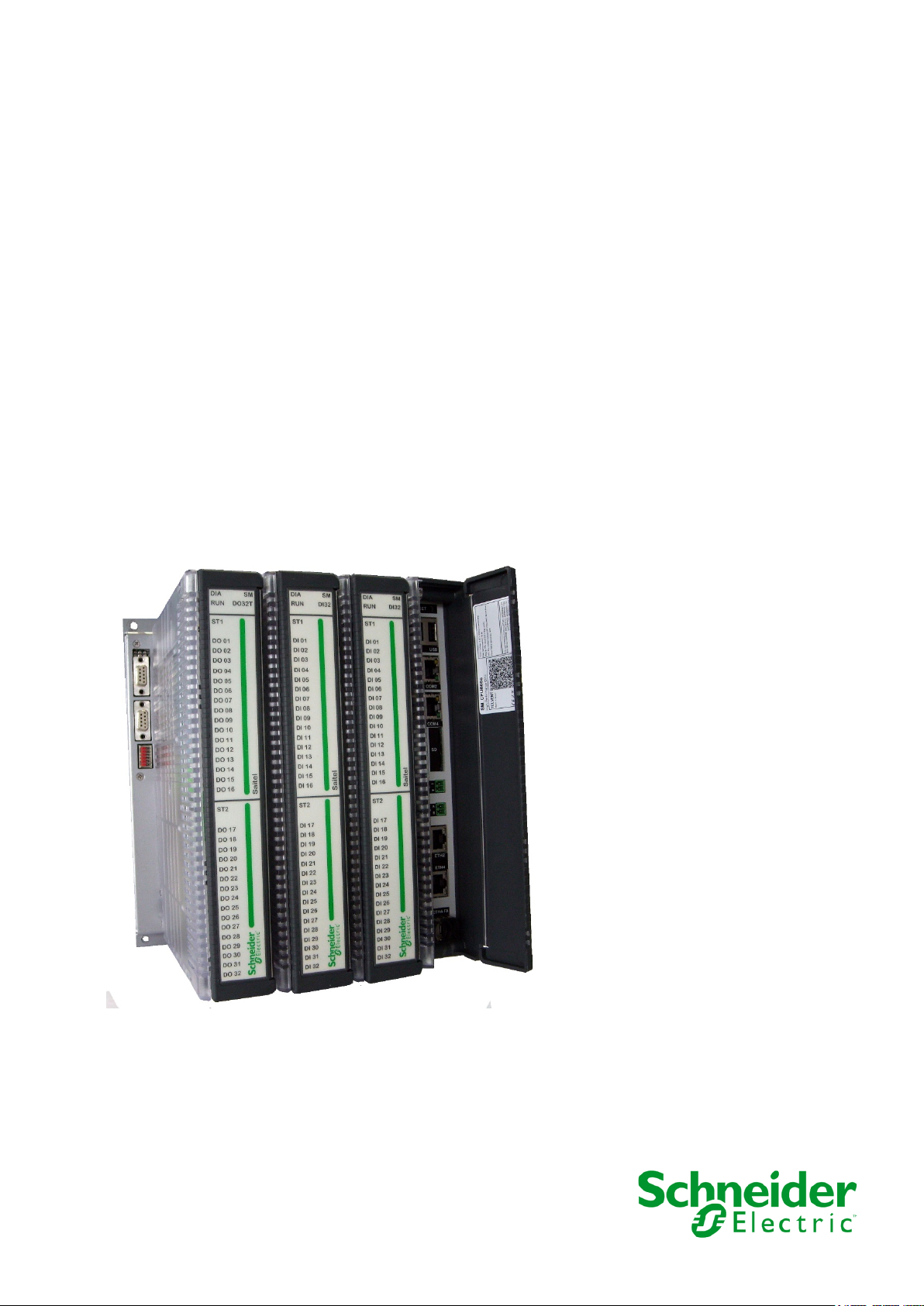
Saitel DP
Backplane & Chassis RTU
User Manual
This manual provides general information about Saitel DP Platform, including
installation, wiring and other useful data for installers and designers.
SE-F700-USR
Publication Date (06/2020)
Read carefully the information contained in this manual before assembly, installation and use of the
equipment.
www.schneider-electric.com
30/06/2020
User Manual – Saitel DP Platform
01
30-06-2020
Initial edition.
Easergy Builder user manual
FTE-S856-MSS
webApp user manual
FTE-S856-WAT
IEC101 user manual
FTE-S854-I1D
IEC104 user manual
FTE-S854-I4D
IEC103 Master user manual
FTE-S854-I3D
Modbus user manual
FTE-S854-MBD
ISaGRAF user manual
FTE-ISD-S854
DNP user manual
FTE-S854-DNP
SOE user manual
FTE-S854-SOE
IEC61850 Ed1 user manual
FTE-S854-IEC61-1
IEC61850 Ed2 user manual
FTE-S854-IEC61-2
SM_CPU866e user manual
SE-M578-USR
SM_DI32 user manual
SE-M583-USR
SM_AI16 user manual
SE-M523-USR
SM_DO32T user manual
SE-M580-USR
SM_DO16R user manual
SE-M586-USR
SM_AI8AO4 user manual
SE-M525-USR
SM_SER user manual
SE-M581-USR
Change Control
Rev Date Description
General Information
The Saitel platform and all its components have been developed in accordance to the requirements
for a quality management system, complying with the ISO 9001:2015 Norm.
Document nº: SE-F700-USR
Revision/Date: 01 / 30-06-2020
File: Saitel DP Platform – User Manual_EN_01.pdf
Retention period:
Reference Documents
Permanent throughout its validation period + 3 years after its
cancellation.
User Manual Document Code
Pag 2

User Manual – Saitel DP Platform
30/06/2020
Software Version in this Manual
The information in this manual is valid for the software versions listed below. This information is
also valid for later versions, although some parameters may change slightly:
Module Description Version
Baseline Software Platform Baseline packaging 11.06.14
Operating System Linux 20.01.24.12.26.34
laqBinC Local Acquisition 10.00.02
thm Synchronization 06.00.02
coreDb coreDb 10.01.11
chan Channels 03.00.20
formBinC Formula 10.00.13
webServer Web server 03.03.02
webApp Web interface 01.00.27
supBinC Supervision 10.01.21
soeBinC Sequence of Events 10.00.07
ST_SER_C0.bin SM_SER firmware 01.00.08
ST_DO32T_C0.bin SM_DO32T firmware 01.00.04
ST_DI32_C0.bin SM_DI32 firmware 01.00.06
ST_AI16_C0.bin SM_AI16 firmware 01.00.03
ST_AI8AO4_C0.bin SM_AI8AO4 firmware 01.00.03
ST_DO16R_C0.bin SM_DO16R firmware 01.00.02
Pag 3

30/06/2020
User Manual – Saitel DP Platform
Content
1 SAFETY & HEALTH .................................................................................................. 5
2 SAITEL DP FAMILY ................................................................................................ 16
3 BASELINE SOFTWARE IN SAITEL DP ................................................................. 45
4 PHYSICAL MOUNTING & INSTALLING ................................................................ 58
5 CONFIGURATION & MAINTENANCE .................................................................... 99
Pag 4

User Manual – Saitel DP Platform
30/06/2020
1 Safety & Health
Pag 5

30/06/2020
User Manual – Saitel DP Platform
Content
1 SAFETY & HEALTH .................................................................................................. 5
1.1 INTRODUCTION ........................................................................................................ 7
1.1.1 I
1.1.2 P
1.2 I
1.3 S
1.4 I
1.5 E
1.5.1 E
1.5.2 F
1.6 H
1.7 T
1.7.1 P
1.7.2 E
1.7.3 S
1.8 T
1.9 P
1.10 D
NFORMATION OF SECURITY .............................................................................. 7
RESENTATION ................................................................................................ 8
NTRODUCTION TO SAFETY ....................................................................................... 8
YMBOLS AND LABELS ON THE EQUIPMENT ............................................................. 9
NSTALLATION, SETUP AND OPERATION ................................................................. 10
ARTHING ............................................................................................................. 11
LECTRICAL SAFETY ...................................................................................... 12
UNCTIONAL EARTH (EMC) ............................................................................ 12
ANDLING ELECTRONIC COMPONENTS .................................................................. 13
ECHNICAL SPECIFICATIONS FOR SAFETY .............................................................. 13
ROTECTIVE ELEMENTS ................................................................................. 13
NVIRONMENTAL CONDITIONS ........................................................................ 14
TORAGE CONDITIONS ................................................................................... 14
ECHNICAL LABEL ................................................................................................. 14
ACKING AND UNPACKING ..................................................................................... 15
ECOMMISSIONING AND DISPOSAL ......................................................................... 15
Pag 6
User Manual – Saitel DP Platform
30/06/2020
DANGER indicates a hazardous situation which, if not avoided, will result in death or serious
WARNING
WARNING indicates a hazardous situation which, if not avoided, could result in death or
NOTICE
NOTICE is used to address practices not related to physical injury. The safety alert symbol shall
WARNING
If this equipment is used in a different form from the recommended one by Schneider Electric,
the protection assured for the equipment could be compromised .
1.1 Introduction
1.1.1 Information of Security
Important information
The illustrations shown in this manual are intended for exemplary purposes. As there are variables
and requirements which depend on each particular installation, Schneider Electric will not be held
responsible for the misuse of the equipment based on the examples herein published
Read these instructions carefully and look at the equipment to become familiar with the device
before trying to install, operate, service or maintain it. In this manual you can find different types of
messages associated with situations that have different level of risk for people and / or for the
equipment.
injury.
This symbol indicates "DANGER" or "WARNING". This symbol informs of an
electrical risk that will cause personal injuries if the instructions are not followed.
This symbol is associated to a safety alert. It is used to warn of possible personal
injury hazards. The user must follow all instructions or messages associated to this
symbol to avoid possible injuries.
DANGER
serious injury.
not be used with this signal word.
Restricted Liability
Electrical equipment should be serviced and maintained only by qualified personnel. All person
who can contact the equipment must be informed and must read the chapter “Safety & Health” of
this manual.
No responsibility is assumed by Schneider Electric for any consequences arising out of the use of
this manual. This document is not intended as an instruction manual for untrained persons.
Pag 7
30/06/2020
User Manual – Saitel DP Platform
Before carrying out any work on the equipment the user should be familiar with the
WARNING
Before working with the terminal of connection, the device must be turned off and disconnected
To Keep in Mind
Electrical equipment should be installed, operated, serviced, and maintained only by qualified
personnel. No responsibility is assumed by Schneider Electric for any consequences arising out of
the use of this material.
A qualified person is who fulfill with requirements in 1.2 .
1.1.2 Presentation
This manual provides information for a safe handling, commissioning and testing. This Safety
chapter also includes descriptions of the labels on the equipment.
Documentation for equipment ordered from Schneider Electric is dispatched separately from
manufactured goods and may not be received at the same time. Therefore, this guide is provided
to ensure that printed information which may be present on the equipment is fully understood by
the recipient.
The technical data in this safety guide is typical only, see the technical data section of the user
manual for specific details of a particular equipment.
contents of this Safety chapter and the ratings on the equipment’s rating label.
THE SAFETY SECTION MUST BE READ BEFORE STARTING ANY WORK ON
THE EQUIPMENT.
1.2 Introduction to Safety
The information in this section is intended to get that equipment is properly installed and handled in
order to maintain it in safety conditions. It is assumed that everyone who will be associated with the
equipment will be familiar with the contents of that Safety section.
When electrical equipment is in operation, dangerous voltages will be present in certain parts of the
equipment. Failure to observe warning notices, an incorrect or improper use may endanger
personnel and equipment and also cause personal injury or physical damage.
of the feeding.
Proper and safe operation of the equipment depends on appropriate shipping and handling, proper
storage, installation and commissioning, and on careful operation, maintenance and servicing. For
this reason, only qualified operator may work on or operate the equipment.
Qualified operator are individuals who:
• Have read and understood the information on the device and its user manual.
• Are familiar with the installation, commissioning, and operation of the equipment and of the
system to which it is being connected.
• Are able to safely perform switching operations in accordance with accepted safety engineering
practices and are authorized to energize and de-energize equipment and to isolate, ground,
and label it.
Pag 8
User Manual – Saitel DP Platform
30/06/2020
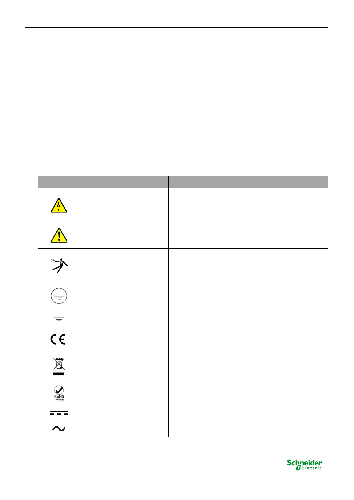
Symbol
Associated Text
Description
International Electrotechnical Commission (IEC) symbol
Symbol associated with a risk alert. The user must read
American National Standards Institute (ANSI) symbol
Associated symbol to the protective ground connection.
Associated symbol to the functional ground connection.
This symbol indicates that the equipment has been
This symbol indicates that, at the end of its life, this
The equipment has been designed and manufactured
Direct Voltage
Symbol of direct voltage (VDC).
Alternate Voltage
Symbol of alternate voltage (VAC).
• Are trained in the care and use of safety apparatus in accordance with safety engineering
practices.
• Are trained in emergency procedures (first aid).
It is necessary to consider that the documentation of the device collects the instructions for its
installation, set up and operation. However, the manuals could not cover all the possible
circumstances neither include specific information on all the details.
In case of questions or specific problems, contact with his office of sales Schneider Electric or with
the center of attention to the customer and request the necessary information.
1.3 Symbols and Labels on the Equipment
Before the equipment is installed or commissioned, the user must understand the following
symbols, which may be used on the equipment or referred to in the user documentation.
Table 1 – Symbols
associated to a DANGER or WARNING message
Possibility of electric chock
indicating that there is an electrical risk. Failure to follow
these instructions could cause damage to people or
death.
Caution, read the manual.
Possibility of electric chock
Protective earth connection
Functional earth connection
CE Mark
Electronic device. Special
instructions must be follow
for discard it.
Compliant with RoHS.
the manual before handling the equipment.
associated to a DANGER or WARNING message
indicating that there is an electrical risk. Failure to follow
these instructions could cause damage to people or
death.
See paragraph 1.5.1 in this manual.
See paragraph 1.5.2 in this manual.
developed in compliance with all applicable European
Directives.
module must be discarded according to the WEEE
Directive (Waste Electrical and Electronic Equipment).
according to RoHS Directive (Restriction of Hazardous
Substances).
Pag 9
30/06/2020
User Manual – Saitel DP Platform
DANGER
Devices that handle dangerous tensions are marked with a sticker on the front label (size: 12,5
WARNING
If this type of cabinet isn't available, a barrier must be installed in order to avoid an accidental
1.4 Installation, Setup and Operation
The user is responsible for reading and following the device’s operating and installation instructions
before attempting to commission or maintain it. Failure to follow these instructions can affect device
operation and constitute a hazard for people and property.
There are several acquisition blocks in Saitel DP that use high voltages (> 50 V). The user is
responsible to check that the characteristics of each equipment are adapted and convenient for his
installation.
Not following these instructions can be dangerous for the people and the equipment.
mm). This label must be visible when the module’s door is open, and the field connectors are
accessible.
The following products handle dangerous tensions:
• SM_PS40: Power supply module (P/N: M5084x000x and M5085x000x).
• SM_DI32: Digital inputs module (P/N: M583x0000x).
• SM_DO32T and SM_DO16R: These modules do not handle high voltages, they will not be
marked at the factory. These modules must be marked with an electric risk label when some
equipment that manage voltage higher than 50 V are connected to digital outputs.
It is recommended to install the RTU inside a cabinet with a key. This cabinet only should be
opened by a qualified person.
contact with these dangerous elements. This barrier only should can be removed using a
special tool.
If the barrier has to be removed in order to access to equipment, personnel responsible for the
task must be sure that the barrier is installed again when the task is finished.
While the RTU is accessible for a user, all people must follow all instructions to prevent
electrical risk or discharges.
Not following these instructions can give like result that the device do not work properly
or even can damage to the people or devices.
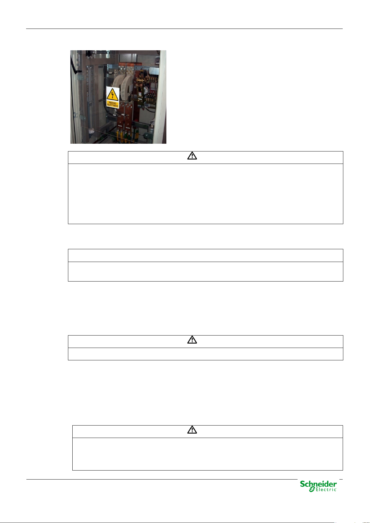
An electrical risk symbol with enough size must be included on the cabinet’s door or
on the barrier.
The following image shows an example:
Pag 10
User Manual – Saitel DP Platform
30/06/2020
WARNING
If the barrier has to be removed in order to access to equipment, personnel responsible for the
NOTICE
The cabinet must remain closed with key or the protection barrier installed after the installation is
WARNING
Don’t use liquid products of cleanliness due to the presence of active parts.
WARNING
Figure 1 – Barrier of protection for elements with dangerous voltages.
task must be sure that the barrier is installed again when the task is finished.
While the RTU is accessible for a user, all people must follow all instructions to prevent electrical
risk or discharges.
Not following these instructions can give like result that the device do not work properly or
even can damage to the people or devices.
Terminals will not be accessible to the user directly once it has made the installation of the
equipment.
finished.
The cabinet or installation must have a general switch placed just in the cable entry of the
installation (see paragraph 1.7.1 )
For the cleaning of the equipment, it is recommended to remove the power and to use only a dry
cloth by the surface when it detects excessive presence of dust or any element deposited on the
surface.
Because of the variety of uses of the product, the managers of the application and use of this
controller device will have to take the measures to ensure the fulfillment of all the requests of
security and provision of each application. The requests do reference to the applicable laws,
regulations, codes and standard.
1.5 Earthing
Before energizer the device, it has to be placed to earth properly such as it indicates in this
section. When installing the device, ground is the first thing that should be connected and the
last one that should be disconnected.
Pag 11
30/06/2020
User Manual – Saitel DP Platform
DANGER
Hazardous voltages can cause shock, burns or death. Disconnect and lockout all power
WARNING
According to the electrical safety standards:
Saitel can need put to earth for two distinct needs:
• For purposes of electrical safety (Protective Earth, PE).
• Improve the behavior in Electromagnetic Compatibility (EMC) and derive perturbations to earth
(functional Earth).
1.5.1 Electrical Safety
Only qualified personnel, with knowledge about hazards associate with electrical equipment is
allowed to install Saitel DP. In general, the installation will be following IEC 61010-1
recommendations in order to be compliant with this norm.
When Saitel DP is mounted on back-panel, the metallic enclosure of the backplane
must be connected to the ground of the cabinet or installation according to the norm
IEC 61010-1. When Saitel DP is mounted on a chassis, this chassis must be
connected to the ground of the installation.
Saitel DP modules have a plastic enclosure offering protection for isolation faults. Earthing
sources before servicing and to dismount modules.
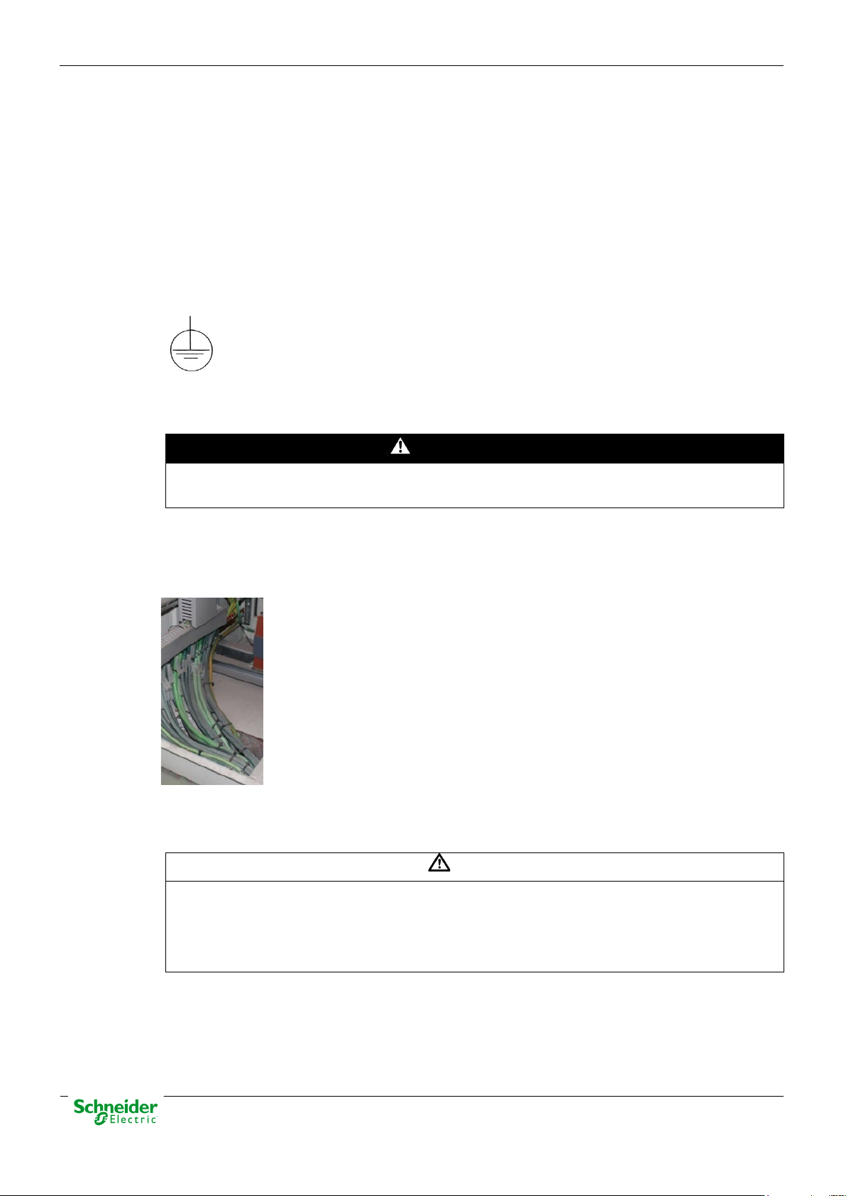
A dedicated connection with green/yellow wire should be used to have electric continuity to the
installation protective earth. Use a wire with adequate section according to IEC 61010.
Figure 2 - Example of yellow/green cable for earthing.
The design and installation of the cabinet is responsible for compliance with all the existing
international and national electrical codes concerning protective grounding of any device.
• The screw for ground must be exclusive for this use.
• The power voltage must be supplied by a power supply that offers double or reinforced
insulation against dangerous voltages.
1.5.2 Functional Earth (EMC)
A rear connector available in each module allows the bus connection and it offers protection in
case of electric derive. The EMC grounding is implemented via three pins of this connector.
Pag 12
User Manual – Saitel DP Platform
30/06/2020
WARNING
Never connect modules on the backplanes if the power supply hasn’t been disconnected of all
WARNING
The enclosure ONLY should be removed when is strictly necessary, because this action has a
WARNING
The connection / disconnection switch must be installed in a fixed element (for example the wall
circuits with high voltages.
The only modules with a ground connection are the power supplies (SM_PS and SM_PS40). Both
must be connected to the ground of the cabinet.
1.6 Handling Electronic Components
Saitel is susceptible to receive electrostatic discharges during the handling. It is necessary to take
the usual measures to minimize this risk, since serious damage to the equipment can be caused,
which may not be detected immediately but which may affect the reliability of the product.
risk for the equipment:
• Before removing the enclosure, the operator must be equipotential with the equipment.
• Avoid touching the electronic. The board must be always manipulated for the edges.
• If the equipment has to be passed between two persons, both must be equipotential.
• Put the module always on an antistatic surface or on a surface equipotential with you.
• During the storage and transport, the module will remain in the packaging.
Not following these instructions can give like result that the equipment do not work
properly or even can damage the people or equipment.
1.7 Technical Specifications for Safety
1.7.1 Protective Elements
The cabinet's engineering and installation must include a general automatic switch next to the
cables' input in the cabinet; once the door is opened, high voltages must be interrupted inside. This
switch must be located at a place which is not accessible by a third person while the operator is
using the boards in the cabinet.
Moreover, the installation will incorporate a circuit breaker of 5A next to the cabinet protecting it
from possible overcurrent in the power supply.
Both switches will be labeled with the symbol O as "Off" and I as “On”.
of the cabinet) and it mustn’t break any earthing wire.
Pag 13
30/06/2020
User Manual – Saitel DP Platform
WARNING
This equipment has been designed ONLY for indoor use.
1.7.2 Environmental Conditions
The protection degree of the device is IP20.
It is designed only for indoor use. If necessary for use in an outdoor environment, it must be
mounted in a specific cabinet providing an IP54 degree of protection (typical and minimum for
ATEX conditions), that is, protected against dust and water splashes.
The electronic cards of the modules will be able to be tropicalized or no according to the option of
setting chosen. The tropicalized used is the AVR80, of the company ABchimie. It can consult all the
technical information of this type of finishing in http://www.abchimie.com/
Other data to take into account about the environmental are:
• Altitude until 2000 m.
• Operation temperature range: Between -40 ºC and 70 ºC. (IEC 60068-2-1 and IEC 60068-2-2).
• Maximum relative humidity of 95%. (IEC 60068-2-30)
• Degree of pollution II. (IEC 60255-5)
.
• Overvoltage transitory until levels of Category III. (IEC 60255-5)
1.7.3 Storage Conditions
The continuous exhibition to some high levels of humidity during the storage can cause damages
to the electronic components and reduce the useful life of the device.
It is recommended that, in the enclosure of storage, the relative humidity do not exceed 50%.
Before the installation of an electrical equipment, it is recommended to leave the necessary time for
the acclimatization of the environmental temperature.
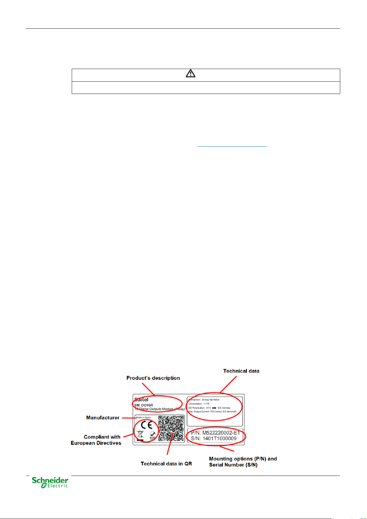
1.8 Technical Label
Each Saitel product includes a technical label with the following information:
Figure 3 - Technical label.
Pag 14
User Manual – Saitel DP Platform
30/06/2020
NOTICE
On the “Technical data” zone, you can see relevant information about the input and output
NOTICE
Our products leave our factory in closed, sealed original packaging. If at receipt of the delivery
WARNING
Only a qualified person should change the battery when is necessary, and the same model of
voltage in the module. Any voltage greater than 50 V must be consider as a high voltage.
1.9 Packing and Unpacking
All Saitel modules are packaged separately in their own carton box and shipped inside outer
packaging. Use special care when unpacking the device. Don’t use force.
the transport packaging is open or the seal is broken, the confidentiality and authenticity of the
information contained in the products cannot be ensured.
The design revision and manufacturing options can be determined using the P/N included in the
packaging label on packaging.
After unpacking the device, inspect it visually to be sure it is in proper mechanical condition.
If the product needs to be shipped, the original packaging must be used, including foams and the
carton box. If the original packaging is no longer available, make sure that the packaging used is
according to ISO 2248 specifications for a drop height 1 m.
1.10 Decommissioning and Disposal
Saitel products are marked with this symbol, it means that, at the end of its life cycle,
you mustn't dispose the product together with habitual residues. To avoid the
possible damage to the environment or to the human health that represents the
uncontrolled elimination of residues, please, separate the battery (if there is one) of
the other elements, and each one must be recycled according to the local regulation.
SM_CPU866e module includes a Lithium battery NOT rechargeable. More information about the
model in the technical data table included in the SM_CPU866e user manual.
battery must be used. More information in the technical specifications table at the end of each
user manual.
Pag 15

30/06/2020
User Manual – Saitel DP Platform
2 Saitel DP Family
Pag 16

User Manual – Saitel DP Platform
30/06/2020
Content
2 SAITEL DP FAMILY ................................................................................................ 16
2.1 FIRST APPROACH .................................................................................................. 18
2.2 S
2.3 T
2.4 P
2.5 R
2.6 RTU
AITEL DP MODULES ............................................................................................ 19
2.2.1 G
2.2.2 C
2.2.3 LED
2.3.1 CPU
2.3.2 C
2.3.3 I/O
2.3.4 O
2.4.1 S
2.4.2 RTU
2.5.1 P
2.5.2 CPU
2.5.3 A
2.5.4 S
2.5.5 R
ENERAL FEATURES ...................................................................................... 19
ONFIGURATION SWITCHES ............................................................................ 19
INDICATORS ........................................................................................... 20
YPES OF MODULES .............................................................................................. 21
MODULES .............................................................................................. 21
OMMUNICATION MODULES ............................................................................ 21
MODULES ................................................................................................. 22
THER MODULES ........................................................................................... 24
ROFIBUS & SAITEL DP ......................................................................................... 26
YSTEM BUSES .............................................................................................. 26
BASIC FUNCTIONS .................................................................................. 28
EDUNDANT CONFIGURATIONS IN SAITEL DP ......................................................... 30
OWER SUPPLY REDUNDANCY ....................................................................... 30
REDUNDANCY ........................................................................................ 34
CQUISITION BUS REDUNDANCY ..................................................................... 39
YSTEM’S DUALITY ......................................................................................... 40
ECOMMENDATIONS ....................................................................................... 41
EXPANSION ................................................................................................... 42
Pag 17

30/06/2020
User Manual – Saitel DP Platform
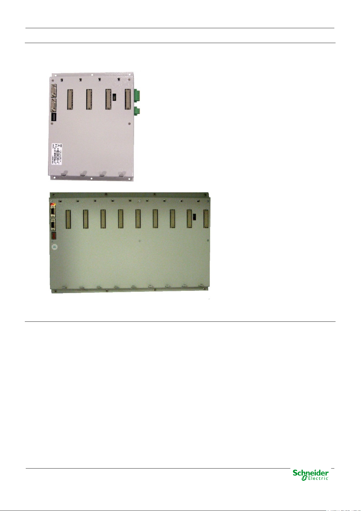
2.1 First Approach
The Saitel DP platform is a complete set of devices provided by Schneider Electric for real-time
control applications and power line automation. It is a high-technology platform which gives a
solution to the business areas of Schneider Electric.
Figure 4 – Saitel DP in chassis and backplane.
Saitel DP’s design has been optimized to meet the most demanding requirements of multiple
sectors:
• Cost-efficiency, minimum downtime, and compliance with electrical safety, electromagnetic
compatibility and environmental standards.
• Safety and reliability requirements for power, gas, water, residual water supply, etc.
• Centralized monitoring and control of geographically-distributed systems which support
hierarchical data acquisition and redundant networks.
• Local monitoring and control with data sharing capabilities of plant-distributed devices.
• Quick troubleshooting by means of programmable automation execution.
• One of the most remarkable features of Saitel DP is its modular design. All I/O, CPU, power
supply and communication modules have an identical format, sharing the same enclosure.
Figure 5 – Saitel DP architecture.
Pag 18
User Manual – Saitel DP Platform
30/06/2020
Never open the module’s enclosure. Never install an electronic board without the plastic
2.2 Saitel DP Modules
The Saitel DP electronic modules have been designed to operate in aggressive industrial
environments, complying with the highest standards, such as Electromagnetic compatibility (EMC).
The low-consumption design allows modules to operate without a forced ventilation system, which
creates a wide range of possible applications.
2.2.1 General Features
The next figure shows an example of a Saitel DP module:
Figure 6 – Saitel DP module
The modules have a plastic enclosure that especially it is designed to facilitate the insertion and the
wiring of the modules. The level of protection provided by the enclosure is IP20connections and
disconnections.
enclosure.
Internally, all modules are electrically connected to the backplane using a 48-pin connector on the
rear side. In relation to the connection with external devices, all the elements required for the
module’s operation and maintenance tasks are located on the front side.
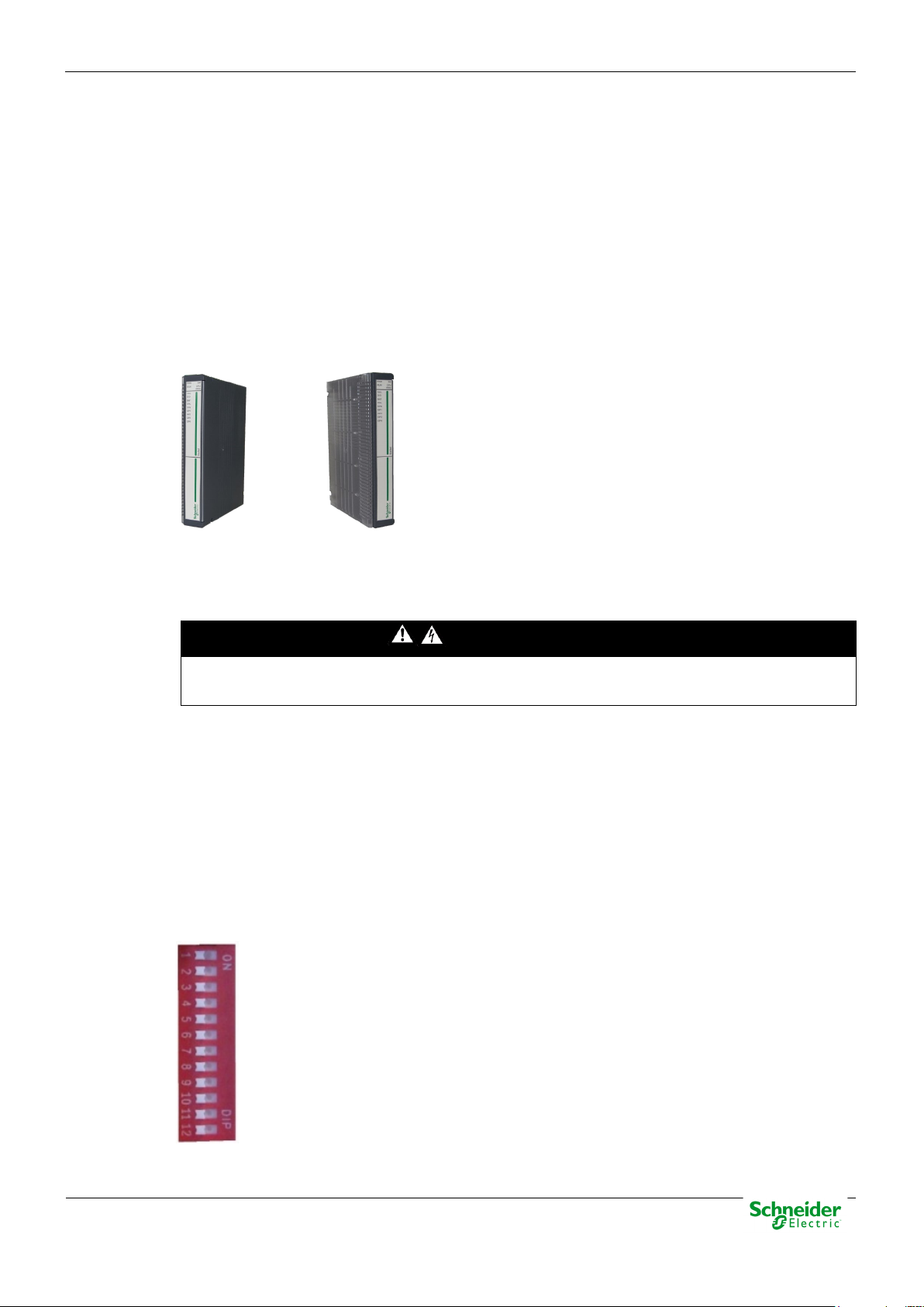
2.2.2 Configuration Switches
The modules integrate a 12-position switch on the rear side. The function of these switches
depends on the module type, but in general, it is used to set the addresses and communication
rate.
Figure 7 – Module’s configuration switches
DANGER
Pag 19
30/06/2020
User Manual – Saitel DP Platform
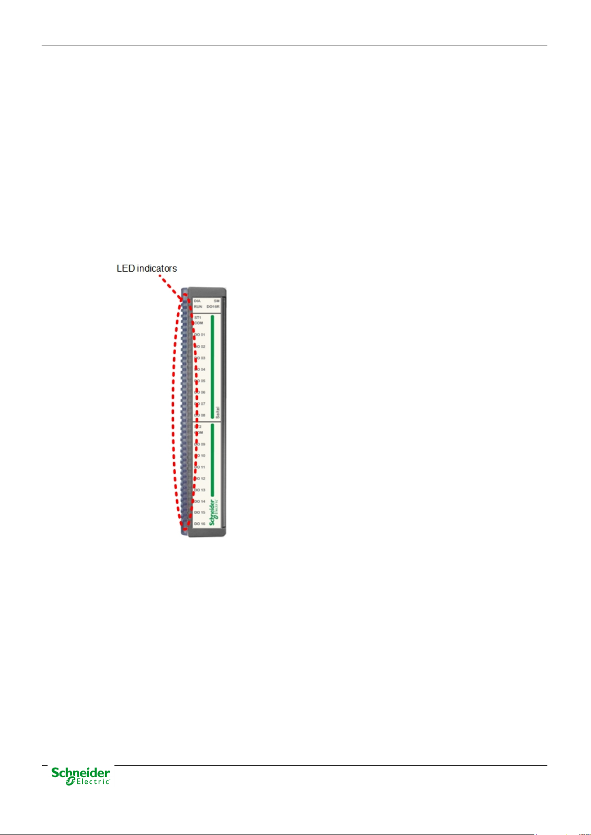
2.2.3 LED Indicators
The Saitel DP modules include some visible LEDs (light emitting diodes) on the front side. All
acquisition modules have common LEDs, and the rest are specific for each module, which are
detailed in the corresponding user manual.
The front panel of each acquisition module has a red indicator DIA and a green indicator RUN. The
module performs a self-check during the start-up process. When successful, the red indicator is
switched off and the green indicator displays the module’s configuration status.
If any problem is detected, the red indicator DIA is switched off. The meaning of these LEDs
depends on the module type and it is explained in the user manual for each module.
This information will only be valid if the module is completely configured and operational.
Figure 8 – LED indicators
Consult the module’s user manual for more information regarding interfaces, configuration switches
and led indicators.
Pag 20

User Manual – Saitel DP Platform
30/06/2020
2.3 Types of Modules
2.3.1 CPU Modules
SM_CPU866e – High-Performance CPU
• OS: Linux.
• Web tool: webApp.
• Ethernet ports: 4 (copper or fiber optic).
• USB port and SD card.
• Synchronization: GPS / SNTP / IRIG-B / Protocol.
• Serial communications: 4 ports (RS-232 / RS-485).
• Watchdog output.
• Command console tool: RJ-45 port.
• Cybersecurity
2.3.2 Communication Modules
SM_SER – Communication module
• 8 serial ports.
• RJ-45
• Synchronous and asynchronous communications
• Synchronization from SM_CPU866e.
• RS-232 / RS-485 / RS-422
Pag 21
30/06/2020
User Manual – Saitel DP Platform
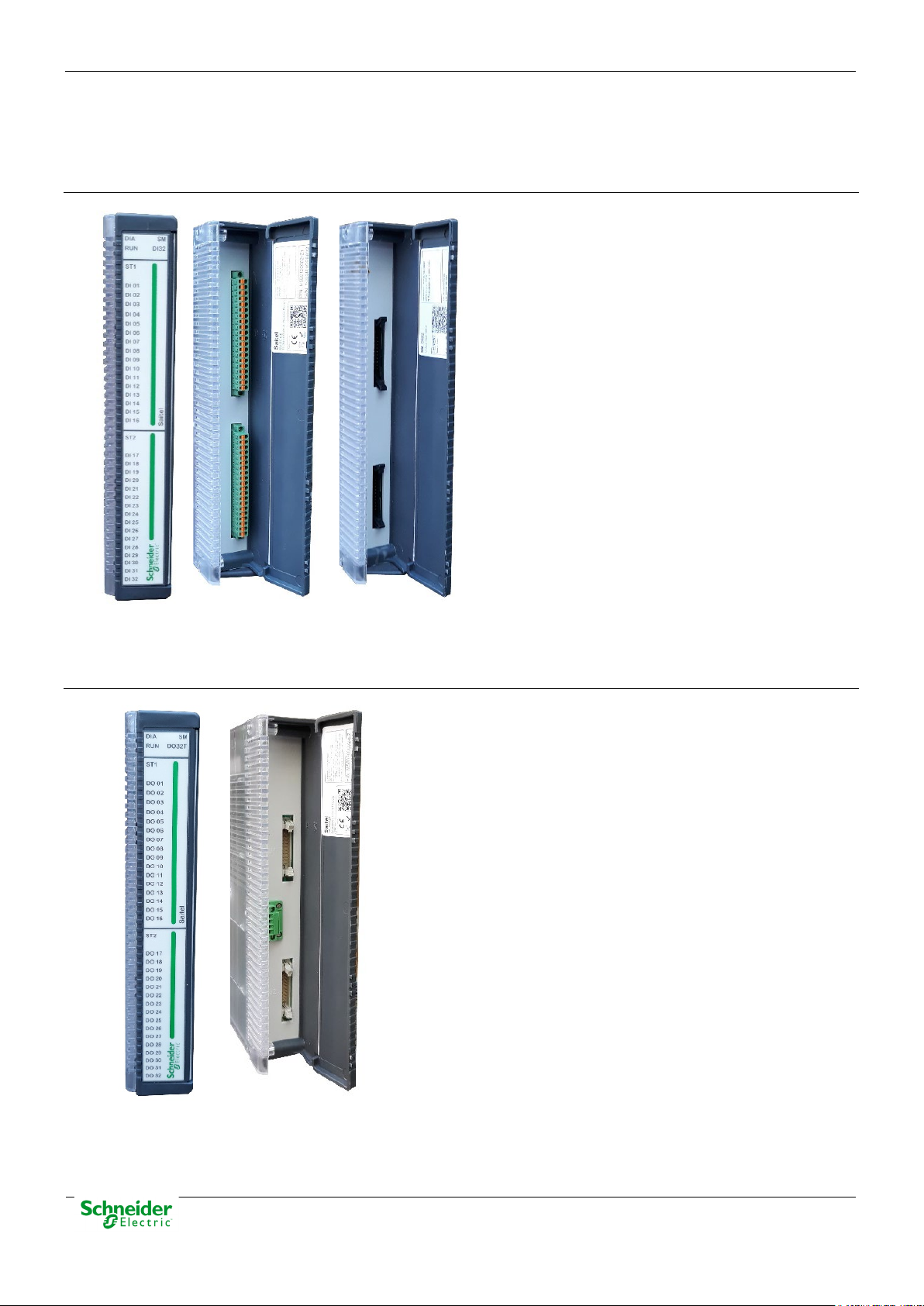
2.3.3 I/O Modules
The following I/O modules are available:
SM_DI32 – Digital Inputs
• 32 digital inputs (single/double/slow
counter)
• Two removable connectors.
• Field connection: Terminal blocks or
Flat Ribbon
• Auto-range for DI polarization. Available
ranges:
o 12 - 24 VDC
48 - 60 V
o
o 110 - 125 V
o
220 V
DC
DC
DC
SM_DO32T – Digital Outputs to Transistor
• 32 digital outputs to transistor.
• Two removable connectors for signals.
• One removable connector for polarization (only for field
connection using flat ribbon).
• Field connection: Terminal blocks or Flat Ribbon
• Outputs type: Normally Open or Normally Closed contacts
(configurable in the external terminal lock).
• DO polarization (auto-detected). Available levels:
o 12 V
o 24 V
o 48 V
DC
DC
DC
Pag 22
User Manual – Saitel DP Platform
30/06/2020
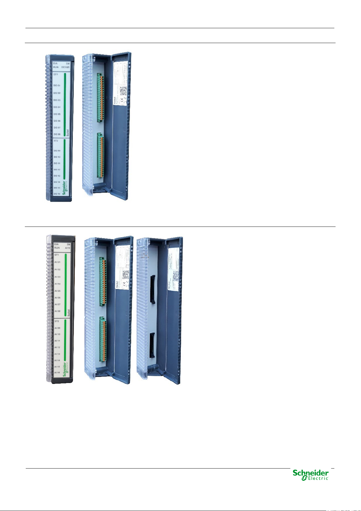
SM_DO16R – Digital Outputs to Relay
• 16 digital outputs to relay.
• Two removable connectors for signals.
• Only terminal block is available for field connection.
• Outputs type: SPST or Normally Open contacts.
• Two polarization levels are available for DO. Depending on
the ordering options, polarization input will be:
o B2: 24 VDC
o B3: 48 V
DC
SM_AI16 – Analog Inputs
• 16 analog inputs
o Voltage
o Current (external resistor is
required).
• Two removable connectors for signals.
• Field connection: Terminal blocks or
Flat Ribbon
Pag 23
30/06/2020
User Manual – Saitel DP Platform
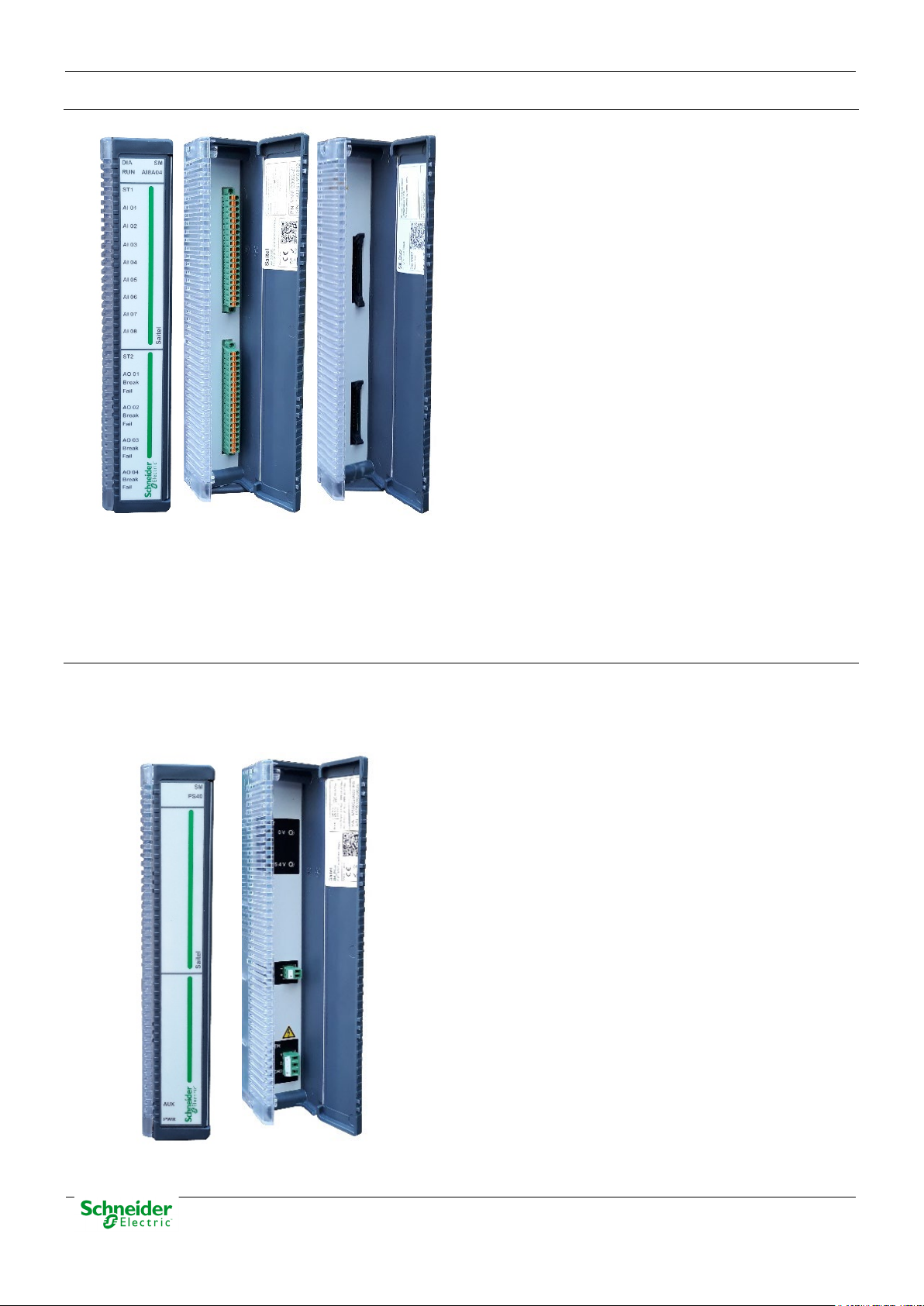
SM_AI8AO4 – Analog Inputs
• 8 analog inputs
o Voltage
o Current (external resistor is
required).
• 4 analog outputs
o Voltage (external resistor is
required)
o Current multirange.
• Two removable connectors for signals.
• Field connection: Terminal blocks or
Flat Ribbon
2.3.4 Other Modules
Other modules are available in Saitel DP: power supply, backplanes, chassis and BP2F.
SM_PS40 – Power Supply
Saitel DP includes a power supply module which has been specifically designed to power the
electronic components on the backplanes and provide the required polarization voltage to the
acquisition modules. Saitel DP backplanes also support external power supplies.
• Power input depending on the P/N:
o A2: 24 V
o A3: 48 V
o A4: 110 / 125 V
o A5: 110 / 230 V
• Power output: 5.4 V
• Auxiliary power output: 24 V
.
DC
.
DC
.
DC
.
DC/AC
to the backplane.
DC
DC
, available or not depending
on the P/N.
Pag 24
User Manual – Saitel DP Platform
30/06/2020
SM_BPX – 9-slot or 4-slot Backplane
Saitel DP modules must be mounted on an electronic board named “backplane”. SM_BPX mounts
this electronic board in a metallic enclosure which can be installed in a panel or flat wall.
• Power input: 5.4 V
DC
(if a
SM_PS40 module is not used)
• Two connectors for expansion
and one connector for external
power supply.
• Configuration switches for
Profibus and synchronization
expansion.
• Led indicators for bus
communications and power.
• The number of slots depends of
the P/N:
o A4: 4-slot
o A9: 9-slot
SM_CHX – 19-inch Chassis
The electronic board backplane can be mounted in a 19-inch chassis:
• Power input: 5.4 V
(if a SM_PS40
DC
module is not used)
• Two connectors for expansion and one
connector for external power supply.
• Configuration switches for Profibus and
synchronization expansion.
• Led indicators for bus communications
and power.
• The number of slots depends of the P/N:
o A4: 8-slot (2 x 4-slot)
o A9: 9-slot
Pag 25
30/06/2020
User Manual – Saitel DP Platform
NOTICE
It is important to note that, both the first chassis and the last chassis or backplane, must be
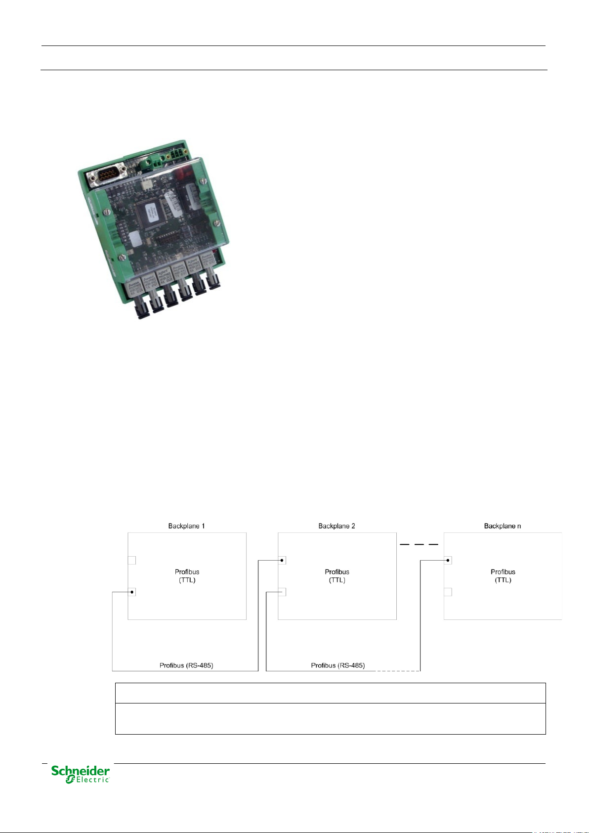
BP2F – Auxiliary Module for Expansion
BP2F (Backplane to Fiber) is a RS-485 to fiber optics converter, specifically designed by Schneider
Electric for the communication between Saitel DP backplanes. This device allows the creation of a
fiber optics bus for communications between backplanes physically far away avoiding distance and
electromagnetic problems.
• Type of fiber optic depending on the P/N:
o A1: 820 nm.
o A2: 650 nm.
• Power input: 5.4 V
DC
.
2.4 Profibus & Saitel DP
2.4.1 System Buses
Each backplane includes a multifunctional bus (Profibus TTL) that covers the power and
intercommunication requirements. This bus is designed to be tolerant to power and communication
failures. Additionally, a Profibus RS-485 is included to support backplane expansion.
The figure below shows schematically the situation of both buses in the system:
Figure 9 – Profibus TTL and Profibus RS-485
configured as bus terminations. See section 4.2 Backplane Modules in this manual.
Pag 26
User Manual – Saitel DP Platform
30/06/2020
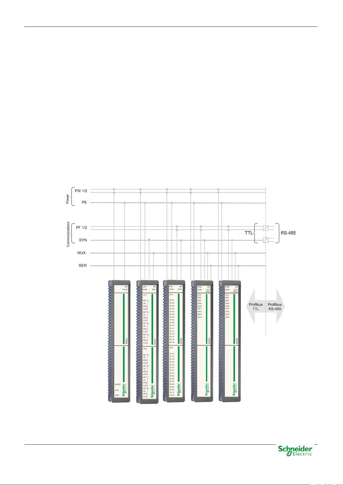
These buses integrate the following bus lines:
• Profibus TTL:
o PE - Protection ground.
o PW1/2 – Power bus (primary and redundant).
o PF1/2 (TTL) - Primary and redundant Profibus TTL buses.
o MUX - Serial data bus for communications with the SM_SER module.
o SYN (TTL) - Bus for synchronization for the modules. (Pulse Per Second or PPS).
o SER - Serial bus for synchronization between redundant CPU modules.
• Profibus RS-485:
o PF1/2 (485) - Primary and redundant Profibus RS-485 buses.
o SYN (485) - Bus RS-485 for synchronization for the modules. (PPS).
The figure below shows the buses available in the backplane:
Figure 10 – Buses in a backplane.
Pag 27
30/06/2020
User Manual – Saitel DP Platform
NOTICE
The primary source is used to synchronize the RTU, if available. Otherwise, the secondary
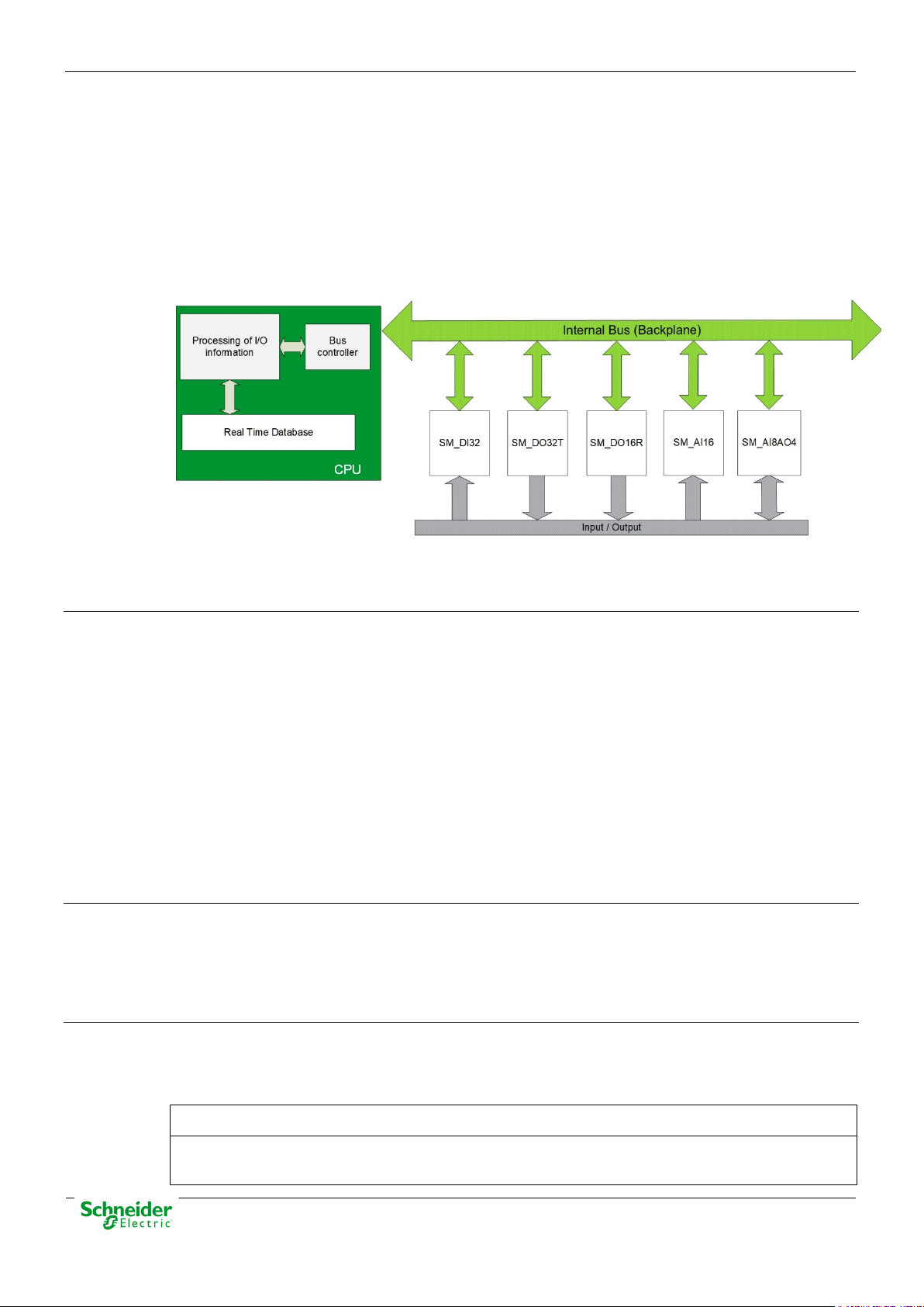
2.4.2 RTU Basic Functions
The control unit (CPU) performs the control functions for the complete system, centralizes the
information acquired by other modules, and executes the programmable logic control,
communication protocols and user-specific applications.
The communication with I/O modules is established by an internal high-speed bus that makes the
system highly reliable even in noisy environments. This bus is implemented in the backplane
Figure 11 – Communication between the CPU and I/O modules.
The CPU module controls and manages the following functions:
Bus Controller
The Baseline software installed in the CPU controls the operation of both, CPU and I/O modules
connected to the backplane.
This control includes:
• Operation mode monitoring. It performs functions as hardware and software Watchdog control,
• Interface with the operator through the console, webApp (for supervision and maintenance)
• Firmware upgrade by SFTP or webApp (using an Ethernet port) or USB 2.0 port.
RTU Configuration
The CPU maintains and manages the information that supports the real-time database, coreDb. In
this database, the I/O signals are related to the communication protocols signals. The configuration
is based on XML files that are generated with the Easergy Builder tool. These files are generated
on a PC and sent to the CPU via an SFTP connection through Ethernet ports.
the states control of the I/O modules and the CPU and the provision of diagnostic information
about the RTU status through LED indicators and several log files. These files can be
consulted by a user with sufficient privileges through SFTP or webApp.
and Easergy Builder (for configuration).
RTU Synchronization
Up to two different synchronization sources can be configured. In this configuration is included the
priority level for each source, so there will be a primary and a secondary source. If both sources
are active, only the primary source will synchronize the system.
source is used.
Pag 28

User Manual – Saitel DP Platform
30/06/2020
The available synchronization sources are:
• GPS: A GPS connected to a serial port. The time received from the GPS is used to set the
system’s clock and the RTC.
• SNTP: A SNTP source through Ethernet. CPU modules can operate as an SNTP client or as
an SNTP server.
• Protocol: Most control protocols allow synchronizing slave devices.
• Console: The user can set the system's time manually from the console terminal.
• IRIG-B: It’s possible to configure the CPU as a server and/or client. The communication always
will be made with IRIG-B compliant devices.
If the synchronization source is not configured, the console device will always be created by
default. The console operates as the lowest priority when another source is configured.
CPU Communications
Saitel DP supports the following communication protocols with field devices:
• IEC101 master and slave.
• IEC103 master.
• IEC104 master and slave.
• DNP 3.0 master and slave.
• Modbus master and slave.
• IEC61850 client, Edition 1 and 2.
• IEC61850 server, Edition 1 and 2.
I/O Acquisition
The CPU manages the information exchange with the I/O modules. This information is sent from
the acquisition module to the CPU through the bus.
The software in the CPU adds the following features:
• Processing I/O information, which offers an added value to the information from field.
• Accessing the internal bus to exchange information with the I/O modules.
Real-time Database (coreDb)
The core of the Baseline Software Platform is the real-time database or coreDb. It is a real-time
database which stores not only the information acquired from field devices, but also the information
about the status of the CPU modules and I/O modules included in the RTU.
coreDb also relates the acquisition signals to the communication protocol signals. This database is
generated in the CPU by using the configuration information.
The information which is received from field in real time is processed, stored in the coreDb and
then related to the communication protocols signals of the RTU, which function is to transfer that
information to the master device.
Pag 29

30/06/2020
User Manual – Saitel DP Platform
coreDb can also have as a source of information the result of a logic, which can be implemented by
a third-party software such as ISaGRAF® or within the database itself witch an internal device of
the type “Formula”.
Consult more information about this functionality in the Easergy Builder user manual.
Cybersecurity
SM_CPU866e is supplied with a standard security policy, complemented with the definition of an
RBAC model (Role-Based Access Control). This model is defined and managed through a special
tool, CAE (EcoStruxure™ Cybersecurity Admin Expert.
2.5 Redundant Configurations in Saitel DP
Due to the wide range of redundant configurations supported by Baseline Software Platform and
Saitel DP, it is necessary to make a detailed analysis in order to determine the concepts applicable
to functionalities and to set a common terminology.
It should be highlighted that redundancy always intends to increase the level of reliability and
availability of the critical elements within a control system.
Redundant configurations are defined to strengthen the following parts of the control system:
• Power supply: This is the first doubled element in the system, since a power supply fails
would mean a total power-off of the system. Power supply units are also devices which transfer
powers, sometimes extremely high and could cause a significant wear of the components. All
Saitel P modules and most auxiliary elements support a redundant power supply.
• CPU: The SM_CPU866 and SM_CPU866e modules allow defining configurations with CPU
redundancy with a high level of flexibility meeting the specific requirements of any system.
• Acquisition bus: The acquisition bus allows the CPU to acquire data from acquisition
modules. Saitel DP backplanes include a double acquisition bus. The CPU module together
with the acquisition modules implement the functions to make an efficient use of these
redundant communications.
• Communication channels: Several master and slave communication protocols support a
double communication channel, which are switched with certain rules according to the protocol.
• System’s duality: All the system’s components are doubled under this configuration. This is
the typical configuration of data hubs and communication front-ends.
Different types of redundancy can be combined in order to make the system as much robust as
possible with doubled elements..
2.5.1 Power Supply Redundancy
Power supply redundancy consist of the use of multiple power supply units for the same backplane.
Thus, the power supply reliability is much improved.
The SM_BPX and SM_CHX backplane have two different power supply options available:
• Power supply using SM_PS40 units
• Power supply using external power supply units.
In both cases, it is possible to have a simple or redundant configuration.
Pag 30

User Manual – Saitel DP Platform
30/06/2020
WARNING
If two power supplies are connected as primary or secondary power supplies, the electronic
Power Supply Redundancy in SM_BPX
In the redundant configuration, the first SM_PS40 module is connected to the slot 1 in the
backplane and the second SM_PS40 module is connected to the slot 2 in the backplane.
Figure 12 – SM_BPX backplane with two SM_PS40 modules.
If an external power supply module is used to power the backplane, it is connected to the lateral
connector (see connector 5 in Figure 47). The connector pinout is shown in paragraph 0.
The combination of an external power supply unit and a SM_PS40 module is possible providing
they both are not the primary or secondary power supplies.
components may be damaged.
Each power supply must be available to provide the 100% of the required power, regardless if
SM_PS40, an external power supply or a combination of the two options is used. Therefore, there
are four possible redundant configurations
Figure 13 – Two SM_PS40 modules.
Figure 14 – Two external power supplies.
Pag 31

30/06/2020
User Manual – Saitel DP Platform
Figure 15 – One SM_PS40 (primary) and one external PS (secondary).
Figure 16 – One external PS (primary) and one SM_PS40 (secondary).
For any of the configurations described above, the power redundancy is achieves using the
adequate wiring.
Power Supply Redundancy in SM_CHX
The SM_CHX backplane has the same power supply options as the SM_BPX backplane, so the
redundancy configuration is similar.
The difference is that the connectors for external power sources are located at the back of the
circuit board rather than on the side (see connector 3 in Figure 49). The pinout of this connector is
detailed in section 0 of this manual.
There are four possible redundant configurations.
Figure 17 – Two SM_PS40 modules.
Pag 32

User Manual – Saitel DP Platform
30/06/2020
Figure 18 – Two external power supplies.
Figure 19 – One SM_PS40 (primary) and one external PS (secondary).
Figure 20 – One external PS (primary) and one SM_PS40 (secondary).
Pag 33

30/06/2020
User Manual – Saitel DP Platform
NOTICE
Both CPU modules must be installed in consecutive slots in the backplane.
2.5.2 CPU Redundancy
The SM_CPU866e module, together with the backplanes (SM_BPX and SM_CHX), supports the
definition of different redundancy configurations of the CPU.
The redundancy types are defined by:
• Physical site: The two CPU are installed consecutively in the same backplane or in different
backplanes.
• Switching mechanism: The switching can be arbitrated by the MSAC module or managed by
the CPU modules themselves.
• Switching type: Both "cold" and "hot" switching are possible. In the first case, the database of
the STANDBY device is not updated with the ONLINE device’s database, but it only updates
when switching is triggered. In the second case, the STANDBY device is constantly updating
the database with the ONLINE device.
• IP address allocation: Baseline Software Platform allows configuring a number of IP
addresses associated to the ONLINE CPU. These addresses are assigned dynamically to
allow CPU modules in redundant systems to inter-communicate and use the same IP address
after switching.
2.5.2.1 CPU Physical Site
Two CPU Modules in the Same Backplane
This is the simplest redundant configuration as it makes the best use as possible of the features of
the backplanes (SM_BPX and SM_CHX). It is the only configuration which allows the two CPU
modules to share the SM_SER communication modules. It also allows (alike in other
configurations) acquisition modules to be shared.
If there are two CPU modules in the same backplane, the switching mechanism can be controlled
by the MSAC module or be managed by the two CPU. In this case, Both CPU can
intercommunicate through a dedicated high-speed channel included in the backplanes or through a
serial or Ethernet link.
Its main disadvantage is that a malfunction in the CPUs’ backplane, caused by any of the modules,
affects the two CPU similarly. Therefore, there are simple faults which might make the two CPU
fail.
Figure 21 – Two CPU modules in the same backplane.
Pag 34

User Manual – Saitel DP Platform
30/06/2020
NOTICE
No other acquisition module can be installed in the backplanes in which the CPU modules are
Two CPU Modules in Different Backplanes
This configuration requires an additional backplane; moreover, the number of SM_SER
communication modules, which are doubled, cannot communicate with the CPU if they are nor in
the same backplane.
The switching mechanism is controlled by the MSAC module or managed directly by the two CPU
modules. In this case, both CPU can intercommunicate through a serial or Ethernet link.
This configuration prevents a simple failure in the backplane from affecting the system completely.
located, since the CPU will not be able to access the acquisition data of the modules located in
the backplane of the other CPU.
Figure 22 – Two CPUs in different backplanes.
2.5.2.2 Switching Mechanisms
MSAC Module
MSAC (Signaling, Arbitration and Switching Module) can, in redundant CPU configurations,
perform the following functions:
• Using a powerful "hardware" protocol, it detects if a CPU is operational or not. It arbitrates
which of the two CPU is ONLINE or STANDBY.
• If a GPS is used for synchronization, the synchronization signal is broadcasted to the two CPU.
• It links each CPU to a relay output, which is activated if the device is operational (ONLINE or
STANDBY) and deactivated if a FAIL status is detected. This relay output can interrupt the
output polarization, signaling, etc.
The MSAC module includes a set of LEDs to indicate the state of each CPU.
Pag 35

30/06/2020
User Manual – Saitel DP Platform
Figure 23 – Switching using the MSAC module.
The CPU (A or B) reports its status to the MSAC. If it is ONLINE, it generates a pulse train, which is
not generated if it is FAIL. The MSAC reports the other CPU whether it should switch to ONLINE or
not, and if the other CPU is in a FAIL status.
RCAP Protocol
If there is no MSAC module installed, the switching van be performed through the RCAP
(Redundancy Control Asymmetric Protocol) protocol.
In this case, there is a communication channel, which can also be redundant, between the CPU
modules. Using this channel, the CPU modules manage the switching through a Schneider Electric
proprietary protocol (RCAP). The communication channels include:
• Ethernet. Communications are established using an IP address through an Ethernet port.
• Serial. The CPU modules communicate using a serial port in the SM_CPU866e module.
• Communication through the backplane (only available when the two CPU are installed in the
same backplane). The backplane incorporates a dedicated serial channel so that the CPU
modules can communicate.
This switching mechanism is specially recommended when the two control modules are installed in
the same backplane or when they are installed at a short distance.
2.5.2.3 Switching Mode
There are two types of switching: “Cold Data” and “Hot Data”.
Cold Data
Under this mode, there is no communication between the two CPU, and when the switching is
performed, the new ONLINE CPU initializes with a database with default values.
Pag 36

User Manual – Saitel DP Platform
30/06/2020
Figure 24 – Switching status under Cold Data mode.
Hot Data
There are three status defined for each CPU:
• STANDBY: Under this status, the CPU is operational, the defined software modules (coreDb,
synchronization, web server,...) in AutoLoad.cfg, the supervision module and ISaGRAF are
loaded. The other BinControllers are not executed. The CPU does not access to the acquisition
bus, the SM_SER communication bus or generate the PPS. The database is not updated.
• ONLINE: Under this mode, the CPU is operational and all applications are executing. The
protocol BinControllers are executed. The communication is activated through the acquisition
bus and SM_SER communication bus; the PPS is generated.
After the switching, communications and acquisition are resumed, and all parameters use
default values.
• FAIL: Under this status, the CPU is not operational.
By adding a second CPU to a control system, this configuration has the advantage of improving
availability considerably so that maintenance, database modifications and testing tasks can be
carried out over the STANDBY CPU, not comprising the system’s performance.
Under Hot Data mode, there is a high-speed communication channel (Ethernet or backplane)
between the two CPU, which is used to update the STANDBY CPU’s database with the ONLINE
CPU’s database. When a switching is performed, the new ONLINE CPU starts with updated
values. In this operation mode, database IDs must be the identical.
The update is performed by exception; it only sends the values of the points which have changed,
except for the first time when the entire database is updated.
The information which is shared by the two CPU is exclusively related to coreDb points; internal
information about the BinControllers is not shared. This is the reason why, some information may
be lost after a switching. Examples of this type of information are events and commands.
The use of a BinController of the laq type which uses a Profibus protocol sending the status of the
outputs constantly achieves that the values sent as outputs will match the values corresponding to
the actuations performed on the points associated in coreDb.
Pag 37

30/06/2020
User Manual – Saitel DP Platform
NOTICE
Hot Data switching has several peculiarities. We recommend you to contact Saitel Support
For BinControllers using other protocols (101,104, DNP) which send commands by exception, no
command is sent after a switching.
ISaGRAF and supervision BinControllers are executed in the STANDBY CPU. The points with
sources in the supervision BinController are not shared by the two CPU.
Both CPU can initialize in different moments, so there is no guarantee that ISaGRAF sequential
program is under the same status in both CPU. If status synchronization between both programs is
required, it must be implemented in the program itself using ISaGRAF variables mapped to coreDb
signals.
Figure 25 – Switching status under Hot Data mode.
There are three status defined for each CPU:
• STANDBY: Under this status, the CPU is operational, the defined software modules in
AutoLoad.cfg (coreDb, synchronization, web server,...), the supervision module and ISaGRAF
are executed. The other BinControllers are not executed. The CPU does not access to the
acquisition bus, the SM_SER communication bus; the PPS is not generated and dbNET is
disabled. Data related to the point status are received from the other CPU and updated in
coreDb.
• ONLINE: Under this mode, the CPU is operational and all applications and protocol
BinControllers are executing. The communication is activated through the acquisition bus and
communication bus; the PPS is generated.
• FAIL: Under this status, the CPU is not operational.
Service to analyses each particular case.
Pag 38

User Manual – Saitel DP Platform
30/06/2020
NOTICE
The backplanes in Saitel DP family have a jumper (J2) which is required to configure the system
2.5.3 Acquisition Bus Redundancy
The backplanes in Saitel DP include four communication buses for module interconnection.
Figure 26 – Communication buses in the backplane
These four buses are:
• Double Profibus-DP communication bus for the communication between I/O modules and
control module (PF1 and PF2).
• Communication bus for synchronizing acquisition modules (SYN).
• High-speed communication bus for the communication between the control module and
communication modules, SM_SER.
• High-speed communication bus for the communication between the two control modules
installed at the same backplane (CPU).
The acquisition bus redundancy in Saitel DP is achieved by the Profibus DP (RS-485) double bus.
This bus enable distributed acquisition architectures to be defined; it is highly flexible and robust
and can cover distances of up to 1500 meters. The communication rate for these channels is
selectable from 9.6 kbps and 1.5 Mbps.
Profibus redundancy is expandable to other backplanes since the channels: PF1, PF2 and SYN
are outputs in the backplane through the expansion connectors.
with Profibus-DP redundant communications. If the jumper is installed, the Profibus-DP
redundancy is enabled.
Figure 27 – Jumper for Redundancy
Pag 39

30/06/2020
User Manual – Saitel DP Platform
Profibus implementation for Saitel DP has the following features:
• There is only one serial controller for the two Profibus buses.
• Messages both from the master and the slaves are broadcasted through the two buses.
• Both the master and the slaves select the reception bus.
• The redundant bridge must be installed in the backplane in order to be able to select the
listening bus. If uninstalled, the listening bus will always be the bus 1.
• When there is no response in the master (including the attempts), the system switches to the
active listening bus.
• If communication is lost between a slave and the master through the two channels during more
than 8 seconds, this event is detected and the adequate diagnostic led is lit.
• The buses are alternatively monitored every minute. Therefore, both fault detection and
recovery may be delayed one minute.
2.5.4 System’s Duality
The system’s duality is the last option in order to maximize the system’s availability. Duplicity
means that all system's elements are doubled. This is the typical configuration of data hubs and
communication front-ends.
In terms of redundancy, there are two CPU in different backplanes with a specific number of
communication modules associated. Both hot and cold switching, which is arbitrated by the MSAC
module, are possible. Even though generally there is no acquisition, it is possible to have
acquisition modules installed in the CPU's backplanes in this case.
Communication channels are multiplexed by using a logic device.
Figure 28 – Dual system
Pag 40

User Manual – Saitel DP Platform
30/06/2020
+
-
+
-
2.5.5 Recommendations
Following paragraphs provide information about the different types of existing redundancies and
which is the most adequate redundancy for each case. Due to the wide range of redundancy
possibilities available for Saitel 2000DP, these proposals are general and open, so it is possible
that the least recommended options here are the most appropriate for a specific project
2.5.5.1 Power Supply
In non-redundant configurations, the use of an external power supply module is recommended as
the most appropriate option for the backplanes. For the same reasons, it is the recommended
option here.
In this case, two slots are not occupied; they can be used for communication or acquisition
modules. Moreover, since the power supply source is different to the polarization source (if
acquisition is available), one can be down without affecting the other.
The table below summarizes the options in order of preference:
Table 2 – Recommendation for redundant power supplies
Configuration
Two external PS
One SM_PS40 (primary) and one external PS (secondary)
One external PS (primary) y one SM_PS40 (secondary)
Two SM_PS40
2.5.5.2 Control Unit
It should be noted that all options are not possible sometimes, especially due to location
restrictions in the CPU modules, database specifications or other requirements.
This section does not cover the switching modes, since it is case-specific.
Regardless these aspects, the preferences both in terms of the control mechanism of the CPU
modules and the exchange methods for the database are explained in detailed in further sections.
The recommendations below take into consideration not only the reliability but also the
communication rate provided by each option.
Table 3 – Recommendation for redundant CPU modules
Configuration Features
Backplane
The dedicated communication channel integrated in the backplane
for switching is very robust and accessible for the CPU modules
only.
Channel through a
serial port.
Channel through a
Ethernet port.
MSAC
A direct wiring between the configured serial ports should be used,
preferably ports in the CPU module although the SM_SER module
is also possible.
A crossed Ethernet cable must be used, since it allows longer
distances than serial communication to be covered. In this case, a
dedicated channel is not required but very recommended.
This option allows for a single synchronization source for the
entire system.
Pag 41

30/06/2020
User Manual – Saitel DP Platform
NOTICE
Cooper wired are generally recommended for the connection within a cabinet and optic fiber
+
-
Table 4 – Communication options for “Hot Data” CPU modules
Configuration Features
The dedicated communication channel integrated in the backplane
Backplane
Channel through a
Ethernet port.
to transmit the database values is the same as the channel for
switching control.
It is less robust than the existing channel in the backplane, but it is
the only method available to update the database of the stand-by
CPU if it is installed in a different backplane. Whenever possible, it
is recommended to have this channel in a dedicated network.
2.5.5.3 Acquisition Bus (Profibus)
If the specific subsystem consists only on a backplane, a Profibus redundancy (that is, setting the
enabling jumper or not) has no effect. Nevertheless, when communications with the acquisition
must be established outside the backplane, then they must be more secured.
To do so, it is possible to take two channels from the same expansion connector or obtain each
channel for a connector.
When distances are relatively long, copper wires should not be used, but optic fiber instead. In this
case, the recommended converter is BP2F.
wires between different cabinets.
For the particular case of a system with redundant CPU modules in different backplanes, the status
of Profibus communications in the STANDBY (inoperational) CPU can be monitored by the
ONLINE CPU.
To do so, at least one acquisition module is required in the CPU backplanes. The ONLINE CPU will
be able to access to those modules, and the status of the module’s diagnostic signals of the
STANDBY CPU will be the status of the Profibus channel (or channels) of the STANDBY CPU.
Therefore, the status of the Profibus channel in the backplane of the STANDBY CPU will be
provided by the acquisition module.
Following paragraph includes some example of Probifus expansion.
If the bottom CPU is the ONLINE CPU will be able to know that the upper CPU in STANDBY status
has lost the Profibus channel when the I/O module does not respond.
2.6 RTU Expansion
The RTU can be expanded to other backplanes (including only I/O modules) according to the
system requirements. All technical information about RTU expansion is included in chapter
Physical Mounting & Installing.in this manual.
Each backplane must be connected to the following using only one or two DB9 connectors,
depending on the system architecture.
Pag 42

User Manual – Saitel DP Platform
30/06/2020
NOTICE
It is important to consider that the synchronization bus (SYN) only can be expanded using one
cable. You could expand it using the PF1 or PF2 cable, but only one of them. Otherwise the
system could have problems with the synchronization in the acquisition backplanes.
Following figures show some example for single and redundant systems, using copper or fiber
optic:
Figure 29 – Backplane expansion – A main backplane / A single expansion cable
Figure 30 – Backplane expansion – A main backplane / A cable for each profibus
Pag 43

30/06/2020
User Manual – Saitel DP Platform
Figure 31 – Backplane expansion (using copper) – Redundant backplanes / Two expansion cables
Figure 32 – Backplane expansion (using FO) – Redundant backplanes / Two expansion cables
Pag 44

User Manual – Saitel DP Platform
30/06/2020
3 Baseline Software in Saitel DP
Pag 45

30/06/2020
User Manual – Saitel DP Platform
Contents
3 BASELINE SOFTWARE IN SAITEL DP ................................................................. 45
3.1 GENERAL DESCRIPTION ......................................................................................... 47
3.2 M
3.3 S
3.4 S
3.5 L
3.6 T
AIN ELEMENTS .................................................................................................... 49
3.2.1
3.2.2 D
3.2.3 U
3.2.4 C
3.6.1 I
3.6.2 D
3.6.3 D
3.6.4 A
3.6.5 A
COREDB – REAL TIME DATABASE (RTDB) ...................................................... 49
EVICES ........................................................................................................ 50
SER INTERFACES ......................................................................................... 50
YBERSECURITY ............................................................................................ 50
OFTWARE TOOLS ................................................................................................. 50
OFTWARE COMPATIBILITY .................................................................................... 51
OCAL ACQUISITION .............................................................................................. 52
REATMENT OF LOCAL ACQUISITION SIGNALS ........................................................ 52
NTRODUCTION ............................................................................................... 52
IGITAL INPUTS .............................................................................................. 53
IGITAL OUTPUTS .......................................................................................... 54
NALOG INPUTS ............................................................................................. 55
NALOG OUTPUTS.......................................................................................... 56
Pag 46

User Manual – Saitel DP Platform
30/06/2020
3.1 General Description
The Baseline Software Platform is used with Saitel products and other Schneider Electric products.
It consists of:
• Real-time operating system (RTOS): Linux.
• Real-time applications and configuration files (XML format).
• Software tools: Configuration, local and remote maintenance, supervision and monitorization.
The following figure shows the different applications included in the software platform, as well as
additional applications (Devices) implementing new Devices or protocols to upgrade Easergy
Builder.
Figure 33 – Baseline Software Platform.
The operating system abstracts the hardware from the software applications and manages the
applications in real time. It integrates the basic protocols to access the remote unit (SFTP, SSH,
etc.) and manage multiple users.
The real-time database, named coreDb, is probably the most important element. All the other
elements are developed around coreDb.
Pag 47

30/06/2020
User Manual – Saitel DP Platform
NOTICE
It should be noted that any coreDb signal can be associated to more than one source; this is
Figure 34 – Relation between coreDb and other applications.
The following concepts are related to coreDb:
• Device Controller (also referred to as Controller): Real-time application that accesses coreDb.
Each Controller acts as a producer and/or consumer of information managed by coreDb.
• Point: Each register of coreDb is a point. A point can be included in the table Status, Analog,
Command or Setpoint.
• Device: A set of I/O points that share a common source/destination. A typical example of a
Device is an IED that communicates with the RTU, or the representation of a SCADA
exchanging information acquired or generated by the RTU. A Device is always associated to a
type of Controller.
• Source: Origin of the value of a coreDb data point. Any coreDb data point can have several
different sources (in one or several Devices). This means that a value of a database point can
be configured to be updated by several different entities.
• Destination: Target of the value of a coreDb data point. coreDb data points can be configured
to have several different destinations (in one or several Devices).
only applicable to Command and SetPoint tables. Allocating more than source to one point is
not recommended in Status and Analog tables.
• Coordinate: Point identification within a Device. It is unique for each point and has a different
structure for each Controller.
• Configuration Plugin: Specific Configuration plugins extend the Easergy Builder application to
configure Device Controllers.
The user can modify the configuration of each Controller and Device using the appropriate Plugin.
Once the database is completely configured, the files with the new information can be generated
and transferred to the RTU, where they will be processed by the software on startup.
Pag 48

User Manual – Saitel DP Platform
30/06/2020
NOTICE
The information exchange, that is, the exchange of configuration data between the RTU and
Easergy Builder is not continuous, but performed through XML files under user’s request. When
the configuration is modified in Easergy Builder and the XML files are sent to the RTU, it
is necessary to reboot the RTU.
3.2 Main Elements
For the user, the Baseline Software Platform has the following main elements:
3.2.1 coreDb – Real Time DataBase (RTDB)
coreDb is the real-time database which stores not only the information acquired from field devices,
but also the information about the CPU and I/O modules status that are part of the RTU. coreDb
also relates the acquisition signals to the communication protocol signals. This database is
generated in the CPU by using the configuration information.
The information which is received from field in real time is processed, stored in the RTDB and then
related to the communication protocols signals of the RTU, which function is to transfer that
information to the master device.
Figure 35 – Interfaces with coreDb.
CoreDb points are organized in four tables: Status, Analog, SetPoint and Command to group the
different types of points. These internal tables present the following differences:
• Depending on the point type: status, and command tables support integer values, whereas
setpoint and analog tables manage floating values.
• Depending on the treatment of the point: Status and Analog points can be locked or reset to
initial values, whereas the other two signal types cannot. All types can retain the value in a
non-volatile memory.
Pag 49

30/06/2020
User Manual – Saitel DP Platform
3.2.2 Devices
Each type of device keeps a list of its associated points, identified by unique labels. These labels
allow the identification of each device point unequivocally as source or destination of a coreDb data
point.
Each point is a piece of information produced (or consumed) by a Device. Within a single Device,
point identifiers (coordinates) are unique and cannot be used by two different points.
3.2.3 User Interfaces
The user can use the following tools in order to access to the RTU information:
• Easergy Builder: configuration tool for Schneider Electric RTUs that uses the Baseline
Software Platform. It has to be installed in a PC, and among other features, it can be used to
perform: offline configuration of the general settings of an RTU (IP address, user
administration, communication channels and so on), design and maintenance of coreDb,
administration of the synchronization mechanisms, configuration of the supervision and
monitoring features.
• Console: advanced diagnostic (for expert users only, local or remote connection). It is possible
to connect the PC through the serial cable to the CON port or using an Ethernet cable to an
ETH port and SSH.
• webApp: is the local and remote user interface for online monitoring, operating and
maintaining the CPU.
3.2.4 Cybersecurity
The module SM_CPU866e is provided with a standard security policy and a default RBAC (RoleBased Access Control) model), allowing different levels of user access adapted to this CPU usage
compliant with standard IEC 62351-8. This model is defined and managed by a special tool - CAE.
Based in this model, authorized users can create and manage other users in the system. Also, the
CPU includes a firewall.
3.3 Software Tools
A basic configuration is included with CPU, which should be adapted to the requirement of the
system. Depending on the CPU and the baseline installed on it, following software tools will be
available for configuration or maintenance:
• Easergy Builder: Engineering tool for the RTU OFFLINE configuration. It allows to include and
adapt the different functions of the RTU to the system where it is being integrated. It is a
software tool that needs to be installed on a PC.
• CAE: Only available for SM_CPU866e with baseline 11.06.00 and later. Engineering tool for
defining the security policy and assigning roles to users. It allows defining a series of rights and
responsibilities in the system for authorized users. It defines WHO, WHAT, WHEN and HOW
can the user do it, according to the RBAC model. It is a software tool that needs to be installed
on a PC.
• webApp: Web tool for online maintenance and monitoring of the RTU with SM_CPU866e as
CPU. Using the configuration defined in Easergy Builder and loaded in the CPU, the user can
consult and/or change some parameters through the WEB server. Unlike Easergy Builder,
webApp does NOT allow adding new features. Only the parameters included in the
configuration can be changed.
• SFTP: Manual exchange of configuration files (for expert users only).
Pag 50

User Manual – Saitel DP Platform
30/06/2020
• Console: This tool should only be used by advanced users with a wide knowledge of the
system. The connection can be made through a serial channel (PC’s COMx port) or using SSH
through an Ethernet port. The console is a commands tool, which the user could execute or not
depending on the level of privileges assigned to him
• ISaGRAF (version 3 and 5): Third party software for design, configuration, debugging and
optimization of the embedded logic programs.
3.4 Software Compatibility
Following table shows devices and tools available for SM_CPU866e:
Table 1 – Software compatibility
Software Function SM_CPU866e
DNP Master Protocol
DNP Slave Protocol
Easergy Builder
Formula
IEC101 Master Protocol
IEC101 Slave Protocol
IEC103 Master Protocol
IEC104 Master Protocol
IEC104 Slave Protocol
IEC6180 Server Ed 1
IEC6180 Client Ed 1
IEC6180 Server Ed 2
IEC6180 Client Ed 2
ISaGRAF
ISaGRAF5
MICOM Master Protocol
Modbus Master Protocol
Modbus Slave Protocol
Operating System Linux
Saitel DP local acquisition (laq)
Sepam Protocol
Sequence of events (SOE)
Synchronization (thm)
Supervision
webApp
webTool
√
√
√
√
√
√
√
√
√
×
×
√
√
√
√
√
√
√
√
√
√
√
√
√
×
Pag 51

30/06/2020
User Manual – Saitel DP Platform
3.5 Local Acquisition
Local acquisition is understood as the handling carried out by the system of the information arriving
to the CPU from field devices either through available integrated local acquisition in the CPU itself
or through external I/O modules.
This manual describes the configuration of the local acquisition signals in general terms, with no
comprehensive information about the configuration of each I/ module. This chapter explains how
information is processed by the CPU once it is received from each module.
For more detailed information about each I/O module, please refer section 5.6 and the
corresponding user manual.
3.6 Treatment of Local Acquisition Signals
3.6.1 Introduction
The input/output information processing is performed between the I/O modules and the CPU, which
will be in charge of the data exchange with the real-time data base by means of the internal data
bus. The information processing consists of treating and adapting the inputs and a conditioning of
the field outputs.
Figure 36 – Data processing in the CPU
All the signals stored in the real-time database are associated to quality information. This
information is generated by the status controller block, which uses the following information to
generate the quality flag:
• Diagnostic information, which is transmitted to the head unit by the I/O module.
• Diagnostic information and internal bus status.
• Information generated by other processing blocks in the same CPU.
The status of each signal and its associated quality bits can be viewed from Saitel Webtool, as
described in the user manual of this tool.
The following sections explain the types of data that Saitel DP can manage through the acquisition
block. These sections also describe the information processing procedure and the quality
associated to the stored data.
Pag 52

User Manual – Saitel DP Platform
30/06/2020
3.6.2 Digital Inputs
Saitel DP manages digital inputs with or without timestamp. In both cases, the values are 0 and 1.
The I/O module transmits the signal’s value to the CPU whenever it changes; it also attaches a
timestamp if using this type of signals.
The quality values associated to the signal’s values are:
• Invalid value due to a polarization failure.
• Locked signal.
• Invalid time; the module is not synchronized (only for signals with timestamp).
The types of points managed by RTDB and that are defined in function of these digital inputs are:
• Single digital.
• Double digital.
• Slow counter.
The digital inputs processing received from the field devices includes the functions explained
below. Each processing will be applied or not depending on the type of point generated.
Digital Filtering
Digital filtering allows eliminating the changes made to the inputs if these changes are not retained
for a minimum amount of time “Filtering Time” or TF.
The filtering response from a digital input is shown in the following figures.
Figure 37 – Digital filtering
Pag 53

30/06/2020
User Manual – Saitel DP Platform
NOTICE
Change Memory
This functionality is applicable to all the points generated from digital signals, being single, double
or slow counters.
The memory time can range between 0 and 255 ms.
The change memory can store the changes detected in the inputs for a specified period of time
“Memory Time” or TM. It only applies to single and double points. It doesn’t apply in counter
signals. If the TM parameter is set to 0, this function is disabled
The change memory response for a digital input is represented in the following figures.
Figure 38 – Change memory
The memory time can range between 0 and 2559 ms.
Inversion
It only applies to single and double points. It doesn’t apply in counter signals. By using this
mechanism, the input can be configured as enabled when the value is “1” or disabled when the
value is “0”.
Edge Configuration for Counters
It applies only for signals defined as slow counters (DI_CNT). It allows configuring each slow
counter as single (DblCnt = “N”) or double (DblCnt = “Y”) counter. In the first case the counter is
incremented when a rising edge is detected in the input. However, the double counters are
incremented when both rising and falling edges are detected.
3.6.3 Digital Outputs
All Saitel DP output signals are direct, that is, each output signal is triggered by a direct command.
Each signal can be single or double, and it can be configured as latched or with an associated
pulse time.
Please note that when a point is defined as double in the coreDb, the two field signals to be
wired must be contiguous and on the same acquisition block.
IMPORTANT: When the RTU is operating under “Local” mode, all commands received on the
digital outputs are rejected. This is not applicable for analog outputs.
Pag 54

User Manual – Saitel DP Platform
30/06/2020
A single command is used to run the command:
• Running command Activated output.
• Completed command Deactivated output.
For a double command, two outputs are used to run the command:
• Deactivation command Output 1 “ON”, Output 2 “OFF”.
• Activation command Output 1 “OFF”, Output 2 “ON”.
• Two outputs can never be activated simultaneously.
The digital outputs processing includes the following functions:
Pulse Time
The pulse time is only applicable when the point is defined as pulsing; it specifies the output
duration. It can be configured through the system’s parameter called Execution Time or ExeTime,
which indicates the time in millisecond units, although with an accuracy of 100 ms. Its value is
selectable from 0 to 65535, but it shoudn’t be configured below 10 ms.
3.6.4 Analog Inputs
Input Range
Saitel DP allows managing analog input signals related to voltage and current. These analog
inputs have a quality bit associated which indicates whether the value is invalid due to a power
supply failure.
Previously to store the information into the corresponding point in the coreDb, the system performs
the following processing only for the first two types of signals:
It is possible to define in coreDb the input range for each analog signal received from an I/O
module. It even allows defining a different range for each signal.
The processing of the received analog measurement includes the value conversion to the range
defined in the coreDb.
The figure below shows the range conversion:
Figure 31 – Converting input range to engineering units.
Pag 55

30/06/2020
User Manual – Saitel DP Platform
NOTICE
The analog input processing distinguishes between unipolar and bipolar input ranges.
NOTICE
The RTU operation in “Local” mode does not affect the execution of analog outputs; only
Out-of-Range Detection
If the system detects that the value is higher or lower than the valid range, after the conversion to
engineering units (grayed area in previous figure), it will be indicated in the signal quality flag with
the corresponding bit activation,
Scaling to Engineering Units
This functional block can convert the analog measurement value expressed in field units to
engineering units (UI). The user defines the relation between two points within the field values
range and their corresponding values in the engineering units scale. Based on this relation, the
system defines the scaling formula which will be used to convert any field value within its valid
range to engineering units.
Range Checking
The user can define four alarm values associated to each signal: Very low, low, high, and very
high. Each value has an alarm flag associated which is transmitted as an input to the “status
controller” block.
3.6.5 Analog Outputs
Reset Value
Keep
commands (digital outputs) are discarded.
The processing of analog outputs consists of the following steps:
Figure 31 – Processing analog outputs.
The user must define the output reset value, that is, the output initial value after resetting the
acquisition block.
If the analog module is not in RUN status (LED Run is off) and maintenance is configured, the
analog output will retain the last value written to it, or the reset value otherwise.
Pag 56

User Manual – Saitel DP Platform
30/06/2020
Scaling to Field Values
This module performs the opposite process than the “Scaling to Engineering Units” in analog input
processing, that is, it converts the output value expressed in engineering units to its corresponding
field units.
Figure 31 – Scaling to field values.
The configuration of this scaling is the same as described for the processing of analog inputs in
paragraph “Scaling to Engineering Units”.
Output range configuration
The user can define the output range for each analog output using Easergy Builder. If the hardware
supports multirange, it should be configured with a range as close as possible to the user-defined
range. In any case, the user can define a value range different to the hardware range for each
analog signal.
Pag 57

30/06/2020
User Manual – Saitel DP Platform
4 Physical Mounting & Installing
Pag 58

User Manual – Saitel DP Platform
30/06/2020
Contents
4 PHYSICAL MOUNTING & INSTALLING ................................................................ 58
4.1 RTU INSTALLATION ............................................................................................... 60
4.1.1 H
4.1.2 M
4.1.3 M
4.2 B
4.2.1 SM_BPX
4.2.2 SM_CHX
4.2.3 S
4.3 P
4.3.1 P
4.3.2 SM_PS40
4.3.3 U
4.3.4 R
4.4 B
4.4.1 E
4.4.2 BP2F
4.4.3 U
4.5 F
4.5.1 A1
4.5.2 A2
4.5.3 W
4.6 W
4.6.1 C
4.6.2 A
4.6.3 C
4.6.4 G
ANDLING MODULES ...................................................................................... 60
ODULES LOCATION WITHIN THE BACKPLANE OR CHASSIS .............................. 60
OUNT AND DISMOUNT PROCEDURES ............................................................ 61
ACKPLANE MODULES .......................................................................................... 61
X MODEL ......................................................................................... 63
MODEL ........................................................................................... 66
UPERVISION ................................................................................................. 68
OWERING A SAITEL DP RTU ................................................................................ 70
OWER SUPPLY REQUIREMENTS .................................................................... 70
(SAITEL DP POWER SUPPLY) ......................................................... 71
SING EXTERNAL POWER SUPPLIES ............................................................... 76
ECOMMENDATIONS FOR EXTERNAL POWERING ............................................. 78
ACKPLANE EXPANSION ........................................................................................ 80
XPANSION USING RS-485 (COPPER) ............................................................. 81
MODULE (EXPANSION WITH FIBER OPTIC) ............................................. 83
SING BP2F FOR EXPANSION ......................................................................... 89
IELD CONNECTION ............................................................................................... 91
– TERMINAL CONNECTION ......................................................................... 91
– FLAT RIBBON CONNECTION (TERMINAL BLOCKS) ..................................... 92
IRING RECOMMENDATIONS FOR I/O MODULES .............................................. 92
IRING RECOMMENDATIONS FOR EMC .................................................................. 93
OMMON RECOMMENDATIONS ........................................................................ 94
NALOG INPUTS AND OUTPUTS SIGNALS ......................................................... 94
OMMUNICATIONS .......................................................................................... 94
ROUP 4 (POWER SUPPLY) ............................................................................ 95
Pag 59

30/06/2020
User Manual – Saitel DP Platform
WARNING
The enclosure shouldn’t be retired when isn’t necessary, because this action has a risk for the
WARNING
When installing a SM_CPU866e module with fiber optic, we have to make sure that there is
4.1 RTU Installation
4.1.1 Handling Modules
While all electronic components are installed into their enclosure, they are protected for relevant
levels of electrostatic discharge.
equipment.
Please follow all recommendations indicated in paragraph 1.6
4.1.2 Modules Location within the Backplane or Chassis
All modules must be installed always in vertical position.
When using a power supply such as the SM_PS40 module, it must be located in the position 1
(slot1 left-hand side). In redundant-power supply configurations, there must be two reserved
positions for the two power supply modules. These positions must be 1 and 2.
Remaining modules can be located in any position (slot) within the chassis.
Figure 39 – Backplane`s positions.
Modules must be grouped to minimize the adverse effects caused by noise and heat, therefore,
modules, and more specifically the CPU modules, must be placed as far as possible from the
modules which operate at alternating currents or high currents.
If the system has redundant CPUs, both control modules must be put together in the backplane.
CPUs and SM_SER modules, only can be installed in the first backplane when the RTU is
expanded to others backplans.
enough space between the front of the module and the cabinet door when it is closed, because
the fiber optics can be pinching with the risk of breakage. In addition, have in account that the
module's flap door must remain opened.
Pag 60

User Manual – Saitel DP Platform
30/06/2020
4.1.3 Mount and Dismount Procedures
Saitel DP modules can be installed in a 19-inch chassis (SM_CHX) or a backplane (SM_BPX).
When SM_BPX module is used, some problems with the installation of the modules are detected.
On the other hand, there are some configurations working correctly but the modules haven´t been
mounted correctly. This situation produces a mechanical instability and might cause serious
problems.
Following picture shows three modules inserted on the backplane. One of them has been inserted
incorrectly in spite of it is functional totally.
Figure 40 - Saitel DP module inserted incorrectly
Consult application note
• How the user should mount a Saitel DP module on a panel-mounted backplane.
• How the user should verify the installation.
• Actions that the user should do when an incorrect mounting is detected.
To mount the module in the chassis or backplane, please follow the following instructions:
• Switch off the power supply.
• Mount the module at the desired position, and if you are using a backplane mounting, verify
that the rear rails are properly mounted using the pre-drilled holes on the backplane.
• Firmly press the module to assure the connector fits in the connector properly. Check whether
the module is correctly mounted to the backplane base.
• Fix the module using the screw located at the top.
• Insert the terminal (mounting option A1) or flat ribbon (mounting option A2) connectors.
FTE-AN010-F700 for more information about:
4.2 Backplane Modules
All Saitel DP modules (power supply, CPU, communications, I/O acquisition) are installed into a
backplane. These backplanes work as an electromechanical device which provides the following
functions:
• Mechanical function. Allow insertion and removal of the modules into the system and its
physical support. The backplane provides the mechanical integration in the location or
enclosure that it is located.
• Electrical function. It allows the distribution of:
• Expansion. Allow electrical connection (at data level) between different backplanes to increase
the number of modules integrated into the system.
o The power supply to the modules need.
o The internal bus for the modules installed in the backplane.
Pag 61

30/06/2020
User Manual – Saitel DP Platform
NOTICE
Revisions previous to D0 of SM_CHX and SM_BPX mount the board ST_CHBPx. This board
From revision D0 and later, the backplane allows the following functions:
• Supervision: Monitoring and control of the power supply to the modules and signaling Profibus
communication lines between modules.
• Protection: Protection against permanent damages for overload from external power supplies.
Each Saitel DP subsystem is made up by:
• A main "backplane" where the CPU is installed. If you have redundant CPUs, both modules
could be installed into the same backplane or you could install each CPU into a different
backplane.
• Depending on the needs, the system will have one or more acquisition backplanes.
A main backplane and as many expansion backplanes as required.
The main backplane supports one or two control units, acquisition modules, and SM_SER
communication modules, if necessary.
Acquisition backplanes are used when the available positions in the main backplane are occupied,
or when implementing a distributed system of I/O modules. These secondary backplanes do not
include any control units or communication modules.
There are two basic backplane models. The only difference between the two models is the
mechanical solution used.
Figure 41 – Panel mounted solution
Figure 42 – Chassis solution
Both models are based on the same board called ST_BPX4S or ST_BPX9S depending on the
ordering options (number of slots).
could not have some functionality detailed below.
Both backplane models have the same electrical features:
• 4 or 9 slots to connect the Saitel DP modules.
• High-speed internal bus for the communication between the CPU and the communication
modules SM_SER.
• High-speed internal bus for the communication between the CPU modules (in redundant CPU
configurations).
• High-speed internal bus (Profibus) for the communication between the acquisition modules and
the CPU.
Pag 62

User Manual – Saitel DP Platform
30/06/2020
WARNING
Don't use the modules SM_PS40 or SM_PS together with external power sources. Doing so
• Profibus (TTL) - Profibus (RS-485) conversion for backplane interconnection. See Figure 2 6.
• Double power-supply bus (redundant). Both can be used in two way (mutually exclusive):
o Using Saitel DP power supplies (SM_PS or SM_PS40), in simple or redundant
configuration.
o Using external power supplies, in simple or redundant configuration.
may cause permanent damage to the equipment.
4.2.1 SM_BPXx Model
In this model, the electronic board is installed in a metal enclosure where the electronic is hidden.
Only the necessary elements for the configuration are accessible. There are two models:
• SM_BPX4, with 4 slots.
• SM_BPX9 with 9 slots.
The difference is the number of modules that it can mount. The other features are identical.
The following figure shows an example of this type of backplane:
Figure 43 – SM_BPX9 – Front view.
4.2.1.1 Mechanical Features
The modules can be mounted in a panel or flat wall made of any material capable of supporting the
total weight of the assembly. The module’s weight and connection cables must be taken into
account.
If several backplanes need to be mounted in a column structure, you must leave a minimum space
(57 mm) between the lower and upper fixing flanges of the backplanes. Never cover the modules’
ventilation grilles with feed-through, cable trays or any other assembly elements.
The necessary space around the backplane must be respected in order to allow assembly and
disassembly of the modules.
Pag 63

30/06/2020
User Manual – Saitel DP Platform
Figure 44 – Necessary space for assembly and disassembly the modules.
The SM_BPX module has two fixing flanges located at the upper and lower parts respectively.
There are several drill holes of 4 mm in diameter for wall or panel fixing. The number and location
of the drill holes depending on the model, 6 in the SM_BPX4 and 8 in the SM_BPX9.
Figure 45 – SM_BPX4 - Drill-hole arrangement.
Figure 46 – SM_BPX9 - Drill-hole arrangement.
Pag 64

User Manual – Saitel DP Platform
30/06/2020
The dimension values are given in millimetres . All connectors are located in the front and right side
of the module.
Figure 47 – SM_BPX9 – Front view.
• 1: Connectors (slots) for the Saitel DP modules. The female connectors are installed on the
backplane and on the rear panel for each module the male connector is installed.
• 2: Jumper to configure redundant communication systems. If the jumper is mounted, it enables
redundant Profibus-DP.
• 3: Two connectors in order to expand the internal bus to other backplanes. See paragraph 4.4 .
• 4: Configuration switches for the expansion of the internal bus.
• 5: External power supply connector. It allows connecting up to two different power supplies:
primary and secondary.
• 6: Guides for supporting Saitel DP modules when they are mounted on the backplane.
• 7: Fixing nuts that allow screwing the module and securing it to the metal enclosure.
• 8: Drill-holes to fix the backplane to the bottom panel.
• 9: Lighted indicators (Only for revision D0 and later of SM_BPX and SM_CHX)
Pag 65

30/06/2020
User Manual – Saitel DP Platform
SM_BPXx
4.2.1.2 Technical Specifications
Table 2 – SM_BPXx Technical specifications
Mechanical features Slots SM_BPX4 4
Consumption 100 mW
Connectors Saitel DP module 48-contact DIN 41612 connectors
Voltage levels Operating nominal voltage 5.4 ±0.2 VDC
SM_BPX9 9
Dimensions SM_BPX4 268 x 204 x 25.5 mm
SM_BPX9 268.5 x 430 x 25.5 mm
Weight SM_BPX4 1.25 kg.
SM_BPX9 3.35 kg.
External power supply 6-way screw terminal (1.5 mm² / 15 AWG)
VSENSE 3-way screw terminal (1.5 mm² / 15 AWG)
Profibus expansion 2 female DB9 connectors
Startup nominal voltage > 5.3 VDC
Maximum current
(for each power supply bus)
Maximum consumption
(for the entire backplane)
Overcharge voltage
(without risk for the electronic)
Overcharge voltage
(with damages)
Safety power-off (overvoltage) > 5.9 VDC
Safety power-off (undervoltage) < 4.9 VDC
7 A
38 W
< 24 VDC
> 30 VDC
4.2.2 SM_CHX Model
The SM_CHX model uses the same electronic board that SM_BPX, but it is mounted using a
standard 19’’-chassis. There are two models:
• SM_CHX4, with 4 slots.
• SM_CHX9 with 9 slots.
4.2.2.1 Mechanical Features
Both, SM_CHX9 and SM_CHX4 backplane modules are designed to be fixed on a metallic panel
19’’ wide, 6 U high and 180 mm deep. This chassis provides the mechanic support to fix all the
modules. The SM_CHX4 has a format that allows to mount two boards in the same chassis (one
next to the other). This option is the most suitable in solutions which give access to the rear part of
the electronic components.
For SM_CHX, the power connector, bus expansion connectors and configuration switches are
located on the back side of the card to be accessible from the back of the chassis.
The necessary space around the backplane must be respected in order to allow assembly and
disassembly of the modules.
Pag 66

User Manual – Saitel DP Platform
30/06/2020
It is necessary to distinguish between the component side or front and soldering side or rear, as it
has connectors on both sides.
Figure 48 – SM_CHX4 – Front view
• 1: Connectors (slots) for the Saitel DP modules. The female connectors are installed on the
backplane and on the rear panel for each module the male connector is installed.
• 2: Jumper to configure redundant communication systems. If the jumper is mounted, it enables
redundant Profibus-DP.
Figure 49 – SM_CHX4 – Front view
• 1: Two connectors in order to expand the internal bus to other backplanes. See paragraph 4.4
• 2: Configuration switches for the expansion of the internal bus.
Pag 67

30/06/2020
User Manual – Saitel DP Platform
SM_CHXx
NOTICE
Supervision is only available for revision D0 and later of the modules SM_BPX and SM_CHX.
• 3: External power supply connector. It allows connecting up to two different power supplies:
primary and secondary.
• For the module with 9 slots, there are two power connectors, which allows to keep the power
when it is necessary to disconnect one power supply.
• 4: SENSE input. It is available in case the system requires to connect a “SENSE input” from an
external power supply.
4.2.2.2 Technical Specifications
Table 3 – SM_CHXx Technical specifications
Mechanical features Slots SM_CHX4 8 (4 + 4)
Dimensions 19-inch rack
Consumption 100 mW
Connectors Saitel DP module 48-contact DIN 41612 connectors
External power supply 6-way screw terminal (1.5 mm² / 15 AWG)
VSENSE 3-way screw terminal (1.5 mm² / 15 AWG)
Profibus expansion 2 female DB9 connectors
Voltage levels Operating nominal voltage 5.4 ±0.2 VDC
Startup nominal voltage > 5.3 VDC
Maximum current
(for each power supply bus)
Maximum consumption
(for the entire backplane)
Overcharge voltage
(without risk for the electronic)
Overcharge voltage
(with damages)
Safety power-off (overvoltage) > 5.9 VDC
Safety power-off (undervoltage) < 4.9 VDC
SM_CHX9 9
7 A
38 W
< 24 VDC
> 30 VDC
4.2.3 Supervision
By the light indicators above the expansion connectors (see Figure 47) the user can monitor the
activity of the Profibus communications and the status of the power.
Each led is identified as follow:
Pag 68

User Manual – Saitel DP Platform
30/06/2020
Figure 50 – Supervision leds on the backplane
Where:
• MST: Supervision of the transmission from CPU.
• SLV: Supervision of the transmission from slave modules.
• OV1 / UV1: Supervision of the power bus PW1 (see paragraph 2.4 . This power bus is
associated with the SM_PS or SM_PS40 installed on slot 1 or with the external power supply at
left in the connector, identified previously as “secondary power supply” or +5 V2.
• OV2 / UV2: Supervision of the power bus PW2 (see paragraph 2.4 . This power bus is
associated with the SM_PS or SM_PS40 installed on slot 2 or with the external power supply at
right in the connector, identified previously as “primary power supply” or +5 V1.
Supervision of the Profibus
The yellow leds MST and SLV show the status of the Profibus communications. Following table
describes the meaning of these leds:
MST SLV Status Description
Idle
Correct
No answer
Degraded,
answer.
Degraded,
question
Problem in the
question
Problem in the
answer
On
No questions or answers have been detected from master nor slave
module.
Questions have been detected from a master in both channels (with
redundancy) and answers from an slave in both channels.
Questions have been detected from a master in both channels, but any
slave module is responding.
Questions have been detected from a master in both channels (with
redundancy) and answers have been detected from an slave in only one
channel.
Questions have been detected from a master in only one channel (with
redundancy) and answers have been detected from an slave in both
channels.
The transmission lines of the master modules in both channels are
blocked. Impossible to communicate with the slaves modules.
A malfunction in the supervisor of Profibus is possible too.
The transmission lines of the slaves modules in both channels are
blocked. Impossible to communicate with the master modules.
A malfunction in the supervisor of Profibus is possible too.
Fast blinking Slow blinking
Off
Supervision of the Power
Revision D0 and later of the backplane include a supervisor of the power. It has three main
functions:
• Prevent the modules are powered with incorrect voltages.
• Indication of the “quality” of the power supplied by the backplane to the modules.
• Limit the number of startup when a problem is detected about the consumption.
Pag 69

30/06/2020
User Manual – Saitel DP Platform
WARNING
The voltage input for the backplane is 5.4 ± 0.2 VDC. The external voltage input isn't protected
The power status is displayed by the leds OV1/OV2 and UV1/UV2. The following table shows the
status of these indicators and the meaning:
OVx Uvx Status Description
Power-off for
overvoltage
High-high voltage
(very high voltage)
High voltage
(warning voltage)
Optimum
Low voltage
(warning voltage)
Low-low voltage
(very low voltage)
Power-off for
undervoltage
Blocked
No operative Without power supply or the voltage supervisor is broken.
On
Power voltage above the maximum.
Power voltage much higher than the nominal value. The system can
startup but cannot work fine.
Power voltage slightly above the nominal value. Correct state for startup
and working.
Power voltage into the nominal value range. Optimum state for startup
and working. Both leds are lighted each 3 s.
Power voltage slightly under the nominal value. Correct state for working
but not for the startup. Depending on voltage level the system could be
restarted.
Power voltage much lower than the nominal value. The system can
startup but cannot work fine. Unsafe state for working and startup. If the
voltage level is decreased, the backplane could be power off.
The voltage level is much lower than the minimum.
The maximum number of retries to boot has been exceeded. The
supervisor will not attempt more reconnections until the power supply is
completely removed.
Fast blinking
Slow blinking
Off
4.3 Powering a Saitel DP RTU
There are several options to power a Saitel DP RTU:
• Using Saitel DP power supplies (redundant or not).
• Using external power supplies (redundant or not)
• Mixing both, an external and a Saitel DP power supply.
More information about redundant configurations in paragraphs 2.5.1 and 2.5.5 in this manual.
If an external power supplies are used, depending on the type of backplane, SM_BPX or SM_CHX,
the detailed wiring is explained in paragraph 4.2.1 and 0.
4.3.1 Power Supply Requirements
against overvoltage nor polarity inversion, so an incorrect wiring or an incorrect adjustment of
the supply voltage could damage electronic.
SM_PS40 module is scalable to supply power to the modules connected to the backplane, as
required. When using auxiliary power supplies, it is necessary to scale them depending on the
installed Saitel DP modules.
Pag 70

User Manual – Saitel DP Platform
30/06/2020
Some Saitel DP modules have hazard of electric chock, electric arc or burns. For any of
The power consumption for each module is indicated on the technical label and is included in the
technical specification table in the module’s user manual. The consumption of all modules will be
added plus a safety margin (between 20% and 50% of the full power). The power supply efficiency
typically, 70 - 90%) shall also be considered, in order to protect the chassis and power supply from
overloading.
4.3.2 SM_PS40 (Saitel DP Power Supply)
DANGER
these cases, follow these instructions
• Only qualified personnel should install this equipment. Such work should be performed
only after reading this entire set of instructions and checking the technical
characteristics of the device.
• NEVER work alone.
• Turn off all power supplying this equipment before working on or inside it. Consider all
sources of power, including the possibility of backfeeding.
• Always use a properly rated voltage sensing device to confirm that all power is off.
• Start by connecting the device to the protective earth and to the functional earth.
• Screw tight all terminals, even those not in use.
Failure to follow these instructions will result in death or serious injury.
The following figure shows a schematic front view:
Figure 51 - SM_PS40 – Front view
The SM_PS40 module converts the input power into a regulated 5.4 V
output to power the
DC
electronic control components of the modules within the backplane. Additionally, depending on
ordering option, this module can provide an auxiliary voltage for the polarization of the I/O
interfaces of the acquisition modules.
The functional features of this block are:
• Compliance with EMC standards for industrial environments.
• Depending on ordering option:
o Direct and/or alternating input current can be used.
o Auxiliary output of 24 V
will be available.
DC
Pag 71

30/06/2020
User Manual – Saitel DP Platform
WARNING
In order to make the system work properly, the voltage must be 5.4 ± 0.2 VDC.
WARNING
When you install the SM_PS40 module into the backplane, you must be sure that it is not
• Galvanic isolation.
• Communication of power faults to the CPU.
• A test device (two terminals) is available allowing to check the level voltage on the bus using a
voltmeter.
The following figure show the SM_PS40 module interface:
Figure 52 - SM_PS40 – User interface
connected to the power. If the user doesn’t follow this instruction, an electric spark will be
generated injuring the equipment.
The SM_PS40 module can be use in two different modes:
• Simple. The module is installed in the first slot (left-hand-side) in the backplane.
• Redundant. Two identical modules are used. The modules are mounted side by side from the
first slot (left-hand-side) in the backplane.
Pag 72

User Manual – Saitel DP Platform
30/06/2020
NOTICE
The power supply input is protected against inversion of polarity.
4.3.2.1 Ordering Options
The following ordering options are available for this module:
Figure 53 - SM_PS40 – Ordering options
4.3.2.2 Connections
Main Power Input
Input power supply voltage must be connected using the three-pole connector identified as
“POWER”:
• Model: Phoenix Contact Combicon: 3-MC 1.5/2 –ST-5.08.
• Screw-terminals for cables with a maximum 2.5 mm
• Two terminals for direct or alternating current (1,2).
• A terminal for Ground Protection (GND).
Following table shows how the connection has to be made depending on the type of current
(alternate or direct):
Connector POWER Direct current Alternate current
1 Positive Phase
2 Negative Neutral
GND GND GND
Auxiliary Power Output
The auxiliary output is available (only for ordering option B2) through a front two-pole connector
with the following features:
2
gauge.
• Model: Phoenix Contact Combicon: 2-MC 1,5/2 –ST-3.5.
• Screw-terminals for cables with a maximum 1.5 mm
• Two terminals for direct current (with the labels “-“ and “+”).
• Recommended cable: Rigid or flexible. 0.14-1.5 mm / 28-16 AWG (For PE, 5 mm).
Pag 73
2
gauge.

30/06/2020
User Manual – Saitel DP Platform
SM_PS40
4.3.2.3 LED Indicators
The following table shows the meaning for each LED:
WDOG PWR AUX
On
,
Without function for new systems
Main power supply is not powered.
4.3.2.4 Technical Specifications
Table 4 – SM_PS40 Technical specifications
Input voltage level Option A2: 24 VDC
Isolation Input / Output 3 kV
Power output Main 5.4 VDC (40 W at 25 ºC / 30 W at 70 ºC)
Off
Description
If auxiliary output is not mounted in the module, the indicator AUX must be
off. If this auxiliary output is mounted, revise fuse F2. If it is correct, consult
the support service.
Option A3 48 VDC
Option A4: 110 / 125 VDC
Option A5: 125 V
Input / Ground 1.5 kV
Output / Ground 0.5 kV
Auxiliary (Option B0) Not available
/ 230 VAC / 220 VDC
AC
RMS
RMS
RMS
Auxiliary (Option B2) 24 VDC (25 W)
Protection Output Permanent short-circuit.
Input Overvoltage / Overcurrent
Maximum cutting time 50 ms
Typical efficiency
(full load)
Consumption 60 W Max.
Weight 900 g
85%
The typical efficiency at full load is 79%
Pag 74

User Manual – Saitel DP Platform
30/06/2020
EMC
EN 61000-6-4 (2007) / A1 (2011)
EN 55022:2010 + AC:2011
EN 55032 (2015))
EN 55014-1 (2006) / A1 (2009) / A2 (2011)
EN 61000-4-2:2010
From 2700 to 6000 MHz (Level: 1 V/m).
EN 61000-4-4 (2012)
Level: ±4 kV Repetition: 5 kHz & 100 kHz
EN 61000-4-5 (2014)
Asysymmetrical: AC: ±4 kV, DC and others ±2 kV
EN 61000-4-6:2014
EN 61000-4-11 (2004)
DC: 100% (50 ms), 50% (100 ms) and 30% (100 ms)
EN 61000-4-8:2010.
EN 61000-4-16 (2016)
EN 61000-4-18:2007 + A1:2010
EN 61000-4-17
IEC 60255-5:2000 / EN 60255-5:2001 / UNE EN 60255-5:2002 (Paragraph 6)
and Bromine
Cold - EN 60068-2-1:2007
-40 ºC during 16 h (100 h)
Dry heat - EN 60068-2-2:2007
+85 ºC during 16 h (100 h)
Damp heat - EN 60068-2-30:2005
+25 ºC a +55 ºC with 95% RH (2 cycles of 24h each)
4.3.2.5 Certification Tests
Table 5 – SM_PS40 Certification tests
EMC tests according to IEC/TS 61000-6-5:2015
Emission EMC tests Radiated emissions
Radiated emissions
Continuous conducted emissions on power leads
EN 55022: 2010 + AC:2011
CISPR 16-2-1 (2014)
Discontinuous conducted emissions on power
leads
Immunity EMC tests Electrostatic discharges (ESD)
Radiated, radio-frequency, electromagnetic field
EN 61000-4-3 (2006) / A1 (2008) / A2 (2010)
Electrical fast transient/burst
Surge
Conducted disturbances, radio-frequency fields
From 30 to 1000 MHz (Class A)
From 30 to 6000 MHz (Class A)
From 0.15 to 30 MHz (Class A)
From 0.15 to 30 MHz (Class A)
Air ±8 kV / Direct and indirect contact ±6 kV
From 80 to 1000 MHz (Level: 10 V/m)
From 1000 to 2700 MHz (Level: 3 V/m).
Power (AC and DC) and other lines
Symetrical: AC: ±2 kV, DC: ±1 kV
0.15 – 80 MHz, AM 1 kHz 80% (Level: 10 V
RMS
).
Voltage Dips
Magnetic field
Immunity to conducted disturbances, induced by
radio-frequency fields
Damped oscillatory wave
Ripple on DC power supply
Electric Safety Insulation coordination for measuring relays and protection equipment. Requirements and tests
RoHS Directive 2011/65/UE Verification of Lead, Cadmium, Mercury, Chrome
Environmental tests
AC: 100% (100 ms) and 30% (20 ms)
100 A/m, 1000 A/m (50 Hz).
Power: 30 V (50 Hz), 300 V (50 Hz)
Power: ±1 kV (symmetrical), ±2.5 kV (asymmetrical)
10% Un at 100Hz, 150Hz and 300Hz
Pag 75

30/06/2020
User Manual – Saitel DP Platform
WARNING
J14 and J15 connectors are ONLY for power INPUT. Using these connectors as a power output
4.3.3 Using External Power Supplies
The power supply wiring depends on the backplane model. Following paragraph show
SM_BPX Power Supply
The SM_BPX module integrates a connector at the right side to connect one or two external power
supplies. It is identified as number 5 in previous figure.
Note that pin 1 is the first one from the right when the backplane is horizontal or the upper one
when the backplane is on vertical position. The connection is as follow:
Table 6 – Pinout of the connector for external power supplies
Pin Signal Description
1 Ground Ground protection
2 - Don’t connect
3 +5 V2 Secondary power supply
4 GND
5 +5 V1 Primary power supply
6 GND
More information about connection of two external power supplies in paragraph 2.5 .
Figure 54 – Connecting external power supplies to a SM_BPX
SM_CHX Power Supply
There are two power supply options for the modules, through the backplane:
• Using Saitel DP power supply (SM_PS40).
• External power supply through.
In case of backplane SM_CHX, we have to distinguish between models with 4 positions and
models with 9 positions, because the model with 9 positions has the connectors J14 and J15 for
primary and secondary power supply and the models with 4 positions only have connector J15.
could cause important damage to the equipment.
The power connectors of the SM_CHX9 module have the following pinout:
Pag 76

User Manual – Saitel DP Platform
30/06/2020
Table 7 – Pinout of the power supply connector in SM_CHX9
Pin Signal Description
1 EXT1 Positive external power supply 1
2 GND Negative external power supply 1
3 EXT2 Positive external power supply 2
Connector J15
4 GND Negative external power supply 2
5 EXT1 Positive external power supply 1
Pin Signal Description
1 EXT2 Positive external power supply 2
2 GND Negative external power supply 2
3 EXT1 Positive external power supply 1
Connector J14
4 GND Negative external power supply 1
5 EXT2 Positive external power supply 2
According to the description of these connectors, we have the following options for wiring the
power supply:
• Use a single connector, wiring all the pins as indicated in the table above. In this case, we have
the two power supplies associated with the same connector.
• Use both connectors, which is the recommended option. In this case, it will be necessary to
wire only the pins 1 and 2 of each connector, with which we will have associated the external
source 1 to the first connector (J15) and the external source 2 to the second connector (J14).
For SM_CHX4, only connector J15 is available, so we have the two external power supplies
associated with the same connector.
Table 8 – Pinout of the power supply connector in SM_CHX4
Pin Signal Description
1 EXT1 Positive external power supply 1
2 GND Negative external power supply 1
3 EXT2 Positive external power supply 2
Connector J15
4 GND Negative external power supply 2
5 EXT1 Positive external power supply 1
Pag 77

30/06/2020
User Manual – Saitel DP Platform
NOTICE
Other connectors may be installed in the back of the board, such as GND, PFail and
WARNING
The voltage input for the backplane is 5.4 ± 0.2 VDC. The external voltage input isn't protected
SM_CHX Power Supervisor
The connector J12 is available for supervision of both power buses.
Table 9 – Pinout of the power supervisor
Pin Signal Description
SENSE Input
Power failure in SM_PS40 in SLOT2 or
external power supply 1.
Power failure in SM_PS40 in SLOT1 or
external power supply 2.
Connector J12
1 PFAIL1
2 PFAIL2
3 GND Reference to 0 V.
Both signals, PFAIL1 and PFAIL2 are output from the backplane (open collector). They are active
in low level.
A SENSE input is available, which can be wired to the source if necessary. We will use connector
J3.
Table 10 – Pinout of the SENSE input
Pin Signal Description
1 VS1 + Positive of SENSE (Power supply 1)
2 VS - Negative of SENSE (Power Supply 1)
Connector J13
3 VS2 + Positive of SENSE (Power supply 2)
4 VS - Negative of SENSE (Power Supply 2)
ST_SPS_SEC. These mustn't be wired. They are only included for compatibility with previous
versions of the module.
4.3.4 Recommendations for External Powering
against overvoltage, so an incorrect wiring or an incorrect adjustment of the supply voltage
could damage the electronics.
On a voltage drop, the backplane is shutdown when the voltage level falls to 5.0 VDC, and on a
power surge, the backplane is shutdown when the voltage level comes to 5.8 V
The best way to power the backplanes is depending on both the number of available power
supplies as the distance from these power supplies up to the backplanes.
The total power of the power supplies used must be the equal or greater than the sum of the
powers required for all backplanes powered more a reserved margin (usually from 25% to 50% of
the total power).
Pag 78
DC
.

User Manual – Saitel DP Platform
30/06/2020
A Power Supply for Each Backplane
The distance between each power supply and the backplane can’t be greater than 0.75 m.:
Figure 55 – A power supply for each backplane
A Power Supply for Several Backplanes
In this case a distribution terminal should be installed. The distance (length of the cable) between
this terminal and the backplanes should be 0.75 m maximum:
Figure 56 – A power supply for several backplane
Pag 79

30/06/2020
User Manual – Saitel DP Platform
WARNING
The powering of several backplanes mustn't be wired cascade, i.e., the power of the first
WARNING
Pin 6 (+5V) only should be connected in order to power a BP2F (bus expansion through fiber
backplane mustn't be extended to the others. For each backplane, the power is received directly
the source, using a star configuration, as shown in the previous figures.
4.4 Backplane Expansion
The first point to consider is whether the PPS(Pulse Per Second signal) is required or not, and if
the communications are simple or redundant. The SM_BPX and SM_CHX include electronic for
expansion of the three buses, including the terminating resistors.
Once buses to expand are known, please, note that although there are two connectors for
expansion (identified with the number 3 in Figure 47 and number 1 in Figure 49) from the electrical
point of view both are the same.
Figure 57 – Connectors for expansion.
The backplanes can be expanded by interconnecting the channels GND, SYN and Profibus of the
different backplanes (PF1 and PF2).
optic).
In the backplane the female connector is installed and the male connector will be installed in the
cable used for the expansion. It is recommended to use a metallic and shielded connector with an
output angle for the cable of 180º (reference: FCK1GA):
Figure 58 – Expansion cable connector.
Each bus in use (PF1, PF2, SYN) requires a shielded twisted-pair connection cable. There are two
types of cables depending on the distance between the backplanes (according to EIA RS-485):
Pag 80

User Manual – Saitel DP Platform
30/06/2020
NOTICE
If the expansion needs to be installed outside the cabinet a BP2F is recommended (see
• Cable type A:
o Impedance: 135 - 165 Ω (f = 3 to 20 MHz).
o Capacity < 30 pF/m.
o Resistance < 110 Ω/km
o Conductor area ≥ 0.34 mm
2
(22 AWG).
• Cable type B:
o Impedance: 100 - 130 Ω (f <100 kHz).
o Capacity < 60 pF/m.
o Conductor area ≥ 0,22 mm
2
(24 AWG).
The following table shows the maximum length of cable type A and cable type B for the different
transmission speeds:
Table 5 – Cable length for the different transmission speeds.
Rate (kbit/s) 9.6 19.2 93.75 187.5 500 1500
Cable A length (m) 1200 1200 1200 1000 400 200
Cable B length (m) 1200 1200 1200 600 200 70
The cable’s shield must be connected to the ground protection using the fixing screws of the
connector.
If the expansion needs to be installed outside the cabinet a BP2F is recommended (see paragraph
4.4.2 ). Otherwise, a cable with mechanical protection must be used.
An example of a cable can be: Belden 9841.
The following section details how to wire the bus expansion depending on the system needs. For
each backplane, the position of the switches is shown.
4.4.1 Expansion using RS-485 (Copper)
“Auxiliary Modules Manual”). Otherwise, a cable with mechanical protection must be used.
The following scenarios are described:
• One main backplane (with single or dual CPU) and a single cable for PF1, PF2 and SYN.
• One main backplane (with single or dual CPU), a cable for PF2 and another cable for PF1 and
SYN.
• Two main backplanes, a cable for PF2 and another cable for PF1 and SYN.
Pag 81

30/06/2020
User Manual – Saitel DP Platform
A Main Backplane / A Single Cable for PF1, PF2 and SYN
There is a main backplane and other acquisition backplanes. Regarding bus redundancy, although
there is a double bus, in this case both use the same cable for the expansion.
Figure 59 – Backplane expansion (using copper) – A main backplane / A single expansion cable.
A Main Backplane / A Cable for PF1 and SYN / A Cable for PF2
If the system requires a redundant cable (a cable for each profibus), the configuration is shown in
the following figure:
Figure 60 – Backplane expansion (using copper) – A main backplane / A cable for each profibus.
Pag 82

User Manual – Saitel DP Platform
30/06/2020
NOTICE
It is important to consider that the synchronization bus (SYN) only can be expanded using one
cable. You could expand it using the PF1 or PF2 cable, but only one of them. Otherwise the
system could have problems with the synchronization in the acquisition backplanes.
Two Main Backplanes / A Cable for PF1 and SYN / A Cable for PF2
If you have two main backplanes but you don’t need to use a double wiring, the backplane
expansion is shown in Figure 47 and Figure 49, where the second main backplane is considered
as an acquisition backplane. These backplanes, all switches must be set to OFF.
If you need a cable for each profibus, see the following figure:
Figure 61 – Backplane expansion (Copper) – Two main backplanes / Two expansion cables.
4.4.2 BP2F Module (Expansion with Fiber Optic)
BP2F (Backplane to Fiber) is a RS-485 to fiber optics converter, specifically designed by Schneider
Electric for the communication between Saitel DP backplanes. This device allows the creation of a
fiber optics bus for communications between backplanes physically far away avoiding distance and
electromagnetic problems.
The BP2F device converts and regenerates the signal, allowing the connection of a large number
of nodes to the fiber optics buses.
Pag 83

30/06/2020
User Manual – Saitel DP Platform
Figure 62 – BP2F module
The figure below shows a schema of the creation of a fiber optic bus for the intercommunication of
backplanes:
Figure 63 – BP2F – Fiber optic bus for the intercommunication of backplanes
Its main functional features are:
• RS-485 to fiber conversion. A RS-485 driver is used to communicate with Saitel DP’s
backplane; the fiber transceptors allow communicating with other buses.
• The consumption is minimal thanks to a low-consumption CPLD. The power is supplied
through the backplane.
• Signal regeneration between nodes.
• Transmission of pulse per second and Profibus communications.
• Conversion of Profibus-DP and synchronization buses.
• Master (main) and slave (secondary) modes.
• Compact mechanical solution for DIN rail mounting.
In the next figure, you can see the situation of the main components:
Pag 84

User Manual – Saitel DP Platform
30/06/2020
Figure 64 – BP2F - Front view
The block diagram is illustrated below:
Figure 65 – BP2F – Block diagram
As shown in the figure, you can distinguish the following blocks:
• Fiber optic communications. Transceptors are used to enable communications in wave lengths
of 650 nm and 850 nm, depending on the chosen option.
Pag 85

30/06/2020
User Manual – Saitel DP Platform
WARNING
It is very important to keep in mind that only one power supply input can be connected, never
• The Driver RS-485 controls the direction of RS-485 communications (in half-duplex mode) and
regenerate the signal received from fiber ports. Two drivers are used:
o One for Profibus communications.
o Another for pulse per second transmission.
• 6 LED indicators.
• 6 Configuration switches used to:
o Selecting between master/slave functionalities.
o Selecting the rate.
• This module controls the direction of RS-485 communications and regenerate the signal
received from fiber ports.
4.4.2.1 Ordering Options
The following ordering options are available for this module:
Figure 66 – BP2F – Ordering options
4.4.2.2 Power Supply
The device’s main supply voltage is 5.4 V. There are two available options to achieve this:
• The expected voltage can be supplied to the device over the DB-9 port connected to the
backplane.
• Another options is to use a switched regulator to supply the required 5.4 V with an input range
of 4 ~ 6 V. This provides a stable supply voltage, better isolation and a wider operating range.
using both of them simultaneously.
The LED AUX on, indicates that the supply voltage level is less than the voltage level specified by
the manufacturer for a correct performance. However, if the supply voltage is too low or if the
equipment is not connected to the power source, the LED AUX will be off.
4.4.2.3 Configuration
The next table shows the configuration switches of BP2F:
• Switch 1: BP2F can be configured to work as a master (led off) or slave (led on). The master
mode is used when it is connected to a backplane with a CPU.
Pag 86

User Manual – Saitel DP Platform
30/06/2020
Switch 1
Mode
Description
Switch 4
Mode
Description
Switch 5
Mode
Description
Switch 6
Mode
Description
Pin
Description
(1) NC
(2) SYN+
(3) PF+
(4) NC
(5) GND
+5V (6)
SYN- (7)
PF- (8)
NC (9)
• Switches 2 and 3: Selection of the communications baudrate.
• Switch 4: Configuration of regeneration of PPS signal (yes or not). When the switch 4 is on,
you have to configure the switch 5.
• Switch 6: Enable the detection of reception in FO1.
Table 11 – BP2F – Configuration switches
on Master BP2F connected to the CPU
off Slave BP2F connected to slaves
Switch 2 Switch 3 Rate
off off 1.5 Mbps
off on 500 kbps
on off 187.5 kbps
on on 1.5 Mbps
off Normal The pulse is sent as it arrives
on To regenerate the pulse A square signal is generated
off Falling Edge
on Rising Edge
off No monitoring B1 -> closed
on Detect Rx activity in FO1 If FO1_RX =OK --> B1 closed & LED AUX off.
4.4.2.4 Backplane Connection
Physically, the expansion interface is a male DB-9 connector with the following pin assignment.
Table 12 – BP2F – DB-9 pinout
Regenerates keeping the falling edge for
synchronization
Regenerates keeping the rising edge for
synchronization
LED AUX -> off
If FO1_RX = FAIL --> B1 open, LED AUX on &
disable transmissions on FO1_TX.
3 PF+, Profibus-DP standard.
8 PF-, Profibus-DP standard.
2 SYN+, Pulse-per-second signal extension.
Wiring between the BP2F device and the backplane will depend on which Profibus (PF1 or PF2) is
expanded:
7 SYN-, Pulse-per-second signal extension.
1, 4 y 9 Not connected
Pag 87

30/06/2020
User Manual – Saitel DP Platform
PF2+ (1)
SYN+ (2)
PF1+ (3)
NC (4)
GND (5)
(6) +5V
(7) SYN-
(8) PF1-
(9) PF2-
Port in Backplane
(1) NC
(2) SYN+
(3) PF+
(4) NC
(5) GND
+5V (6)
SYN- (7)
NC (9)
PF- (8)
Port in BP2F
Cable for connection to PF1
1
2
3
4
5
6
7
8
9
6
7
8
2
3
5
9
4
1
(5) GND
(8) PF-
(3) PF+
(7) SYN(2) SYN+
(6) +5V
DB9 Female DB9 FemaleDB9 Male
DB9 Male
PF2+ (1)
SYN+ (2)
PF1+ (3)
NC (4)
GND (5)
(6) +5V
(7) SYN-
(8) PF1-
(9) PF2-
Port in Backplane
(1) NC
(2) SYN+
(3) PF+
(4) NC
(5) GND
+5V (6)
SYN- (7)
NC (9)
PF- (8)
Port in BP2F
Cable for connection to PF2
1
2
3
4
5
6
7
8
9
6
7
8
2
3
5
9
4
1
(5) GND
(9-8)PF-
(1-3) PF+
(7) SYN-
(2) SYN+
(6) +5V
DB9 Female DB9 FemaleDB9 Male
DB9 Male
Figure 67 – BP2F - Connection of cable for BP2F to Profibus
4.4.2.5 LED Indicators
The device has the necessary LEDs to inform the user about its correct or incorrect operation at all
times (see figure 8-6). The device includes the following LEDs:
Figure 68 – BP2F – LED indicators
• LED MODE: Operation mode. It indicates if the device operates as master or slave (LED
Mode).
• LEDs F01_Rx, F02_Rx and 485_Rx: Reception indicators. There is a LED associated to each
communication port to know if data are being received: 2 to the fiber optic port, 1 for the
RS485 port.
• LED PPS: It shows the signal received through RS-485 port PPS, if operating as master, or the
fiber reception port if operating as slave.
• LED ERROR: Shows abnormal situations detected in communications. When is lighted
indicates simoultaneous communication in different ports or the anti-streaming function is
activated.
• LED AUX: Indicates anomaly in communications if switch 6 is in ON position. It is lighted too
when the internal supply voltage level is less than the voltage level specified by the
manufacturer for a correct performance (failure in DC/DC converter).
Pag 88

User Manual – Saitel DP Platform
30/06/2020
BP2F
4.4.2.6 Technical Specifications
Table 13 – BP2F Technical specifications
Electronic CPLD Coolrunner 2 of 128 macrocells
Functional modes Backplane with CPU Master device
Other features Mechanical mounting DIN rail (DIN35)
Connection Option A1
(850 nm)
Connection Option A2
(650 nm)
Clock 24-MHz (1.5 Mbps x 16).
Acquisition backplane Slave device
Power input 5.4 VDC
Consumption 1 W (Typical)
Dimensions 95 x 125 x 40 mm
Type of fiber Multimode fiber optics 62.5/125 µm or HCS 200 µm
Wavelength 820 nm
Connector type ST
Maximum distance at
1.5 Mbps.
Type of fiber Plastic fiber (POF) or HCS 200 µm
Connector type Versatile Link (Avago).
Maximum distance at
1.5 Mbps.
MM fiber optic 1.5 km (maximum attenuation 3
dB/km).
HCS fiber 500 m (maximum attenuation 10 dB/km).
Wavelength 650 nm.
POF 50 m (maximum attenuation 0.23 dB/m).
HCS Fiber 200 m (maximum attenuation 10 dB/km)
4.4.3 Using BP2F for Expansion
The device can establish Profibus and PPS communications. Depending on it, the RS-485
communications will have a behavior or another.
4.4.3.1 Profibus Communications
In Profibus RS-485 communications, the driver initializes in reception mode. If any communication
is received from RS-485 (start bit detection), it will be transferred to the fiber ports. When detecting
the first bit, the regeneration sequence starts, sending the byte with a half-bit delay. The stop byte
will be monitored. If there is an error, its LED will be switched on indicating the communication
error, so the rate settings must be revised.
In case of fiber optic Profibus communications, the fiber port will be polled. If any communication is
received, it will be sent to another fiber transmitter and to the RS-485 Profibus driver (activating the
driver previously)
Profibus conflicts are solved as follows:
• In order to prevent errors in two simultaneous receptions, when detecting a start bit in the
reception of any port, the reception through other ports will be cancelled until the message is
completely forwarded.
• Anti-streaming, in order to prevent a bus from cancelling all the communications, a system to
detect this anomaly is integrated (set to '0' for 1 ms). When a new transition to standby status is
received, this system will allow the bus to retransmit (RS-485 communications are interrupted)
Pag 89

30/06/2020
User Manual – Saitel DP Platform
• A relay contact closure on (terminal B1) is included to indicate bus anomalies. This signal is
used to report remote faults.
4.4.3.2 Detection of FO1 activity.
The BP2F can be configured to monitor the activity of the reception line in the FO1 port.
If the device doesn’t detect activity on the FO1 reception line, it will disable outgoing transmissions
through the FO1 transmission line. The relay output (B1) will open and the LED AUX will switch on
to indicate the anomaly.
When the BP2F detects activity in the FO1 reception line, transmissions through this port will be reenabled, the LED AUX will switch off and the B1 relay contact will close.
To enable this feature, set the configuration switch 6 to on (see paragraph 4.4.2.3). Otherwise, the
device will operate in standard mode.
4.4.3.3 Pulse per Second Communications
Based on a master or slave BP2F, you have the following issues:
• PPS signal in the master BP2F. The RS-485 port is always in reception mode and its signal is
transmitted through the fiber optic port with no delay. A pulse treatment is included in the
master BP2F which adds a minimal delay of 1 / 24 MHz to the master plus the propagation
time. The signal is repeated in the rest of devices, which only has a propagation delay through
logic ports.
• PPS signal in the slave BP2F. The RS-485 port is always in transmission mode. This port is
used to transmit the signal received from the PPS reception line. The signals received from the
reception port is transmitted through the transmission fiber port.
The number of supported nodes is limited by the maximum delay allowed in the network (<10 µs).
4.4.3.4 Interconnecting Backplanes
The following figure shows how all backplanes are interconnected:
Figure 69 – Expanding backplanes with fiber optic
Pag 90

User Manual – Saitel DP Platform
30/06/2020
4.5 Field Connection
Acquisition modules can be connected to the field using two different procedures:
• A1: Terminal connection or direct connection. It is used when the length of the field cabling is
short, for example, when interconnections and assemblies are done within the cabinet, signals
are generated in a close site or proceed from an interface cabinet located at the same site, etc.
• A2: Flat-ribbon connection through terminal blocks. It is used when the distance between the
module and the signal source is long or when the cable gauge needs to be bigger than 0.5
2
due to the cabling layout.
mm
The following figures show the available connection options A1 and A2:
Figure 70 – Terminal connection (A1)
A module can be easily replaced by disconnecting the two field-connectors and removing the
module from its slot, in both direct and terminal-block connections.
In some modules, input circuits need to be polarized in order to perform signaling and command
functions.
Figure 71 – Flat ribbon connection (A2)
4.5.1 A1 – Terminal Connection
The acquisition modules have Eurostyle ™ 20-way and 3.81 mm connectors, allowing the user to
use multiple solutions to your needs header connector (terminal screw, spring, small screw ... ). An
example is shown in the following figure:
Figure 72 - Header connector for Saitel DP acquisition modules
• Manufacturer: Phoenix Contact
• Reference: FMC 1.5/20 STF 3.81 (1748532).
Pag 91

30/06/2020
User Manual – Saitel DP Platform
4.5.2 A2 – Flat Ribbon Connection (Terminal Blocks)
When the connection is established through terminal blocks, they can be simple connecting
interfaces made up by a flat ribbon and terminals. These spring-type terminals with capacity for 2.5
2
gauge cables have a DIN 35 rail mounting base. The flat ribbon cable has 20 ways, so two
mm
terminal blocks for each module are required.
4.5.3 Wiring Recommendations for I/O Modules
It is necessary to take into account the following considerations regarding the wiring of the
modules:
• Recommended cable type: Low voltage computer with 20 x 0.14 by EMELEC.
Figure 73 - Cable for field connection
For connection, you should remove the shield of the cable between 8 and 10 cm and protect the
cut with an insulating material, as shown in the figure:
Figure 74 - Prepared cable for field connection
The shield at the end of each individual cable should be removed for a distance of 0.5 cm, which
will be the part of copper to introduce in the terminal:
Figure 75 - Wiring a module with terminals
Pag 92

User Manual – Saitel DP Platform
30/06/2020
You can see that the space is enough to the door to be closed:
Figure 76 - Position of the cables when they are installed
To avoid jerking and the weight of the cable doesn't fall on the terminal, when the module is
installed in the cabinet, both wires will be joined with a plastic bracket, and they should be fixed to
the cabinet or chassis too.
The following image shows an example:
Figure 77 - Mounting cables to the cabinet or chassis
4.6 Wiring recommendations for EMC
To improve the EMC behavior of the equipment, it is recommended to follow the following
indications in the wiring of the cabinet.
Considering the wiring types which could be used, there are several groups:
Table 14 – Wiring groups
Group Connection type
1 Analog inputs and outputs.
2 Digital inputs and outputs.
3 Communications.
4 Main and auxiliary power supply and polarization of the field signals.
5 Ground protection for safety and EMC.
Pag 93

30/06/2020
User Manual – Saitel DP Platform
NOTICE
Analog, digital and communication cables should never share the gutter with power supply or
WARNING
Particular care must be taken when connecting the shielding to make sure it is effective.
4.6.1 Common Recommendations
• Whenever possible, cables of groups 1, 2 and 3 must be wired separately. That is, the analog,
digital, and communication signals should have separate gutters.
• If separate wiring is not possible and the number of signals is low, exceptionally this gutter may
be shared. In this case, as analog and communication signals are the most sensitive, these two
types of signals should be wired through the same gutter, whereas digital signals should be
wired separately.
• When none of the above is possible, it is extremely important to avoid analog, digital and
communication signals to be wired in parallel. If there are some sections in which parallel
wiring cannot be avoided, these should be as short as possible.
• If the cables need to be crossed, theses crossings will be perpendicular to each other.
• In order to increase protection in the field inputs and outputs, terminal blocks are normally used
to reinforce the protection barrier. The power supply and protection terminal blocks of DI, DO,
AI and AO are protection barriers. The input wiring to these elements must always be
independent from the output wiring of these barriers. They should never share the gutter.
polarization cables.
Field input signal cables must never be laid using cables with filtered signals.
4.6.2 Analog Inputs and Outputs Signals
In the case of analog signals, always shielded cables should be used for the connection of the
analog module to the resistor and protection terminal block. The cable shield corresponding to the
terminal block connection must be grounded using a DIN-rail terminal.
Figure 78 – Analog signals wiring.
4.6.3 Communications
The communication bus can be installed using 2-wire communication or 4-wire communication. In
order to increase the immunity to electromagnetic interference (EMC), the use of a shielded twisted
pair is recommended.
The shield connection depends on the equipotentiality between the connected devices:
Pag 94

User Manual – Saitel DP Platform
30/06/2020
Connecting NOT equipotential devices could be hazardous for persons and equipment.
• Guaranteed equipotentiality: Both devices are connected to an ground system, so that the
same potential level is guaranteed The shield must be connected at both ends.
• Limited equipotentiality: Both devices are connected to ground but not to the same ground
system. To limit the difference of potential that can be produced among them a cable with the
appropriate cross-section will be installed between the grounding of both. The shield must be
connected at one end.
• No guaranteed equipotentiality: Ground connection of both devices can’t be guaranteed
(both devices must be connected to a ground system). Copper mustn’t be used in this case.
RS-485 Communications
For RS-485 the pairs are shielded individually or all together by a copper braid. The
recommendations for the cable are:
• Resistance: < 100 Ω/km.
• Section: 0.22 mm
• Characteristic impedance: 120 Ω.
2
(24 AWG)
DANGER
• Maximum length: 1200 m.
RS-422 Communications
For RS-422 the pairs must be shielded individually. The recommendations for the cable are:
• Resistance: < 100 Ω/km.
• Section: 0.22 mm
2
(24 AWG)
• Characteristic impedance: 100 Ω.
• Maximum length: 1200 m.
4.6.4 Group 4 (Power Supply)
The power supply for the electronic elements is the main barrier between the existing disturbances
in the power supply line and the system. That is the reason why, this power supply is equipped with
some additional filters to achieve a good EMC behaviour of the system. It is extremely important to
keep the filter’s input wiring independent from the output wiring.
Polarization
The output of the polarizing power supplies follows the same route in the field as the digital signals
in which they are used, so the treatment is the same as for a field input/output signal. In some
projects, supplementary filters are installed. In these cases, the wiring should be independent for
the filter’s input and output.
Pag 95

30/06/2020
User Manual – Saitel DP Platform
Auxiliary
Filtering
Figure 79 – Polarizing power supply output.
The auxiliary power supply and its wirings do not have any galvanic connection to Saitel DP, so
they should be sufficiently separated from each other (independent gutters and layout) in order to
avoid possible disturbances to reach the Saitel DP wiring itself. In some projects, supplementary
filters are installed. In these cases, the wiring should be independent for the filter’s input and
output.
Generally, a filter will be included as a means to reinforce the protection of the power supply of the
electronic elements. The use of filters for the polarizing power supply is optional.
The polarizing power supply should never be combined with the power supply for electric elements.
The filter cannot be shared in any case, as the polarizing power supply goes to field with the rest of
inputs/outputs. As shown in the figures, an incorrect connection of the polarization power supply
reduces the effect of the protection barriers.
Figure 80 – Example of incorrect connections of the polarization power supply.
Pag 96

User Manual – Saitel DP Platform
30/06/2020
4.6.4.1 Group 5 (Ground Connection)
General Recommendations
The cable section used should be have the appropriate size for each installation, and grounding
braid should be used whenever possible.
The equipment or cabinet need to have a ground wire in a given point in order to achieve a low
impedance for the rest of the elements. Horizontal copper bars, as well as vertical cooper bars
(whenever possible) should be assembled. All metal pieces of the equipment shall be connected to
the ground protection. If metal cabinets are used, the cabinet's walls can also be used to distribute
the EMC ground.
Figure 81 – General scheme of a CORRECT ground connection.
Pag 97

30/06/2020
User Manual – Saitel DP Platform
WARNING
A “cascading” ground connection of the elements is not allowed, as the ground disconnection of
Ground Connection for Human Protection
All metal elements need to be connected to the ground protection.
All connections must be established through a dedicated cable and connected to the main ground
connection bar of the cabinet.
one element would leave other elements within the cabinets without an ground connection.
Previous figure shows a correct connection, in which all metal elements are connected through a
dedicated cable to the ground-connection bar. In following figure, the two ground connection cables
are joined together to simplify the connections, resulting in an incorrect ground connection.
Figure 82 – General scheme of an INCORRECT ground connection.
Ground Connection to avoid Electromagnetic Disturbances (EMC)
The connections to metal parts (which are ground connected) must be rather short.
Ground distribution will be done using the shortest cable lengths as possible. It is very relevant that
EMC ground-connection cables are as short as possible, therefore the entire cabinet metal surface
will be used for the connection.
The electronic elements with metal coating, such as power supplies, must be ground connected in
two points. Firstly, they are connected to the ground protection using a cable with section enough,
linking the ground terminal and the ground-connection bar. Secondly, there is a second cable
linking the ground terminal to the closest metal surface (as shown in the previous figures through
the power supply elements).
It is recommended to use flexible grounding braid for mobile earth parts (such as the cabinet’s
doors). The grounding braid must be short but with a wide surface (the surface is an essential
value in order to reduce high-frequency disturbances).
Pag 98

User Manual – Saitel DP Platform
30/06/2020
5 Configuration & Maintenance
Pag 99

30/06/2020
User Manual – Saitel DP Platform
Content
5 CONFIGURATION & MAINTENANCE .................................................................... 99
5.1 PROFIBUS CONFIGURATION ................................................................................. 101
5.2 S
5.3 C
5.4 S
5.5 S
5.6 L
5.7 O
TARTING WITH SAITEL DP IN EASERGY BUILDER ................................................ 103
5.2.1 C
5.2.2 A
5.2.3 C
5.2.4 T
5.6.1 C
5.6.2 S
5.6.3 D
5.7.1 F
5.7.2 S
5.7.3 PLC
5.7.4 M
REATING A SAITEL DP RTU ........................................................................ 103
DDING A CONFIGURATION ........................................................................... 104
HANNEL CONFIGURATION ........................................................................... 106
RANSFERRING THE CONFIGURATION TO THE RTU........................................ 108
ONFIGURING REDUNDANT CPUS ........................................................................ 109
YNCHRONIZATION .............................................................................................. 111
UPERVISION ....................................................................................................... 112
OCAL ACQUISITION ............................................................................................ 113
ONFIGURING THE LOCAL ACQUISITION ........................................................ 114
IGNAL IDENTIFICATION - COORDINATES ....................................................... 122
IAGNOSTIC SIGNALS ................................................................................... 123
THER AVAILABLE FUNCTIONS IN SAITEL DP ....................................................... 123
ORMULAS ................................................................................................... 123
EQUENCE OF EVENTS (SOE) ...................................................................... 124
CONFIGURATION ................................................................................... 124
ONITORING COMMUNICATIONS ................................................................... 125
Pag 100
 Loading...