

Page 1
Saitel DR
M588AB000y / HUe
User Manual
This manual provides information for the assembly, wiring, configuration and
maintenance of the HUe module.
SE-USR-M588
Publication Date (09/2020)
Read carefully the information contained in this manual before assembly, installation and use of the
equipment.
www.schneider-electric.com
Page 2
24/09/2020
User Manual – HUe
Pag 2
01
14-01-2019
Initial edition
02
08-08-2019
• The supervision point TEMP is not available for HUe.
03
02-03-2020
• Included information about Bluetooth connection.
04
23-06-2020
• Included some safety boxes.
05
25-09-2020
• Included RSTP and BOND1 protocols information.
Easergy Builder User Manual
FTE-MSS-S856
webApp User Manual
FTE-WPP-S856
IEC101 User Manual
FTE-I1D-S854
IEC104 User Manual
FTE-I4D-S854
IEC103 Master User Manual
FTE-I3D-S854
Modbus User Manual
FTE-MBD-S854
ISaGRAF® User Manual
FTE-ISD-S854
DNP User Manual
FTE-DNP-S854
SOE User Manual
FTE-SOE-S854
IEC61850 User Manual - Ed1
FTE-IEC61-1-S854
IEC61850 User Manual - Ed2
FTE-IEC61-2-S854
EOL Instructions
FTE-EOLI-M588
Change Control
Rev Date Description
General Information
The Saitel platform and all its components have been developed in accordance to the requirements
for a quality management system, complying with the ISO 9001:2015 Norm.
• Information about safety is included according the standard 60950-1.
• Included information about PTP, PRP and HSR.
• New certification according to the RED European Directive.
• Correct the ‘Serial communication ports’ figure.
• Structure updated.
• Add wiring recommendations.
• Updated Easergy Builder version.
Document nº: SE-USR-M588
Revision/Date: 05 / 24-09-2020
File: HUe – User Manual_EN_05.pdf
Retention period: Permanent throughout its validation period + 3 years after its cancellation.
Reference Documents
User Manual Document Code
Page 3

User Manual – HUe
24/09/2020
Pag 3
Baseline
11.06.08
Easergy Builder Tool
1.6.4
Software Version in this Manual
The information in this manual is valid for the software versions listed below. This information is
also valid for later versions, although some parameters may change slightly:
Module Version
Page 4

24/09/2020
User Manual – HUe
Pag 4
Content_Toc41484528
1 SAFETY & HEALTH ................................................................................................ 5
2 GENERAL DESCRIPTION OF HUE ...................................................................... 16
3 PHYSICAL MOUNTING & INSTALLING ............................................................... 24
4 CONFIGURATION & MAINTENANCE ................................................................... 39
5 ADVANCED OPERATIONS ................................................................................... 74
6 TECHNICAL SPECIFICATIONS TABLE ............................................................... 97
Page 5

1 Safety & Health
Page 6

24/09/2020
User Manual – HUe
Pag 6
Content
1 SAFETY & HEALTH ................................................................................................ 5
1.1 INTRODUCTION ....................................................................................................... 7
1.1.1 I
1.1.2 P
1.2 I
1.3 S
1.4 I
1.5 E
1.5.1 E
1.5.2 F
1.6 H
1.7 T
1.7.1 P
1.7.2 E
1.7.3 S
1.8 T
1.9 P
1.10 D
NFORMATION OF SAFETY ................................................................................ 7
RESENTATION ............................................................................................... 7
NTRODUCTION TO SAFETY ..................................................................................... 8
YMBOLS AND LABELS ON THE EQUIPMENT ............................................................. 9
NSTALLATION, SETUP AND OPERATION................................................................... 9
ARTHING ............................................................................................................ 11
LECTRICAL SAFETY ..................................................................................... 11
UNCTIONAL EARTH (EMC) ........................................................................... 12
ANDLING ELECTRONIC COMPONENTS .................................................................. 13
ECHNICAL SPECIFICATIONS FOR SAFETY ............................................................. 13
ROTECTIVE ELEMENTS ................................................................................ 13
NVIRONMENTAL CONDITIONS ....................................................................... 13
TORAGE CONDITIONS .................................................................................. 14
ECHNICAL LABEL ............................................................................................... 14
ACKING AND UNPACKING .................................................................................... 15
ECOMMISSIONING AND DISPOSAL ...................................................................... 15
Page 7
User Manual – HUe
24/09/2020
Pag 7
DANGER indicates a hazardous situation which, if not avoided, will result in death or serious
WARNING
WARNING indicates a hazardous situation which, if not avoided, could result in death or
NOTICE
NOTICE is used to address practices not related to physical injury. The safety alert symbol shall
1.1 Introduction
1.1.1 Information of Safety
Important information
Read these instructions carefully and look at the equipment to become familiar with the equipment
before trying to install, operate, service or maintain it. In this manual you can find different types of
messages associated with situations that have different level of risk for people and / or for the
equipment.
This symbol indicates "DANGER" or "WARNING". This symbol informs of an
electrical risk that will cause personal injuries if the instructions are not followed.
This symbol is associated to a safety alert. It is used to warn of possible personal
injury hazards. The user must follow all instructions or messages associated to this
symbol to avoid possible injuries.
injury.
serious injury.
not be used with this signal word.
To Keep in Mind
Electrical equipment should be installed, operated, serviced, and maintained only by qualified
personnel. No responsibility is assumed by Schneider Electric for any consequences arising out of
the use of this material.
A qualified person is who fulfill the requirements in section 1.2 .
DANGER
1.1.2 Presentation
This manual provides information for an appropriate handling, commissioning and testing. This
chapter about Safety also includes descriptions of the labels on the equipment.
Documentation for equipment ordered from Schneider Electric is dispatched separately from
manufactured goods and may not be received at the same time. Therefore, this guide is provided in
order to printed information (which may be present on the equipment) is fully understood by the
recipient.
The technical data in this safety guide is typical only, see the technical data section of the user
manual for specific details of a particular equipment.
Page 8
24/09/2020
User Manual – HUe
Pag 8
Before carrying out any work on the equipment the user should be familiar with the
THE EQUIPMENT.
WARNING
Before working with the terminal of connection, the equipment must be switched off and
contents of this Safety guide, the ratings on the equipment’s rating label and the user
manual.
THE SAFETY SECTION MUST BE READ BEFORE STARTING ANY WORK ON
1.2 Introduction to Safety
The information in this chapter is provided in order to the equipment is properly installed and
handled maintaining it in a safety condition. It is assumed that everyone who will be associated with
the equipment will be familiar with the contents of that Safety section.
When electrical equipment is in operation, high voltages will be present in certain parts of the
equipment. Failure to observe warning notices, an incorrect or not appropriate use may endanger
personnel and equipment and also cause personal injury or physical damage.
disconnected of the power supply.
Proper and safe operation of the equipment depends on appropriate shipping and handling, proper
storage, installation and commissioning, and on careful operation, maintenance and servicing. For
this reason only qualified personnel may work on or operate the equipment.
Qualified personnel are individuals who:
• Have read and understood the information on the device and its user manual.
• Are familiar with the installation, commissioning, and operation of the equipment and of the
system to which it is being connected.
• Are able to safely perform switching operations in accordance with accepted safety engineering
practices and are authorized to energize and de-energize equipment and to isolate, ground,
and label it.
• Are trained in the care and use of safety apparatus in accordance with safety engineering
practices.
• Are trained in emergency procedures (first aid).
It is necessary to consider that the documentation of the equipment collects the instructions for its
installation, set up and operation. However, the manuals could not cover all the possible
circumstances neither include specific information on all the details.
In case of questions or specific problems, contact with his sales office of Schneider Electric or with
the customer care center and request the necessary information.
Page 9
User Manual – HUe
24/09/2020
Pag 9
Symbol
Associated Text
Description
International Electrotechnical Commission (IEC)
Symbol associated with a risk alert. The user
American National Standards Institute (ANSI)
Associated symbol to the protective ground
This symbol indicates that the equipment has
Electronic
This symbol indicates that, at the end of its life,
The equipment has been designed and
Symbol of direct voltage (VDC).
Symbol of alternate voltage (VAC).
1.3 Symbols and Labels on the Equipment
Before the equipment is installed or commissioned, the user must understand the following
symbols, which may be used on the equipment or referred to in the user documentation:
Table 1 – Symbols
Possibility of electric
shock
Caution, read the
manual.
Possibility of electric
chock
Protective earth
connection
CE Mark
equipment. Special
instructions must be
followed for
disposed.
symbol associated to a DANGER or WARNING
message indicating that there is an electrical
risk. Failure to follow these instructions could
cause damage to people or death.
must read the manual before handling the
equipment.
symbol associated to a DANGER or WARNING
message indicating that there is an electrical
risk. Failure to follow these instructions could
cause damage to people or death.
connection.
been developed in compliance with all
applicable European Directives.
this module must be disposed according to the
WEEE Directive (Waste Electrical and Electronic
Equipment).
Compliant with
RoHS.
Direct Voltage
Alternate Voltage
1.4 Installation, Setup and Operation
There are several acquisition blocks in Saitel DR that use high voltages (> 50 V). The user is
responsible to check that the characteristics of each equipment are adapted and convenient for his
installation. The user should read the instructions of installation before proceeding to the use or
maintenance of the equipment.
Not following these instructions can be dangerous for the people and the equipment.
manufactured according to RoHS Directive
(Restriction of Hazardous Substances).
Page 10
24/09/2020
User Manual – HUe
Pag 10
Devices that handle dangerous tensions are marked with a sticker on the front label (size: 12,5
WARNING
If this type of cabinet isn't available, a barrier must be installed in order to avoid an accidental
DANGER
mm). This label must be visible all the time while the module is installed on the DIN rail.
The following products handle high voltages:
• HU_AF: Advanced head unit with acquisition (P/N M503xx3x0x and P/N M503xx4x0x). For
other part numbers, depending on the voltage handled by the equipment connected to the
digital outputs (voltage > 50 V), this module must be marked with an electric risk label. It will not
be marked on factory.
• AB_DI: Digital inputs module (P/N: M55520000x, M55530000x and M55540000x).
• AB_DIDO: Input and output digital module (P/N M5722x000x, M5723x000x and M5724x000x).
For other part numbers, depending on the voltage handled by the equipment connected to the
digital outputs (voltage > 50 V), this module must be marked with an electric risk label. It will not
be marked on factory.
• AB_AC: Direct measurements module (P/N M562x0000x).
• AB_DO: This module does not handle high voltages, it will not be marked at the factory. This
module must be marked with an electric risk label when some equipment that manage voltage
higher than 50 V are connected to digital outputs.
It is recommended to install the RTU inside a cabinet with a key. This cabinet only should be
opened by a qualified person.
contact with these dangerous elements. This barrier only should can be removed using a
special tool.
If the barrier has to be removed in order to access to equipment, personnel responsible for the
task must be sure that the barrier is installed again when the task is finished.
While the RTU is accessible for a user, all people must follow all instructions to prevent
electrical risk or discharges.
Not following these instructions can give like result that the equipment do not work
properly or even can damage to the people or equipment.
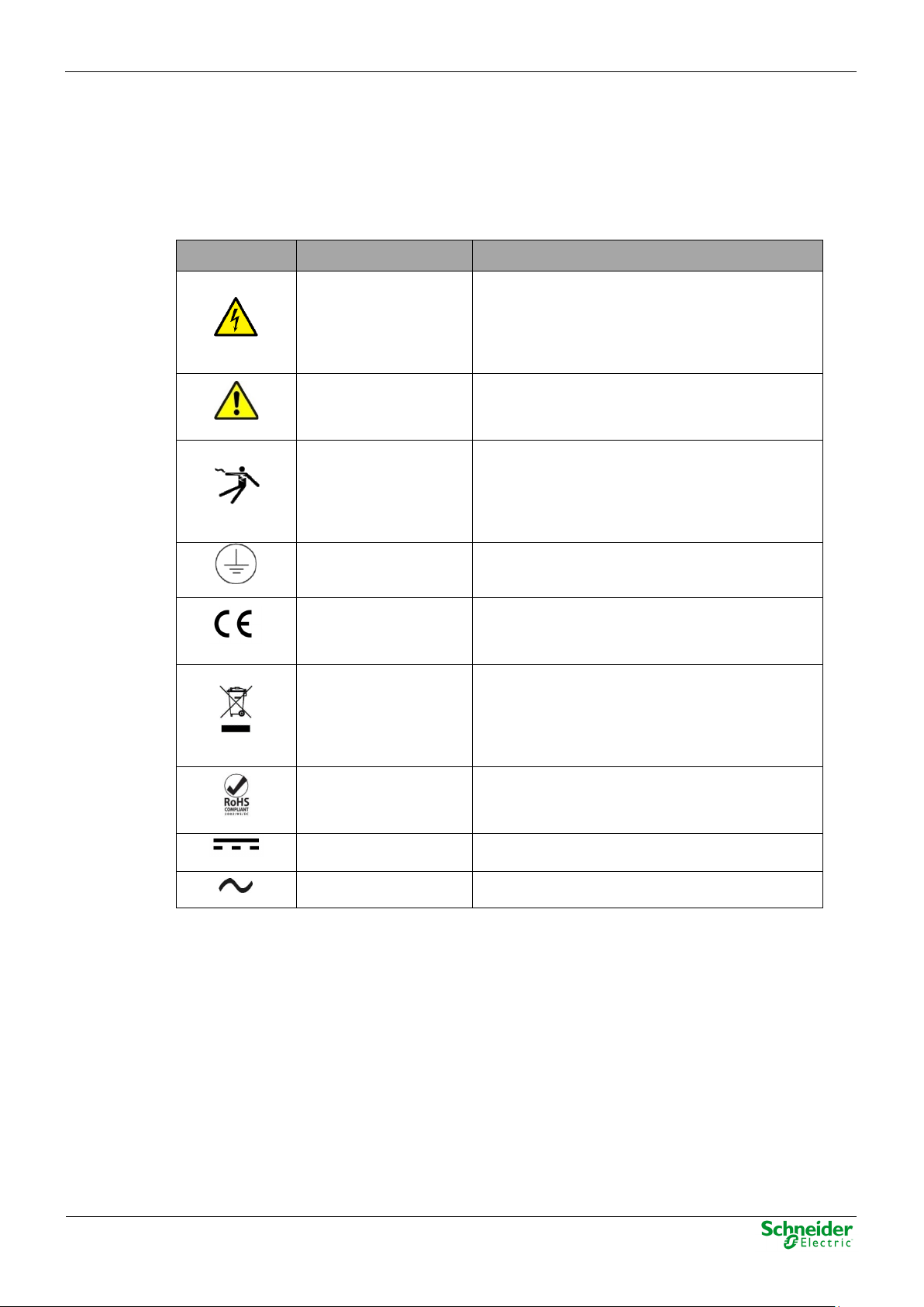
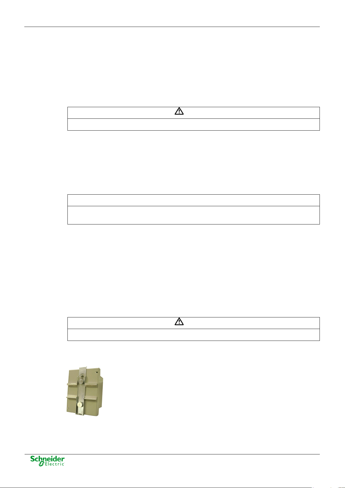
An electrical risk symbol with enough size must be included on the cabinet’s door or
on the barrier.
The following image shows an example:
Figure 1 - Barrier of protection for elements with high voltages.
Page 11
User Manual – HUe
24/09/2020
Pag 11
NOTICE
Terminals will not be accessible to the user directly once it has made the installation of the
WARNING
Don’t use liquid products of cleanliness due to the presence of active parts.
WARNING
connected to this screw.
WARNING
All electronic equipment with high voltage must be disconnected before dismounting a module
equipment. The cabinet will have to remain closed with key or the screen of installed protection.
The cabinet or installation must have a general switch placed just in the cable entry of the
installation (see paragraph 1.7.1 ).
For the cleaning of the equipment, it is recommended to remove the power and to use only a dry
cloth by the surface when it detects excessive presence of dust or any element deposited on the
surface.
Because of the variety of uses of the product, the managers of the application and use of this
controller device will have to take the measures to the fulfillment of all the safety requirements and
provision of each application. These requirements are according to the applicable laws,
regulations, codes and standard.
1.5 Earthing
Before energizing the equipment, it has to be earthed properly such as it indicates in the
sections 1.5.1 and 1.5.2 .
When installing the equipment, ground is the first thing that should be connected and the last
one that should be disconnected.
Saitel can be earthed for two distinct needs:
• For purposes of electrical safety (Protective Earth, PE).
• Improve the behavior in Electromagnetic Compatibility (EMC) and derive perturbations to earth
(functional Earth).
1.5.1 Electrical Safety
Only qualified personnel, with knowledge about hazards associated with electrical equipment is
allowed to install Saitel DR. In general, the installation will be following IEC 61010-1
recommendations in order to be compliant with this norm.
The modules must be installed on a metallic DIN Rail which is fixed on a metallic
surface. This metallic surface must have an M4 screw marked with this symbol.
According to the norm IEC 61010-1, the ground of the cabinet or installation must be
Saitel DR modules have a metallic enclosure offering protection for isolation faults.
from the DIN rail.
A dedicated connection with green/yellow wire should be used to have electric continuity to the
installation protective earth. Use a wire with adequate section according to IEC 61010.
Page 12
24/09/2020
User Manual – HUe
Pag 12
WARNING
According to Electrical Safety:
NOTICE
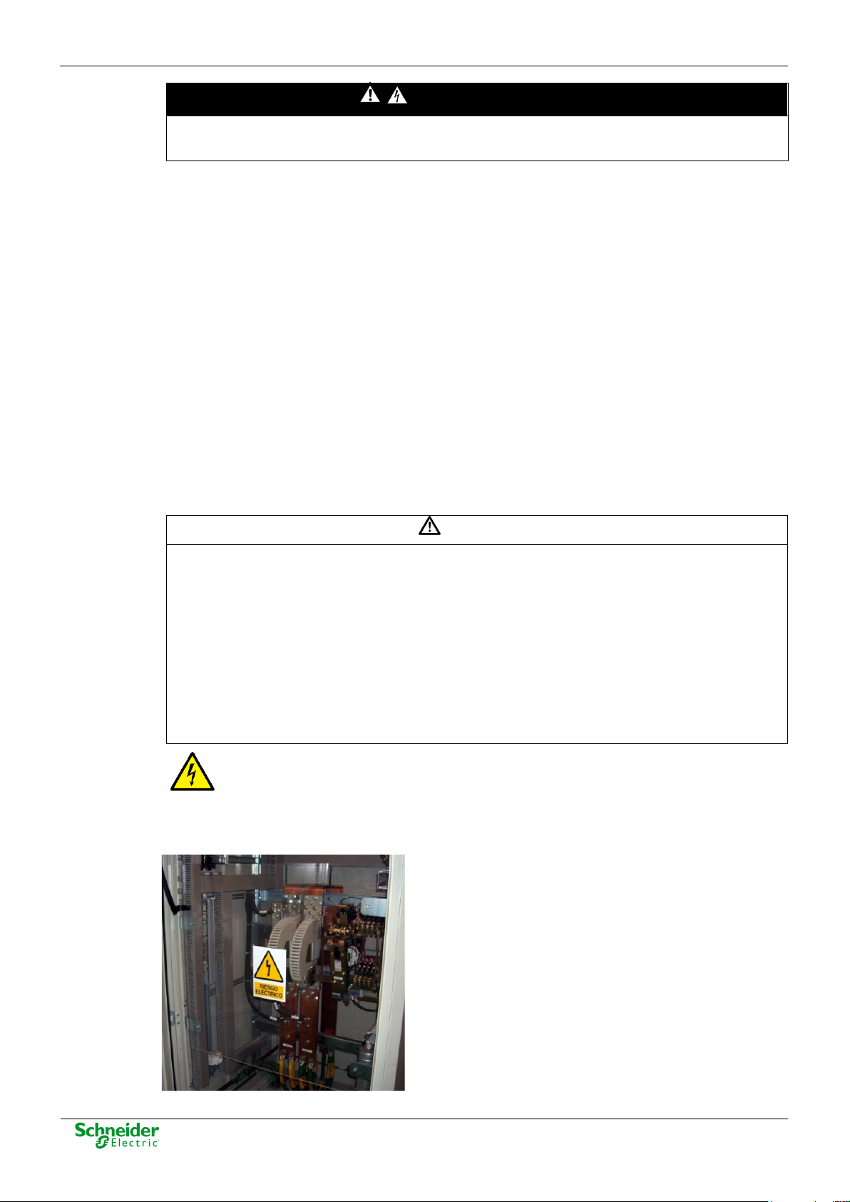
The DIN rail must have terminals of earthing (of yellow and green colour) necessary to connect
Figure 2 – Yellow and Green cable for earthing.
The design and installation of the cabinet is responsible for compliance with all the existing
international and national electrical codes concerning protective grounding of any equipment.
• The screw for ground must be exclusive for this use.
• The power voltage must be supplied by a power supply that offers double or reinforced
insulation against high voltages (higher than 50 V).
1.5.2 Functional Earth (EMC)
In this case the main rule is that the connection has to be done with wires of the lower possible
length to the shield or earth connection nearest. In this case the section of the driver is less
notable, moreover, it is advised of the use of flat wires or flexible conductive bands for a good
behavior EMC.
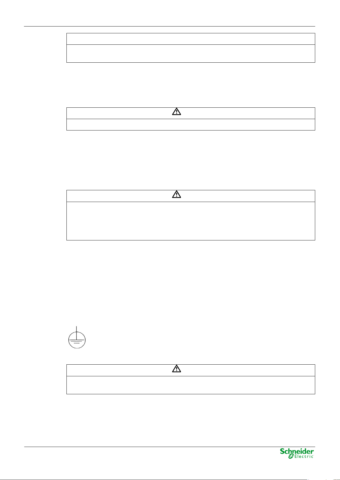
the terminals of PE (if it is present).
Figure 3 –Terminal for functional earth (EMC).
All Saitel DR modules with power or polarization connector have an exclusive terminal for earthing
EMC. These modules are HUe, HU_B, HU_A, HU_AF, XU, AB_DO, AB_DIDO and AB_SER with
external polarization.
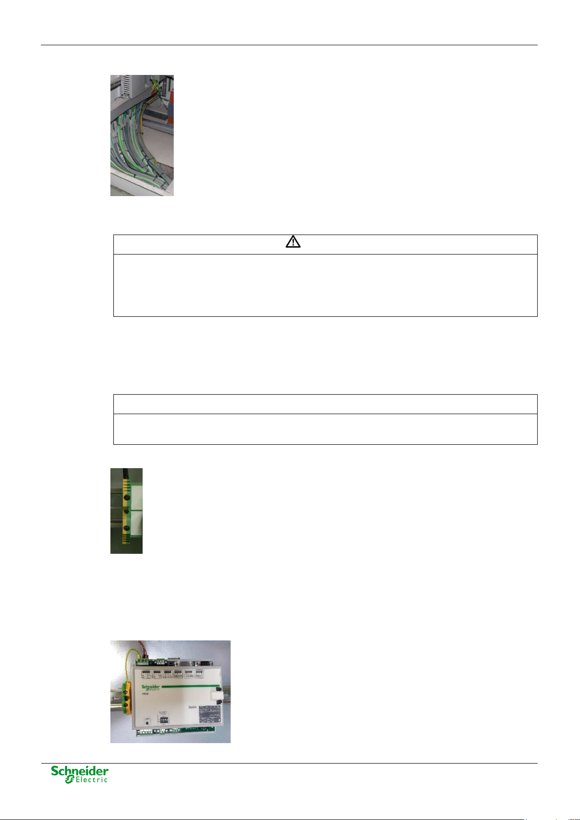
It must be connected as follows:
Figure 4 – Example of earthing for EMC.
Page 13
User Manual – HUe
24/09/2020
Pag 13
WARNING
The enclosure should ONLY be removed by authorized use and ONLY when is strictly
WARNING
The connection / disconnection switch must be installed in a fixed element (for example the wall
WARNING
This equipment has been designed ONLY for indoor use.
1.6 Handling Electronic Components
Like any electronic equipment, Saitel is susceptible to receive electrostatic discharges during the
handling. It is necessary to take the usual measures to minimize this risk, since serious damage to
the equipment can be caused, which may not be detected immediately but which may affect the
reliability of the product.
necessary, because this action has a risk for the equipment. The following precautions will be
taken:
• Before removing the enclosure, you must be equipotential with the equipment. You
must have a grounding bracelet and the device must be connected to ground as well
• Avoid touching the electronic. The board must be always manipulated for the edges.
• If the equipment has to be passed between two persons, both must be equipotential.
• Put the module always on an antistatic surface or on a surface equipotential with you.
• During the storage and transport, the module will remain in the packaging.
Not following these instructions can give like result that the equipment do not work
properly or even can damage the people or equipment.
1.7 Technical Specifications for Safety
1.7.1 Protective Elements
The cabinet's engineering and installation must include a general automatic switch next to the
cables' input in the cabinet; once the door is opened, high voltages must be interrupted inside. This
switch must be located at a place which is not accessible by a third person while the operator is
using the boards in the cabinet.
Moreover, the installation will incorporate a circuit breaker of 5A next to the cabinet protecting it
from possible overcurrent in the power supply.
Both switches will be labeled with the symbol O as "Off" and I as “On”.
of the cabinet) and it mustn’t break any earthing wire.
1.7.2 Environmental Conditions
The protection degree of the equipment is IP20.
If it is necessary for his use in some external surroundings, it has to mount in a cabinet or specific
accommodation that contributes at least a degree of protection IP54, protected against the dust
and water.
Page 14
24/09/2020
User Manual – HUe
Pag 14
WARNING
According to the standard 60950-1, all electrical safety tests have been done in an
NOTICE
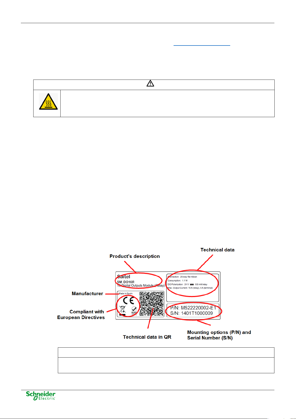
On the “Technical data” zone, you can see relevant information about the input and output
The electronic cards of the modules will be able to be tropicalized or no according to the
manufacturing option. The tropicalized used is the AVR80, of the company ABchimie. It can consult
all the technical information of this type of finishing in http://www.abchimie.com/
Other data to take into account about the environmental are:
• Altitude until 2000 m.
• Operation temperature range: Between -40 ºC and 70 ºC. (IEC 60068-2-1 and IEC 60068-2-2).
environmental temperature range of -40 ºC to 60 ºC. For higher temperature (> 60 ºC), the
module must be handled with care, since the metal surface could reach a dangerous
temperature for the user.
• Maximum relative humidity of 95%. (IEC 60068-2-30)
• Degree of pollution II. (IEC 60255-5)
• Overvoltage transitory until levels of Category III. (IEC 60255-5)
1.7.3 Storage Conditions
The continuous exhibition to some high levels of humidity during the storage can cause damages
to the electronic components and reduce the useful life of the equipment.
.
We recommend that, in the enclosure of storage, the relative humidity do not exceed 50%.
Before the installation of an electrical equipment, it is recommended to leave the necessary time for
the acclimatization of the environmental temperature.
1.8 Technical Label
Each Saitel product includes a technical label with the following information:
Figure 5 – Technical label.
voltage in the module. Any voltage greater than 50 V must be considered as a high voltage.
Page 15

User Manual – HUe
24/09/2020
Pag 15
NOTICE
Our products leave our factory in closed, sealed original packaging. If at receipt of the delivery
the other elements, and each one must be recycled according to the local regulation.
1.9 Packing and Unpacking
All Saitel modules are packaged separately in their own carton box and shipped inside outer
packaging. Use special care when unpacking the equipment. Don’t use force.
the transport packaging is open or the seal is broken, the confidentiality and authenticity of the
information contained in the products cannot be ensured.
The design revision and manufacturing options can be determined using the P/N included in the
packaging label on packaging.
After unpacking the equipment, inspect it visually to be sure it is in proper mechanical condition.
If the product needs to be shipped, the original packaging must be used, including foams and the
carton box. If the original packaging is no longer available, make sure that the packaging used is
according to ISO 2248 specifications for a drop height of 1 m.
1.10 Decommissioning and Disposal
When the product is marked with this symbol, it means that, at the end of its life
cycle, you mustn't dispose the product together with habitual residues. To avoid the
possible damage to the environment or to the human health that represents the
uncontrolled elimination of residues, please, separate the battery (if there is one) of
Page 16

24/09/2020
User Manual – HUe
Pag 16
2 General Description of HUe
Page 17

User Manual – HUe
24/09/2020
Pag 17
Content
2 GENERAL DESCRIPTION OF HUE ...................................................................... 16
2.1 SAITEL DR PLATFORM ......................................................................................... 18
2.2 HU
2.3 I
2.4 H
E FUNCTIONS IN THE ITB ................................................................................. 18
NTERFACES ......................................................................................................... 21
ARDWARE ARCHITECTURE .................................................................................. 22
Page 18

24/09/2020
User Manual – HUe
Pag 18
NOTICE
Please note Saitel DR does not support hot-swapping, that is, module replacements during
2.1 Saitel DR Platform
Saitel DR is a hardware platform by Schneider Electric. It consists of a set of equipment which
have been specifically designed for real-time control and automation applications. Saitel DR is a
high-technology platform which serves Schneider Electric’s business areas.
On this hardware platform, the Baseline Software Platform is installed. This software is used in
Saitel families (Saitel DP and Saitel DR) and other Schneider Electric products.
Other features identifying Saitel DR are:
• A DIN rail is used for the mechanical installation.
• The communication between the controls units integrated in a distributed system is mainly
established by Ethernet.
• The terminal blocks for field-connection are completely built into acquisition blocks.
Figure 6 – Saitel DR.
Saitel DR’s design has been optimized to meet the most demanding requirements of multiple
sectors:
• Safety and reliability requirements for power, gas and water supply, as well as sewage
treatment plants, etc.
• Compliance with electric safety, electromagnetic compatibility, and environmental standards.
• Centralized monitoring and control of geographically-distributed systems which support
hierarchical data acquisition and sharing networks.
• Local monitoring and control with data sharing capabilities of plant-distributed equipments.
• Quick troubleshooting, including the possibility of using programmable automation execution.
operation.
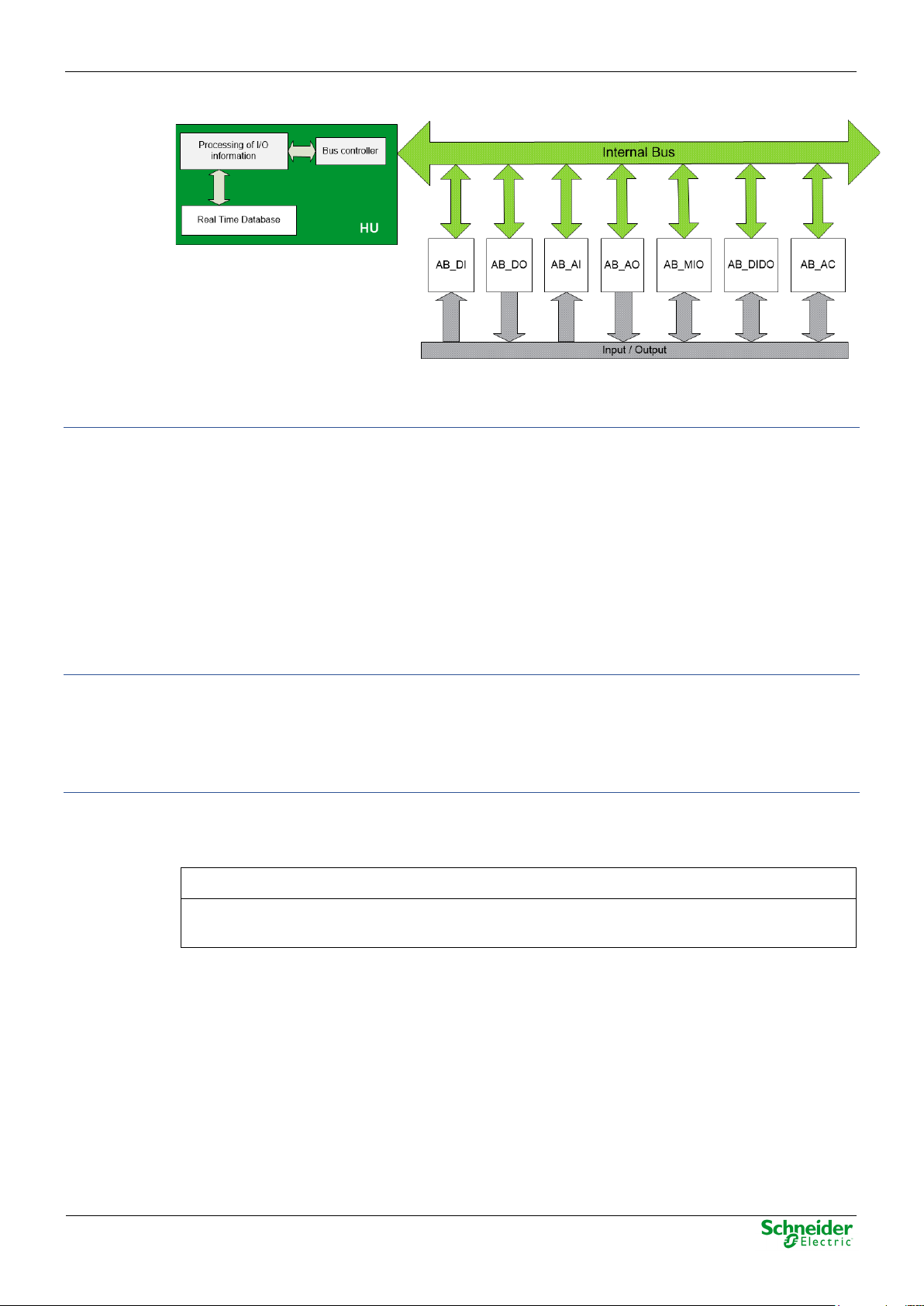
2.2 HUe Functions in the ITB
HUe is a high-performance CPU developed by Schneider Electric within the Saitel DR family. HUe
performs the control functions for the complete system, centralizes the information acquired by
other modules, and executes the programmable logic control, communication protocols and userspecific applications.
The communication with the acquisition modules in the ITB is established by an internal high-speed
bus that makes the system highly reliable even in noisy environments.
Page 19
User Manual – HUe
24/09/2020
Pag 19
NOTICE
The primary source is used to synchronize the ITB, if available. Otherwise, the secondary
ITB Controller
Figure 7 – Communication between HUe and ABs.
HUe controls and manages the following functions:
This block controls the operation of both the HU and the ABs connected to the HU through the bus.
These functions include:
• Operation mode monitoring. It performs functions as hardware and software Watchdog control,
the states control of the ABs and the HU and the provision of diagnostic information about the
ITB status through the LED indicators and several log files. These files can be consulted by a
user with sufficient privileges through SFTP or webApp.
• Interface with the operator through the console, webApp (for supervision and maintenance)
• Firmware upgrade by SFTP or webApp (using MNT port) or USB 2.0 port.
ITB Configuration
HUe maintains and manages the information that supports the real-time database, coreDb. In this
database, the I/O signals are related to the communication protocols signals. The configuration is
based on XML files that are generated with the Easergy Builder tool. These files are generated on
a PC and sent to the CPU via an SFTP connection through the MNT port.
ITB Synchronization
Up to two different synchronization sources can be configured. In this configuration is included the
priority level for each source, so there will be a primary and a secondary source. If both sources
are active, only the primary source will synchronize the system.
source is used.
The available synchronization sources are:
• A GPS connected to the COM1 port. The time received from the GPS is used to set the
and Easergy Builder (for configuration).
system’s clock and the RTC.
• An SNTP source through Ethernet. HUe can be used as SNTP server and client.
• Protocol: Most telecontrol protocols allow synchronizing to slave devices.
• Console: The user can set the system's time manually from the console terminal.
• IRIG-B: HUe can be used as a server and/or a client. The communication always will be made
with IRIG-B compliant devices.
Page 20

24/09/2020
User Manual – HUe
Pag 20
NOTICE
If the HUe is configured as IRIG-B server you have to include an AB_SER module in the ITB.
The IRIG-B signal will be send to client devices through the COM ports of this module. More
information in the AB_SER user manual.
If the synchronization source is not configured, the console device will always be created by
default. The console operates as the lowest priority when other source is configured.
ITB Communications
The HUe configuration includes information about definition and parameterization of
communications. For HUe you have:
• IEC101 master and slave.
• IEC104 master and slave.
• DNP 3.0 master and slave.
• IEC103 master.
• Modbus master and slave.
• IEC61850 client, Edition 1 and 2.
• IEC61850 server, Edition 2.
I/O Acquisition
HUe manages the information exchange with the ABs. Its main functions include:
• Processing I/O information, which offers an added value to the information exchanged with the
ABs.
• Accessing the internal bus to exchange information with the ABs.
• The HUe module has 4 digital inputs that can be used as 4 general-purpose digital inputs or as
2 specific-purpose digital inputs and 2 general-purpose digital inputs (more details below in this
manual).
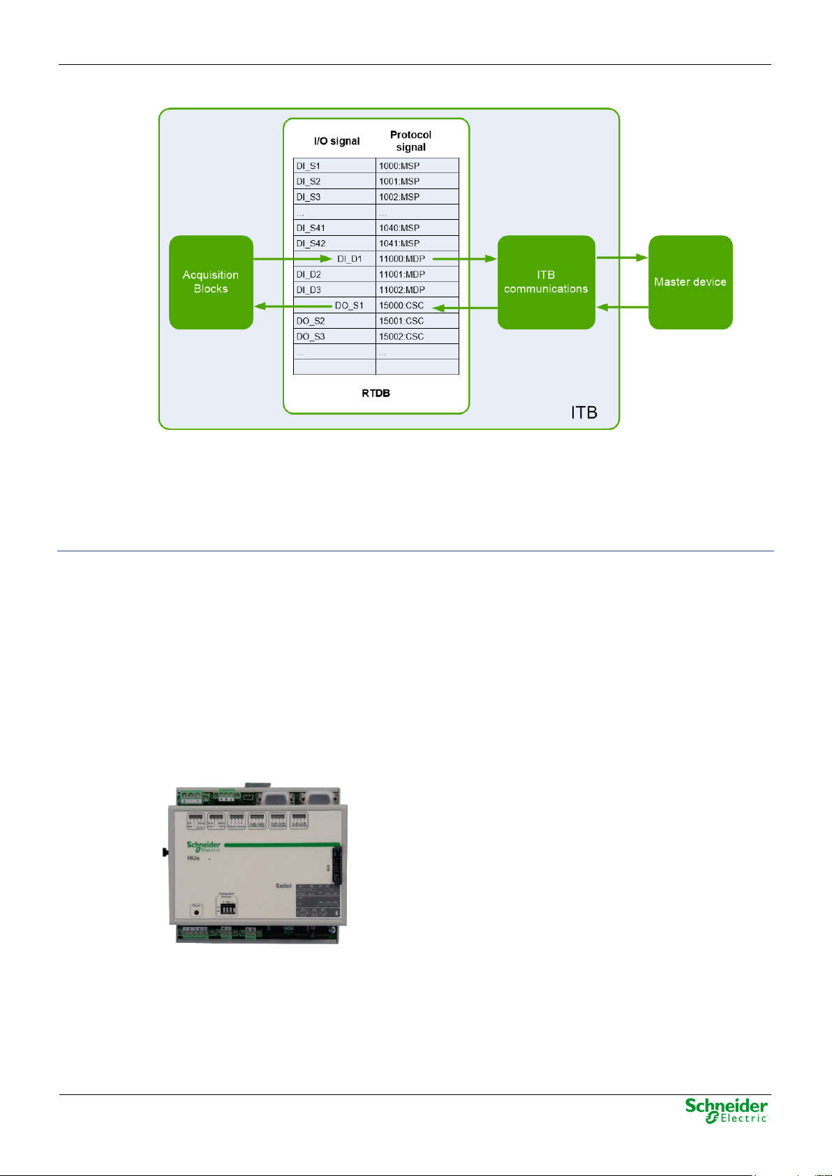
Real-Time DataBase (RTDB)
The core of the Baseline Software Platform is the real-time database or coreDb. It is a real-time
database which stores not only the information acquired from field devices, but also the information
about the status of HUe and ABs included in the ITB.
coreDb also relates the acquisition signals to the communication protocol signals. This database is
generated in the CPU by using the configuration information.
The information which is received from field in real time is processed, stored in the RTDB and then
related to the communication protocols signals of the ITB, which function is to transfer that
information to the master device.
Page 21
User Manual – HUe
24/09/2020
Pag 21
Figure 8 – coreDb operation example.
coreDb can also have as a source of information the result of a logic, which can be implemented by
a third-party software such as ISaGRAF® or within the database itself with an internal device of the
type "Formula".
Consult more information about this functionality in the Easergy Builder user manual.
Cybersecurity
The HUe module is supplied with a standard security policy, complemented with the definition of an
RBAC model (Role-Based Access Control). This model is defined and managed through a special
tool, CAE (EcoStruxure™ Cybersecurity Admin Expert.
2.3 Interfaces
The HUe module is a high-performance CPU, which offers superior performance to other Saitel DR
CPUs. It includes the Baseline Software Platform based on Linux operating system and with an
integrated cybersecurity brick.
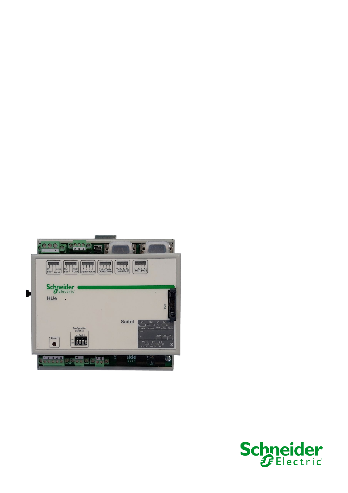
Figure 9 – HUe front view.
The main features of this module are:
• Power input between 24 and 48 V
, with tolerance of 20%.
DC
• A reset button integrated allowing the user to reset the module mechanically.
• It implements a security mechanism for data in memory (NVRAM) allowing to keep the
information for some time if the power is temporarily down.
Page 22

24/09/2020
User Manual – HUe
Pag 22
• 4 general-purpose digital inputs.
• Synchronization using: IRIG-B input, PPS signal (through a GPS), console or SNTP.
• A watchdog isolated output is available and can be used according to the requirements of the
system.
• A copper Fast-Ethernet port for configuration and maintenance (10/100BaseT).
• Two additional Fast-Ethernet ports, which can be copper (10/100BaseT) or fiber optic
(100BASE-FX) depending on the mounting options.
• Two RS-232 non-isolated communication ports. COM1 allows modem control but COM2 does
not.
• One RS-485 isolated communication port.
• One console port using a miniUSB connector or bluetooth.
• One USB 2.0 connector for software upgrading.
• SD slot.
2.4 Hardware Architecture
The HUe module is composed by two or three electronic boards, depending on the manufacturing
options.
Figure 10 – Electronic boards in HUe.
These electronic boards and the metallic enclosure makeup the HUe module.
This information is shown in the technical label on the module with the Part Number (P/N):
Page 23
User Manual – HUe
24/09/2020
Pag 23
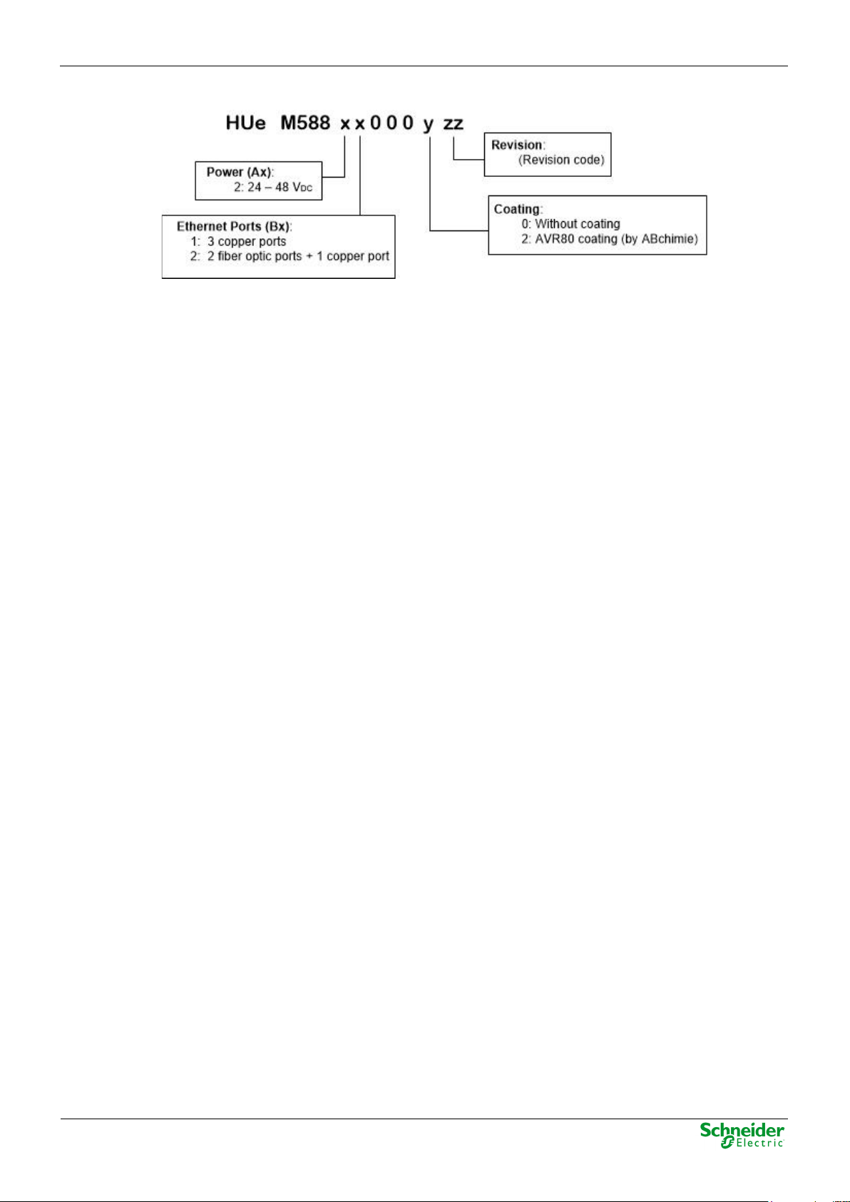
Figure 11 – Part Number description.
If the module is manufactured without optic fiber, only two boards will be mounted.
Ordering options:
• (Ax) Version of the microprocessor: Lite / Pro.
• (Bx) Power supply. The module can be powered with 24 V
or 48 VDC, both ±20%.
DC
Page 24

24/09/2020
User Manual – HUe
Pag 24
3 Physical Mounting & Installing
Page 25

User Manual – HUe
24/09/2020
Pag 25
Content
3 PHYSICAL MOUNTING & INSTALLING ............................................................... 24
3.1 ITB INSTALLATION ............................................................................................... 26
3.1.1 H
3.1.2 HU
3.1.3 P
3.1.4 M
3.2 W
3.2.1 W
3.2.2 P
3.2.3 D
3.2.4 S
3.2.5 E
3.2.6 IRIG-B
3.3 C
3.4 E
3.5 C
3.6 LED
ANDLING MODULES ..................................................................................... 26
E LOCATION IN THE ITB ............................................................................ 26
OWER SUPPLY REQUIREMENTS ................................................................... 26
OUNT AND DISMOUNT PROCEDURES ........................................................... 26
IRING HUE ........................................................................................................ 27
IRING RECOMMENDATIONS ......................................................................... 27
OWER AND RESET ....................................................................................... 28
IGITAL INPUTS ............................................................................................ 29
ERIAL COMMUNICATIONS ............................................................................. 30
THERNET COMMUNICATIONS........................................................................ 32
AND WATCHDOG OUTPUT .................................................................. 34
OMPACT-FLASH CARD ....................................................................................... 34
XPANSION .......................................................................................................... 35
ONFIGURATION SWITCHES .................................................................................. 36
INDICATORS ................................................................................................. 36
Page 26
24/09/2020
User Manual – HUe
Pag 26
WARNING
Electrostatic discharges may damage semi-conducive devices within the module.
NOTICE
In order to minimize the adverse effects of noise and heat, it is recommended to install the ITB’s
WARNING
It is important to assure that handling is always done while the ITB elements are unpowered.
3.1 ITB Installation
3.1.1 Handling Modules
Please note the following precautions to avoid electrostatic damages:
• You should never touch the pins of the bus connector.
• You should keep the module in its packaging box when unused.
3.1.2 HUe Location in the ITB
The HUe module must always be the first module in the ITB, that is, it must be mounted in the first
position of the first DIN rail, being the bus initiator in the ITB.
The HU can only be found in the second position of the DIN rail, if the ITB requires processing
redundancy. In this configuration, there is a main DIN rail in which two redundant HU modules are
installed and connected to the acquisition ITB by means of an Ethernet network; the system’s bus
is not used in this case.
head unit as far as possible from other modules handling alternating current and high voltages.
3.1.3 Power Supply Requirements
To calculate the ITB’s power supply requirements, you will need to consider the power
consumption of each module. The modules’ power consumptions must be added plus a safety
margin (min. 20%). Each row in the ITB is powered independently thought the HUe (first row) or XU
(second and following rows) module.
In order to avoid ITB overload, the power supply performance should also be considered (typically,
70-90%).
The power consumption data is detailed in the technical specifications table of each module’s user
manual and in the technical label on the equipment.
3.1.4 Mount and Dismount Procedures
Saitel DR modules have a DIN-rail bracket at the rear side that allows mounting on a DIN rail.
Figure 12 – Mount bracket on DIN rail.
The mounting procedure is described below:
• Switch off the power supply.
• Attach the module’s rear bracket on the upper DIN rail.
Page 27
User Manual – HUe
24/09/2020
Pag 27
• Press the lower front panel gently until a click confirms that the bracket is fit on the rail.
• Verify the module is anchored firmly to the rail, although lateral movement is possible.
Figure 13 – Saitel DR module on a DIN rail.
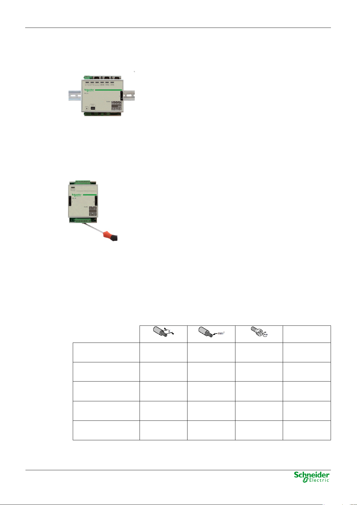
The module is dismounted from the DIN rail as follows:
• Switch off the power supply.
• If necessary, disconnect the bridge(s) connecting the module to the system bus.
• Holding the module by the front panel, push the upper metal tab downward. The user can also
pull the tab down using for example a screwdriver as shown:
• Pressing the tab, remove the module from the lower DIN rail.
• Once detached, the module can be removed easily.
3.2 Wiring HUe
3.2.1 Wiring Recommendations
The following table shows several wiring recommendations for signals, communications and power:
Power 7 mm
Digital Inputs 7 mm
RS-485 7 mm
IRIG-B 7 mm
1.5-2.5 mm²
15-13 AWG
1.5 mm²
15 AWG
1.5 mm²
15 AWG
1.5 mm²
15 AWG
0.5 Nm Copper
0.5 Nm Copper
0.5 Nm
0.5 Nm Copper
Type
Copper,
shielded
Watchdog 7 mm
The following section describes each HUe interface, including functionality and wiring when it is
required.
1.5 mm²
15 AWG
0.5 Nm Copper
Page 28
24/09/2020
User Manual – HUe
Pag 28
NOTICE
Follow all wiring recommendation for EMC included in Saitel DR Platfom user manual.
NOTICE
The maximum power to be supplied to the rest of modules in the same row by the HUe module
WARNING
For safety reasons, the use of ferrules on power input cables is recommended to avoid possible
WARNING
For safety reasons, before connecting the aerial terminal to the module, it is recommended:
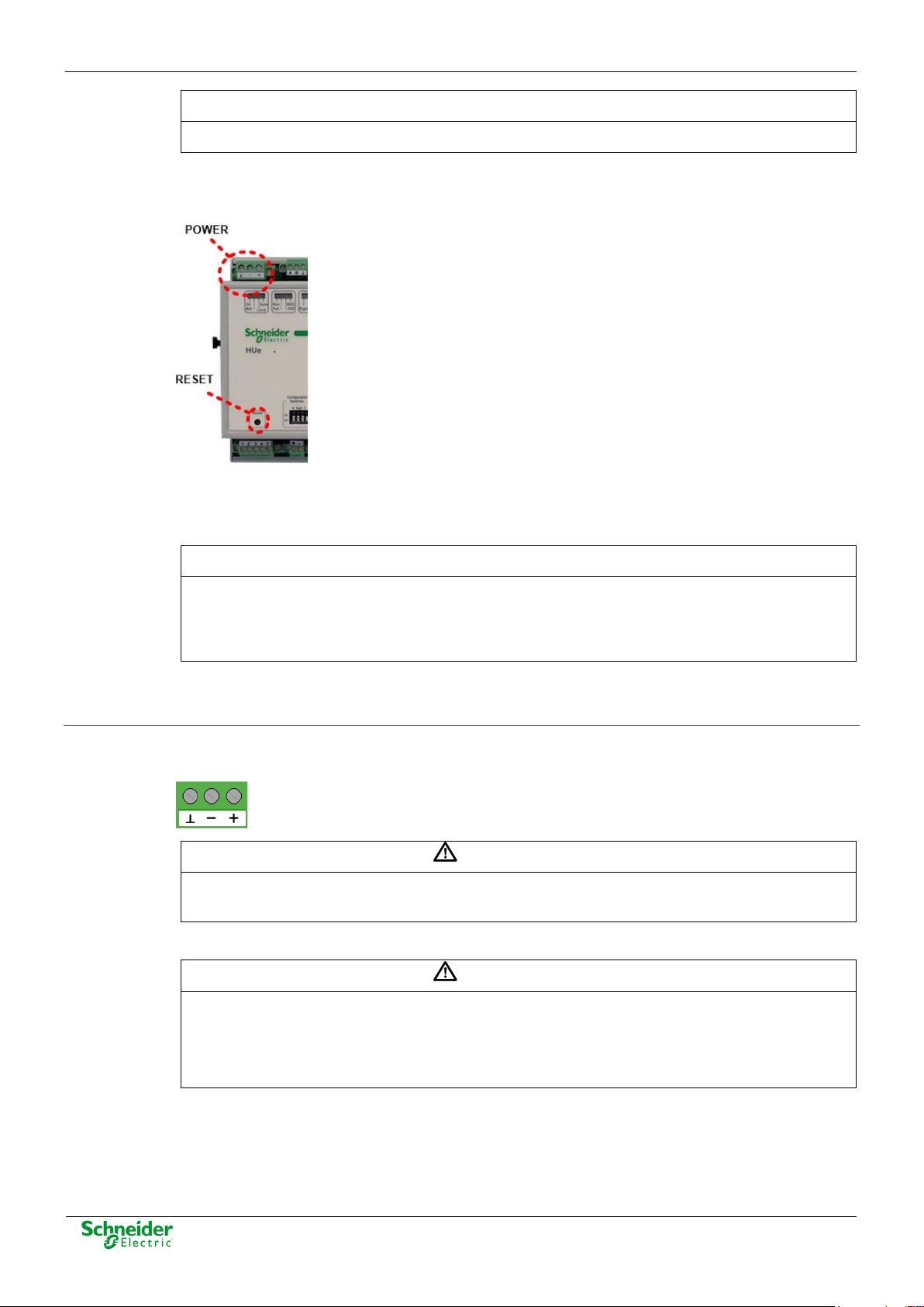
3.2.2 Power and Reset
Figure 14 – Power and Reset.
In the upper left area you can observe the power supply input terminal for the first row in the ITB.
There is a DC/DC converter, next to the filtering electronic components, which is used to power
both the HUe module itself and all the AB modules assembled on the same row.
Power Wiring
is 10 W. If the modules to be assembled on the ITB require a higher power, then, you will need
to split the ITB into several rows, always observing the above-mentioned maximum power
allowed for each row.
A Reset button is included in this block allowing the user to reset all the ITB.
The POWER connector must be used as power input. The input voltage range is 24 to 48 VDC, with
a tolerance of ±20%.
short-circuits.
From left to right, the connecting order must be: functional Earth, negative and positive terminal.
• To check that the voltage between the positive and negative poles does not exceed the
maximum operating voltage (see the technical table in chapter 6).
• To check that the polarity has not been inverted according to the label on the terminal.
Page 29
User Manual – HUe
24/09/2020
Pag 29
WARNING
Before doing any local operation, for safety reasons, the operator MUST:
WARNING
These signals must not be connected to equipment that are outside the cabinet. Failing this
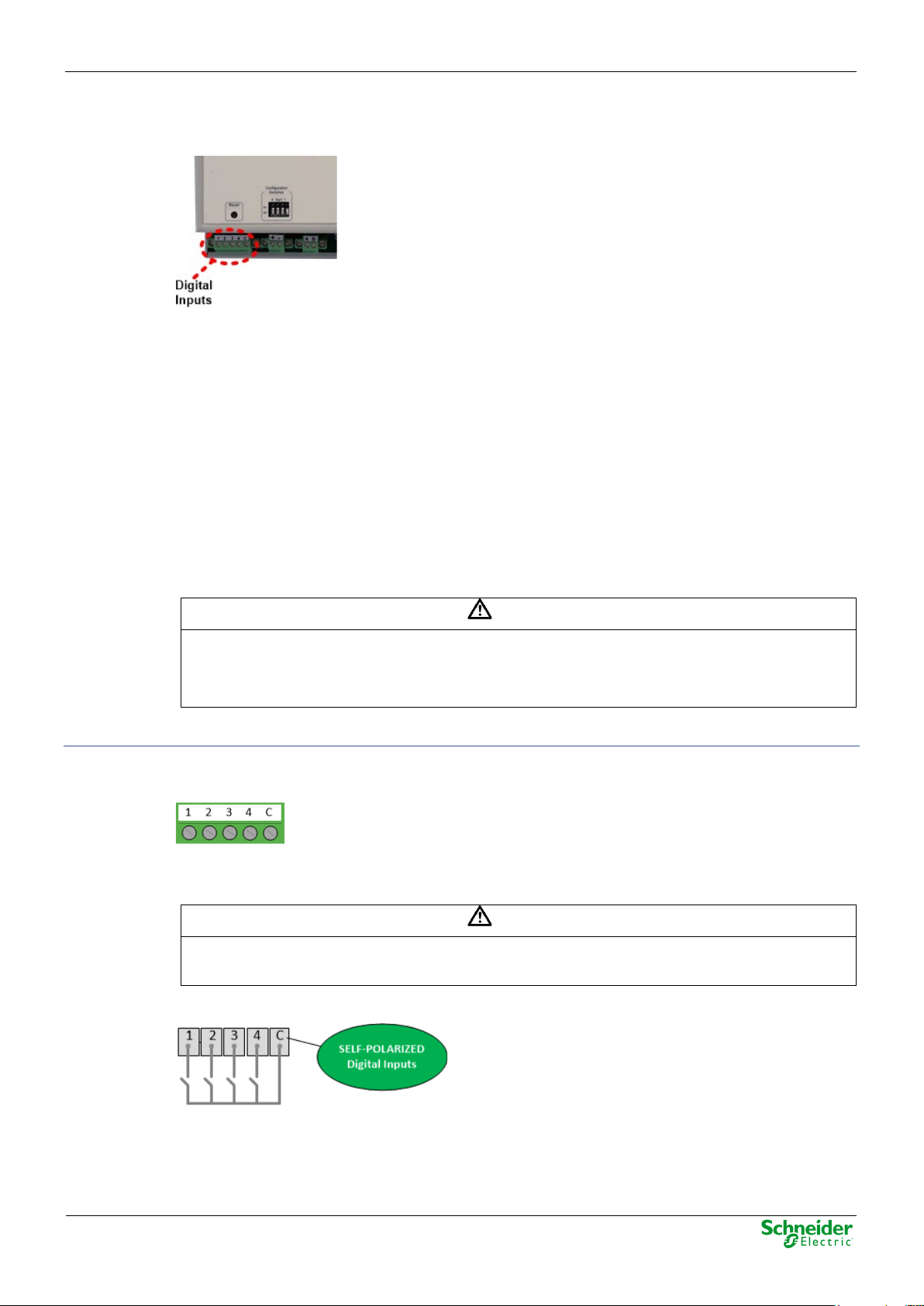
3.2.3 Digital Inputs
Figure 15 – General-purpose digital inputs.
HUe has 4 digital inputs located in the lower left, only configurable as single inputs. These signals
are useful to inform the operator about some malfunction in the system.
The digital inpus 1 and 2 can be used for the following purposes:
• Digital input 1: This signal provides the HUe module with information about the digital inputs’
polarization status of the ABs installed in the ITB. When the signal is active, the polarization of
all digital signals is correct. If the signal is disabled, the HU will understand that there is a
polarization fault.
• Digital input 2: If this signal is enabled, the HUe module will interpret that the ITB is working in
LOCAL mode, whereas if it is disabled, the ITB is operating in REMOTE mode. When the ITB
is in LOCAL mode the commands are disabled.
To use these two signals with the purpose described above, they must be defined in the database
following the instructions included in paragraph 4.5.1 of this manual.
Digital Inputs Wiring
Use AUX DI terminal in order to use the general-purpose digital inputs. These signals are selfpolarized, that is, they do not need an external polarization source.
These digital inputs are designed for internal use within the cabinet where the HUe module is
installed.
instruction could modify EMC behavior of the equipment.
The following figure illustrates how each input receives the polarization through the common:
• To be sure that the "Local" LED on HUe is lit.
• To be sure that the secondary relays are de-energized.
Page 30
24/09/2020
User Manual – HUe
Pag 30
WARNING
These digital inputs are internally polarized. Please, DON’T CONNECT to other power supply.
Failure to observe this instruction can result in equipment damage.
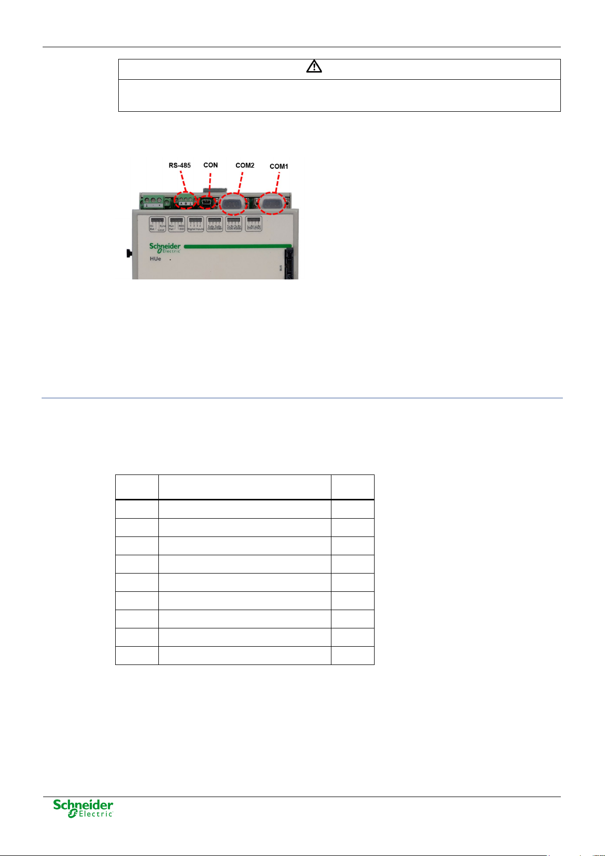
3.2.4 Serial Communications
Figure 16 – Serial communication ports.
• COM1 and COM2: non-isolated RS-232 communication ports for general-purpose. Both ports
use male DB-9 connector.
• CON: Console port with miniUSB connector.
• RS-485: Isolated TS-485 communication port.
• Bluetooth: Wireless connection. Currently it can only be used for the console.
RS-232 Communications Wiring (COM1 and COM2)
All modem signals are available in COM1 port. COM2 only uses RTS and CTS signals. The
maximum speed in both ports is 115200 bps.
Following tables show the pinout for both connectors:
Table 2 – Pinout of COM1
Pin Description I/O
1 DCD – Data Carrier Detect I
2 Rx – Data Reception I
3 Tx – Data Transmission O
4 DTR – Data Terminal Ready O
5 GND – Ground -
6 DSR - Data Set Ready I
7 RTS – Request to Send O
8 CTS – Clear to Send I
9 RI – Call indicator I
Page 31

User Manual – HUe
24/09/2020
Pag 31
NOTICE
COM1 can receive a pulse per second signal (PPS) through pin 8, so it must be used as the
NOTICE
When using a GPS synchronization device, it is always advisable to wire the PPS signal to
WARNING
The installer should check that the cable connected to each COMx port is correct. It is also
Table 3 – Pinout of COM2
Pin Description I/O
1 Not connected -
2 Rx – Data Reception I
3 Tx – Data transmission O
4 Not connected -
5 GND – Ground -
6 Not connected -
7 RTS – Request to Send O
8 CTS – Clear to Send I
9 Not connected -
GPS input, if required. The input PPS signal must be valid for RS-232 levels.
The validated GPS devices to be connected to the COM1 port are GPS35 (Garmin) and GPS16
(Garmin).
Some GPS devices don’t allow to use PPS signal.This operation mode implies that the
synchronization accuracy will be lower. It can produce a desviation of up to 10 ms in the generation
of the signal.
achieve the highest accuracy in the synchronization.
recommended to use identification tags on the cables to avoid errors.
Redundancy Wiring (COM1 and COM2)
For redundant system, both HUe can be connected using COM1 and COM2 ports. The following
pinout must be considered (other pins should not be connected):
Figure 17 –Pinout of the cable for redundancy.
Page 32

24/09/2020
User Manual – HUe
Pag 32
Console Port Wiring (CON)
The following table shows the pinout of the miniUSB port for the console:
Table 4 – Pinout of the console port.
Pin Name Wire color I/O
1 - Not connected
2 Data - White O
3 Data + Green I
4 Mode detection - Not connected
5 Ground Black Ground
RS-485 Wiring (RS-485)
This terminal block is used to communicate with other equipment through a 2-wire RS-485
communication (Half-Duplex). The figure below shows the pinout of this terminal:
The relationship between this 3-poles terminal and the SM_SER’s DB9 connector is the following:
Table 5 – 2-wire RS-485 to DB9
HUe connector DB9 connector
A Pin 9 (Y)
B Pin 8 (Z)
Ground Pin 5
3.2.5 Ethernet Communications
Figure 18 –Ethernet communication ports.
• MNT: Fast-Ethernet port (10/100BaseT) for maintenance purpose. It uses a RJ-45 connector.
• LAN1 and LAN2: Fast-Ethernet communication ports using copper or fiber optic depending on
the manufacturing options.
o Copper ports allow 10/100 BaseT IEEE 1588, with a RJ-45 connector.
o Fiber optic ports allow 100Base-FX with SFP connectors.
Page 33

User Manual – HUe
24/09/2020
Pag 33
WARNING
The installer should check that the cable connected to each Ethernet port is correct. It is also
WARNING
Each network segment cable length may be up to 100 m.
recommended to use identification tags on the cables to avoid errors.
Ethernet Wiring – Copper ports
The pinout for RJ-45 connector is the following:
Table 6 – Pinout of the copper ports.
Pin Name Description TIA/EIA 568A TIA/EIA 568B
1 BI_DA+ Bi-directional pair A+ (TX)
2 BI_DA- Bi-directional pair A- (TX)
3 BI_DB+ Bi-directional pair B+ (RX)
4 BI_DC+ Bi-directional pair C+
5 BI_DC- Bi-directional pair C-
6 BI_DB- Bi-directional pair B- (RX)
7 BI_DD+ Bi-directional pair D+
8 BI_DD- Bi-directional pair D-
TIA/EIA 568A and TIA/EIA 568B are two color codes used for wiring eight-position RJ45 modular
plugs. Both are allowed under the ANSI/TIA/EIA wiring standards. The only difference between
both codes is that the orange and green pairs are interchanged.
Ethernet Wiring – Fiber Optic Ports
If fiber optic is selected in manufacturing options for LAN1 and LAN2, they have to mount a SFP
transceiver with LC connector. These transceivers aren’t included with HUe.
White/Green
Green
White/Orange
Blue
White/Blue
Orange
White/Brown
Brown
White/Orange
Orange
White/Green
Blue
White/Blue
Green
White/Brown
Brown
The following figure shows two connectors which could be used in LAN1 and LAN2:
The following models are recommended:
• Models: HFBR-57E0PZ and HFBR-57E0APZ
o Full compliance with the optical performance requirements of 100Base-FX version of
IEEE802.3u.
o Operates with 62.5/125 μm and 50/125 μm multimode fiber, with a LED light
source of 1300 nm.
o Maximum link lenght: 2 km.
o Operating temperature: From -40 ºC to +85 ºC (only HFBR-57E0APZ)
Page 34

24/09/2020
User Manual – HUe
Pag 34
WARNING
The watchdog output is not designed to be wired as a field output. This output was designed to
3.2.6 IRIG-B and Watchdog Output
Figure 19 –IRIG-B and WD output connectors.
IRIG-B Wiring
This terminal block is used to receive an IRIG-B claqsignal (non modulated TTL - 5V) which can be
used by the CPU to synchronize the ITB. The input impedance is 600 Ohm.
The connector for IRIG-B has the following pinout:
HUe can be set as an IRIG-B client and/or server, according the standards IRIG-B002, 003, 006
and 007.
Watchdog Wiring (WD)
A watchdog output (identified as WD and labeled as B5) is available in HUe for system monitoring.
It is implemented as follows:
• solid-state relay (normally open)
• supporting a maximum voltage of 250 V.
• current of 200 mA.
The relay status depends on the FAIL_RTU supervision signal. A normal value of this signal is 0,
and value 1 is associated to the detection of a malfunction in the system.
be connected to a local device inside the same cabinet. The connection wire must be shorter
than 3 meters.
3.3 Compact-Flash Card
Figure 20 – Slot for SD card and USB connector.
The slot for the SD card is located on the left side of the module. This card can be used for mass
storage of data, for example, the event log or configuration files.
Page 35

User Manual – HUe
24/09/2020
Pag 35
NOTICE
For P/N E7 and later, this ejector is not mounted. To extract the compact flash card, use an
WARNING
Turn off all power supplying this equipment before working on or inside it. Consider all sources
NOTICE
Before disconnecting the slave modules from the bus (disconnecting the flat ribbon) the ITB
The slot for the Compact-Flash card is located on the left side of the module. This card can be
used for mass storage of data, for example, the event log.
The following Compact Flash card have been validated (both with capacity of 512 MB):
• Swissbit manufacturer, model SFCF0512H1BK1MT-I-MS-553-SMA.
• Apacer manufacturer, model AP-CF512ME3NR-ETNRQ.
If necessary, to extact the compact flash card, use the ejector located at right of the slot.
appropiate tool, for example a tweezers for electronic.
If the CF ejector is not available for the module and there is some problem to access the card, you
can remove de enclosure and access to the card as follow:
of power, including the possibility of back feeding.
3.4 Expansion
Through a flat ribbon connector, the CPU starts the data and power bus, expanding it to the other
modules.
Figure 21 – Expansion bus connector.
must be unpowered.
Page 36

24/09/2020
User Manual – HUe
Pag 36
3.5 Configuration Switches
There are 4 configuration switches on the front of the module. They are numbered 1 to 4 from the
left to the right.
Figure 22 – Configuration Switches.
This group of switches allows:
• Restoring the manufacturing default configuration.
• Enabling the automatic execution of the addressing procedure (AAP).
• Executing the AAP automatically when the ITB starts.
As is indicated on the label, the switch is in position ON if is up and OFF when is down.
These switches can be used as follow:
• Switch 4: It restores the factory IP configuration. If switch 4 is ON when HUe starts, the
network configuration will be restored for all Ethernet ports. If the network configuration file
(netConfig.xml) exists, it will be renamed to old_netConfig.xml. The default IP addresses are
indicated in paragraph 4.1 .
• Switch 3: It enables or not the automatic execution of the AAP:
o On: Enabled. When the ITB starts, the AAP procedure is automatically executed.
o Off: Disabled. The AAP procedure has to be executed with a command if it is
required. This command may be executed depending on the position of switch 2.
• Switch 2: It allows or not the execution of AAP:
o On: Allowed. The AAP can be executed.
o Off: Not allowed. The AAP cannot be executed either automatically or manually.
• Switch 1: Reserved. It must be in OFF position.
3.6 LED Indicators
There are 24 light indicators (LED) on the front of the module:
Figure 23 – LED indicators
Page 37

User Manual – HUe
24/09/2020
Pag 37
NOTICE
There is not a LED associated to the MNT port.
The information by the LED indicators includes:
• General status of the module (On, Bat, Local and Sync)
• Configuration and acquisition status (Run, Fail, DIO and RED)
• Status of the 4 general-purpose digital inputs (Digital Input x).
• Transmission/Reception in COM1, COM2, CON and RS-485 ports (Tx and Rx).
• Communications in the Ethernet ports LAN1 (ETH1) and LAN2 (ETH2).
HUe’s LED provide the following information to the operator:
Blink
On
Off
Table 7 – LED indicators.
LED Status Description Recommended action
On
Powered. -
Unpowered. Connect the module to a power supply
according to the input voltage of the
module.
Bat
The supercapacitor is discharged. While this
led is on, the system cannot keep the data in
memory if a power down occurs.
Normal state. If the supercapacitor is fully
Switch 1 must be turned OFF. The led will
turn off when the supercapacitor is
loaded.
charged, data in memory can be kept for 8
hours (at 25 ºC) if a power down occurs.
Local
RTU in LOCAL mode. Digital outputs are
disabled in the ITB.
RTU in REMOTE mode.
Sync
The system uses an external synchronization
source.
Any external synchronization source is being
used.
Run
Fail
RTU operative, with configuration or not.
RTU not operative. Use the console tool in order to check if
RTU not configured or with errors. Use Easergy Builder and load a
A correct configuration is loaded in the CPU.
DIO
There is at least one module in Fail status in
the ITB.
All modules in the ITB are OK.
the message “CONF OK” is shown. The
supervision signal DOING_WELL must be
defined in coreDb and set to 1.
configuration without errors in the CPU.
Identify the module with problems and
perform the recommended actions. More
information in the user manual of the
module in fail status.
Page 38

24/09/2020
User Manual – HUe
Pag 38
LED Status Description Recommended action
RED.
Digital
Inputs x
Tx
Rx
Li
Ac
Redundant system and this is the HUe HOT.
Redundant system and this is the HUe
STANDBY.
Non redundant system or configuration.
The digital input x is activated.
The digital input x is deactivated or not
defined in coreDb.
The port COMx/CON/RS485 is transferring.
The port COMx/CON/RS485 is not
transferring.
The port COMx/CON/RS485 is receiving.
The port COMx/CON/RS485 is not receiving.
The port ETHx has a physical connection.
The port ETHx has not a physical
connection.
There is a channel activity through the ETHx
port.
There is not a channel activity through the
ETHx port.
Page 39

4 Configuration & Maintenance
Page 40

24/09/2020
User Manual – HUe
Pag 40
Content
4 CONFIGURATION & MAINTENANCE ................................................................... 39
4.1 GETTING STARTED ............................................................................................... 41
4.1.1 U
4.1.2 F
4.1.3 N
4.1.4 E
4.2 C
4.2.1 CAE
4.2.2 U
4.2.3 R
4.2.4 S
4.3 ITB
4.4 L
4.5 T
4.5.1 G
4.5.2 F
4.6 W
4.6.1 C
4.6.2 C
4.6.3 R
4.6.4 C
4.6.5 E
4.6.6 C
SING THE CONSOLE .................................................................................... 42
ILE SYSTEM ................................................................................................ 44
ETWORK CONFIGURATION (IP / ROUTER / FIREWALLS) .................................. 45
NVIRONMENT VARIABLES ............................................................................. 48
YBERSECURITY .................................................................................................. 48
AND RBAC ........................................................................................... 49
SERS ......................................................................................................... 49
OLES ......................................................................................................... 50
ECURITY EVENT LOG ................................................................................... 52
ADDRESSING (AAP) ...................................................................................... 53
OCAL ACQUISITION ............................................................................................. 54
REATMENT OF LOCAL ACQUISITION SIGNALS ....................................................... 54
ENERAL-PURPOSE DIGITAL INPUTS .............................................................. 55
IELD SIGNALS ............................................................................................. 55
ORKING WITH HUE IN EASERGY BUILDER ........................................................... 56
REATING A RTU BASED ON HUE .................................................................. 56
ONFIGURING A REDUNDANT RTU ................................................................. 57
EADING THE CONFIGURATION FROM THE HU ................................................ 58
REATE A NEW CONFIGURATION ................................................................... 58
DITING THE CONFIGURATION ........................................................................ 59
OMMUNICATIONS ........................................................................................ 60
4.6.7 CONFIGURING HUE COMMUNICATION CHANNELS ............................................ 60
4.6.8 C
4.6.9 S
4.6.10 U
4.6.11 PLC
4.6.12 S
4.6.13 R
4.6.14 L
4.6.15 G
4.6.16 T
ONFIGURING HUE LINK CONFIGURATION ...................................................... 61
YNCHRONIZATION ....................................................................................... 62
SING FORMULAS ....................................................................................... 65
CONFIGURATION ................................................................................. 65
UPERVISION .............................................................................................. 65
EDUNDANCY ............................................................................................. 68
OCAL ACQUISITION CONFIGURATION .......................................................... 71
ENERAL PURPOSE DIGITAL INPUTS ............................................................ 72
RANSFERRING THE CONFIGURATION TO THE RTU ....................................... 73
Page 41

User Manual – HUe
24/09/2020
Pag 41
NOTICE
We recommend using the Engineer user to perform configuration tasks with Easergy Builder
4.1 Getting Started
HUe is supplied with a basic configuration, which will help us have a first contact with the system.
To get started, you need to know the following data:
Default IP Addresses
Table 8 – Default IP Addresses.
Port Description IP Subnet Mask
LAN1 Operating system's eth0 port. 10.1.1.1 255.0.0.0
LAN2 Operating system's eth1 port. 192.168.1.1 255.255.255.0
User
MNT
In accordance to the policy provided with the CAE tool, the default users which can log into the
system are:
Table 9 – Default users.
User Level User Password Description
Operator Operator Operator1!
Engineer Engineer Engineer1!
Installer Installer Installer1!
Operating system's eth2 port. This is the
maintenance dedicated port.
This user can view most of the system's
information (data, syslog, events, settings…) It
can write to coreDb, but it does NOT have
access to security parameters.
This user can view and modify all the system
information, except for the security parameters. It
can also access the operating system's console,
although it cannot execute Saitel commands.
This user can view and modify all the system
information, except for the security parameters.
In the console, it can only access the BLMon
application and Saitel commands.
192.168.2.1 255.255.255.0
This user level can read coreDb settings and
Viewer Viewer Viewer1!
Administrator SecurityAdmin Security1!
and the Installer user to use the console.
It is possible to execute console commands with the Engineer user as follow:
Activate the command terminal with: tty > /tmp/BLCMD
Execute the command: echo "claqVersion" > /tmp/BLCMD
This command provides the software version installed on the ITB modules.
data and can connect to webApp. It cannot make
changes to settings or to the coreDb data.
This user level is only used to define and modify
the security parameters and user permissions.
Page 42

24/09/2020
User Manual – HUe
Pag 42
When working with the HUe module, the user will need to prepare the working environment, in
terms of installing the adequate tools, making the software files available, in case the CPU needs
to be upgraded, and so on.
There are certain tasks that the user must be familiar with before using Saitel DR, such as:
• Installing and using Easergy Builder: This manual describes specific operations to be
performed with this tool (see Chapter 5 in this manual). For detailed information about the use
of Easergy Builder, please refer to “Easergy Builder User Manual”.
• Using webApp: For detailed information about the use of the web server, please refer to
“webApp User Manual”.
• Operating Saitel DR modules: For further information about the wiring, configuration, and use
of the modules which be included in an ITB, please refer to their respective user manual.
4.1.1 Using the Console
The material below is required to use the console:
• A HUe M588 Module.
• A console cable if a USB cable is used. For connecting to the HUe, the cable must have a
miniUSB connector (for further information about the CON port and its pinout, please refer to
section 3.2.4 in this manual).
• Software for serial channel connection. In the examples of this user manual, we have used
PuTTY, which is a free-license software that can be used in most PC’s running on Microsoft®
Windows® and several UNIX® platforms.
Bluetooth Connection
The name of the Bluetooth device has been changed. It will now follow the format below:
• X(A):
Therefore, each bluetooth device will have a different name and no confusion will be created
The following describes how to connect to the console using Windows 10 on the PC.
Select "Settings Menu" -> "Bluetooth and other devices". Make sure the bluetooth interface is
active (On).
Click on the "Add Bluetooth or other device" button and select "Bluetooth" and Windows will show
you all the Bluetooth devices available.
1. X is the name of the CPU, in this case HUe.
2. A is the MAC of the eth0 port.
One with the name "HUe" should appear in the list of detected devices.
Click on the HUe device and Windows will perform the connection and pairing process, until finally
the following message appears:
Page 43

User Manual – HUe
24/09/2020
Pag 43
Then we click on the "Done" button, and in the next screen we select "More Bluetooth Options" ->
"COM Ports". In the screen that appears, we write down the COM port that appears as Outgoing:
Figure 24 - Bluetooth Settings
This is the serial port that, from Windows, we will use to connect to the HUe's bluetooth console. In
our case we have used the program "PuTTY".
Connection
Connect the cable between the CON port (miniUSB connector) in the HUe to a PC serial port (one
of the USB ports can be used).
Switch on the HUe module and execute PuTTY (or another commercial software).
Working with the Console
Once you know which COMx port you need to connect in the PC. Open a console session with the
following parameters:
Figure 25 - Putty Configuration
Page 44

24/09/2020
User Manual – HUe
Pag 44
When the connection is established, you will be prompted to enter a valid user by the operating
system’s console:
Figure 26 - HUe Login
The commands that can be executed in the console will depend on the logged-in user permissions.
In order to execute the usual actions with this tool, we recommend using the Installer user and
Installer1! password.
Figure 27 - Login Sesion
For a complete list of all BLMon commands and its actions, please refer to section 5.9.1 in this
manual.
4.1.2 File System
You can access the file system in the HUe module by using a secure connection, such as SFTP
(SSH – File Transfer Protocol). In the following examples, Filezilla software was used.
You can also browse several directories using the Linux commands available in the console.
The files constituting the Baseline Software Platform are installed in a non-volatile memory which is
accessible by the user. The file system is structured as follows:
• /mnt/bf: Flash memory. This is a general-purpose memory. It stores ISaGRAF®, web server,
and other application's files.
• /mnt/flash: Main memory. It stores user applications of Baseline Platform, for example, the
software for the Device Drivers and their configuration files.
• /mnt/nflash: Auxiliary memory assembled on a NAND flash memory.
• /nvRam: Non-volatile SRAM memory. Memory used for data storage (i.e. Event log).This
memory has a power fail protection by means of a supercapacitor, which is capable of retaining
data for 8 hours.
Page 45

User Manual – HUe
24/09/2020
Pag 45
NOTICE
The host USB port can be used to update Baseline. You need to connect a pen drive containing
NOTICE
HUe cannot be set as a DHCP server.
• /mnt/sd1: Memory for mass data storage in a SD memory card. The board needs to be
inserted in the slot on the module’s side panel. The /mnt/sd1 folder is listed in the file system
when the card is inserted in this slot. If the card is not inserted, then the folder will not be
displayed in the file system.
• /mnt/usb1: Memory for mass data storage in a pen drive. When the device is connected to a
USB port, the /mnt/usb1 folder is listed in the file system, and we can access to its contents. If
there is no pen drive connected to this port, the folder is not displayed in the file system.
new Baseline file to be installed (for example, “Baseline_11.06.02.tar.gz”) and, then, click Reset
on the equipment.
IMPORTANT: For the update to be successful, there should only be one file
Baseline_XX.XX.XX.tar.gz on the pendrive.
4.1.3 Network Configuration (IP / Router / Firewalls)
The configuration windows will depend on whether you are configuring a redundant RTU or not;
two or more tabs will be displayed in the network settings and environment variables screen.
If the RTU is not redundant, you can only see the following tabs: “Network” and “Environment
Variables A”. If the RTU is redundant, you will see the corresponding configuration tabs for each
CPU, that is “Network – CPU A”, “Network - CPU B”, “Environment Variables A”, and
“Environment Variables B”, where A is the main CPU and B is the secondary CPU.
Network Interfaces
Figure 28 – Network Interface Settings.
You can view the existing network settings in the CPU (by clicking ) or modify the interfaces
and, then, applying the changes (by clicking ) so that they are effective in the next initialization.
If you need to add new network interfaces, remove one of the existing interfaces or change their
respective parameters, use the , , and buttons respectively.
All the network interfaces integrated in the HUe can be set as DHCP client, so “IP Address” and
“Subnet Mask” fields are ignored. These data are automatically assigned by a DHCP server
through the network.
Nevertheless, it is possible to configure a Parallel Redundancy Protocol (PRP) logical interface.
This interface allows two physical ports to be used as a single port, that is, both ports will have the
same MAC address and the same IP address.
Page 46

24/09/2020
User Manual – HUe
Pag 46
NOTICE
If configuring the PRP interface, you CANNOT define the LAN ports.
Routers
If you need to define interfaces in different networks, then you need to configure the device that
gives us access to different networks. Each device is configured in the “Routers” tab, in which we
specify their respective IP address. The figure below illustrates an example with two external
subnets.
Figure 29 – Using routers to configure subnets.
Define the following settings in Easergy Builder:
Figure 30 - Router Settings
The Destination IP and Destination Mask fields are related to the IP addresses to be reached from
the router. The Router IP is the device's IP address in the main network.
You can register the default IP address and mask once (i.e., 0.0.0.0 and 0.0.0.0) in order to access
external networks. With these settings you can reach any device connected to the router from the
CPU.
Page 47

User Manual – HUe
24/09/2020
Pag 47
Firewalls
As with network interfaces, you can use the buttons on the right to add, remove or edit a router.
The network ports (MNT, LAN1, and LAN2) have the Firewalls tab in which you can define the
following:
• Defining a white list: A pool of IP addresses which will access the CPU through this port.
• Defining a black list: A pool of IP addresses which CANNOT access the CPU through this
port.
• Blocking a TCP or UDP port in the interface. In this case, no device can connect to this
network interface using the specified port.
To manage the firewall rules for each port, you need to select it from the list and click .
Figure 31 - Edit Firewall Rules
The configuration of the Firewalls in the system is not required. If the network interface does not
have Firewall settings, then no restrictions or capabilities are associated to use this feature.
To define a “White list:” or “Black List”, you need to select the Type and indicate the pool of
addresses to be included (IP Address / Subnet Mask).
To block a port, you need to select “Blocked port” in Type field and then indicate the port number
and type (TCP or UDP).
The firewall rules are defined in the order below:
• Firstly, indicate the Forwarding state.
• Secondly, close the ports
• Thirdly, block the “Black list” addresses
• Fourthly, allow the “White list” addresses
With this configuration, make sure that the information received from one port or one address will
be accepted or rejected in accordance to this rule ordering. When a rule matches, the information
is accepted or rejected. If no rule matches, then communication is enabled
It is also possible to forward a packet received through an Ethernet port with the IP Address
belonging to another port's subnet. This is known as Packet Forwarding between Ethernet ports.
To use this feature, you need to check the “Forwarding” box.
This feature is disabled by default for all ports.
Page 48

24/09/2020
User Manual – HUe
Pag 48
4.1.4 Environment Variables
There are multiple environment variables defined in Baseline Software Platform which should be
known in order to configure our system according to our requirements. These variables are defined
in the “main_cfg.xml” en /mnt/flash file, which is managed and edited by means of Easergy Builder
tool, as shown below.
The environment variables that must be defined with default values are:
• CONFIG_DIR:(Default value:/mnt/flash/cfgFiles/).This is the folder in which configuration files
are stored. The CPU may have several projects stored in different associated configuration
folders. The system will load the project whose configuration folder is associated with the value
of this variable. If necessary, you can use an external storage device for these configuration
folders (SD card o USB pen drive).
• BIN_DIR:(Default value:/mnt/bf/).Alternative path for application or binary files. The default
directory in which application files are stored is /mnt/flash.If these files are not in this folder, the
system will search in an alternative file path, as indicated in BIN_DIR.
• SLOT: In a redundant system, it is necessary to define the type of CPU you are configuring. It
will have the value A in the main CPU, the one that is initialized HOT by default, and B for the
secondary CPU.
• WEB_IS_REMOTE:(It doesn’t apply with HUe).
If a redundant HUe is configured, then you will have two tabs; the first is associated to the CPU A
and the second is associated to CPU B. The figure below illustrates the variable definition in a
redundant CPU:
Figure 32 - Variable definition in a redundant CPU
You can change the values in these tabs and send the changes to the CPU by clicking ; new
values will be applied in the next CPU initialization. If button is used, you can read the current
value for these variables.
4.2 Cybersecurity
The HUe module implements a standard security policy and a default RBAC model (Role-based
access control). This model is defined and managed by a special tool, i.e. CAE (EcoStruxure™
Cybersecurity Admin Expert). Based on this model, authorized users can create and manage other
system's users. Moreover, the CPU includes a firewall.
The RBAC model implemented in the HUe module complies with the IEC 62351-8 standard.
Page 49

User Manual – HUe
24/09/2020
Pag 49
4.2.1 CAE and RBAC
CAE is the tool designed to administer the security policy and define access restrictions for the
system and/or communication interfaces.
A key aspect of this RBAC model is that every access is controlled by means of roles; each role is
defined as a set of permissions and privileges. Permissions are assigned to users by means of
roles; they can also inherit roles though a hierarchy.
The RBAC model provides the HUe module with:
• Secure connections for local and remote maintenance: HTTPS and SSH.
• Secure file transfer protocol: SFTP.
• Firewall capability.
Default RBAC model is detailed in further sections in this manual, including:
• List of objects.
• List of roles (users)
• Allocation of each role to each object's permission.
It is not necessary to modify the RBAC module supplied with the equipment, if it is fulfils the
system's requirements.
Otherwise, use the CAE tool for:
• Creating a user database
• Defining the roles
• Managing the RBAC model in each device centrally.
4.2.2 Users
During the engineering phase, CAE must be used to redefine or change the access restrictions for
the system, including the access rights and responsibilities.
In the basic model supplied with HUe, the SecurityAdmin user is the only user with sufficient
privileges to administer Saitel cybersecurity (please, see table below).It means that it is the only
user which is able to administer and/or modify the passwords and roles being assigned to the
users.
Table 10 – Default users
User Password Role
Viewer Viewer1! VIEWER
Operator Operator1! OPERATOR
Engineer Engineer1! ENGINEER
Installer Installer1! INSTALLER
SecurityAdmin Security1! SECADM
SecAud Secaud1! SECAUD
RbacMnt Rbacmnt1! RBACMNT
Once access levels are defined in the RBAC model, you can use HUe's web server (webApp) in
order to add or remove users, modify passwords and assign one or several predefined functions to
the users or modify them.
Page 50

24/09/2020
User Manual – HUe
Pag 50
WARNING
When users are modified, if new RBAC configuration is uploaded from CAE, all changes here
NOTICE
For security reasons, these users’ password must be changed when the system is initialized.
will be overwritten.
In webApp, use Maintenance tab in order to manage the users:
Figure 33 – Managing users in HUe.
For further information, please refer to webApp User Manual.
4.2.3 Roles
Role-based-access-control (RBAC) is a control mechanism that defines the roles and privileges
assigned to each role. These privileges are defined in accordance to some objects and actions that
the user can act upon:
The table below illustrates the actions allowed for each object. Depending on the roles assigned to
the logged-in user in the system, a specific action is allowed or not for an object:
Table 11 – Default roles
Object Description Actions Privilege
CONF_DB Configuration files in coreDb.
CONF_SYS Configuration files in the system.
Reading CONFDB_READ
Writing CONFDB_WRITE
Reading CONFSYS_READ
Writing CONFSYS_WRITE
FIRMWARE Reading FIRMWARE_READ
Page 51

User Manual – HUe
24/09/2020
Pag 51
VIEWER OPERATOR ENGINEER INSTALLER SECADM
SECAUD
RBACMNT
Object Description Actions Privilege
Directory in which Baseline executables and
libraries are contained (excluding the
smAutoLoad file).
Writing FIRMWARE_WRITE
Viewing
FIRMWARE_VIEW
WEBSERVICE Web server. Access WEBSERVICES_ACCESS
SSH
SSH and SFTP connection to the operating
system.
Access
SSH_ACCESS
OSSHELL Operating system's console. Access OSSHELL_ACCESS
BLMON Baseline Console. Access BLSHELL_ACCESS
SYSLOG
RBAC
System's Log File (Baseline).It includes the
log file both for the system and SOE
(sequence of events), but it does not include
the cybersecurity log.
Configuration of the model associated to
cybersecurity brick.
Reading SYSLOG_READ
Writing SYSLOG_WRITE
Reading RBAC_READ
Writing RBAC_WRITE
RBAC_LOG Log file for the cybersecurity brick. Reading RBACLOG_READ
RESET System reset. Access RESET_ACCESS
DATA
Access to the information about coreDb
points.
Reading DATA_READ
Writing DATA_WRITE
The table below illustrates the privileges associated each role defined in the RBAC model for the
HUe module. In order to administer users and roles, you will need to log into webApp with
SecurityAdmin user.
Table 12 – User’s privileges.
Roles
Privilege
CONF_DB √ √ √ √
CONFDB_WRITE
CONFSYS_READ
CONFSYS_WRITE
FIRMWARE_VIEW
FIRMWARE_READ
FIRMWARE_WRITE
WEBSERVICES_ACCESS
SSH_ACCESS
√ √
√ √ √
√ √
√ √ √
√ √
√ √
√ √ √ √ √
√ √
OSSHELL_ACCESS
BLSHELL_ACCESS
SYSLOG_READ
√ √ √
√
√
Page 52

24/09/2020
User Manual – HUe
Pag 52
VIEWER OPERATOR ENGINEER INSTALLER SECADM
SECAUD
RBACMNT
Roles
Privilege
SYSLOG_WRITE
RBAC_READ √
RBAC_WRITE √
RBACLOG_READ √
RESET_ACCESS √ √ √ √
DATA_READ
DATA_WRITE
4.2.4 Security Event Log
The HUe module contains an event log which is exclusively used for cybersecurity. This file
registers the following data:
• Events associated with the connections to the CPU.
√ √ √
√ √ √
√ √
√
√
√
√
√
• Modifications made to the cybersecurity policy.
This file is only accessible by a user with the adequate rights to cybersecurity options. It can be
viewed and downloaded from webApp, by clicking Diagnostics Cybersecurity menu.
Figure 34 – Cybersecurity Log.
Page 53

User Manual – HUe
24/09/2020
Pag 53
NOTICE
For AAP execution, at least one configuration needs to be loaded in the RTU; it must match the
4.3 ITB Addressing (AAP)
Inside the ITB, each acquisition block or communication block must be identified with a number.
This number is assigned with Easergy Builder when configuring the local acquisition (please see
section 5.1 ).
Once the local acquisition is defined with the configuration tool and it is transferred to the RTU, it is
necessary to define these modules’ runtime addressing. To do so, execute a so-called Automatic
Addressing Procedure (AAP) that creates a table in the memory in which the acquisition blocks
assembled physically on the ITB are associated to an address and a type. The physical
components on the system must match the configuration in Easergy Builder.
configuration loaded in the modules that are physically installed on the ITB. For further
information about how to define and load a configuration to the RTU by using Easergy Builder,
please refer to section
The Automatic Addressing Procedure (AAP) must be performed every time the ITB morphology
changes, that is, every time a module is added, deleted or replaced.
The AAP procedure can be executed both automatically and manually.
5.1 .
Automatic Execution
For a forced execution of the AAP when the ITB is reset, switches 2 and 3 in the HUe must be set
to ON (please, see section 0).After resetting the HUe module, an AAP procedure is executed,
displaying the information about the modules that are installed and configured.
The figure shown below illustrates an example of the messages generated by the console when
AAP procedure is completed:
Figure 35 - Welcome view
In this case, there is an AB_AI module with the address 1 and an AB_DI module with the address
2.
If any of these acquisition blocks which was configured previously with Easergy Builder is not
properly addressed (the “SUCCESSFUL!” message is not shown in the console), the module's
RUN led DOES NOT flash and the DIO led on HUe module remains lit.
Manual Execution
The user can force the module addressing at any time.
Log into the console with the Installer user and in BLMon prompt, execute the “claqStartAAP”
command to route the acquisition AB and the “MUX_startAAP” command for the communication
AB.
Page 54

24/09/2020
User Manual – HUe
Pag 54
NOTICE
To execute the AAP procedure, the switch 2 must be set to ON.
NOTICE
Only after executing the claqTableAck command, the information will be recorded permanently.
If switch 3 is also set to ON, the entire procedure is performed automatically. Otherwise, follow
these steps:
• When executing the claqStartAAP or MUX_startAAP command, the following message
appears. Upon the execution, the screen will display each module's information (type, assigned
address, and serial number).
• The user will need to verify that all necessary modules are displayed with the text
“SUCCESSFUL!” next to them.
• To complete the procedure, the user will need to execute the claqTableAck command to
confirm that the information is correct. In this case, the addressing information is stored
permanently. If the information is not correct, then you need to execute the claqTableNack
command in order to indicate that there was an addressing problem and that the information
being displayed must be ignored
4.4 Local Acquisition
We consider local acquisition as how the system treats the HUe information received from field
devices through acquisition blocks (AB).
This manual describes the configuration of the local acquisition signals in general terms, with no
comprehensive information about the configuration of each AB. This chapter explains how
information is processed by the CPU once it is received from each module.
For more detailed information about each AB, please refer to the corresponding user manual.
With respect to the ITB architecture, there are two types:
• Centralized Local Acquisition: All modules are installed in the same ITB, in which you only
have a HUe module (or two if the configuration is redundant).The ITB may have more than one
row of modules, but only the first row may have a CPU.
• Distributed Local Acquisition: There are several acquisition ITB's reporting information to a
single ITB. In this case, the system is configured as if all AB modules are installed in the same
physical ITB.
More information in the Saitel DR Platform user manual.
4.5 Treatment of Local Acquisition Signals
The claq Device is responsible for the treatment and configuration of the local acquisition signals in
Easergy Builder. This Device is created by default in any configuration of Saitel DR.
For further information about how configuring ITB and how signals are added automatically in
coreDb, please refer to Easergy Builder User Manual.
Moreover, you will see how the HUe module processes the information based on the particular
signal type.
Page 55

User Manual – HUe
24/09/2020
Pag 55
4.5.1 General-Purpose Digital Inputs
The HUe module integrates 4 digital inputs in the lower part, which are configurable only as simple
signals. These signals are useful to inform the operator about the general faults occurred.
The digital inputs 1 and 2 can be used for the following purpose:
• Digital 1: It informs the HUe module about the polarization of the digital signals of the AB's
installed in the ITB. When the signal is active, the polarization of all digital input is correct. If
there are inactive, the HUe module will understand that a problem with the polarization has
occurred. To use this signal for this purpose, in coreDb you must configure the Supervision
Device's POL_OK_ABDI signal.
• Digital 2:Depending on its on/off state, the HUe module will understand that the ITB is
operating in LOCAL or REMOTE respectively. In LOCAL mode, the command execution will be
disabled. To use this signal, in coreDb you must configure the Supervision Device's
LOCALREMOTE signal.
If you click the graph on the HUe figure, you see that it lights up in green and the 4 generalpurpose digital Inputs available in the module are displayed.
For each signal you need to define:
• Type: Type of digital input. You can only select DI_ISIM (simple digital input) for these digital
signals in the HUe module.
• Inverse: It indicates if the signal is inverted (Y) or not (N).
• TF (ms):Filtering time to be used for the digital filtering. Expressed in milliseconds, it can range
between 0 and 255.
• TM (ms*10):Memory time to be considered for change memory. The indicated value is
expressed with 10-ms intervals, and it can range between 0 and 255.
• NChat and TChat: They have no effect on these signals and cannot be configured.
For this type of signals, you need to configure “Digital Filtering” and “Change Memory”. Both
concepts are explained in Saitel DR Platform user manual.
4.5.2 Field Signals
HUe doesn’t have field signals but it is in charge of to do the treatment of the information received
from AB modules.
HUe execute the following function depending on the type of signal:
• Digital inputs
o Digital filtering
o Change memory
o Settling Time
o Anti-Chattering
o Inversion
o Edge Configuration for Counters
• Digital outputs
o Pulse time
o SBO Command Lock
Page 56

24/09/2020
User Manual – HUe
Pag 56
NOTICE
To perform the operations described in this chapter, the user must be familiar with the Easergy
• Analog Inputs
o Input Range
o Out-of-Range Detection
o Digital Filtering
o Scaling to Engineering Units
o Cancellation of Values Close to Zero
o Range Checking
o Change Threshold
• Analog Outputs
o Reset Value
o Maintenance
o Scaling to Field Values
o Output range Configuration
Consult Saitel DR user manual for all information about how HUe executes these functions.
4.6 Working with HUe in Easergy Builder
Builder tool. Otherwise, please, refer to the tool's user manual.
4.6.1 Creating a RTU Based on HUe
Press button or right-click on the RTU tree to add a new RTU by entering the required
information in following fields:
Figure 36 – New RTU.
• Name: RTU's name. The name cannot be longer than 64 characters and it cannot contain the
following symbols:\, /, :, *, ?, “, <, > o |.The tree hierarchy will display a RTU identified with that
name.
• Description: RTU's description. This field is optional and can be 128 characters long.
• AB_SER: Number of the communication modules installed in the RTU. These modules are not
shown in Easergy Builder, even though its communication channels are available for use.
Page 57

User Manual – HUe
24/09/2020
Pag 57
• Redundancy: This field must be checked when the RTU is controlled by two redundant CPU’s.
• Define default acquisition: If this box is checked, every time a configuration is created for this
RTU, you will add a series of default acquisition modules. These selectable modules are
specified below.
The previous parameters are assigned as default values in each Configuration created for this
RTU.
For example, if you check the “Define default acquisition” box, all the acquisition modules included
in this RTU will also be included in its corresponding Configurations. Moreover, the ITB
configuration window is displayed where you include the RTU's acquisition block:
Figure 37 – Configuring the ITB
You can also access and change this default configuration by clicking the button next to the
ITB figure.
Build the ITB using the buttons on the upper part of the screen.
You must take the following factors into account:
• The Addr field is the number associated to an acquisition block inside the ITB. This number
must be unique for each AB and will be used to identify both the AB and its points. The user
can change the associated address by selecting the module and using the buttons. If you
select the “Auto Address” box, when reordering the modules physically or when modifying the
ITB, all addresses are reassigned automatically. The address 1 is assigned to the closest AB to
the HUe module. If the “Automatic Address” is unchecked, the modules retain the assigned
address ignoring the changes made to the ITB.
• The Automatic Addressing Procedure (AAP) must be performed every time the ITB structure
changes, that is, every time a module is added, deleted or replaced from the ITB. These
procedure can be launched both manually, using the Console or Easergy Builder, or
automatically by using the switch 3 in the HUe module (more information in section 0in this
manual).
The RTU is ready for creating the different configurations with which you will work later on.
For more information about SOE, please, consult the SOE user manual.
4.6.2 Configuring a Redundant RTU
For a redundant ITB, the following consideration must be considered:
• Field Redundancy must be marked.
• IP CPU A and IP CPU B must be indicated. These IP addresses are used for communications
with Easergy Builder.
• In tab Network – CPU A and Network – CPU B, IP addresses for ETH1 and ETH2 for CPU A
and CPU B should be indicated.
• In tab Environment Variables A and Environment Variables B, the environment variables to be
created in each CPU should be indicated. The environment variable SLOT is mandatory and
must be different for each CPU. In CPU A, SLOT must be A and in CPU B, SLOT must be B.
More information about redundant configuration in the Easergy Builder User Manual.
Page 58

24/09/2020
User Manual – HUe
Pag 58
NOTICE
We recommend backing up the original configuration in the RTU in order to restore the CPU to
4.6.3 Reading the Configuration from the HU
If the HU module was not built-in from the factory, you might want to read the loaded configuration.
Once this configuration is read and loaded in Easergy Builder, you can edit it to make the
necessary modifications which will be resent to the CPU with the modifications.
its original state at any time. To back up the security configuration, select the RTU from the tree
and generate an EBR file by clicking the button. This file will include all the settings for that
RTU. If you only want to save a copy of the configuration, select the specific configuration from
the tree and click the same button. In this case, an EBC file is generated, which only includes the
selected configuration.
To load the existing configuration in the HU, it’s necessary to follow next steps from the Easergy
Builder Workspace.
• In the RTU tree, the RTU to which the new configuration will be associated has to be selected.
If there is no configuration, a new one has to be loaded. The HU needs to have configured an
IP address so it’s possible to communicate with it.
• Once the “Read Configuration” button ( ) is pressed, the user would need to introduce a user
and password.
• It’s necessary to choose the information to be loaded: “Network”, “Environment Variables”
and/or “Configuration”.
In case that “Configuration” has been chosen, it will be necessary to choose a name for it. After
that, the configuration would appear available in the RTU tree. If “Environment Variables” and
“Network” were selected, the RTU will take the values defined in the HU that is being read.
4.6.4 Create a New Configuration
To create a new configuration for the HUe, select the RTU from the tree and right-click it, or click
the button.
Figure 38 – New configuration.
Type the new configuration's name.
If “Create defined RTU acquisition points” box is checked, all local acquisition points will be
included in coreDb for each acquisition blocks included in the default configuration associated to
the RTU.
For example, if a HUe has an associated ITB that includes an AB_DI module, an AB_AI module,
and another AB_DO module, after selecting the “Create acquisition points defined in the RTU” field
when creating a new configuration, the following points will be created in coreDb:
• 16 digital inputs in Status table.
• 8 analog inputs in Analog table.
• 8 digital outputs in Command table.
• The supervision points of each acquisition block.
Page 59

User Manual – HUe
24/09/2020
Pag 59
When the operation completes, the new configuration will be listed in the RTU trees. Double-click
on it and the Easergy Builder tool enters Configuration mode. Now the new configuration can be
edited.
Figure 39 - Configuration mode.
By right-clicking on the configuration name, a contextual menu is displayed:
Figure 40 – Contextual menu for Configuration.
This menu allows:
• Add, remove or modify a configuration.
• Create a template with the information associated to this configuration.
• Change the name or description of the Device (description field allows 128 characters
maximum).
4.6.5 Editing the Configuration
The figure below illustrates the Easergy Builder environment when editing for a HUe CPU:
Figure 41 – Editing a configuration.
Page 60

24/09/2020
User Manual – HUe
Pag 60
The user needs to be familiar with the use of Easergy Builder, since this user manual only refers to
certain aspects affecting directly the configuration of the HUe module.
4.6.6 Communications
The default configuration does not include any communication Device, since this functionality
depends on how the RTU will be used in the system. Communication Devices available for the
HUe module are:
• Master and slave IEC101
• Master and slave IEC104
• Master and slave DNP 3.0.
• Master IEC103.
• Master and slave Modbus.
• IEC61850. Client (Editions 1 and 2) and server (Edition 2)
Each Device has a dedicated user manual which detail all configuration parameters.
4.6.7 Configuring HUe Communication Channels
In the Easergy Builder Manual you can find the general operations that are necessary to know to
create and edit the communication channels available in the CPU and communications modules.
In Configuration mode, select Channels tab in order to access channel management window.
Figure 42 - Module management window.
Figure 43 – Channel configuration window.
You can show all configuration channels in tab “Channels” of Easergy Builder.
Page 61

User Manual – HUe
24/09/2020
Pag 61
NOTICE
The CON port cannot be used for communications, and that is why it is not necessary to
NOTICE
Once created and loaded in the CPU, you can view and even modify these channels’ parameters
through webApp.
include it in the channel list.
The communication ports available in HUe are:
• Ethernet Ports. You will need to define as channels all the ports you will use for
communications. These ports can have channels associated as TCP or UDP.
• Serial ports (ASYNC):
o COM1 (GPS input).
o COM2
o RS-485
Apart from those, depending if you have an AB_SER module, the serial channels for these
modules are also listed:AB_SERx-COM1..AB_SERx-COM4, being x the AB_SER module number.
It you set the RTS control to AUTO for a specific channel:
• In COM1 and COM2, the hardware will control RTS and CTS signals. CAUTION! If the CTS
signal is not received, then there is no transmission.
• For RS-485, the control for the RTS signal and the changes between the transmission and
reception modes would be controlled by the hardware IT IS HIGHLY RECOMMENDED!!
Please refer to the Easergy Builder manual to obtain further details about how to create and define
parameters for communication channels.
4.6.8 Configuring HUe Link Configuration
Some Devices support double channel management. This functionality can be different depending
on the protocol in use. A link is the association of two channels; you can also understand it as a
double channel.
To configure a channel, in the window displayed above, select “Link” and indicate the two channels
that will be associated to create the link; you will also define the operation mode and the link test
time:
Figure 44 – Link configuration window.
Page 62

24/09/2020
User Manual – HUe
Pag 62
NOTICE
If the HUe is configured as IRIG-B server, an AB_SER module witn external polarization
4.6.9 Synchronization
The factory configuration does not include a defined Synchronization Device. The configuration
source is defined in Easergy Builder. webApp only allows changing the configuration once it has
been previously defined with Easergy Builder.
For HUe, you can define two synchronization channels: a primary channel and a secondary
channel, which will be used when the primary channel is not available.
Figure 45 - Synchronization configuration.
The synchronization sources to be used with HUe are:
• PROTOCOL: Time is received through a user-specific protocol. Most telecontrol protocols
enable slave devices to be synchronized.
• SNTP: The remote unit will operate as a SNTP client; therefore, you will need to indicate the
SNTP server's IP address and the synchronization period through that server.
• IRIG: The time received from the IRIG device is used to set the system’s clock and RTC. The
configurable formats are: IRIG-B002, IRIG-B003, IRIG-B006, and IRIG-B007.
(M56720000yZZ) must be included in the firt row of the ITB. The IRIG-B signal is sent to the
client devices through COM ports of this AB_SER.
• GPS: GPS35 and GPS16 of Garmin have been validated.
• PTP: As indicated in the IEEE-1588 standard, a PTP master will synchronize the accessible
slave PTP devices through one or multiple Ethernet interfaces. This functionality for Hue is
available in version 11.06.08 and later.
• Console, using the commands:
o thmShow: It displays the states of the synchronization devices and the information
about current time and date.
o thmConsoleSetTime “YY:MM:DD:HH:NN:SS”:It configures the date and time
manually.
Moreover, the HUe module can be configured as a Simple Network Time Protocol (SNTP) server,
as a master PTP or as an IRIG-B server.
The synchronization module allows the time zone and summer/winter (day light saving) calendars
to be configured.
Page 63

User Manual – HUe
24/09/2020
Pag 63
NOTICE
NOTICE
Figure 46 - Time configuration.
For further details about synchronization configuration, please refer to the Easergy Builder user
manual.
4.6.9.1 Configuring PTP in HUe
PTP is only available with BOND interfaces.
To configure PTP the RTU must be a Saitel DR-HUe V1.
If PTP is configured then, UDP port type can not be selected.
PTP Client (Precise Time Protocol)
According to IEEE-1588 terminology, when the RTU is synchronized by an external PTP device,
the RTU works in “Ordinary Clock" mode (OC). If the RTU is a PTP server, then it works in
“Boundary clock” mode (BC).
The RTU can be configured a PTP client or a PTP server, but not both at the same time.
The following information is required:
Figure 47 – Configuring synchronization with a PTP device.
• Port: Select the physical port for synchronization with the PTP device.
• domainNumber: Value of the "domain" attribute of the local clock. The default value is 0.
• Announce messages period: Average time interval between "Announce messages". Value in
seconds, as a base two logarithm. The default value is 1, that is, 2 seconds.
• Max. Announce messages lost: Maximum number of lost messages before considering a
time-out in the reception. The default value is 3.
Page 64

24/09/2020
User Manual – HUe
Pag 64
NOTICE
PTP Server
• Delay req period: Minimum allowed time interval between "Delay_Req" messages. It is
specified, in seconds, as a base two logarithm. The default value is 0, that is, 1 second.
• Sync period: Average time interval between synchronization messages. A shorter interval can
improve the accuracy of the local clock. It is specified, in seconds, as a base two logarithm.
The default value is 0, that is, 1 second.
• Pdelay req period: Minimum allowed time interval between "Pdelay_Req" messages. It is
specified, in seconds, as a base two logarithm. The default value is 0, that is, 1 second.
• delay mode: Delay determination mechanism. The possible values are:
o P2P. Peer-to-Peer.
• net transport: network transport mechanism. Possible values are:
o IEEE_802_3. IEEE 802.3 network transport
• vlan tagging: It selects whether the PTP frames should include their VLAN tagging (IEEE
802.1Q). Only can be select when “Net transport” is IEEE 802.3.
• ID: ID of the vlan. From 0 to 4095. It is only available if vlan_tagging is selected.
• Priority: Priority of the vlan. From o to 7.
Select tabs Synchronization server - PTP and configure the following parameters:
Figure 48 – Configuring the RTU as PTP server.
The information for each field is detailed in the previous paragraph but in PTP Server it add:
• Clock Class: Denotes the traceability of the time or frequency distributed by the grandmaster
clock. Default value is 127.
• Priority 1: A configurable designation that a clock belongs to an ordered set of clocks from
which a master is selected, through the “Best Master Clock algorithm”. Values can range from
0 to 255 (lower values take preference). Default value is 128.
• Priority 2: A user configurable designation that provides finer grained ordering among
An RTU cannot be OC (Ordinary clock) and BC at the same time. If it is synchronized by a PTP
device, it can't be configured as PTP server.
otherwise equivalent clocks. Values can range from 0 to 255 (lower values take preference).
Default value is 128.
Page 65

User Manual – HUe
24/09/2020
Pag 65
4.6.10 Using Formulas
coreDb signals can be associated to a series of functions such as: mathematic operations, logical
operations or event triggering. All these functions are implemented and controlled by the Formula
Device available in Easergy Builder.
In Easergy Builder user manual, you can find all the details about the use of this Device, as well as
available functions.
4.6.11 PLC Configuration
The HUe module integrates the use of ISaGRAF®, that is, a logic programming tool working under
the IEC 61131-3 environment to develop PLC programs.
ISaGRAF® is a third party tool consisting of two parts:
• Runtime: Control and execution environment for logic programs. The licence is included as part
of the Baseline Software Platform installed in the HUe module.
• Workbench: Development environment. It is installed in a PC, and needs to be purchased for
the project, since it requires an additional license that is not included as part of our software
platform.
The logic programming languages include:
• SFC: Sequential Function Chart
• FBD: Function Block Diagram
• LD: Ladder Diagram
• ST: Structured Text
• IL: Instruction List
To let ISaGRAF® interact with coreDb, you need to define a Device of this type in Easergy Builder.
For detailed information about the use of ISaGRAF® inside Saitel, please refer to the Device user
manual.
4.6.12 Supervision
The Supervision Device is a default Device in Easergy Builder. The Device is used to monitor the
status of CPU's components and generates information about other components in the RTU.
You can double click the “Supervision” Device in the tree to see a complete list of all the concepts
you can monitor in this type of CPU:
Figure 49 – Supervision signals.
Page 66

24/09/2020
User Manual – HUe
Pag 66
NOTICE
We highly recommend configuring the Supervision; besides, it is essential in redundant
In this window you can check or uncheck the available supervision points to be used for that RTU.
configurations. The CPU itself cannot be arbitrated autonomously with the other CPU in
redundant systems, so there must be some supervision in charge of this Device.
For redundant configurations, most of the supervision points are also available with “_A” and “_B”
suffixes in order to provide CPU-related information. For example, the points PS1_V, PS1_V_A,
and PS1_V_B are available for power supply voltage. Regardless which CPU is in online mode,
you can know the information about both CPU’s.
If points are not available with _A and _B suffixes in a redundant configuration, it means that you
only have information about the its value in the online CPU, for example, DOING_WELL.
The information generated by the supervision is complemented with control and diagnostic
information that is generated by each Device.
The table below shows the supervision points available for HUe:
Table 13 – Supervision points
Point Table Type Description
COLD_RST_CNT Status Source Cold start-up counter.
COM_CTS Reserved use. Do not configure.
DAY Analog Source Current day.
1 The system is redundant and it is
DB_UPDATE Status Source
configured as “Hot data”. The data has been
correctly updated.
1 The source to which the point is
associated is operating properly. If you need
do not need to define a source for this point,
DOING_WELL Status Destination
you must assign the value “1” as the initial
value. This signal is generally set with an
ISaGRAF® point in order to control that PLC is
operating properly.
FAIL_CONF Status Source
The value “1” indicates a problem in the
configuration.
It is used with ISaGRAF®.
FAIL_PLC Status Source
1 There is no a program in the PLC or the
program has been stoped.
1 The CPU state is anomalous.0 There
are no configuration errors (FAIL_CONF = 0);
the value of DOING_WELL = 1 and all the
FAIL_RTU Status Source
tasks controlled by the watchdog are working
properly. When the value for FAIL_RTU is “0”,
pulses for RTS and DTR are generated. If a
task doesn’t reply to the watchdog, the value
for FAIL_RTU will change to 1.
1 There is a problem in the corresponding
module (FAIL_SER1 indicates a problem in
FAIL_SER1 ...FAIL_SER4 Status Source
module 1, and so on).The number of points
you can configure will depend on the number
of communication modules included in the
configuration.
Page 67

User Manual – HUe
24/09/2020
Pag 67
Point Table Type Description
FAIL_SYNC1 Status Source
FAIL_SYNC2 Status Source
1 Synchronization problem in the main
synchronization source.
1 Synchronization problem in the
secondary synchronization source.
FAIL_SYNCDESV Status Source 1 There is a delay of at least 3 seconds.
FAIL_SYNCHW Status Source
1 Hardware problem in the synchronization
source.
HOUR Analog Source Current hour.
1 Problem detected in the local acquisition.
LAQ_FAIL Status Source
At least one acquisition module is out of
service or with error.
LINK:LAN1 Status Source Link status in LAN1 port.
LINK:LAN2 Status Source Link status in LAN2 port.
LINK:MNT Status Source Link status in MNT port.
Value of Digital signal 2 in HUe.
1 The system is in local mode (no
commands can be executed on the digital
LOCALREMOTE Status Source
signals).
0 The system is operating in remote mode.
This is the usual state of the RTU.
(*) See note at the end of the table.
INVERTED value of Digital signal 2 in HUe.
0 The system is in local mode (no
commands can be executed on the digital
LOCALREMOTE:I Status Source
signals).
1 The system is operating in remote mode.
This is the usual state of the RTU.
(*) See note at the end of the table.
MEM_USAGE Analog Source Use of RAM in %.
MINUTE Analog Source Current minute.
MONTH Analog Source Current month.
NODE_A Status Source 1 CPU configured as A (Main).
NODE_B Status Source 1 CPU configured as B (Secondary).
ONLINE Status Source In a redundant system, 1 CPU is HOT.
It is used with ISaGRAF®.
PLC_WARNING Status Source
1 There are ISaGRAF® points that are not
mapped in coreDb.
1 The polarization for digital inputs is
correct.
POL_OK_ABDI Status Source
0 The polarization is not correct or the point
has not been defined in coreDb, If the point is
not defined in coreDb, then the polarization of
digital inputs is not supervised.
Page 68

24/09/2020
User Manual – HUe
Pag 68
WARNING
(*) Please do not define LOCALREMOTE and LOCALREMOTE:I simultaneously in coreDb.
NOTICE
The dbRED section is only available in Easergy Builder if you have defined the CPU as
Point Table Type Description
LOCAL state of RTU redundancy, that is, the
CPU on which the Supervision controller is
RED_I_STATE Status Source
RED_IT_FAIL Status Source
operating.
1 The local CPU status is HOT or
STANDBY.
0 The local CPU status is in FAIL status.
GENERAL status of the redundancy in the
RTU.
1 The redundant CPU status is in FAIL
status.
0 The redundant CPU status is HOT or
STANDBY.
RED_VIA1_FAIL Status Source
RED_VIA2_FAIL Status Source
RESET_RTU Command Destination
RESTART_RST_COUNTER Command Destination
SECOND Analog Source Current second.
WARN_BAT Status Source
WDAY Analog Source
YEAR Analog Source Current year.
1 The main line of the RCAP protocol does
not work properly.
1 The secondary line of the RCAP protocol
does not work properly.
A value higher than 0 launches a command to
reset the RTU.
Command that restarts the system reset
counter.
1 The backup supercapacitor is
disconnected.
Day of the week, considering; 0-Sunday, 1Monday, .., 6:Saturday)
Otherwise, the behavior would be unpredictable.
4.6.13 Redundancy
You have seen that when you have two redundant CPU’s, there are certain differences in the
configuration of, for example, environment variables and supervision points. Moreover, you have to
define how redundancy will be implemented both in physical terms (control mechanism) and
functional terms (data redundancy mode).
The environment variables A and environment variables B table must be correctly configured to
indicate which CPU will act as primary and which as redundancy
To do so, you need access the dbRED tab in CoreDb.
redundant.
Control Mechanism
For HUe there is redundancy only through the RCAP protocol (Redundancy Control Asynchronous
Protocol). It consists of a redundant channel between the two HUe modules that is switched when
required by means of a Schneider Electric proprietary protocol.
Page 69

User Manual – HUe
24/09/2020
Pag 69
NOTICE
When using the “Hot redundancy” mode, the names of the points in both databases must be
NOTICE
If you define a static IP address and a virtual address for the same device in the same subnet, a
NOTICE
If you define a PRP, HSR or RSTP interface, the associated LAN ports couldn’t be defined.
Mode
To implement this control mechanism, you can configure up to two different channels which are
used redundantly to obtain a fault-tolerant redundancy control:
• Through network ports. You need to define the IP addresses for CPU A and CPU B.
• Through a serial channel. You need to indicate the serial port you will use in both CPU’s.
There are two different modes to implement redundancy:
• Cold redundancy: The databases in both CPU's are NOT synchronized. When switching, the
other CPU will initialize with its own database using default values.
• Hot redundancy: You must define a high-speed communication channel (Ethernet) between
the two CPU’s to keep the database updated in the backup CPU. When switching, the
redundant CPU will initialize with updated values.
identical, that is, it is very important to use the SAME Easergy Builder configuration in both
CPU’s.
The backup CPU's database is updated when exceptions are thrown (i.e. only the modified points
are updated), except for the initialization after which the entire database is updated. The
DB_UPDATE supervision point allows us to monitor the process.
Additional IP’s
You can define a list of IP addresses related to the HOT CPU. These addresses are dynamically
associated, so that in redundant systems they can always communicate with the online CPU at the
time.
warning console message will be displayed to inform about an anomalous situation
(sup_redAddIPs: dev xxx ip x.x.x.x subnetMask xxxxxxxx).
The message is an operating system warning, even though it will not cause a malfunction.
PRP (Parallel Redundancy Protocol), HSR (Highly-available Seamless Redundancy) and RSTP
(Rapid Spanning Tree Protocol) protocols allow using two physical ports as a unique logical port,
with a same MAC address and IP.
We can configure HUe with PRP, HSR and RSTP protocols:
4.6.13.1 Configuring PRP
This protocol is based on the use of two independent networks at all levels, LAN A and LAN B, and
sending the same message at the same time on both networks.
The device must send through each of its two network interfaces, a frame with the same MAC and
the same IP through a different port in both networks.
In this case we need to have two switches, one for network A and one for network B. In HUe the
network A (LAN(A)) for PRP is always the interfaces labelled LAN2.
Page 70

24/09/2020
User Manual – HUe
Pag 70
Click on “add new interfaces” and select PRP.
Figure 50 – Configuring PRP:
4.6.13.2 Configuring HSR
HSR is a redundancy protocol, like PRP. It is based on a redundancy in the device, a Layer 3
network frame, is converted into 2 identical HSR frames and sent by the 2 ports of the device to a
ring topology network, in opposite directions. The devices linked in this ring network are called
DANH (Double Attached Node implementing HSR).
One difference from PRP is that there is only one LAN with a mandatory ring topology in the HSR
protocol.
Click on “add new interfaces” and select HSR.
Figure 51 – Configuring HSR:
4.6.13.3 Configuring RSTP
This is a second OSI layer network protocol that ensures a loop-free topology for Ethernet
networks. RSTP (IEEE 802.1w) is an evolution of STP (Spanning Tree Protocol; IEEE 802.1D).
This protocol monitoring each link state. If an active link goes down, RSTP active the redundant
links and reconfigure the network topology.
Click on “add new interfaces” and select RSTP.
Page 71

User Manual – HUe
24/09/2020
Pag 71
Figure 52 - Configuring RSTP:
4.6.13.4 Configuring BOND1
This is a method of combining (joining) two or more network interfaces together into a single
interface. It will increase the network throughput, bandwidth and will give redundancy.
If one interface is down or unplugged, the other one will keep the network traffic up and alive.
Click on “add new interfaces” and select BOND1.
Figure 53 – Configuring BOND1:
4.6.14 Local Acquisition Configuration
As mentioned before, the local acquisition Device for Saitel DR is named “claq” and it is created by
default for each Saitel DR configuration.
Figure 54 - Configuring local acquisition for Saitel DR
Page 72

24/09/2020
User Manual – HUe
Pag 72
WARNING
(*) Please do not define LOCALREMOTE and LOCALREMOTE:I simultaneously in coreDb.
For HUe the following types of modules can be configured:
Figure 55 - Available Saitel DR modules in Easergy Builder.
Back in the local acquisition configuration, several options are possible:
• button, to add a new module.
• button, to remove a module.
• buttons, to change the address of the modules.
• button, to create in coreDb acquisition and diagnostics points for all included modules.
For more information, you can look at the claq in the manual of the different acquisition modules.
4.6.15 General Purpose Digital Inputs
HUe has 4 digital inputs located in the lower left, only configurable as single inputs. These signals
are useful to inform the operator about a general problem in the system. All signals can be
configured for a general-purpose, but Digital 1 and 2 can be used with the following purpose too:
• Digital 1: This signal provides the HU module with information about the digital inputs’
polarization status of the ABs installed in the ITB. When the signal is active (1), the polarization
of all digital signals is correct. If the signal is disabled (0), the HU will understand that there is a
problem with polarization.
In order for the CPU to interpret the value of Digital 1 in this way, the supervision signal
POL_OK_ABDI must be included in coreDb.
• Digital 2: Depending on this signal is active or not, the CPU will understand that the ITB is in
LOCAL mode (signal is 1) or in REMOTE mode (signal is 0). In order for the CPU to interpret
the value of Digital 2 in this way, the supervision signal LOCALREMOTE or LOCALREMOTE:I
must be included in coreDb.
Otherwise, the behavior would be unpredictable.
If you define LOCALREMOTE, when Digital 2 is 1 LOCALREMOTE is 1, the ITB is in LOCAL
mode, so the commands are not enabled in the digital output modules. If the Digital 2 signal is 0
LOCALREMOTE is 0, the ITB is in REMOTE mode, which will be the normal operating state.
If, instead, you create the LOCALREMOTE:i point in CoreDb, this signal inverts the value of Digital
2.
Page 73

User Manual – HUe
24/09/2020
Pag 73
The REMOTE mode is the default mode when neither LOCALREMOTE nor LOCALREMOTE:I are
included in coreDb.
To configure these signals, click on claq Device, and select the module HUe on the ITB. The HUe
module lights up in green and the 4 general-purpose digital Inputs available in the module are
displayed.
Figure 56 - Configure signals Easergy Builder
For each signal you need to define:
• Type: Type of digital input. You can only select DI_ISIM (simple digital input) for these digital
signals in the HUe module.
• Invert: It indicates if the signal is inverted (Y) or not (N).
• TF (ms): Filtering time to be used for the digital filtering. Expressed in milliseconds, it can
range between 0 and 255.
• TM (ms*10): Memory time to be considered for change memory. The indicated value is
expressed with 10-ms intervals, and it can range between 0 and 255.
• NChat and TChat: They have no effect on these signals and cannot be configured.
For this type of signals, you need to configure “Digital Filtering” and “Change Memory”. Both
concepts are explained in further details below.
4.6.16 Transferring the Configuration to the RTU
To transfer the configuration from Easergy Builder (in the PC) to the CPU, if configuration mode is
active, select button . If Workspace mode is active select button . Then,
you are prompted to confirm the project save operation. Press “Yes” and the log window will
display the information about the operation progress.
Finally, reset the RTU and, if no problem occurs, the console will display the information about the
initialization progress of operating system and then the application. If everything is correct, the
message “CONF OK” should be shown in the console.
Page 74

5 Advanced Operations
Page 75

User Manual – HUe
24/09/2020
Pag 75
Content
5 ADVANCED OPERATIONS ................................................................................... 74
5.1 GETTING STARTED WITH HUE ............................................................................... 76
5.1.1 C
5.2 B
5.3 B
5.4 B
5.5 AB
5.6 O
5.7 C
5.8 B
5.9 C
5.9.1 BLM
5.9.2 G
5.9.3 C
5.9.4 M
5.9.5 L
ONNECTION WITH THE CONSOLE .................................................................. 76
ASELINE UPDATE THROUGH SFTP ...................................................................... 76
ASELINE UPDATE THROUGH USB ....................................................................... 77
ASELINE UPDATE THROUGH WEBAPP ................................................................. 78
SOFTWARE UPDATE ....................................................................................... 79
PERATING SYSTEM UPDATE (LINUX) ................................................................... 80
REATE A BOOTABLE SD ..................................................................................... 81
OOTING FROM BOOTABLE SD ............................................................................. 84
ONSOLE COMMANDS .......................................................................................... 85
ON ........................................................................................................ 86
ENERAL COMMANDS ................................................................................... 89
OMMUNICATIONS ........................................................................................ 90
ONITORING AND SYNCHRONIZATION COMMANDS .......................................... 91
OCAL ACQUISITION COMMANDS ................................................................... 92
Page 76

24/09/2020
User Manual – HUe
Pag 76
5.1 Getting Started with HUe
5.1.1 Connection with the Console
You have several options to connect with the HUe console: using a SFTP client (for example,
Filezilla), using webApp (HUe web-based tool), or using a USB pen drive connected to the USB
Host port.
You need the following:
• An Ethernet cable connected to the CPU's MNT port and PC's Ethernet port. Both need to be
connected in the same network. This wired connection is only necessary when transferring the
update file through SFTP or webApp. If using a pen drive, it would not be necessary.
• A file with the new Baseline to be installed. It will be a compressed file with a name like
“Baseline_11.06.02.tar.gz”.
The file's name containing the image must have a specific syntax:
• It must start with "Baseline_", (no case sensitivity).
• It must finish with the ".tar.gz" extension
The following names are valid, for example: BaseLine_11.04.00.tar.gz, Baseline_10.tar.gz, and
BASELINE_9.3.0.tar.gz.
5.2 Baseline Update through SFTP
You must install the client SFTP software in our PC to connect to the CPU. This Ethernet cable
must be connected to the MNT port. Both the CPU and our PC must be in the same subnet.
You check the connection by using the ping command in a command prompt:
Once the connection is verified, you open the FTP client software and establish connection with the
CPU using the SFTP protocol and Installer (user) and Installer1! (password).
When connection is established, you can see the /home folder. You need to change to /mnt/bf or
/mnt/flash folder and transfer the Baseline file from our PC.
Page 77

User Manual – HUe
24/09/2020
Pag 77
Figure 57 – SFTP connection.
When loading is completed, press the Reset button on the CPU. If the console is available you can
see that when browsing to the Baseline file, the installation is executed directly.
Once installed, the compressed file including the Baseline image is deleted.
Finally, reboot the system and Baseline is updated.
5.3 Baseline Update through USB
If you want to use the USB to upgrade the system, you only need to copy the file to the USB pen
drive's root folder, connect the drive to the port and reboot the HUe.
During Linux initialization, the USB drive is installed in /mnt/usb1 and, if the file with a Baseline
image is detected, the implementation is executed automatically.
There is a slight difference after the installation with respect to the previous section:
• The target image is not deleted from the /mnt/usb1 device. Therefore, you could use the pen
drive to restore the same image in different CPU’s.
• Since the /mnt/usb1 image is not deleted, the system does not reboot. Thus, any "auto-
installation" of the same image is prevented. We recommend that, after the file's automatic
installation from the /mnt/usb1 device, you remove the pen drive and reboot the system
manually.
The priority order for the update procedure is:
• File in USB drive
• File in /mnt/bf
• File in /mnt/flash
Page 78

24/09/2020
User Manual – HUe
Pag 78
NOTICE
Considering that the connection must be secure, you will type “https://192.168.2.1” in the
5.4 Baseline Update through WebApp
If you use a web browser, such as Chrome, you can connect to the web server using the MNT port
and indicating its IP address.
address bar (or the IP address associated to the MNT port).
Figure 58 – webApp.
Log in with the “Installer” user and the webApp main screen appears:
Figure 59 -Web App main screen
In the lower area, identified with factory information, there is information about the Baseline version
you have installed.
To install the update from the main menu, click: Maintenance Software.
You can see the information about the versions of the modules integrated in the Software Platform
and “Install new software” button.
Page 79

User Manual – HUe
24/09/2020
Pag 79
NOTICE
To be able to execute the update commands for the ITB modules, you need to use the Installer
After clicking, you will see the following screen:
Figure 60 – Firmware upgrade using webApp.
• You can drag and drop the file in the designated area or you can search for it using the “Select
file” button (Step 1).
• Click the “Load” button (Step 2).
• Next, you need to confirm that the software file is correct (Step 3).
• Click the “Install new firmware”, and the software file will be sent to the CPU to install the new
firmware (Step 4).
• Then, reboot the CPU (Step 5).
• Finally, the user will need to log in again and the CPU will be ready with the new software
version.
5.5 AB Software Update
Apart from the software installed in the HUe, both the acquisition blocks and the communication
blocks have a software to be updated.
To update the ITB modules’ software you need:
• To have a console connection with HUe.
• To have a correct addressing in all ITB modules (please, see section 4.3 ).
• Update file for each type of module.
Once Baseline is installed in the HUe module, the /mnt/flash directory will include all the files
required to update any of the modules in the ITB. If you have a file with a more recent update for
any of the modules, you need to copy the file using the SFTP software in this directory.
user to log into the console. No other user has permissions to execute these commands.
The table below shows the file you use to update each type of module and the command to be
executed by the operator in the console.
Page 80

24/09/2020
User Manual – HUe
Pag 80
NOTICE
Table 14 – Software Update File for ITB Modules.
Module File Command Description
All *.bin claqUpgrade all
Position <Module type>.bin claqUpgrade <position> It updates the acquisition AB with
AB_DI AB_DI.bin claqUpgrade all AB_DI It updates all the AB_DI modules
AB_AI AB_AI.bin claqUpgrade all AB_AI It updates all the AB_AI modules
AB_AC abaca.t00 claqDSPUpgrade all
AB_AC_A.bin claqUpgrade all AB_AC_A It updates the firmware in all the
AB_AC/LPVT abaca2.t00 claqDSPUpgrade all It updates the DSP in all the
AB_AC2.bin claqUpgrade all AB_AC2 It updates the firmware in all the
AB_DO AB_DO.bin claqUpgrade all AB_DO It updates all the AB_DO modules
It updates all the acquisition AB
addressed in the ITB. You need to
use the adequate file for each block.
the <position> address, using the
adequate file for its type.
installed in the ITB.
installed in the ITB.
It updates the DSP in all the AB_AC
modules installed in the ITB.
AB_AC modules installed in the ITB.
AB_AC/LPVT modules installed in
the ITB.
AB_AC/LPVT modules installed in
the ITB.
installed in the ITB.
AB_AO AB_AO.bin claqUpgrade all AB_AO It updates all the AB_AO modules
installed in the ITB.
AB_MIO AB_MIO.bin claqUpgrade all AB_MIO It updates all the AB_MIO modules
installed in the ITB.
AB_DIDO AB_DIDO.bin claqUpgrade all AB_DIDO It updates all the AB_DIDO modules
installed in the ITB.
AB_SER AB_SER.bin MUX_upgrade “all” It updates the firmware in all the
AB_SER modules installed in the
ITB.
AB_SER AB_SER.bin MUX_upgrade “<position>” It updates the AB_SER module with
the <position> address in the ITB.
5.6 Operating System Update (Linux)
Only users with advanced knowledge about the equipment should perform the tasks described
in this section.
The operating system update is executed, if required, during Baseline installation, but only if the
currently installed version is older than the version to be uploaded.
Finally, reboot the system and the baseline is updated.
Page 81

User Manual – HUe
24/09/2020
Pag 81
NOTICE
NOTICE
You can force the update for the operating system even though their version is older than the
version currently installed in the system (downgrade).You need to have a file with the file named
“_KFD.tar.gz”.
5.7 Create a bootable SD
Insert the SD card inside the PC slot, then open a MS-DOS command window.
Figure 61 - MS-DOS command window.
Execute “diskpart” command and a window will be opened asking for application permissions, then
write “Yes” to accept them:
Figure 62 - Diskpart application.
Consulting the disk installed list on the PC, a disk list (internals and externals), a pendrive, if there
is any connected, and the SD card will appear.
Please, make sure the SD card is correctly identified as it will be formatted.
To view the list, execute the “list disk” command:
Page 82

24/09/2020
User Manual – HUe
Pag 82
Figure 63 - Disk list.
In this case, the SD card is the Disk 1.
Select the SD related disk executing “select Disk x” where “x” is the related disk.
Figure 64 - select the disk to clean.
Clean the disk with the command “clean”:
Figure 65 - clean the disk.
Then, create a primary partition, this one it is necessary for the startup. To do this, execute the
“create partition primary” command:
Page 83

User Manual – HUe
24/09/2020
Pag 83
Figure 66 - Create partition primary.
Activate this new partition with “active” command:
Figure 67 - Activate the partition.
Format the unit executing “format fs=fat32 quixk” command and wait until finishes:
Figure 68 - Formatting the unit.
Execute “assign” command to assign a letter to the unit. A window will be opened where you can
see the card content:
Page 84

24/09/2020
User Manual – HUe
Pag 84
Fic heros HUe E4.zip
Figure 69 - Card content.
Now, it is possible to copy the necessary operating system folders. In this case the FOF content
folder, sent to factory:
Figure 70 - Files to copy.
These four files, plus the factory baseline and user ones can be find in the following folder:
5.8 Booting from bootable SD
To running HUe from SD, it is necessary to follow the steps:
• Insert the SD card.
• Open HUe console command.
• Press, without releasing them, both reset buttons (The big one and the little one).
• Release only the big one.
Page 85

User Manual – HUe
24/09/2020
Pag 85
NOTICE
NOTICE
• Release now the little one and press a key in the command window to view the boot
prompt.
• Execute the following commands in order, waiting for them to finish:
o run flash_MLO
o run flash_uboot
o run flash_dtb
o run flash_kernel
Now it is possible to remove the card and reset the module.
At this moment only the Operating system is installed.
For installing the baseline, use a pendrive following the normal procedure.
It is important to use the factory baseline (file name contains “_F_”), which contains the default
IP definition.
5.9 Console Commands
The HUe operating system offers a high-priority command console to help with certain monitoring
and diagnostic tasks.
The connection to this console from the PC is established through the CON port. The section 4.1.1
in this manual describes how you can access the command console.
You need to take the following factors into account:
• The use of the command console must be restricted only to expert operators in the system.
• The command execution in the console must return a “0” character when outputted. If it returns
other values, then there has been a problem in the execution. It is usually caused by
parameters with the wrong format.
• When executing a command for any controller, it must be saved into the memory to solve this
problem, that is, the controller must be included in the configuration loaded in the CPU from
Easergy Builder.
Only the Device controllers included in the current configuration will be loaded into the memory.
Then, the commands available in the console for the Installer user are displayed below. To find out
the arguments that a command requires, you have used the following convention:
• (No parameters):The command must be executed directly, with no additional parameter.
• <XX>:Required parameter. It must be replaced with the XX value. The symbols <>MUST NOT
be included.
• [YY]:Optional argument. If using the argument, it must be replaced with the YY value. The
characters [] MUST NOT be included.
Page 86

24/09/2020
User Manual – HUe
Pag 86
5.9.1 BLMon
When accessing the console with the Installer user (recommended), the BLMon menu is directly
shown. The commands in this menu are executed on the operating system's prompt. Most
commands shown below are NOT available for the rest of the users.
The BLMon menu includes the following commands:
Table 15 - List of BLMon commands
Command Use
a It displays the list of the commands available to obtain information about the local acquisition. This
chapter includes more information about these commands.
b It displays the version of the Baseline software being executed.
This command is similar to “baselineShowVer”.
Page 87

User Manual – HUe
24/09/2020
Pag 87
Command Use
e It starts the monitoring of the system events.
All the events occurred will be shown in the console.
c It starts the monitoring of a communication channel.
It displays the channels configured selectable by the user. If you press “Enter” instead of a channel
number, the command is aborted.
This command is similar to “chanSniffOn”.
f It finishes the monitoring of the communication links.
This command is similar to “chlnSniffOff”.
h Using this command, you access detailed information about the system's commands.
Apart from BLMon commands, the user has other commands to be executed in the prompt.
Type the desired “FUNCTION_HELP:” command to view the following information.
If you type “a”, you will see a list of the commands available.
m It displays the BLMon menu.
l It starts the monitoring of a communication link.
It is similar to the “c” command but it is for a link (association between two communication
channels).
This command is similar to “chlnSniffOn”.
o It finishes the supervision of all the channels being monitored.
This command is similar to “chanSniffOff”.
s It displays the coreDb and configuration status.
t It displays the information about the configuration and the current synchronization status.
u It finishes the monitoring of the system events.
v It displays the current version of the operating system.
This command is similar to “thmShow”.
This command is similar to “version”.
Page 88

24/09/2020
User Manual – HUe
Pag 88
Command Use
p It displays the processes being executed.
This command is similar to the operating system’s command, “ps -eTcl”.
Page 89

User Manual – HUe
24/09/2020
Pag 89
Command Use
i It displays the configuration of all network interfaces.
NOTICE!! Please note that the physical name shown for each interface has the following
relationship with the Ethernet ports’ names:
Port's name (Front label) Physical name (Linux)
MNT eth2
LAN1 eth0
LAN2 eth1
This command is similar to “ifconfig” and “route”.
5.9.2 General Commands
Table 16 - List of general commands
Command Parameters / Description
coreDbShowEvents (No parameters)
It starts the monitoring of the system events.
It is similar to the e of BLMon.
coreDbShowVer (No parameters)
It shows the version of coreDb for the Baseline in the CPU.
coreDbShowState (No parameters)
It displays the coreDb and configuration status.
It is similar to the s of BLMon.
coreDbUnShowEvents (No parameters)
Page 90

24/09/2020
User Manual – HUe
Pag 90
It finishes the monitoring of the system events.
Command Parameters / Description
It is similar to the u of BLMon.
baselineShowVer (No parameters)
It displays the version of the controllers loaded into the application. Please note that if
a controller is not used in the current configuration, it will not be loaded into the
memory.
5.9.3 Communications
Table 17 - List of communication commands
Command Parameters / Description
chanShowVer (No parameters)
It displays information about the channel controller.
chanSniffOff (No parameters)
It deactivates the transparent mode for ALL channels.
dnpeShowVer (No parameters)
It displays information about the controller of the DNP (slave) protocol.
dnpmShowVer (No parameters)
It displays information about the controller of the DNP (master) protocol.
chlnSniffOff (No parameters)
It deactivates the transparent mode for ALL links
chlnSniffOn <Link_Name>
It activates the transparent mode for the specified link. You can use the I command of
BLMon to execute this command more easily.
Example chlnSniffOn Link1
The operation is the same as for chanSniffOn, but for a link instead of a channel.
Page 91

User Manual – HUe
24/09/2020
Pag 91
Command Parameters / Description
chanSniffOn <Channel_Name>
It activates the transparent mode for the specified channel. You can use the c
command of BLMon to execute this command more easily.
Example chanSniffOn Channel1
You can activate this transparent mode for more than one channel at the same time.
Each message will indicate the related channel.
For this example, you see messages from channel1 and Channel485HUe.
5.9.4 Monitoring and Synchronization Commands
Table 18 - List of Monitoring and Synchronization Commands
Command Parameters / Description
supCpuUsage (No parameters)
It shows the instantaneous usage of the CPU.
supShowVer (No parameters)
It displays the software version of the supervision controller (sup) included in the
Baseline.
thmConsoleSetTime <AA>:<MM>:<DD>:<HH><mm>:<SS>
It sets the system date and time.
<AA>: Year
<MM>: Month
<DD>: Day
<HH>: Hour
<mm>: Minute
<SS>: Second
thmShow (No parameters)
It displays the information about the configuration and the current synchronization
status. It is similar to the t of BLMon.
thmShowVer (No parameters)
It displays the software version of the synchronization controller (thm) included in the
Baseline.
Page 92

24/09/2020
User Manual – HUe
Pag 92
5.9.5 Local Acquisition Commands
Table 19 - List of Local Acquisition Commands
Command Parameters / Description
claqSniffOn [0|1] <Node Address>
0:Link layer
1:Application Layer
<Node Address> AB you request information from
It displays the communications of the link or application layer in the local acquisition
data bus. Only the messages associated to the specified node in the second
parameters are displayed.
Example of the link message:
claqHelp (No parameters)
It displays a brief explanation of the list of commands available to interact with the
Local Acquisition Device and how they can be used.
claqSniffOff (No parameters)
It finishes the local acquisition data bus.
claqStartAAP (No parameters)
It starts the ITB addressing. All module addresses are recalculated.
To execute this addressing procedure, the configuration switch 2 must be set to ON.
For further information, please refer to section 4.3
claqTableAck (No parameters)
It confirms the information displayed by the claqStartAAP command so that it is stored
permanently in the ITB addressing table.
For further information, please refer to section 4.3
Page 93

User Manual – HUe
24/09/2020
Pag 93
Command Parameters / Description
claqTableNack (No parameters)
It rejects the information displayed by the claqStartAAP command. The ITB
addressing table is not updated.
For further information, please refer to section 4.3
claqShowMod <AB address>
It displays the value of all input and diagnostic signals of the module. It does NOT
show the value of the output signals.
claqTableShow (No parameters)
It shows the ITB addressing table.
claqShowEvents (No parameters)
It activates the event monitoring.
claqUnShowEvents (No parameters)
It deactivates the event monitoring.
claqForceOut <Signal’s coordinate> <Value>
It forces a digital output to a value. Where:
<Signal’s coordinate>: Local acquisition coordinate of the signal.
<Value>: Value to which you want to force the signal.
claqForceOutNTimes <Signal’s coordinate> <Number > <Time>
It forces a digital output a number of times. Where:
<Signal’s coordinate>: Local acquisition coordinate of the signal.
<Number>: Number of times the signal will be forced.
<Tiempo>: How often (in ms) the signal will be forced. Maximum: 999 ms.
claqReboot <AB address>
claqResetBusInfo (No parameters)
claqShowInfoEmerOn (No parameters)
Reboot an AB. If the command doesn’t work, the message "fun_Reboot: Unable to
reboot AB module 3" is shown. It is recommended to wait a few seconds and retry.
Set to zero the counter of bus errors.
It allows that emergency information is shown.
Page 94

24/09/2020
User Manual – HUe
Pag 94
Command Parameters / Description
claqShowInfoEmerOff (No parameters)
It hides that emergency information is shown.
claqShowVer (No parameters)
It displays the software version of the local acquisition controller (claq) included in the
Baseline.
claqShow (No parameters)
It shows the status of the ITB and the status of each addressed module.
The ITB can be in any of the following status:
• BOOT_HU: Initial status after a boot of the ITB.
• CHECK_LAQ: Local acquisition wasn’t configured.
• READY_HU: The information in the addressing table is compatible with the
• RUN_AB_LIST: HUe is asking for information of the status of each AB
• WAIT_HU_AAP: Error detected in the addressing procedure. Information in
• WAIT_END_AAP: The CPU is waiting for a validation of the addressing table
Each AB can be in the following status:
• START_HU_IDP: The AB needs to be identified by the. An AAP must be
• STOP_HU_AB: Problem in the addressing procedure. The AB module didn’t
• VERIFIED_HU_IDP: The AB was addressed correctly and it is waiting for the
• START_HU_AB: The AB was configured correctly and it is waiting for go to
• RUN_HU_AB: Normal work status. It is sharing data with the CPU.
loaded configuration.
module.
the addressing table is not compatible with the loaded configuration. An AAP
procedure must be executed.
(claqTableAck command).
executed.
answer the request for information from the HU.
configuration.
the normal work status (RUN_HU_AB).
claqVersion (No parameters)
Information about the firmware version installed in each of the AB.
claqGetMIT <AB address>
Information about the tests carried out in the factory. This information includes: Type
of module, S/N of the module and boards, P/N of the module and boards, date on
which the firmware were downloaded and its version.
Page 95

User Manual – HUe
24/09/2020
Pag 95
Command Parameters / Description
claqFileVersion <File>
It shows information about the software version of a file (.bin). The name of the file
must include the full path. For example:
claqDSPUpgrade [all AB_AC | all AB_AC2 | <Address>]
This command updates the DSP firmware included in the AB_AC and AB_AC_LPVT
(AB_AC2) modules. The file ".t00" with the necessary software must be available in
folder "/mnt/flash" of the CPU.
It can be used as follows:
all AB_AC: Update the DSP in all AB_AC modules.
all AB_AC2: Update the DSP in all AB_AC_LPVT modules.
<Address>: Update the module AB_AC or AB_AC_LPVT with this address. If the
module with this address in not an AB_AC or AB_AC_LPVT modules, the following
message is shown “Node to flash should be an AB_AC or AB_AC2”.
claqUpgrade [all | all <Type of module> | <Address>]
This command is used to update the software of the AB modules installed in the ITB.
The ".bin" file (s) with the necessary software must be available in folder "/mnt/flash".
It can be used as follows:
all: Update all modules in the ITB (included in the addressing table).
all <Type of module>: Update all the ITB modules that are of the indicated type. For
example: claqUpgrade all AB_DI.
<Address>: Update only the module with this address. For example: claqUpgrade 1.
Page 96

24/09/2020
User Manual – HUe
Pag 96
Command Parameters / Description
claqCheckUpgrade (No parameters)
It makes a comparison between the software files in folder "/mnt/flash" (version to
install) and the software installed in each module (currently installed). For example:
If a module is included in the addressing table, but it is not installed in the ITB, the
following message will be displayed: “Module not available”.
claqJtag <File>
Be careful using this command, it can block the AB modules in the ITB!! On this
situation, each blocked AB need to be sent to the repair service!!
It restores the software of a module when it can not be addressed in the ITB. This
command must be used when the claqUpdate command doesn't work and only for
users with great knowledge of the system.
<File>: File’s name, including the path. For example:
claqJtag /mnt/flash/AB_MIO.bin.
When this command is executed, the user must BE SURE of:
• The module has a bootLoader.
• Only the AB module to be restored shall must be connected in the ITB.
• The File must be the same time of the AB to to be restored. For example, for
an AB_MIO module, the file must be AB_MIO.bin
Page 97

6 Technical Specifications Table
Page 98

24/09/2020
User Manual – HUe
Pag 98
Hardware Specifications
Processing unit
Sitara™ AM3356BZCZD60
Technology: ARM® Cortex™-A8
Data bus: 32-bits
External RTC
DS3232 controlled by I2C
±2 ppm (0°C to +40°C)
FLASH memory (NOR)
32 MB
FLASH memory (NAND)
256 MB
Static RAM memory
2 MB
Dynamic RAM memory (DDR3)
256 MB
Assurance for static RAM
Integrated supercapacitor
Autonomy in power down
Up to 8 hours (+25 ºC)
Consumption
5 W Maximum
Weight
600 g
Dimensions
134 mm x 129 mm x 60 mm
Coating
AVR80 (Depending on P/N)
Protection degree
IP20
Operation: From -40º C to +70º C (See warning note below)
Storage: From -40º C to +125º C
WARNING
According to the standard 60950-1, all electrical safety tests have been done in an
Interfaces
Voltage range 24 – 48 VDC (±20%)
3-pole terminal block
Wire: 2.5 mm² (13 AWG)
Bluetooth connection
Mini-USB connector
RS-485 communications
3-pole connector, with isolation
Wire: 1.5 mm² (15 AWG)
RS-232 communications
Male DB9 connector, without isolation
Modem control (full)
RS-232 communications
Male DB9 connector, without isolation
Modem control (only RTS and CTS)
RTC accuracy
Range of temperature
Clock frequency: Up to 720 MHz
±3.5 ppm (-40°C to +85°C)
environmental temperature range of -40 ºC to 60 ºC. For higher temperature (> 60 ºC), the
module must be handled with care, since the metal surface could reach a dangerous
temperature for the user.
Power supply (POWER)
Console port (CON)
Serial port (RS-485)
Serial port (COM1)
Serial port (COM2)
GPS port
USB port 2.0 (Host)
SD card Up to 32 GB
Page 99

User Manual – HUe
24/09/2020
Pag 99
Interfaces
5-pole terminal block with isolation
2-pole terminal block with isolation
1.5 mm² (15 AWG)
Non-modulated TTL 5V
Input impedance 600 Ohm
Maximum capacity of current: 20 mA
2-pole terminal block with isolation
1.5 mm² (15 AWG)
Fast-Ethernet 10/100BaseT
RJ-45 connector
Fast-Ethernet 10/100BaseT
RJ-45 connector
Fast-Ethernet 100Base-FX
Communication with other modules
Internal bus (power, data, synchronization, …)
Bluetooth
HCI communication
Software
Operating System
RTLinux
GPS
IRIG-B
Protocol
Console
PTP
TTL input signal
Protocols: IRIG-B002, IRIG-B003, IRIG-B006 and IRIG-B007
Discrimination time for events
1 ms
Watchdog software
Internal
Cybersecurity brick included
Embedded firewall
Secured interfaces
User management based on a RBAC model
Ordering Options
Auxiliary digital inputs (AUX DI)
IRIG-B
External watchdog (WD)
Ethernet port (MNT)
Ethernet ports (LAN1 and LAN2)
(Copper)
Ethernet ports (LAN1 and LAN2)
(Fiber Optic)
4 digital inputs for general purpose
Recommended transceivers for FO:
• HFBR-57E0PZ (From 0º C to +70º C)
• HFBR-57E0APZ (From -40º C to +85º C)
External synchronization
IRIG-B
Security control
Page 100

24/09/2020
User Manual – HUe
Pag 100
Cybersecurity
IEC62351
IEC62443
Security Engine
SEC 3.3.2 (XOR acceleration)
Supported cryptographic algorithms
3DES, AES, MD5/SHA, RSA/ECC, & FIPS (determinist generator)
Processing
Single pass encryption and authentication
Security protocols
SSL 3.0, SSL 3.1 / TLS 1.0
CE Mark
LVD – Low Voltage Directive
Directive 2014/35/UE
EMC – Electromagnetic Compatibility
Directive 2014/30/UE
RoHS 2
Directive 2011/65/EU, according to RD 219/2013
RED - Radio Equipment
Directive 2014/53/UE according to RD 188/2016
Equipment
UNE EN 60950-1:2007 + A11:2009 + CORR:2007 + A1:2011 + A12:2011 + AC:2012 + A2:2014
Verification of Lead, Cadmium, Mercury, Chrome
and Bromine
Cold - EN 60068-2-1:2007
-20ºC during 16h (100h)
Dry heat - EN 60068-2-2:2007
+80ºC during 16h (100h)
Damp heat - EN 60068-2-30:2005
25-60ºC with 95%RH during 24h
EMC Directive
EN 60870-2-1 (1996)
IEC/TS 61000-6-5 (2015)
EN 55022:2006 + A1:2007
From 30 to 1000 MHz (Class A)
EN 55022:2006 + A1:2007
From 0.15 to 30 MHz (Class A)
EN 61000-4-2:2009
By air ±8 kV and by contact ±6 kV (Level 3)
EN 61000-4-3:2006 + A2:2010
From 80 to 2700 MHz (Level 3).
I/O ports: ±4 kV 5kHz (Level 4).
Power: ±4 kV symmetric and asymmetric (Level 4)
I/O: ±4 kV CM, ±2 kV DM
EN 61000-4-6:1996 + A1:2001
10 V
RMS
0.15-80MHz 80% AM (Level 3).
EN 61000-4-8:2010.
100 A/m, 1000 A/m 3s (Level 4).
EN 61000-4-16:1998
30V 50Hz, 300V 50Hz 1s (Level 4).
EN 61000-4-18:2007 + A1:2010
1kV DM, 2.5kV CM (Level 4), (f=1MHz)
Based on
Standards, Directives and
harmonized norms.
WEEE – Waste Electrical and Electronic
Electric Safety General requirements
IEC 60950-1:2005 + CORR:2006 + A1:2009 + A2:2013
EN 60950-1:2006 + A11:2009 + A1:2010 + AC:2011 + A12:2011+ A2:2013
RoHS Directive 2011/65/UE
Environmental tests
Tests according to
Emission Radiated emissions
Conducted emissions
Immunity Electrostatic discharges (ESD)
Directive 2012/19/UE according to RD 110/2015
Radiated, radio-frequency, electromagnetic field
Fast transients common mode
EN61000-4-4:2012
Surges, line to line and line to ground
EN 61000-4-5:2006
RF common mode
Power frequency magnetic field
Power frequency common mode disturbances
Damped Oscillatory wave
Power port: ±4 kV, 5kHz.
Communications ports: ±4 kV 5kHz and 2.5kHz.
Power: ±4 kV, 5kHz.
Communications: ±4 kV CM, ±2 kV DM (Level 4).
Power, Communications and I/O:
 Loading...