

Schneider Electric S520 Series, S530 Series, S540 Series, SK-520 Series, SK-530 Series Data Sheet
...Page 1
APPLICATION
These switches are manually operated devices adaptable to
a wide variety of applications in pneumatic control systems.
They are normally used to perform diverting or supply and
exhaust functions to operate final control components or
index relays in multiple switching systems.
The S520/SK-520 ia a four-branch switch. The S521/SK-521
is a five-branch switch that provides one blocked port in each
knob position.
The S530/SK-530 is a four-branch switch which can be used
to supply a signal to any one of three devices or supply any
one of three signals to a device. Its unused ports are blocked.
The S531/SK-531 is identical except for its unused ports
being exhausted to atmosphere.
The S-540/SK-540 and S541/SK-541 are five-branch
switches which follow the same operating pattern as the
S530/SK-530 Series. However, they can supply a signal to
any one of four devices or vice-versa. Unused ports are
blocked in the S540/SK-540 and exhausted in the
S541/SK-541.
Various dials are available for each model and for specific
switch applications.
SPECIFICATIONS
Construction:
Case, Glass - filled nylon.
Dials Plates, Anodized aluminum.
Knob, Black sunburst plastic with pointer.
Environment:
Maximum Ambient Temperature, 140°F (60°C)
Supply Air Pressure: Clean, dry, oil free air required (ref.
EN-123).
Maximum, 30 psig.
Connections: Barbed fittings for 1/4" O.D. polyethylene or
5/32" I.D. polyurethane tubing.
Air Consumption: None.
Air Flow Capacity: 1152 scim.
Adjustments: Knob.
Mounting: Designed for use on MCS-S-P manifold socket.
These devices can also be mounted by using the
appropriate mounting bracket (See Table 2 Mounting
Bracket Accessories) or PKS-1133 kit.
Dimensions: See Figure 1.
ACCESSORIES PROVIDED WITH SK-5XX
PKG-1133 Plastic mounting strap & adhesive base
ACCESSORIES
K51X Mounting bracket (See Table 2)
MCS-S-P Manifold Socket
50-XX Dial Plates (See Table 4)
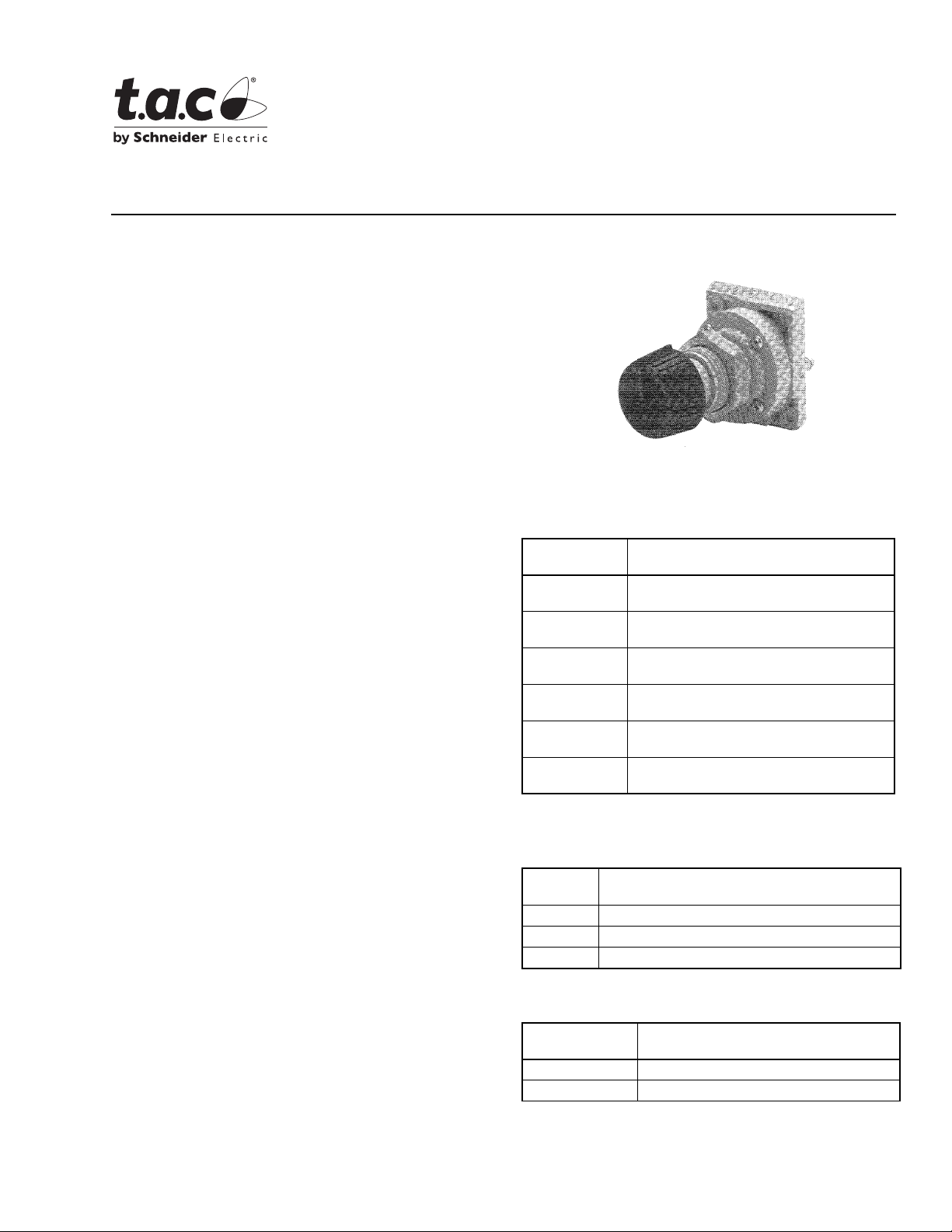
S520, S530, S540 Series
SK-520, SK-530, SK-540 Series
Two-, Three-, & Four-Position
Selector Switches
General Instructions
S5XX/SK-5XX shown without dial plate
Table-1 Specifications.
Model
Number
S520
SK-520
S521
SK-521
S530
SK-530
S531
SK-531
S540
SK-540
S541
SK-541
For Dial Plate Specifications, see page 2.
Table-2 Mounting Bracket Accessories.
Model
Number
K511 Single switch bracket
K512 One switch & one gauge per bracket
K514 Two switches & two gauges per bracket
Table-3 Replacement Parts.
Model
Number
K550 Replacement Knob
K551 Replacement Locknut
Description
2-Position - 4 branch
2-Position - 5 branch
(unused ports blocked)
3-Position - 4 branch
(unused ports blocked)
3-Position - 4 branch
(unused ports exhausted)
4-Position - 5 branch
(unused ports blocked)
4-Position - 5 branch
(unused ports exhausted)
Description
Description
Printed in U.S.A. 9-08 © Copyright 2008 TAC All Rights Reserved. F-23916-3
Page 2
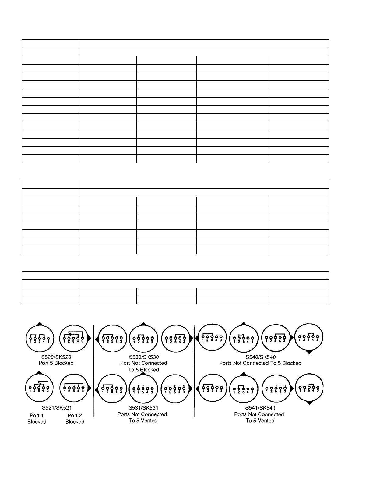
Table-4 Dial Plates for use with S520/SK-520 and S521/SK-521.
Model Number Dial Markings
50-06 Blank
50-09 Occup. Unoccup. — —
50-11 Min. Max. — —
50-13 Winter Summer — —
50-14 Manual Auto — —
50-15 Auto Off — —
50-16 On Auto — —
50-17 On Off — —
50-18 Closed Auto — —
50-19 Open Auto — —
50-20 Open Closed — —
50-23 Day Night — —
50-24 Heat Cool — —
50-52 1 2 — —
Table-5 Dial Plates for use with S530/SK-530 and S531/SK-531.
Model Number Dial Markings
50-06 Blank
50-32 1 2 3 —
50-37 Open Auto Closed —
50-38 Heat Auto Cool —
50-39 Day Auto Night —
50-45 Winter Auto Summer —
50-46 Occup. Auto Unoccup. —
50-47 On Auto Off —
Table-6 Dial Plates for use with S540/SK-540 and S541/SK-541.
Model Number Dial Markings
50-06 Blank
50-48 2 3 4 1
50-49 Heat Vent Cool Auto
Figure-1 Internal Port Connections.
2 © Copyright 2008 TAC All Rights Reserved. F-23916-3
Page 3

PRE-INSTALLATION
Inspection
Inspect the carton for damage. If damaged, notify the
appropriate carrier immediately. Inspect the device for
obvious damage due to shipping. Return damaged products.
Required Installation Items
• Piping diagrams
• Tools (not provided)
Appropriate screwdriver(s) for mounting screws
• Mounting screws (not provided)
• Appropriate accessories
INSTALLATION
Caution:
1. Installer must be a qualified, experienced technician.
2. Make all connections in accordance with the piping
diagram.
3. Do not locate the device in areas subjected to excessive
vibration or corrosive atmospheres.
4. Do not exceed ratings of the device.
Figure-2 Panel Cutout Dimensions.
Clean, Dry Oil Free Air Supplies for Pneumatic
Systems
Caution:
coalescing filter will provide clean, dry, oil free air required
(reference EN-123).
Compressor oil must be non-paraffin mineral base or
naphtha base. Synthetic or paraffin base oils will destroy
pneumatic controls and void the warranty.
A refrigerated air dryer, particulate filter and a
MOUNTING INSTRUCTIONS
Panel Mounting
Inside, These devices have been designed to be mounted on
a MCS-S-P manifold socket which is mounted to the
appropriate manifold backplate.
Surface, These devices may also be mounted on a panel face
(1/2" maximum panel thickness) by using a 1-1/64" mounting
hole, see Figure 2.
Field Mounting
These devices may also be mounted without the backplate,
socket and gasket by using the appropriate mounting bracket
as shown in Table 2 or PKG-1133 kit that includes plastic
mounting strap and adhesive mounting base.
Figure-3 Mounting Dimensions.
DIAL PLATE INSTALLATION
With the knob removed and the locknut run back for
clearance, turn the dial plate to fit over the projections on the
front of the switch body. Align and engage the vertical notch in
the dial plate with the tab behind the top switch body
projection. Tighten the locknut against the back of the dial and
replace knob, see Figure 5.
MAINTENANCE
Regular maintenance of the total system is needed to assure
sustained optimum performance.
REPAIR
No Field repair is possible. Replace selector switch with a
functioning unit.
F-23916-3 © Copyright 2008 TAC All Rights Reserved. 3
Page 4

Figure-4 K511, K512 & K514 Mounting Dimensions.
Figure-5 Dial Plate Installation.
Copyright 2008, TAC
All brand names, trad emarks and registered
trademarks are the property of their respective
owners. Information contained within this
document is subject to change without notice.
F-23916-3
Figure-6 Automatic or Manual Changeover of Day/Night System.
 Loading...