

Page 1
S1000/2000/3000
For Commercial HVAC Applications
Product ov
erview
Viconics' latest generation S1000/2000/3000 series sensors have been especially developed for the VT7600
programmable and non-programmable thermostats as well as future Viconics thermostats. These robust
sensors have provide accurate and stable temperature reading using a 10 Kohm thermistor element.
The S3000 series include all wall/room sensors, the S2000 series include all the duct/outdoor air models, and
the S1000 include in duct change over sensing and submersible water sensing . Temperature averaging
applications using only two or three S3000 sensors can easily be done by setting the dip switches to the
appropriate position. It is to be noted that temperature averaging with the usual 4, 9, 16, 25, etc sensors can
also be done, both with the S2000 and S3000 series. See table below for specific model numbers:
Models
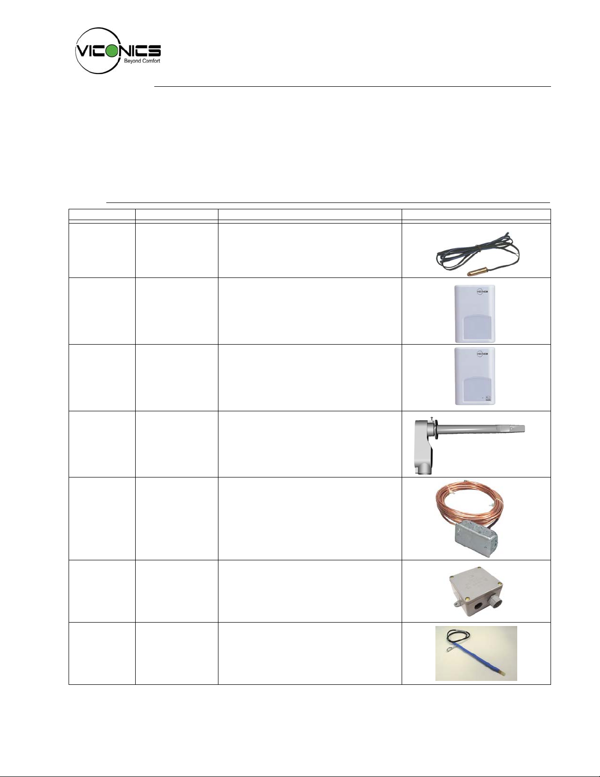
Model: Description: Application: Picture:
S1010E1000 Capsule type
sensor for multipurpose use, ¼”
dia. capsule with
65 inch leads
S3010W1000 Room sensor
S3020W1000 Room sensor with
temporary
override key and
occupancy LED
• Remote sensing easy to dissimulate for
indoor and outdoor use
• Water temperature sensing strapped on
pipe or in an immersion well
• Remote room sensing
• 3 thermistors with 2 dip switches are
provided with each sensor for various
averaging combinations
• Remote room sensing with override key
and occupancy LED
• 3 thermistors with 2 dip switches are
provided with each sensor for various
averaging combinations
S2000D1000
S2060A1000
S2020E1000
S1010D1000
Duct sensor with
junction box
Duct averaging
sensor, with 6 ft
sensor
Outside air
sensor, NEMA 4
enclosure
Duct Mounted
Change Over
Sensor
• Remote return air temperature sensing
with the sensor mounted on the return air
duct.
• Outside air temperature sensing with the
sensor installed in the fresh air plenum.
• Supply air temperature sensor
• Remote averaging discharge air
temperature sensing with the sensor
mounted on the supply air duct.
• Outside air temperature averaging
sensing with the sensor installed in the
fresh air plenum.
• Mixed air temperature averaging sensor
for economizer models with the sensor in
• Outside air temperature sensing with the
sensor installed directly exposed to the
elements.
• Sensor uses a water resistant NEMA 4
PVC enclosure for outdoor applications
• Change Over Duct Sensing
• Mounting: Through hole in duct, with
eyelet
028-0106
028-0106 INS-S2030-B02
Page 2
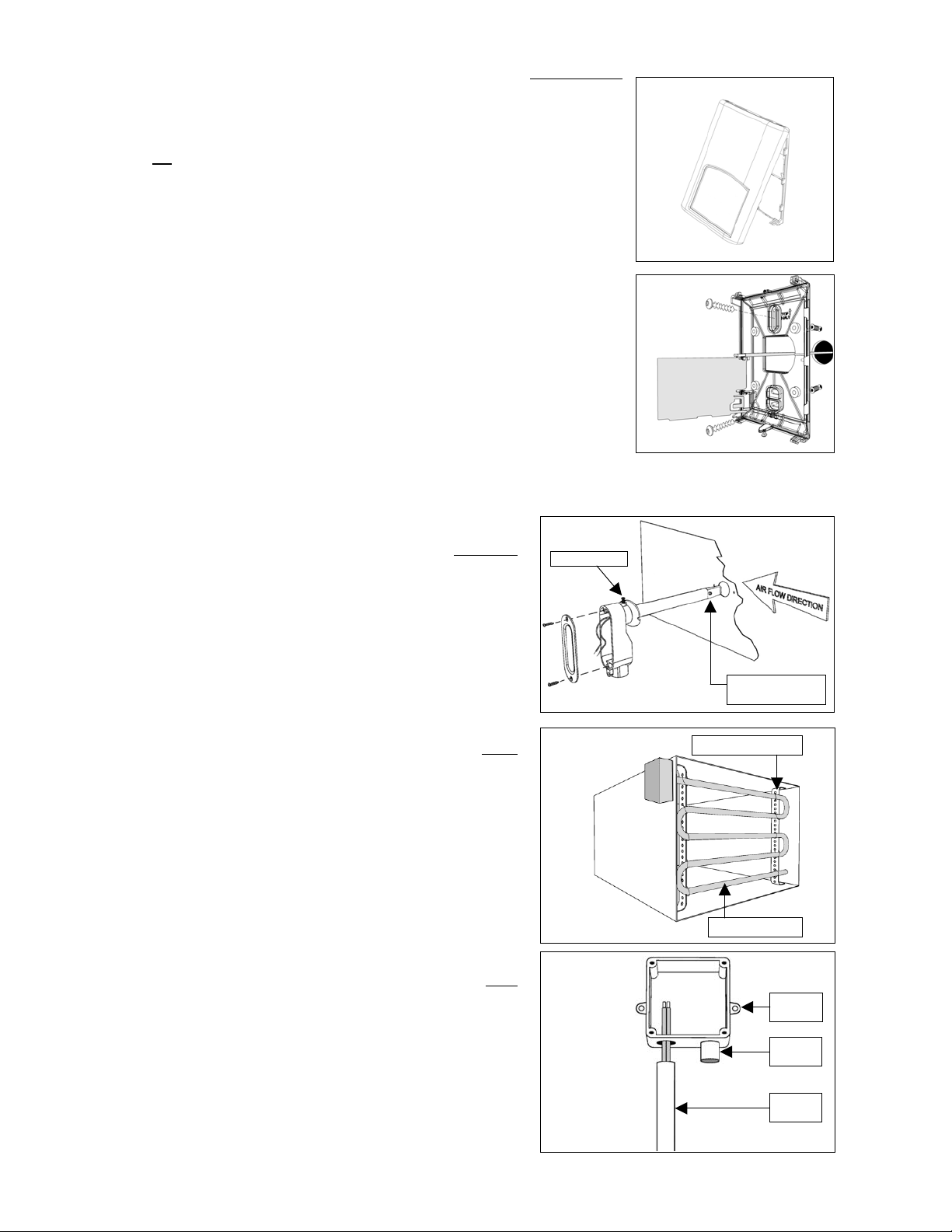
Installation of room sensors (S3010W1000 and S3020W1000)
p
• Remove security screw on the bottom of sensor cover.
• Open up by pulling on the bottom side of sensor. (Fig.1)
Location:
1- Should
2- Must be installed away from any heat source.
3- Should not be installed near an air discharge grill.
4- Should not be affected by direct sun radiation.
5- Nothing must restrain vertical air circulation to the sensor.
Installation:
1.
Remove security screw on the bottom of thermostat cover.
2. Open up by pulling on the bottom side of thermostat.
3. Pull out cables 6” out of the wall.
4. Wall surface must be flat and clean.
5. Insert cable in the central hole of the base.
6. Flip printed circuit board to access mounting hole
7. Align the base and mark the location of the two mounting holes on the wall. Install
proper side of base up.
8. Install anchors in the wall.
9. Insert screws in mounting holes on each side of the base. DO NOT
OVERTIGHTEN
10. Strip each wire 1/4 inch.
11. Insert each wire according to wiring diagram.
12. Gently push back into hole excess wring back into the wall.
13. Press back printed circuit board into place
14. Install the cover, top side
15. Install security screw.
not be installed on an outside wall.
Fig. 1
Fig. 2
2
Installation of duct sensors (S2000D1000) – (Fig.3)
1. Drill 1” [25mm] hole mid height on the side of the duct to insert the
probe.
2.
Loosen swivel screw and direct the probe so that the flat side of
probe tip is facing the airflow.
3. Mark the position of the two holes to be drilled for mounting the
sensor on the duct. Fasten the sensor to the duct with the two
screws provided. Do not overtighten!
4. Junction box must be directed downwards or sideways.
5. For best results, locate sensor as far as you can from
heating/cooling source.
Installation of averaging sensor (S2060A1000) - (Fig.4)
1. Drill 5/8” [16 mm] hole for the element to pass into the duct.
2. Run the sensing element into the duct.
3. Remove the cover from the unit.
4.
Mark the position of the holes to be drilled for mounting the case
on the duct.
5. Fasten the sensor element in an “S” shaped pattern in order to
cover the entire duct section area. Ensure that the probe does not
touch the duct.
6. Firmly support the element in the duct using perforated steel strap
and wire fastenings.
7. For best results, locate sensor as far as you can from
heating/cooling source.
Installation of outside air sensor (S2020E1000) – (Fig.5)
1. Install sensor using mounting holes on each side.
2. Install on a vertical surface, respect mounting orientation
3. Remove the four screws and remove the cover.
4. Strip each wire 1/4 inch.
5. Insert each wire according to wiring diagram.
6. Install the cover with supplied screws.
7. In snowy area allow sufficient height for snow accumulation.
Swivel screw
Fig.3
Fig.4
Fig.5
Probe tip, flat side
facing airflow
Perforated steel
Sensing element
Mounting
hole
Sensing
robe
EMT
conduit
Page 3

Wiring example of single remote room sensor:
r
p
VT7600 Series
Thermostat
Scom
RS
AU
C
D1
D2
1x 3020W1000
Wiring 1 sensor
S2-1 = ON / S2-2 = ON
ScomRSScom
RS
Aux
C
DI
OR
S3010W1000
Wiring 1 sensor
S2-1 = ON / S2-2 = ON
ScomRSScom
RS
Wiring examples of 2 remote room sensors for averaging applications:
VT7600
Series
Scom
RS
AU
C
D1
D2
2x S3020W1000
Wiring 2 sensors
S2-1 = OFF / S2-2 = ON
ScomRSScom
RS
Aux
C
DI
ScomRSScom
RS
Aux
C
DI
D2
VT7600
Series
Scom
RS
AU
C
D1
Dip switch
setting for:
1 senso
2x S3010W1000
Wiring 2 sensors
S2-1 = OFF / S2-2 = ON
ScomRSScom
RS
ScomRSScom
RS
ON
1
S2-1 = ON
S2-2 = ON
2
3
VT7600
Series
Scom
RS
AU
D1
D2
C
1x S3010W1000 and 1x S3020W1000
Wiring 2 sensors
ScomRSScom
RS
Notes for averaging applications:
• S3010W1000 and S3020W1000 can be mixed matched.
• S3010W
S2-1 = OFF / S2-2 = ON
ScomRSScom
RS
Aux
C
DI
• Res
1000 and S3020W1000 are to be wired in parallel.
ect the dip switch setting in each remote sensor.
Wiring examples of 3 remote room sensors for averaging applications:
VT7600
Series
Scom
RS
AU
D1
D2
C
2x S3010W1000 and 1x S3020W1000
Wiring 3 sensors
ScomRSScom
RS
ScomRSScom
RS
S2-1 = OFF / S2-2 = OFF
ScomRSScom
RS
Aux
C
DI
VT7600 Series
Thermostat
Scom
RS
AU
C
D1
D2
1x S3010W1000 and 2x S3020W1000
Wiring 3 sensors
S2-1 = OFF / S2-2 = OFF
ScomRSScom
Temperature vs resistance chart for 10 kOhm NTC thermistor
(R
= 10KΩ±3% - B
25°C
ºC ºF kohms ºC ºF kohms ºC ºF kohms ºC ºF kohms ºC ºF kohms
-20 -4 94.5149 -10 14 54.1988 0 32 32.1910 10 50 19.7390 20 68 12.4601
-19 -2 89.2521 -9 16 51.3692 1 34 30.6120 11 52 18.8277 21 70 11.9177
-18 0 84.3147 -8 18 48.7042 2 36 29.1167 12 54 17.9636 22 72 11.4018
-17 1 79.6808 -7 19 46.1933 3 37 27.7088 13 55 17.1440 23 73 10.9112
-16 3 75.3299 -6 21 43.8268 4 39 26.3744 14 57 16.3665 24 75 10.4443
-15 5 71.2430 -5 23 41.5956 5 41 25.1119 15 59 15.6286 25 77 10.0000
-14 7 67.4028 -4 25 39.4912 6 43 23.9172 16 61 14.9280 26 79 9.5754
-13 9 63.7928 -3 27 37.5056 7 45 22.7861 17 63 14.2629 27 81 9.1711
-12 10 60.3980 -2 28 35.6316 8 46 21.7151 18 64 13.6310 28 82 8.7860
-11 12 57.2044 -1 30 33.8622 9 48 20.7004 19 66 13.0307 29 84 8.4190
= 3975K±1.5%)
25/85°C
RS
Aux
C
DI
ScomRSScom
RS
Aux
C
DI
Dip switch
setting for:
2 sensors
ScomRSScom
Dip switch
setting for:
3 sensors
Fig.6
ON
S2-1 = OFF
S2-2 = ON
2
1
RS
ON
S2-1 = OFF
-
=
2
1
ON
12
Wall mounted sensor
Dip switch location
WIRING S2000D1000, S2060A1000 and S2020E1000
Remote wiring 1 sensor Remote wiring 4 sensors
10 K
10 K
10 K
10 K
10 K
VT7600 Series thermostat VT7600 Series thermostat
RS
ScomMSScom
or
or
OS
Scom
RS
Scom
or
MS
Scom
or
OS
Scom
Page 4

Specifications:
F
0
General for all sensors
4
Fig.7
Sensor ty
pe: 10 K ohm NTC thermistor
Maximum wire length: 5,000 feet [1,525 m]
for 24 GA wire and up
Room sensors (S3010W1000 and S3020W1000)
Operating conditions:
0 °C to 50 °C ( 32 °F to 122 °F )
0% to 95% R.H. non-condensing
Storage conditions:
-30 °C to 50 °C ( -22 °F to 122 °
0% to 95% R.H. non-condensing
Dimensions:
4.94” [125 mm] high
3.38” [86 mm] wide
1.13” [29 mm] thick
Approximate shipping
weight: 0.34 LBS (155 grams )
Enclosure plastic type ABS - FRI [WT1337V] UV stabilized
Duct sensor (S2000D1000)
Operating conditions:
-40 °C to 50 °C ( -40 °F to 122 °
0% to 95% R.H. non-condensing
Storage conditions:
-40 °C to 70 °C ( -40 °F to 122 °
0% to 95% R.H. non-condensing
Dimensions:
(refer to draw
ing Fig.8)
Approximate shipping
w
eight: 0.7 LBS [0.3 Kg]
Probe tip plastic type: Fire retarding grade "HB" ABS
Averaging sensor (S2060A1000)
F )
F )
F )
ig.8
Fig.9
1.75" [44 mm]
4.40" [112 mm]
1.30" [33 mm]
4.25" [108 mm]
3.38" [86 mm]
2.25" [57 mm]
4.94" [125 mm]
1.13" [29 mm]
7.00" [178 mm]
1/2" [13 mm] FPT
c/c 1.75" [44mm]
Ø 5/32" [4 mm]
2.10" [53 mm]
Ø 0.75" [19 mm]
72" [1829 mm]
Ø 3/16" [5 mm]
Operating conditions:
-40 °C to 50 °C ( -40 °F to 122 °
0% to 95% R.H. non-condensing
Storage conditions:
-40 °C to 70 °C ( -40 °F to 158 °
0% to 95% R.H. non-condensing
Sensing element length
72 in [1,83 m]
Sensing element diameter /
material:
Dimensions:
3/16” [5 mm] / copper tube
(refer to drawing Fig.9)
Approximate shipping
weight: 1.6 LBS [0.7 Kg]
Outside air sensor (S2020E1000)
Operating and storage
conditions:
Dimensions:
-40 °C to 50 °C ( -40 °F to 122 °
0% to 100% R.H.
(refer to draw
ing Fig.10)
Approximate shipping
w
eight: 1.1 LBS [0.5 Kg]
Enclosure plastic type: NEMA 4 PVC
Duct Mounted Temperature Sensor (S1010D1000)
Operating conditions:
Sensing Bulb Type:
Up
to 85ºC [185ºF]
Plastic Heatshrink
Dimensions: (refer to drawing Fig.11)
Probe length / Diameter:
Wire Length:
12” [305 mm]
4-1/2” [114 mm]/
1/4” [6 mm]
F )
F )
F )
Fig. 1
c/c
Fig. 11
UNIT: INCH [mm] / NTS
4.00" [102 mm]
3.45" [88 mm]
3.45"
[88 m m ]
4.88" [124 mm]
1.19" [30 mm] 1.19" [30 mm]
1
[6]
4
FRONT VIEW
13
[20]
16
EYELET FOR MAX.Ø
3.67" [93 mm]
Ø 0.25"
[6 mm ]
Ø 8-32*
* Threa d e d
bras s i n s ert
c/c 4.68" [119 mm]
5.25" [133 mm]
3
4
[111 ]
8
DATE: 2002/04/19 - REV.0
[42 mm]
1.75"
[45 mm]
1.63"
Ø 7/8"
[22 m m ]
WIRE 12 [30 4 ]
3
[Ø5 ] S E LF-DRIL L ING SC R EW
16
DRAWN BY: P. DUMAS
0.25" [6 m m ]
2.125"
[54 m m ]
2.00"
[51 m m ]
7
[22]
8
4.00"
[102 m m ]
DWG N o.: 022-0114.dwg
1
[6]
4
Important notice
All
S1000, S2000 and S3000 series sensors are for use as operating controls only and are not safety devices. These instruments
have undergone rigorous tests and verifications prior to shipment to ensure proper and reliable operation in the field. Whenever a
control failure could lead to personal injury and/or loss of property, it becomes the responsibility of the user / installer / electrical
system designer to incorporate safety devices ( such as relays, flow switch, thermal protections, etc…) and/or alarm system to
protect the entire system against such catastrophic failures. Tampering of the devices or miss application of the device will void
warranty.
 Loading...