

Page 1

Page 2
Page 3

Page 4

Sensors Field Devices
TEMPERATURE INPUT TROUBLESHOOTING
1. Disconnect the wiring to the input and connect an ohm meter directly across the input wires at the
controller. Verify the measurement against the resistance to temperature chart found below.
2. Measure the resistance directly at the probe. If there is a significant difference between the resistance
measured at the probe and at the controller, then there is a resistance problem in the wiring, which will
affect the reading.
Note: When the controller no longer considers an input reading to be valid, it sets the ElecValue to
999.9. Each controller has two additional internal inputs. One is hard-wired to the reference
channel and the other is connected to ground. These two inputs are used for continuous software
calibration of the input circuit. If at any time either of these two inputs reads out of a predened
range, then the input routine will set the ElecValue of all inputs to 999.9.
Also note that if the override button is pushed during the measurement or is somehow shorted,
the resistance value read will be lower than the reading shown on the chart for the maximum
temperature (150 °F (65.5 °C) degrees).
Table-1. Resistance versus Temperature for Infinity Sensor
R Ohms °F (°C) R Ohms °F (°C) R Ohms °F (°C) R Ohms °F (°C)
29481.1 32 (0.0) 18331.5 51 (10.6) 11716.6 70 (21.1) 7680.64 89 (31.7)
28732.2 33 (0.6) 17892.8 52 (11.1) 11452.0 71 (21.7) 7516.78 90 (32.2)
28004.6 34 (1.1) 17465.9 53 (11.7) 11194.2 72 (22.2) 7356.9 91 (32.8)
27297.7 35 (1.7) 17050.4 54 (12.2) 10943.0 73 (22.8) 7200.88 92 (33.3)
26610.8 36 (2.2) 16646.1 55 (12.8) 10698.1 74 (23.3) 7048.62 93 (33.9)
25943.4 37 (2.8) 16252.6 56 (13.3) 10459.4 75 (23.9) 6900.01 94 (34.4)
25294.7 38 (3.3) 15869.6 57 (13.9) 10226.8 76 (24.4) 6754.96 95 (35.0)
24664.2 39 (3.9) 15496.8 58 (14.4) 10000.0 77 (25.0) 6613.38 96 (35.6)
24051.4 40 (4.4) 15133.8 59 (15.0) 9778.91 78 (25.6) 6475.18 97 (36.1)
23455.6 41 (5.0) 14780.4 60 (15.6) 9563.35 79 (26.1) 6340.25 98 (36.7)
22876.5 42 (5.6) 14436.4 61 (16.1) 9353.18 80 (26.7) 6208.53 99 (37.2)
22313.4 43 (6.1) 14101.3 62 (16.7) 9148.24 81 (27.2) 6079.91 100 (37.8)
21765.9 44 (6.7) 13775.1 63 (17.2) 8948.38 82 (27.8) 5954.33 101 (38.3)
21233.5 45 (7.2) 13457.3 64 (17.8) 8753.48 83 (28.3) 5831.7 102 (38.9)
20715.7 46 (7.8) 13147.9 65 (18.3) 8563.39 84 (28.9) 5711.95 103 (39.4)
20212.2 47 (8.3) 12846.4 66 (18.9) 8377.98 85 (29.4) 5594.99 104 (40.0)
19722.4 48 (8.9) 12552.8 67 (19.4) 8197.12 86 (30.0) 5480.76 105 (40.6)
19245.9 49 (9.4) 12266.8 68 (20.0) 8020.69 87 (30.6) — —
18782.4 50 (10.0) 11988.1 69 (20.6) 7848.56 88 (31.1) — —
44
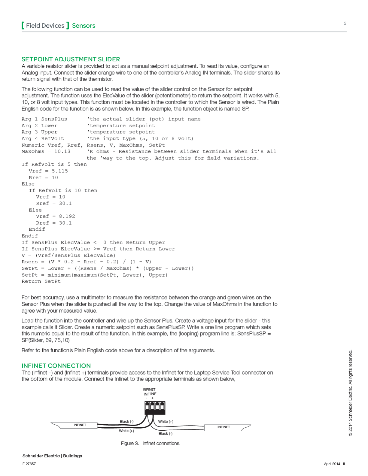
LAPTOP SERVICE TOOL CONNECTION
The connector located on the bottom of the sensor provides access to the Infinet for the Laptop Service Tool.
Connect the Laptop Service Tool cable as shown below.
Figure 6. Service connector on the bottom of the sensor.
All brand names and registered trademarks are the property of their respective owners. Information contained within this document is subject to change
without notice. All rights reserved.
Schneider Electric | Buildings
F-27857 April 2014 tl
© 2014 Schneider Electric. All rights reserved.
 Loading...