

Harmony XB5R
EIO0000000812 01/2014
Harmony XB5R
Expert Instruction Sheet
01/2014
www.schneider-electric.com
EIO0000000812.03

The information provided in this documentation contains general descriptions and/or technical
characteristics of the performance of the products contained herein. This documentation is not
intended as a substitute for and is not to be used for determining suitability or reliability of these
products for specific user applications. It is the duty of any such user or integrator to perform the
appropriate and complete risk analysis, evaluation and testing of the products with respect to the
relevant specific application or use thereof. Neither Schneider Electric nor any of its affiliates or
subsidiaries shall be responsible or liable for misuse of the information contained herein. If you
have any suggestions for improvements or amendments or have found errors in this publication,
please notify us.
No part of this document may be reproduced in any form or by any means, electronic or
mechanical, including photocopying, without express written permission of Schneider Electric.
All pertinent state, regional, and local safety regulations must be observed when installing and
using this product. For reasons of safety and to help ensure compliance with documented system
data, only the manufacturer should perform repairs to components.
When devices are used for applications with technical safety requirements, the relevant
instructions must be followed.
Failure to use Schneider Electric software or approved software with our hardware products may
result in injury, harm, or improper operating results.
Failure to observe this information can result in injury or equipment damage.
© 2014 Schneider Electric. All rights reserved.
2 EIO0000000812 01/2014

Table of Contents
Safety Information . . . . . . . . . . . . . . . . . . . . . . . . . . . . . 5
About the Book. . . . . . . . . . . . . . . . . . . . . . . . . . . . . . . . 7
Chapter 1 Harmony XB5R Introduction . . . . . . . . . . . . . . . . . . . . . 9
General Presentation of Harmony XB5R . . . . . . . . . . . . . . . . . . . . . .
Presentation of Harmony XB5R Ready to Use Packages. . . . . . . . . .
Presentation of XB5R Components. . . . . . . . . . . . . . . . . . . . . . . . . . .
Chapter 2 Installation. . . . . . . . . . . . . . . . . . . . . . . . . . . . . . . . . . . . 23
General Installation Instruction for Harmony XB5R . . . . . . . . . . . . . .
Transmitter and Pushbutton Assembly . . . . . . . . . . . . . . . . . . . . . . . .
Transmitter and Pushbutton Disassembly. . . . . . . . . . . . . . . . . . . . . .
Mounting Data for Rope Pull Switch . . . . . . . . . . . . . . . . . . . . . . . . . .
Mounting Instructions for ZBRM01 Handy Box . . . . . . . . . . . . . . . . . .
Mounting Instructions for ZBRM21/ZBRM22 Mobile Boxes . . . . . . . .
Mounting instructions For ZBRACS Support. . . . . . . . . . . . . . . . . . . .
Receiver Assembly and Disassembly . . . . . . . . . . . . . . . . . . . . . . . . .
Receiver Wiring Diagram. . . . . . . . . . . . . . . . . . . . . . . . . . . . . . . . . . .
Relay Antenna Installation. . . . . . . . . . . . . . . . . . . . . . . . . . . . . . . . . .
Chapter 3 Preparing For Use . . . . . . . . . . . . . . . . . . . . . . . . . . . . . 51
Compatability Rules. . . . . . . . . . . . . . . . . . . . . . . . . . . . . . . . . . . . . . .
Transmitter Types . . . . . . . . . . . . . . . . . . . . . . . . . . . . . . . . . . . . . . . .
LED Status . . . . . . . . . . . . . . . . . . . . . . . . . . . . . . . . . . . . . . . . . . . . .
Output mode: Monostable - Bistable - Stop/Start - Set/Reset . . . . . . .
Changing outputs from Monostable to Bistable for XB•RFA02,
XB5RMA04, ZBRRA, and ZBRRD . . . . . . . . . . . . . . . . . . . . . . . . . . .
Changing Outputs From Monostable to Stop/Start for XB•RFA02,
XB5RMA04, ZBRRA . . . . . . . . . . . . . . . . . . . . . . . . . . . . . . . . . . . . . .
How to Teach/Unteach Monostable, Bistable or Set/Reset Outputs for
XB•RFA02, XB5RMA04, ZBRRA, ZBRRC, and ZBRRD. . . . . . . . . . .
How to Teach Stop/Start Outputs for XB•RFA02, XB5RMA04, ZBRRA
Lock/Unlock for XB•RFA02, XB5RMA04, ZBRRA, ZBRRC, and
ZBRRD . . . . . . . . . . . . . . . . . . . . . . . . . . . . . . . . . . . . . . . . . . . . . . . .
Chapter 4 Other Functions for Harmony XB5R. . . . . . . . . . . . . . . 71
Other Functions Description . . . . . . . . . . . . . . . . . . . . . . . . . . . . . . . .
10
12
14
24
28
33
35
36
38
40
41
44
46
52
53
54
56
59
61
63
65
68
71
EIO0000000812 01/2014 3

Chapter 5 Harmony XB5R ATEX Products . . . . . . . . . . . . . . . . . . 75
5.1 Transmission Products. . . . . . . . . . . . . . . . . . . . . . . . . . . . . . . . . . . . .
Presentation of ATEX Transmission Components. . . . . . . . . . . . . . . .
ID Registration . . . . . . . . . . . . . . . . . . . . . . . . . . . . . . . . . . . . . . . . . . .
Assembly, Disassembly, and Mounting Instructions . . . . . . . . . . . . . .
XAWGR•••EX Mounting Instructions . . . . . . . . . . . . . . . . . . . . . . . . . .
5.2 Reception Products . . . . . . . . . . . . . . . . . . . . . . . . . . . . . . . . . . . . . . .
Presentation of ATEX Reception Components . . . . . . . . . . . . . . . . . .
ZBRA1DEX Mounting and Wiring Instructions. . . . . . . . . . . . . . . . . . .
ZBRA1EX Mounting and Wiring Instructions . . . . . . . . . . . . . . . . . . . .
5.3 Functions . . . . . . . . . . . . . . . . . . . . . . . . . . . . . . . . . . . . . . . . . . . . . . .
Functions of ATEX Components . . . . . . . . . . . . . . . . . . . . . . . . . . . . .
76
77
79
81
82
84
85
87
89
91
91
4 EIO0000000812 01/2014
Safety Information
Important Information
NOTICE
Read these instructions carefully, and look at the equipment to become familiar with the device
before trying to install, operate, or maintain it. The following special messages may appear
throughout this documentation or on the equipment to warn of potential hazards or to call attention
to information that clarifies or simplifies a procedure.
EIO0000000812 01/2014 5

PLEASE NOTE
Electrical equipment should be installed, operated, serviced, and maintained only by qualified
personnel. No responsibility is assumed by Schneider Electric for any consequences arising out of
the use of this material.
A qualified person is one who has skills and knowledge related to the construction and operation
of electrical equipment and its installation, and has received safety training to recognize and avoid
the hazards involved.
6 EIO0000000812 01/2014

About the Book
At a Glance
Document Scope
This documentation is a reference for the Harmony XB5R wireless and batteryless pushbutton.
Validity Note
This documentation is valid for Harmony XB5R.
The technical characteristics of the devices described in this manual also appear online. To access
this information online:
Step Action
1 Go to the Schneider Electric home page www.schneider-electric.com.
2 In the Search box type the reference of a product or the name of a product
3 If you entered a reference, go to the Product datasheets search results and
4 If more than one reference appears in the Products search results, click on the
5 Depending on the size of your screen, you maybe need to scroll down to see the
6 To save or print a data sheet as a .pdf file, click Download XXX product
range.
Do not include blank spaces in the model number/product range.
To get information on a grouping similar modules, use asterisks (*).
click on the reference that interests you.
If you entered the name of a product range, go to the Product Ranges search
results and click on the product range that interests you.
reference that interests you.
data sheet.
datasheet.
The characteristics that are presented in this manual should be the same as those characteristics
that appear online. In line with our policy of constant improvement, we may revise content over time
to improve clarity and accuracy. If you see a difference between the manual and online information,
use the online information as your reference.
EIO0000000812 01/2014 7
Related Documents
Title of Documentation Reference Number
Wireless and Batteryless Pushbutton Catalogue Module 36174
Package Instruction Sheet S1A57199
Receivers Instruction Sheet S1A57202
Transmitter with Metal or Plastic Head and Cap Instruction Sheet S1A57198
Relay Antenna Instruction Sheet S1A57194
Mobile Box Instruction Sheet S1A57210
ATEX Transmission Devices Instruction Sheet HRB29193
ATEX Reception Devices Instruction Sheet HRB41321
Rope Pull Switch Instruction Sheet S1B90581
You can download these technical publications and other technical information from our website
at www.schneider-electric.com.
Product Related Information
The application of this product requires expertise in the design and programming of control
systems.
UNINTENDED EQUIPMENT OPERATION
Only persons with expertise in the design and programming of control systems are allowed to
program, install, alter, and apply this product.
Follow all local and national safety codes and standards.
Failure to follow these instructions can result in death, serious injury, or equipment
damage.
WARNING
8 EIO0000000812 01/2014

Harmony XB5R
XB5R
EIO0000000812 01/2014
Harmony XB5R Introduction
Chapter 1
Harmony XB5R Introduction
Purpose
This chapter provides an overview of the Harmony XB5R.
What Is in This Chapter?
This chapter contains the following topics:
General Presentation of Harmony XB5R 10
Presentation of Harmony XB5R Ready to Use Packages 12
Presentation of XB5R Components 14
Topic Page
EIO0000000812 01/2014 9

XB5R
General Presentation of Harmony XB5R
Offer Presentation
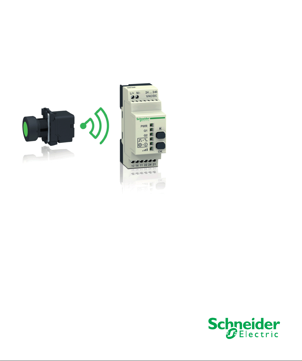
Harmony wireless and batteryless pushbuttons are used for remote control of a receiver relay
using a transmitter pushbutton. Control is via radio transmission: the transmitter is equipped with
a “dynamo” generator that converts the mechanical energy produced by pressing the pushbutton
into electrical energy. A radio-coded message with a unique ID code is sent, in a single pulse, to
one or more receiver(s) located several tens of metres away (see figure A). One receiver can also
be activated by different transmitters (see figure B).
This technology cannot be used for hoisting applications (“raise/lower”, “left/right”, etc.
movements) or safety applications (emergency stop buttons etc.). The Harmony XB4 and XB5
wired pushbutton range or the XAC pendant control station range have to be used for these
applications.
WARNING
UNINTENDED EQUIPMENT OPERATION
Do not use this equipment in safety critical machine functions.
Use appropriate safety interlocks where personnel and/or equipment hazards exist.
Do not disassemble, repair, or modify this equipment.
Install and operate this equipment in an appropriately rated enclosure for its intended
environment.
Install properly rated fuses.
Check that the control is not actived if the product falls during transit.
Failure to follow these instructions can result in death, serious injury, or equipment
damage.
10
NOTE: The rated fuses are indicated in the Receiver Wiring Diagram (see page 44).
EIO0000000812 01/2014
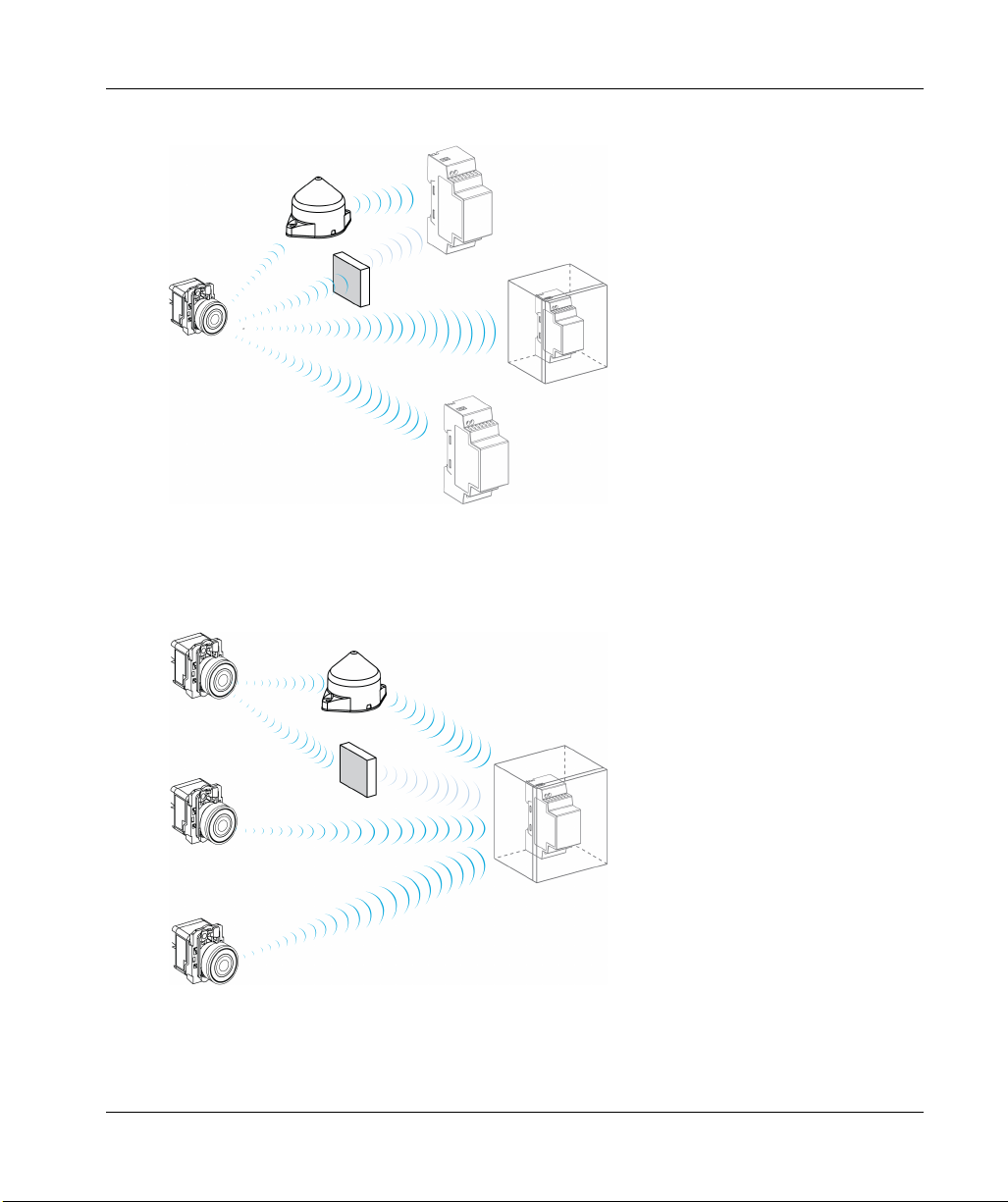
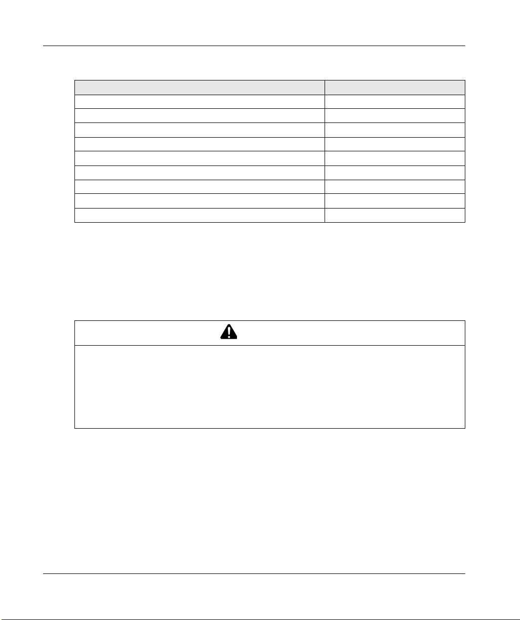
Figure A: Transmission between 1 Transmitter and 3 Receivers
NOTE: One transmitter can be taught and can activate several receivers. The number of receivers
is not limited.
Figure B: Transmission between 3 Transmitters and 1 Receiver
XB5R
NOTE: One receiver can be activated by several transmitters. The number of transmitters is
limited: 32 transmitters maximum.
EIO0000000812 01/2014 11
XB5R
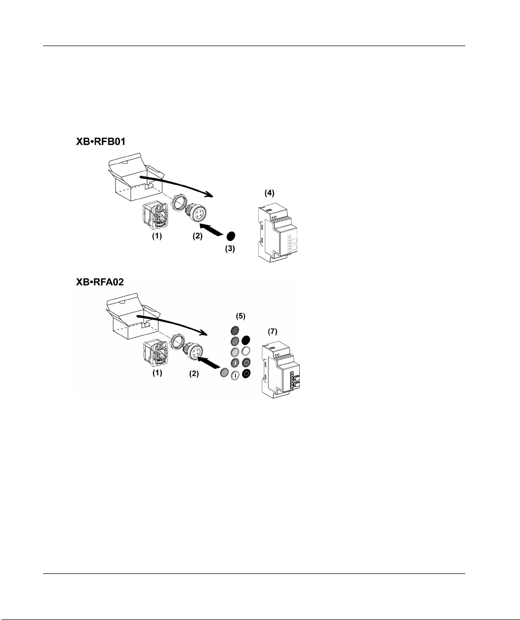
Presentation of Harmony XB5R Ready to Use Packages
Illustration
NOTE: The following figures show for all packages, the transmitter and the receiver are already
paired in Schneider factory.
12
EIO0000000812 01/2014

XB5R
1 Transmitter
2 Head
3 Cap
4 Non-programmable receiver
5 Set of 10 caps
6 Transmitter + Head + Mobile box
7 Programmable receiver
8 Magnet (could be glued on the box if needed)
DANGER
HAZARD OF ELECTRIC SHOCK, EXPLOSION OR ARC FLASH
• Disconnect all power before servicing equipment.
• Use only the specified voltage when operating this equipment and any associated products.
Failure to follow these instructions will result in death or serious injury.
EIO0000000812 01/2014 13

XB5R
Presentation of XB5R Components
Transmitters
14
EIO0000000812 01/2014
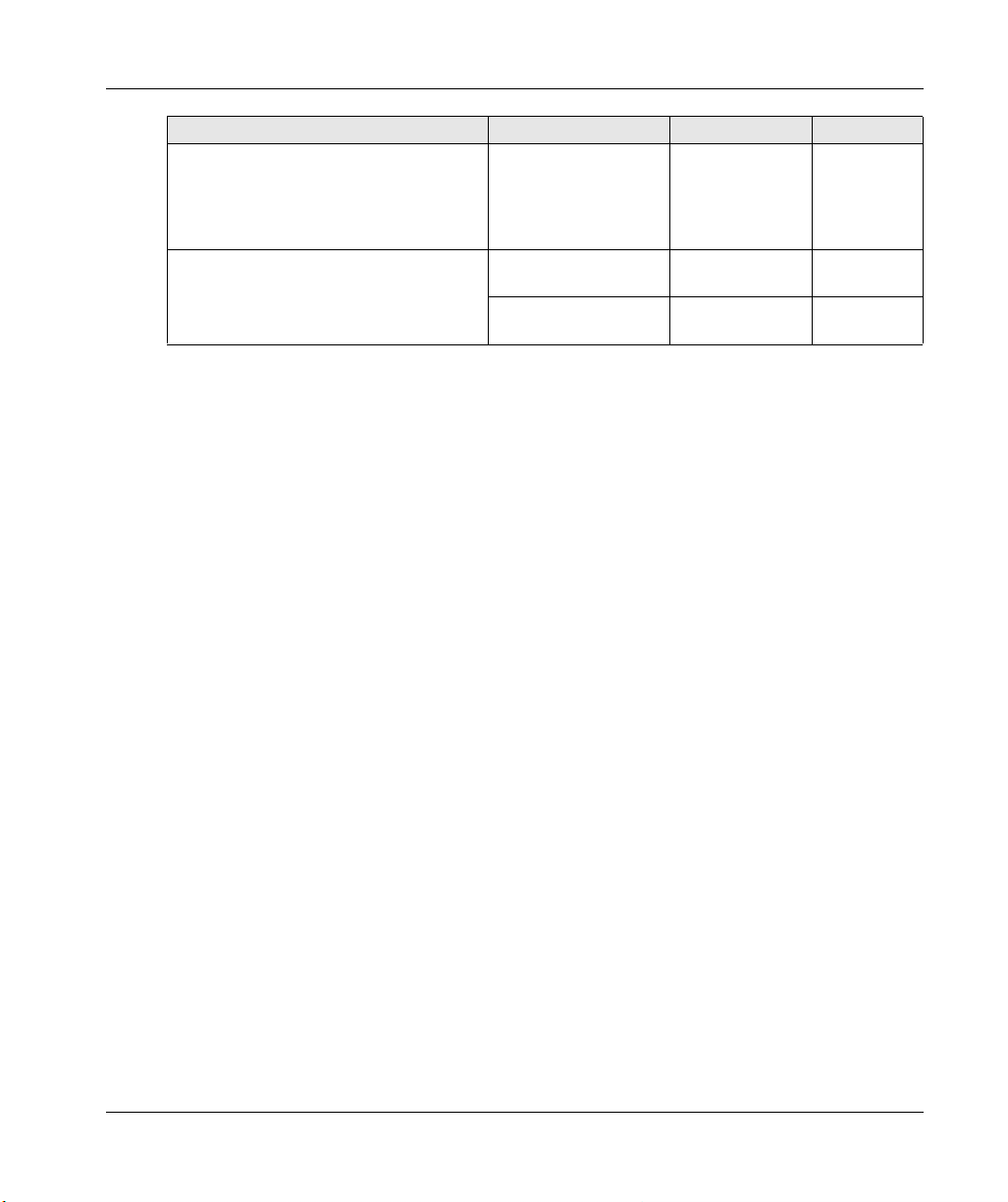
The following table describes the transmitter characteristics.
XB5R
Designation Pushbutton
Cap Color Reference Mass
Type
Transmitter Only (1 frame sent at the push of the
button)
Transmitter Only (1 frame sent at the push of the
button, 1 frame sent at the release of the button)
–– ZBRT10.025kg
(0.055 lb)
–– ZBRT20.025kg
(0.055 lb)
Spring return pushbutton heads for transmitter ZBRT1 Plastic Without cap ZB5RZA0 0.015 kg
(0.033 lb)
Metallic Without cap ZB4RZA0 0.030 kg
(0.066 lb)
EIO0000000812 01/2014 15

XB5R
Designation Pushbutton
Cap Color Reference Mass
Type
Pushbuttons including:
a ZBRT1 transmitter fitted with fixing collar
a spring return pushbutton head with clipped-in cap
Plastic White ZB5RTA1 0.045 kg
(0.099 lb)
Black ZB5RTA2 0.045 kg
(0.099 lb)
Green ZB5RTA3 0.045 kg
(0.099 lb)
“I” white on green
background
ZB5RTA331 0.045 kg
(0.099 lb)
Red ZB5RTA4 0.045 kg
(0.099 lb)
“O” White on red
background
ZB5RTA432 0.045 kg
(0.099 lb)
Yellow ZB5RTA5 0.045 kg
(0.099 lb)
Blue ZB5RTA6 0.045 kg
(0.099 lb)
Metallic White ZB4RTA1 0.085 kg
(0.187 lb)
Black ZB4RTA2 0.085 kg
(0.187 lb)
Green ZB4RTA3 0.085 kg
(0.187 lb)
“I” White on green
background
ZB4RTA331 0.085 kg
(0.187 lb)
Red ZB4RTA4 0.085 kg
(0.187 lb)
“O” White on red
background
ZB4RTA432 0.085 kg
(0.187 lb)
Yellow ZB4RTA5 0.085 kg
(0.187 lb)
Blue ZB4RTA6 0.085 kg
(0.187 lb)
Spring return mushroom head for ZBRT1/ZBRT2
transmitters
Pushbutton including:
a ZBRT1 transmitter fitted with fixing collar
a spring return mushroom head
Plastic Black ZB5RZC2 0.025 kg
(0.055 lb)
Plastic Black ZB5RTC2 0.055 kg
(0.121 lb)
Rope Pull Switch Plastic Black ZBRP1 0.150 kg
(0.331 lb)
16
EIO0000000812 01/2014
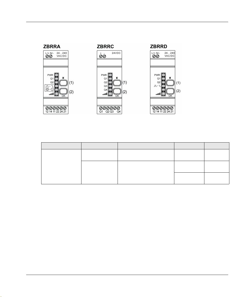
Programmable Receivers
The following figure shows the programmable receivers.
(1): Selection button
(2): Validation button
The following table describes the characteristics of programmable receivers.
Designation Ouputs Receiver Voltage Reference Mass
Programmable
Receivers with
indicator light LED
and teach button
4 PNP
200 mA
2 relays change
over 3 A
XB5R
24 Vdc ZBRRC 0.130 kg
(0.287 lb)
24...240 Vac/Vdc ZBRRA 0.130 kg
(0.287 lb)
ZBRRD 0.130 kg
(0.287 lb)
EIO0000000812 01/2014 17

XB5R
Harmony ZB5RZA0 and ZB4RZA0 Pushbutton Caps
The following table describes the characteristics of the caps for the ZB5RZA0 and ZB4RZA0
pushbuttons.
Cap Color Labeling Reference Mass
White - ZBA71 0.010 kg
“I” black ZBA7137 0.010 kg
“↑ ” black ZBA7134 0.010 kg
“+” black ZBA7138 0.010 kg
Black - ZBA72 0.010 kg
“O” white ZBA7232 0.010 kg
“+” white ZBA7233 0.010 kg
“↓” white ZBA7235 0.010 kg
“I” white ZBA7237 0.010 kg
(0.022 lb)
(0.022 lb)
(0.022 lb)
(0.022 lb)
(0.022 lb)
(0.022 lb)
(0.022 lb)
(0.022 lb)
(0.022 lb)
18
EIO0000000812 01/2014

Cap Color Labeling Reference Mass
Green - ZBA73 0.010 kg
(0.022 lb)
“I” white ZBA7331 0.010 kg
(0.022 lb)
“+” white ZBA7333 0.010 kg
(0.022 lb)
“↑ ” white ZBA7335 0.010 kg
(0.022 lb)
“II” white ZBA7336 0.010 kg
(0.022 lb)
Red - ZBA74 0.010 kg
(0.022 lb)
“O” white ZBA7432 0.010 kg
(0.022 lb)
Yellow - ZBA75 0.010 kg
(0.022 lb)
Blue - ZBA76 0.010 kg
(0.022 lb)
XB5R
EIO0000000812 01/2014 19
XB5R
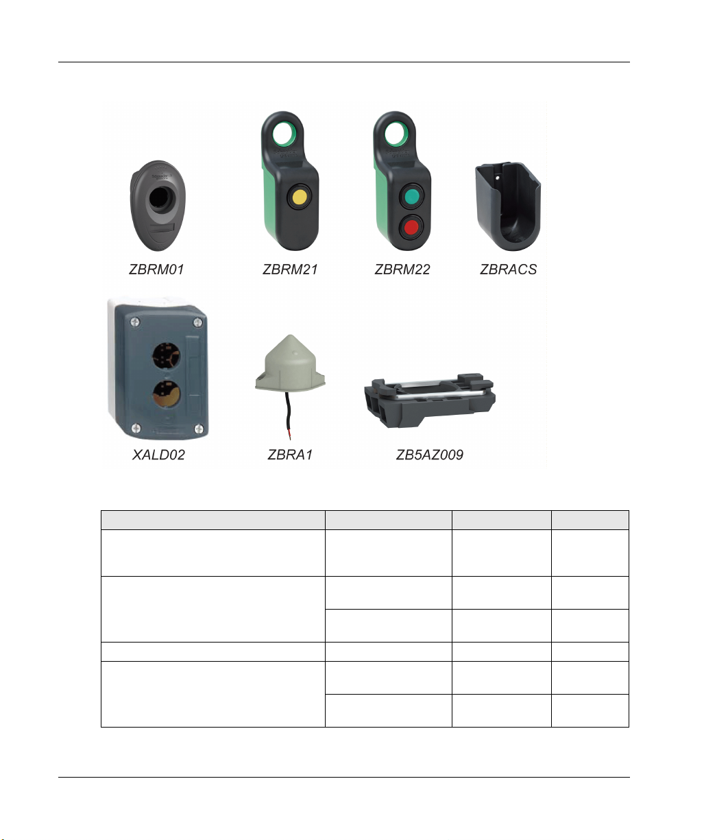
Accessories
20
The following table describes the characteristics of housing and accessories for XB5R.
Designation Description Reference Mass
Empty plastic handy box for mobile
applications with wireless and batteryless
pushbutton
Empty plastic mobile box for mobile and fixed
applications with wireless and batteryless
pushbutton
Support for ZBRM21/ZBRM22 Plastic – ZBRACS 0.064 kg
Empty plastic box for embedded or fixed
transmitter
1 hole ZBRM01 0.09 kg
(1.984 lb)
1 hole ZBRM21 0.109 kg
(0.240 lb)
2 holes ZBRM22 0.110 kg
(0.242 lb)
1 hole XALD01 0.136 kg
(0.299 lb)
2 holes XALD02 0.193 kg
(0.425 lb)
EIO0000000812 01/2014
Designation Description Reference Mass
Relay-Antenna for increased distances 24...240 Vac/Vdc
- Cable(5m/16.4ft)
ZBRA1 0.200 kg
(0.440 lb)
- 1 Voltage LED
- 2 Reception/Emission
LED
Mounting Base Plastic ZB5AZ009 0.006 kg
(0.013 lb)
Metallic ZB4BZ009 0.038 kg
(0.083 lb)
XB5R
EIO0000000812 01/2014 21

XB5R
22
EIO0000000812 01/2014

Harmony XB5R
XB5R
EIO0000000812 01/2014
Installation
Chapter 2
Installation
Purpose
This chapter provides an overview of the Harmony XB5R installation.
What Is in This Chapter?
This chapter contains the following topics:
General Installation Instruction for Harmony XB5R 24
Transmitter and Pushbutton Assembly 28
Transmitter and Pushbutton Disassembly 33
Mounting Data for Rope Pull Switch 35
Mounting Instructions for ZBRM01 Handy Box 36
Mounting Instructions for ZBRM21/ZBRM22 Mobile Boxes 38
Mounting instructions For ZBRACS Support 40
Receiver Assembly and Disassembly 41
Receiver Wiring Diagram 44
Relay Antenna Installation 46
Topic Page
EIO0000000812 01/2014 23
XB5R
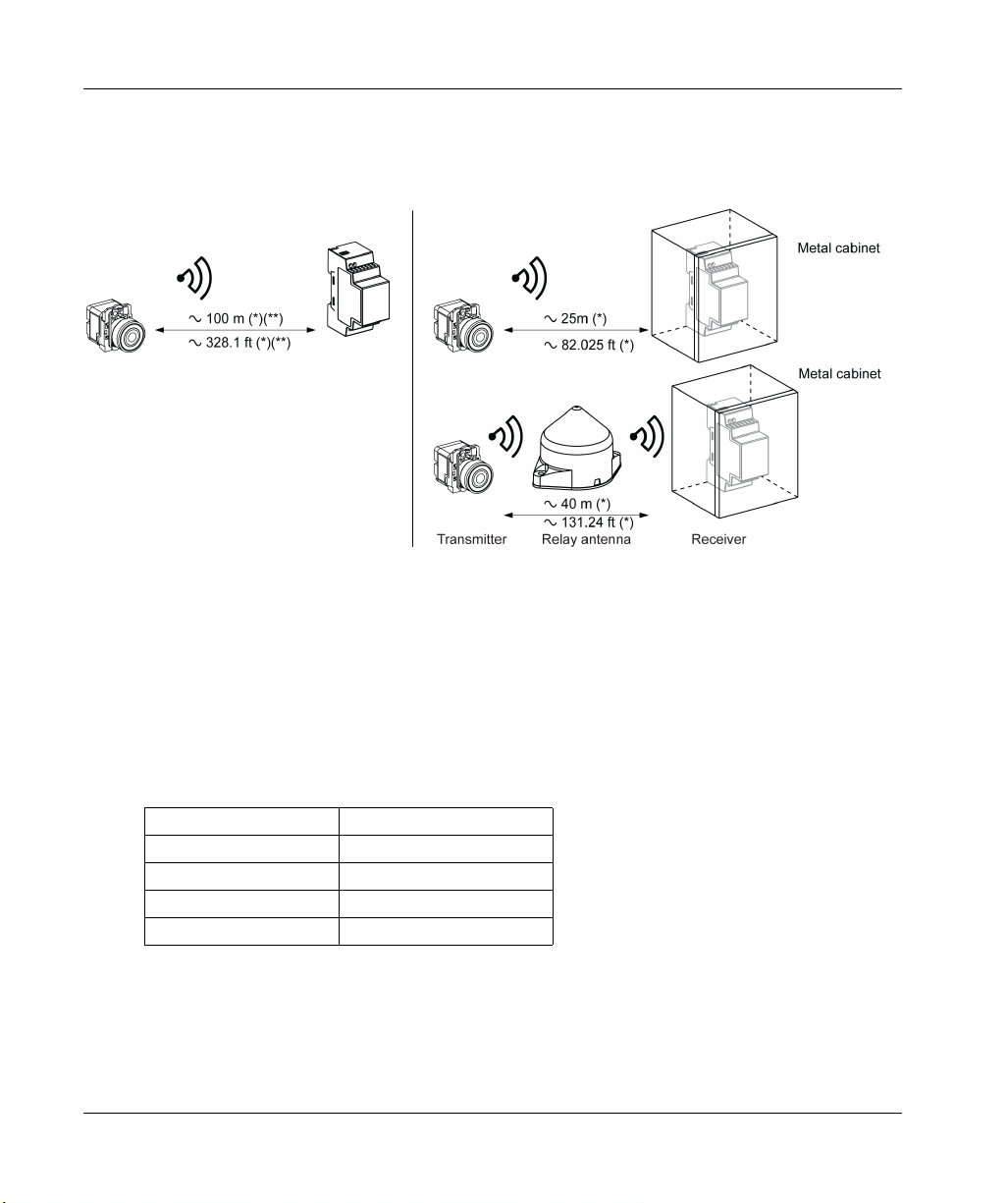
General Installation Instruction for Harmony XB5R
Maximum Distances
(*) Typical values that may be modified by the application environment.
(**) Free field (unobstructed).
NOTE:
The range may be increased by adding antenna ZBRA1.
The range is reduced if the transmitter is placed in a metal box (reduction factor: approx 10%).
Once wiring is complete, test the product in all possible active areas (while remaining within
range).
24
The level of signal attenuation depends on the materials through which the signal will pass:
Glass window 10...20 % (*)
Plaster wall 30...45 % (*)
Brick wall 60 % (*)
Concrete wall 70...80 % (*)
Metal structure 50...100 % (*)
(*) Values for indication purposes only. Actual values depend on the thickness and nature of the
material.
EIO0000000812 01/2014
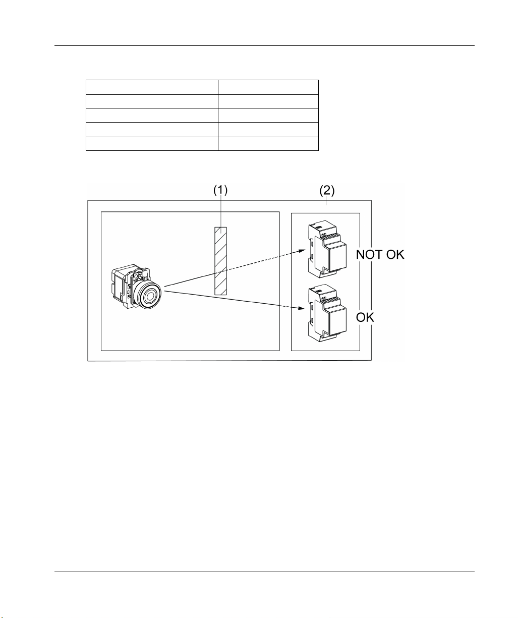
Installation Conditions
Transmitter operating temperature -25...+70° C (-13...+158° F)
Receiver operating temperature -25...+55° C (-13...+131° F)
Transmitter protection level IP65/NEMA3
Receiver protection level IP20
Transmitter shock resistance IK03
Mounting Tips
XB5R
1 Metal structure
2 Wall
NOTE: To ease the radio transmission, the best is to avoid obstacles. Find the best place to install
the transmitter and the receiver to have the minimum of obstacles.
EIO0000000812 01/2014 25

XB5R
Mounting Tips for Antenna
The antenna and the receiver are installed following their vertical axis.
26
The antenna is used to bypass the obstacle.
EIO0000000812 01/2014

XB5R
NOTE: The antenna should be placed before the obstacle. The signal will be amplified before the
obstacle to enable to go through it.
EIO0000000812 01/2014 27

XB5R
Transmitter and Pushbutton Assembly
Introduction
Follow these steps to install the transmitter and pushbutton.
Step 1: Mounting on a panel
This figure shows the diameter of the holes for ZB5R or ZB4R pushbuttons.
For all ZB5R••• heads except ZB5RZC2:
28
For ZB5RZC2 head:
EIO0000000812 01/2014
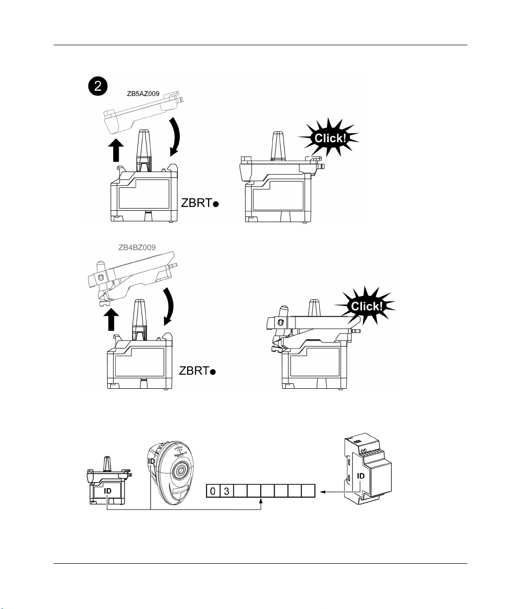
Step 2: Attach the mounting base to the transmitter
XB5R
Packages: ID Registration
NOTE: Please note and retain your transmitter ID. You will need it for an ID reset. The ID reset is
described in the Total Reset and ID Reset Procedure (see page 71).
EIO0000000812 01/2014 29

XB5R
Transmitter: ID Registration
Rope Pull Switch: ID Registration
30
EIO0000000812 01/2014

Steps 3, 4 and 5: Assembling Plastic Pushbuttons
Plastic pushbuttons are assembled as follows:
XB5R
Steps 3, 4 and 5: Assembling Metallic Pushbuttons
Metallic pushbuttons are assembled as follows:
EIO0000000812 01/2014 31

XB5R
Step 6: Pushbutton Cap Assembly
32
EIO0000000812 01/2014

Transmitter and Pushbutton Disassembly
Plastic Pushbutton Disassembling
Follow the four steps shown to disassemble the transmitter and the plastic pushbutton:
XB5R
Metallic Pushbutton Disassembling
Follow the three steps shown to disassemble the transmitter and the metallic pushbutton:
EIO0000000812 01/2014 33

XB5R
Models: ZBRT1, ZBRT2, ZBRTP enclosed in ZBRP1
FCC USA and I C Canada Compliance Statement
This device complies with part 15 of the FCC rules and Industry Canada licence-exempt RSS
standard(s). Operation is subject to the following two conditions:
1) This device may not cause harmful interference.
2) This device must accept any interference received, including interference that may cause
undesired operation of the device.
NOTE: Schneider Electric is not responsible for any radio or tv interference caused by
unauthorized modifications to this equipment. Changes or modifications not expressly approved
by Schneider Electric responsible for compliance could void the user’s authority to operate the
equipment.
Le présent appareil est conforme aux CNR d’Industrie Canada applicables aux appareils radio
exempts de licence. L’exploitation est autorisée aux deux conditions suivantes:
1) L’appareil ne doit pas produire de brouillage.
2) L’utilisateur de l’appareil doit accepter tout brouillage radioélectrique subi, même si le brouillage
est susceptible d’en compromettre le fonctionnement.
34
EIO0000000812 01/2014

Mounting Data for Rope Pull Switch
Rope Pull Switch Assembly
XB5R
EIO0000000812 01/2014 35

XB5R
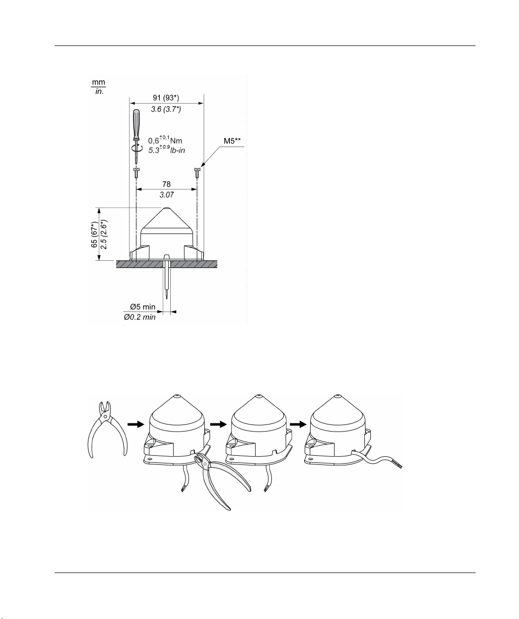
Mounting Instructions for ZBRM01 Handy Box
Assembly
36
(a) Except for ZB5RZC2.
(b) Before performing step 9, remove plastic protection from each side of the magnet.
EIO0000000812 01/2014

Disassembly
Location for Accessories
XB5R
EIO0000000812 01/2014 37

XB5R
Mounting Instructions for ZBRM21/ZBRM22 Mobile Boxes
Assembly
38
EIO0000000812 01/2014

Disassembly
Location for Accessories
XB5R
EIO0000000812 01/2014 39

XB5R
Mounting instructions For ZBRACS Support
Assembly
40
EIO0000000812 01/2014

Receiver Assembly and Disassembly
Instructions
Follow the steps in black for assembly.
Follow the steps in white for disassembly.
XB5R
Models: ZBRRA, ZBRRC, ZBRRD, and XB•RFB01
FCC USA and I C Canada Compliance Statement
This device complies with part 15 of the FCC rules and Industry Canada licence-exempt RSS
standard(s). Operation is subject to the following two conditions:
1) This device may not cause harmful interference.
2) This device must accept any interference received, including interference that may cause
undesired operation of the device.
NOTE: Schneider Electric is not responsible for any radio or tv interference caused by
unauthorized modifications to this equipment. Changes or modifications not expressly approved
by Schneider Electric responsible for compliance could void the user’s authority to operate the
equipment.
EIO0000000812 01/2014 41

XB5R
Le présent appareil est conforme aux CNR d’Industrie Canada applicables aux appareils radio
exempts de licence. L’exploitation est autorisée aux deux conditions suivantes:
1) L’appareil ne doit pas produire de brouillage.
2) L’utilisateur de l’appareil doit accepter tout brouillage radioélectrique subi, même si le brouillage
est susceptible d’en compromettre le fonctionnement.
In USA, our address and contact:
Schneider Electric
8001 Knightdale Blvd,
Knightdale, NC 27545
919-266-3671 (phone)
Receiver Dimensions
42
EIO0000000812 01/2014

Receiver Mounting Positions
(1): To enhance the signal reception, respect the above positioning.
(2): In a metal cabinet, the optimum place for the receiver is on the top and/or near the holes. This
position avoids obstacles and enhances reception.
NOTE: For XB•RFA02, XB5RMA04, ZBRRA, ZBRRC, ZBRRD: before disassembly for storage,
perform a total reset of the receiver memory. The total reset is described in the Total Reset and ID
Reset procedure (seepage71).
XB5R
EIO0000000812 01/2014 43

XB5R
Receiver Wiring Diagram
Wiring Diagram
The following figures show the wiring diagrams for the Harmony XB5R Receiver.
44
(1): 125 mA fast-blow fuse.
(2): 500 mA fuse from supplier Bussman® reference GMA-500 mA, 250 V 0.5 A fast-blow.
(3): Output contact ratings B300 Pilot Duty 3 A - 240 Vac Resistive.
(4): Output contact ratings B300 - R300 Pilot Duty 3 A - 240 Vac Resistive.
UL: Control of overvoltage to be provided after main service disconnect overcurrent device, with a
UL1449 TVSS device (Transient Voltage Surge Suppressor) tested as type 2 (6kV/3kA min), with
a MCOV (Maximum Continuous Operating Voltage) min rated to Phase to Phase voltage and a
VPR (Voltage Protection Rating) of 1.5 kV.
EIO0000000812 01/2014

XB5R
DANGER
HAZARD OF ELECTRIC SHOCK, EXPLOSION OR ARC FLASH
Disconnect all power before servicing equipment.
Use only the specified voltage when operating this equipment and any associated products.
Failure to follow these instructions will result in death or serious injury.
EIO0000000812 01/2014 45

XB5R
Relay Antenna Installation
Introduction
Observe the maximum distances between transmitter, antenna and receiver ( see page 24) and the
Mounting tips for antenna (seepage26).
Temporary Mounting
This temporary mounting is used to search the best place for the antenna in order to enhance the
radio signal.
46
NOTE: For temporary assembly the breakable part of the antenna must not be cut off.
EIO0000000812 01/2014
Axial Cable Route
XB5R
(*): Dimensions including gasket
(**): Screws not supplied
Radial Cable Route
EIO0000000812 01/2014 47

XB5R
Wiring Diagram
The following figure shows the relay antenna wiring diagram for Harmony XB5R.
(1): 500 mA from supplier Bussman® reference GMA-500mA, 250 V 0.5 A fast-blow.
UL: Control of Overvoltage to be provided after main service disconnect overcurrent device, with
a UL1449 TVSS device (Transient Voltage Surge Suppressor) Tested as type 2
(6 kV/3 kA min), with a MCOV (Maximum Continuous Operating Voltage) min. rated to Phase
to Phase voltage and a VPR (Voltage Protection Rating) of 1.5 kV.
UNINTENDED EQUIPMENT OPERATION
Do not use this equipment in safety critical machine functions.
Use appropriate safety interlocks where personnel and/or equipment hazards exist.
Install and operate this equipment in an enclosure appropriately rated for its intended
environment.
Failure to follow these instructions can result in death, serious injury, or equipment
damage.
WARNING
48
EIO0000000812 01/2014

Model: ZBRA1
FCC USA and I C Canada Compliance Statement
This device complies with part 15 of the FCC rules and Industry Canada licence-exempt RSS
standard(s). Operation is subject to the following two conditions:
1) This device may not cause harmful interference.
2) This device must accept any interference received, including interference that may cause
undesired operation of the device.
NOTE: Schneider Electric is not responsible for any radio or tv interference caused by
unauthorized modifications to this equipment. Changes or modifications not expressly approved
by Schneider Electric responsible for compliance could void the user’s authority to operate the
equipment.
Le présent appareil est conforme aux CNR d’Industrie Canada applicables aux appareils radio
exempts de licence. L’exploitation est autorisée aux deux conditions suivantes:
1) L’appareil ne doit pas produire de brouillage.
2) L’utilisateur de l’appareil doit accepter tout brouillage radioélectrique subi, même si le brouillage
est susceptible d’en compromettre le fonctionnement.
XB5R
EIO0000000812 01/2014 49

XB5R
50
EIO0000000812 01/2014

Harmony XB5R
Preparing For Use
EIO0000000812 01/2014
Preparing For Use
Chapter 3
Preparing For Use
Purpose
This chapter explains how to prepare the Harmony XB5R for use.
What Is in This Chapter?
This chapter contains the following topics:
Compatability Rules 52
Transmitter Types 53
LED Status 54
Output mode: Monostable - Bistable - Stop/Start - Set/Reset 56
Changing outputs from Monostable to Bistable for XB•RFA02, XB5RMA04, ZBRRA, and
ZBRRD
Changing Outputs From Monostable to Stop/Start for XB•RFA02, XB5RMA04, ZBRRA 61
How to Teach/Unteach Monostable, Bistable or Set/Reset Outputs for XB•RFA02, XB5RMA04,
ZBRRA, ZBRRC, and ZBRRD
How to Teach Stop/Start Outputs for XB•RFA02, XB5RMA04, ZBRRA 65
Lock/Unlock for XB•RFA02, XB5RMA04, ZBRRA, ZBRRC, and ZBRRD 68
Topic Page
59
63
EIO0000000812 01/2014 51

Preparing For Use
Compatability Rules
ZBRT2 transmitter is compatible with the following only:
ZBRR• receivers with firmware version 2.0 and higher
ZBRA1 relay antenna with firmware version 2.0 and higher
ZBRN• access points with firmware version higher than 1.2
52
EIO0000000812 01/2014

Transmitter Types
ZBRT1 and ZBRTP Transmitters
The radio message is sent when the button is pressed, signalled by a click. If the button is held
down, the message is not transmitted continuously. The message is not sent when the button is
released.
ZBRT2 Transmitter
Preparing For Use
The radio message is sent when the button is pressed, signaled by a click. If the button is held
down, the message is not transmitted continuously.
A second radio message is sent when the button is released. This message is not transmitted
continuously. It is transmitted once, at the release of the pushbutton.
This transmitter is used only for the set/reset output mode.
EIO0000000812 01/2014 53

Preparing For Use
LED Status
XB•RFA02 / XB5RMA04 and ZBRRA
ZBRRC
ZBRRD
54
NOTE: The signal strength LED indicates the value of the last signal received. The time out for the
LED is 1min 30s. This LED could also be switched off by pressing once the selection button of the
receiver.
EIO0000000812 01/2014

Synthesis
Preparing For Use
EIO0000000812 01/2014 55

Preparing For Use
Output mode: Monostable - Bistable - Stop/Start - Set/Reset
Monostable Output: Factory setting for packages and for ZBRRA, ZBRRC, and ZBRRD
Bistable Output: Only for XB•RFA02, XB5RMA04, ZBRRA and ZBRRD
56
EIO0000000812 01/2014

Stop/Start Output Standard Operation: Only for ZBRRA
Description for situations where Stop button does not have priority over Start button:
NOTE: This function requires two transmitters.
Set/Reset Output: Only for ZBRRA, ZBRRC, and ZBRRD
This output mode is active only when the ZBRT2 transmitter is used.
Preparing For Use
EIO0000000812 01/2014 57

Preparing For Use
NOTE:
1. Release and push again to resynchronise
2. Push and release again to resynchronise
Power outage and restore management
If the duration of a power outage is less than the power supply filtering time (approx. 7 ms), there
will be no impact on the receiver, which continues normal operation. Power outages longer than
the filtering time cause the product to restart when power is back. At restart the outputs will be in
their initial states with LEDs off.
58
EIO0000000812 01/2014

Preparing For Use
Changing outputs from Monostable to Bistable for XB•RFA02, XB5RMA04,
ZBRRA, and ZBRRD
Procedure
This procedure shows how to change Q1 and Q2 outputs from monostable to bistable.
The icons shown have the following meanings:
LEDs Meaning
On
Flashing
Monostable
Bistable
EIO0000000812 01/2014 59

Preparing For Use
60
EIO0000000812 01/2014

Preparing For Use
Changing Outputs From Monostable to Stop/Start for XB•RFA02, XB5RMA04,
ZBRRA
Procedure
This procedure shows how to change from monostable to Stop/Start for Q1 and Q2
The icons shown have the following meanings:
LEDs Meaning
On
Flashing
Monostable
Stop/Start
NOTE: When changing the output from Monostable to Stop/Start, all the registered ID for this
output will be automatically canceled from the receiver memory.
For information this also happens for the three following cases:
From bistable to Stop/Start.
From Stop/Start to monostable.
From Stop/Start to bistable.
When changing the output from Monostable to Bistable, or Bistable to Monostable, the registered
ID are not cancelled from the receiver memory.
EIO0000000812 01/2014 61

Preparing For Use
62
EIO0000000812 01/2014

Preparing For Use
How to Teach/Unteach Monostable, Bistable or Set/Reset Outputs for XB•RFA02,
XB5RMA04, ZBRRA, ZBRRC, and ZBRRD
Procedure
This procedure shows how to Teach/Unteach Q1 and Q2 outputs (ZBRRA) and Q1, Q2, Q3 and
Q4 outputs (ZBRRC) when using monostable or bistable outputs.
The icons shown have the following meanings:
LEDs Meaning
Green
Yellow
Flashing
Monostable
Bistable
Stop/Start
NOTE: It is possible to store a maximum of 32 ID. For example, 32 ID on Q1 output and 0 ID on
Q2 output, or 22 ID on Q1 output and 10 ID on Q2 output, can be stored on ZBRRA and ZBRRC.
When trying to teach a 33rd ID, all LEDs (except the power LED) flash quickly.
This 33rd ID is not taught.
EIO0000000812 01/2014 63

Preparing For Use
64
1) The Q1, Q2, Q3 or Q4 outputs will be active only 4 s after the teaching procedure.
2) The teaching procedure must be performed within 1 min 30 s.
3) The teach procedure on Q3 and Q4 outputs is the same. The Q3 or the Q4 output must be
selected and when the Q3 or Q4 LED is flashing at 2 Hz, the button can be taught.
EIO0000000812 01/2014

How to Teach Stop/Start Outputs for XB•RFA02, XB5RMA04, ZBRRA
Preliminary information
By default, the relay option is monostable. Before proceeding, change the relay option to
Stop/Start. Changing Outputs From Monostable to Stop/Start (see page 61) for more information.
Procedure
This procedure shows how to teach Q1 and Q2 outputs when using Stop/Start outputs.
The icons shown have the following meanings:
LEDs Meaning
Green
Yellow
Flashing
Monostable
Bistable
Stop/Start
Preparing For Use
NOTE: It is possible to store a maximum of 32 ID. For example, 32 ID on Q1 output and 0 ID on
Q2 output or 22 ID on Q1 output and 10 ID on Q2 output, can be stored on ZBRRA.
When trying to teach a 33rd, all LEDs (except the power LED) flash quickly.
This 33rd ID is not taught.
WARNING
UNINTENTED EQUIPMENT OPERATION
Do not leave the receiver without taught Stop button.
Failure to follow these instructions can result in death, serious injury, or equipment
damage.
NOTE: For the teach procedure the Stop buttons must be taught before the Start ones. If you start
by teaching a Start button (without any Stop button taught) all the LEDs flash. For the unteach
procedure all the Start buttons must be untaught before the Stop ones.
EIO0000000812 01/2014 65

Preparing For Use
How to Teach Q1 for Stop/Start
66
1) The Q1 output will be active only 4s after the teaching procedure.
2) The teaching procedure must be performed within 1min 30s.
EIO0000000812 01/2014

How to Teach Q2 for Stop/Start
Preparing For Use
1) The Q2 output will be active only 4s after the teaching procedure.
2) The teaching procedure must be performed within 1min 30s.
EIO0000000812 01/2014 67

Preparing For Use
Lock/Unlock for XB•RFA02, XB5RMA04, ZBRRA, ZBRRC, and ZBRRD
Introduction
Lock enables to block the menus access by non authorized persons. The functioning of the
receiver is not affected.
Mechanical Lock/Unlock
The following diagram shows how to perform buttons mechanical lock.
68
EIO0000000812 01/2014

Electronic Lock/Unlock
This procedure shows how to electronically lock/unlock the receiver.
Preparing For Use
EIO0000000812 01/2014 69

Preparing For Use
70
EIO0000000812 01/2014

Harmony XB5R
XB5R
EIO0000000812 01/2014
Other Functions for Harmony XB5R
Chapter 4
Other Functions for Harmony XB5R
Other Functions Description
Total Reset and ID Reset procedure for XB•RFA02, XB5RMA04, ZBRRA, ZBRRC, and ZBRRD
Total Reset: After a Total Reset the receiver is on factory setting. All outputs are set to monostable
function and all the registered ID are canceled.
ID Reset: This function enables to cancel an ID without having the push button (e.g: lost push
button). Only the transmitter ID is needed. The ID cancelation does not effect the output function.
NOTE: To reset an ID, the last 3 digits are needed. The first, second and third digits must be
entered as binary coded numbers in the receiver during the ID Reset procedure.
EIO0000000812 01/2014 71

XB5R
For ZBRRA and ZBRRD:
72
EIO0000000812 01/2014

For ZBRRC:
XB5R
EIO0000000812 01/2014 73

XB5R
74
EIO0000000812 01/2014

Harmony XB5R
XB5R
EIO0000000812 01/2014
Harmony XB5R ATEX Products
Chapter 5
Harmony XB5R ATEX Products
Purpose
This chapter provides an overview of the Harmony XB5R ATEX products.
What Is in This Chapter?
This chapter contains the following sections:
Section Topic Page
5.1 Transmission Products 76
5.2 Reception Products 84
5.3 Functions 91
EIO0000000812 01/2014 75

XB5R
Transmission Products
Section 5.1
Transmission Products
Overview
This section describes the ATEX transmitter products.
What Is in This Section?
This section contains the following topics:
Presentation of ATEX Transmission Components 77
ID Registration 79
Assembly, Disassembly, and Mounting Instructions 81
XAWGR•••EX Mounting Instructions 82
Topic Page
76
EIO0000000812 01/2014

Presentation of ATEX Transmission Components
ATEX Transmission Components
DANGER
HAZARD OF EXPLOSION
These devices must be installed, used, and maintained in accordance with:
Standard EN60079-14 (Explosive atmospheres), part 14 (Electrical installations design,
selection, and erection).
Standard EN60079-17 (Explosive atmospheres), part 17 (Electrical installations design,
selection, and erection).
Standard NF C15 100 (Low voltage electrical installations) - European equivalent: IEC 6034.
Regulations governing setup of the zone or zones for which the devices were designed.
Failure to follow these instructions will result in death or serious injury.
WARNING
UNINTENDED EQUIPMENT OPERATION
Do not use this equipment in safety critical machine functions.
Use appropriate safety interlocks where personnel and/or equipment hazards exist.
Do not disassemble, repair, or modify this equipment.
Install and operate this equipment in an appropriately rated enclosure for its intended
environment.
Install properly rated fuses.
Check that the control is inactive if the product falls during transit.
Failure to follow these instructions can result in death, serious injury, or equipment
damage.
XB5R
EIO0000000812 01/2014 77

XB5R
The following table describes the ATEX transmitter characteristics:
Designation Type Zone Cap Color Reference Mass
Plastic handy box – Mining
Ex ib Ι Mb
Gas
Ex ib ΙΙB T6 Gb
Dust
Ex ib ΙΙΙC T85ºC Db IP65
Transmitter Metallic pushbutton Mining
Plastic pushbutton Without cap ZB5RTA0EX 0.043 kg
Plastic handy box – – ZBRM01EX 0.150 kg
Rope pull switch – – ZBRP1EX 0.140 kg
Button box XAW G 1-button box – XAWGR100EX 0.500 kg
XAW G 2-button box – XAWGR200EX 0.550 kg
XAW G 3-button box – XAWGR300EX 0.700 kg
Ex ib Ι Mb
Gas
Ex ib ΙΙC T6 Gb
Dust
Ex ib ΙΙΙC T85ºC Db IP65
– ZBRM01BEX 0.100 kg
(0.220 lb)
Without cap ZB4RTA0EX 0.083 kg
(0.183 lb)
(0.095 lb)
(0.331 lb)
(0.309 lb)
(1.102 lb)
(1.213 lb)
(1.543 lb)
78
NOTE: The operating characteristics are same as non-ATEX products.
EIO0000000812 01/2014

ID Registration
Transmitter: ID Registration
Transmitter: Handybox ID Registration
XB5R
Transmitter: Pushbutton ID Registration
EIO0000000812 01/2014 79

XB5R
Transmitter: Handybox ID Registration
Rope Pull Switch: ID Registration
80
EIO0000000812 01/2014

Assembly, Disassembly, and Mounting Instructions
ZB•RTA0EX and ZBRM01•EX Assembly
To install transmitter and pushbutton, refer to Transmitter and Pushbutton Assembly
(seepage28).
ZB•RTA0EX and ZBRM01•EX Disassembly
To disassemble, refer to Transmitter and Pushbutton Disassembly (seepage33).
ZBRP1EX Mounting Instructions
To mount a rope pull switch, refer to Mounting Data for Rope Pull Switch (seepage35).
XB5R
EIO0000000812 01/2014 81

XB5R
XAWGR•••EX Mounting Instructions
Button Box Assembly
Models: ZBRT1, ZBRTP enclosed in ZBRP1
FCC USA and I C Canada Compliance Statement
This device complies with part 15 of the FCC rules and Industry Canada licence-exempt RSS
standard(s). Operation is subject to the following two conditions:
1) This device may not cause harmful interference.
2) This device must accept any interference received, including interference that may cause
undesired operation of the device.
NOTE: Schneider Electric is not responsible for any radio or tv interference caused by
unauthorized modifications to this equipment. Changes or modifications not expressly approved
by Schneider Electric responsible for compliance could void the user’s authority to operate the
equipment.
82
EIO0000000812 01/2014

XB5R
Le présent appareil est conforme aux CNR d’Industrie Canada applicables aux appareils radio
exempts de licence. L’exploitation est autorisée aux deux conditions suivantes:
1) L’appareil ne doit pas produire de brouillage.
2) L’utilisateur de l’appareil doit accepter tout brouillage radioélectrique subi, même si le brouillage
est susceptible d’en compromettre le fonctionnement.
EIO0000000812 01/2014 83

XB5R
Reception Products
Section 5.2
Reception Products
Overview
This section describes the ATEX reception products.
What Is in This Section?
This section contains the following topics:
Presentation of ATEX Reception Components 85
ZBRA1DEX Mounting and Wiring Instructions 87
ZBRA1EX Mounting and Wiring Instructions 89
Topic Page
84
EIO0000000812 01/2014

Presentation of ATEX Reception Components
ATEX Reception Components
DANGER
HAZARD OF EXPLOSION
These devices must be installed, used, and maintained in accordance with:
Standard EN60079-14 (Explosive atmospheres), part 14 (Electrical installations design,
selection, and erection).
Standard EN60079-17 (Explosive atmospheres), part 17 (Electrical installations design,
selection, and erection).
Standard EN60079-31 (Explosive atmospheres), part 31 (Equipment dust ignition protection
by enclosure ‘t’).
Standard NF C15 100 (Low voltage electrical installations) - European equivalent: IEC 60364.
Regulations governing setup of the zone or zones for which the devices were designed.
Failure to follow these instructions will result in death or serious injury.
WARNING
UNINTENDED EQUIPMENT OPERATION
Do not use this equipment in safety critical machine functions.
Use appropriate safety interlocks where personnel and/or equipment hazards exist.
Install and operate this equipment in an approprately rated enclosure for its intended
environment.
Failure to follow these instructions can result in death, serious injury, or equipment
damage.
XB5R
EIO0000000812 01/2014 85

XB5R
The following table describes the ATEX receiver component characteristics:
Designation Zone Reference Mass
Relay antenna in plastic
protection
Relay antenna in glass
protection
Dust
Ex tb ΙΙΙC T85º C Db
IP65
Gas
Ex d ΙΙC T6 Gb
Dust
Ex tb ΙΙΙC T85º C Db
IP65
ZBRA1DEX 1.000 kg (2.205 lb)
ZBRA1EX 3.100 kg (6.834 lb)
86
NOTE: The operating characteristics are same as non-ATEX products.
EIO0000000812 01/2014

ZBRA1DEX Mounting and Wiring Instructions
Mounting and Wiring Instructions
XB5R
NOTE: The cable gland must be tightened (Step 2 and 3).
EIO0000000812 01/2014 87

XB5R
NOTE: Schneider Electric recommends to use adapters instead of the cable gland to change the
shape of conduit entries if needed.
(1): 500 mA fuse from supplier Bussman® reference GMA-500 mA, 250 V 0.5 A fast-blow.
NOTE: The fuse must be installed outside the ATEX area or protected by Ex protection mode.
88
EIO0000000812 01/2014

ZBRA1EX Mounting and Wiring Instructions
Mounting and Wiring Instructions
XB5R
NOTE: The cable gland must be tightened (Step 2 and 3).
NOTE: Schneider Electric recommends to use sealing fittings (with resin component) instead of
the cable gland to restrict the passage of gases, vapors, or flames from one portion of the electrical
installation to another at atmospheric pressure and normal ambient temperatures.
EIO0000000812 01/2014 89

XB5R
NOTE: Schneider Electric recommends to use adapters instead of the cable gland to change the
shape of conduit entries if needed.
(1): 500 mA fuse from supplier Bussman® reference GMA-500 mA, 250 V 0.5 A fast-blow.
NOTE: The fuse must be installed outside the ATEX area or protected by Ex protection mode.
Models: ZBRT1, ZBRTP enclosed in ZBRP1
FCC USA and I C Canada Compliance Statement
This device complies with part 15 of the FCC rules and Industry Canada licence-exempt RSS
standard(s). Operation is subject to the following two conditions:
1) This device may not cause harmful interference.
2) This device must accept any interference received, including interference that may cause
undesired operation of the device.
NOTE: Schneider Electric is not responsible for any radio or tv interference caused by
unauthorized modifications to this equipment. Changes or modifications not expressly approved
by Schneider Electric responsible for compliance could void the user’s authority to operate the
equipment.
Le présent appareil est conforme aux CNR d’Industrie Canada applicables aux appareils radio
exempts de licence. L’exploitation est autorisée aux deux conditions suivantes:
1) L’appareil ne doit pas produire de brouillage.
2) L’utilisateur de l’appareil doit accepter tout brouillage radioélectrique subi, même si le brouillage
est susceptible d’en compromettre le fonctionnement.
90
EIO0000000812 01/2014

Functions
Section 5.3
Functions
Functions of ATEX Components
List of Components
The following table shows the ATEX components and the functionally equivalent non-ATEX
components.
ATEX Reference Non-ATEX Components
ZB5RTA0EX ZBRT1
ZB4RTA0EX ZBRT1
XB5R
XAWGR100EX ZBRT1
EIO0000000812 01/2014 91

XB5R
ATEX Reference Non-ATEX Components
XAWGR200EX ZBRT1
XAWGR300EX ZBRT1
92
ZBRA1EX ZBRA1
EIO0000000812 01/2014

ATEX Reference Non-ATEX Components
ZBRA1DEX ZBRA1
ZBRM01EX ZBRT1
ZBRM01BEX ZBRT1
XB5R
EIO0000000812 01/2014 93

XB5R
ATEX Reference Non-ATEX Components
ZBRP1EX ZBRT1
94
EIO0000000812 01/2014
 Loading...