

Page 1
The information provided in this documentation contains general descriptions and/or technical characteristics of the performance of the products contained herein.
This documentation is not intended as a substitute for and is not to be used for determining suitability or reliability of these products for specific user applications.
It is the duty of any such user or integrator to perform the appropriate and complete risk analysis, evaluation and testing of the products with respect to the relevant specific application or use thereof.
Neither Schneider Electric Industries SAS nor any of its affiliates or subsidiaries shall be responsible or liable for misuse of the information contained herein.
Product data sheet
Characteristics
RSB2A080BDS
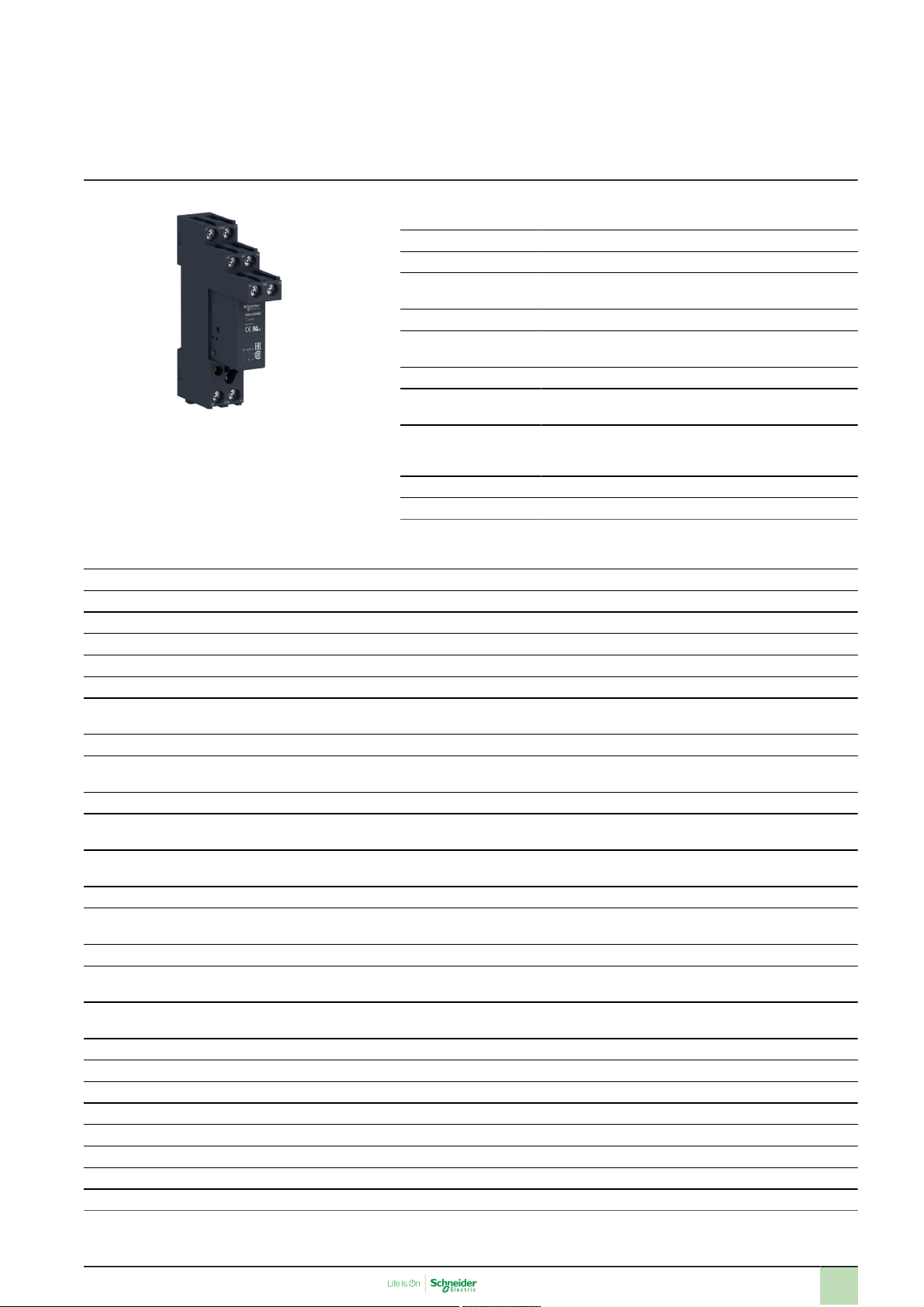
Harmony, Interface plug-in relay with socket, 8
A, 2 CO, 24 V DC
Main
Range of product Harmony Electromechanical Relays
Series name Interface relay
Product or component
type
Device short name RSB
Contacts type and
composition
Contact operation Standard
[Uc] control circuit
voltage
[Ithe] conventional
enclosed thermal
current
Status LED Without
Control type Without push-button
Plug-in relay
2 C/O
24 V DC
8A at -40…40°C
Complementary
Shape of pin Flat
Average coil resistance 1440Ohm network: DC at 20 °C +/- 10 %
[Ue] rated operational voltage 19.2...26.4 V DC
[Ui] rated insulation voltage 400V conforming to EN/IEC 60947
[Uimp] rated impulse withstand voltage 3.6kV conforming to IEC 61000-4-5
Contacts material Silver alloy (Ag/Ni)
[Ie] rated operational current 4A (AC-1/DC-1) NC conforming to IEC
Minimum switching current 5mA
Maximum switching voltage 300V DC
Minimum switching voltage 5V
Maximum switching capacity 2000 VA AC
Resistive rated load 8A at 250 V AC
Minimum switching capacity 300 mW at 5mA
Operating rate <= 600 cycles/hour under load
Mechanical durability 30000000cycles
Electrical durability 100000Cycles, 8A at 250 V, AC-1 NO
Operating time 4 ms between coil de-energisation and making of the Off-delay contact
Marking CE
Average coil consumption 0.45W DC
Drop-out voltage threshold >= 0.1 Uc DC
Safety reliability data B10d = 100000
Protection category RT I
Operating position Any position
Sale per indivisible quantity 10
Device presentation Complete product
8A (AC-1/DC-1) NO conforming to IEC
400V AC
224 W DC
8A at 28 V DC
<= 72000 cycles/hour no-load
100000cycles, 4A at 250 V, AC-1 NC
9 ms between coil energisation and making of the On-delay contact
Oct 4, 2022
1
Page 2
Environment
Dielectric strength 1000V AC between contacts
Standards EN/IEC 61810-1
Product certifications GOST
Ambient air temperature for storage -40…85°C
Vibration resistance +/- 1 mm (f= 10…55Hz) conforming to EN/IEC 60068-2-6
IP degree of protection IP40 conforming to EN/IEC 60529
Shock resistance 10 gn (duration = 11ms) for not operating conforming to EN/IEC 60068-2-27
Ambient air temperature for operation -40…70°C (AC)
2500V AC between poles
5000V AC between coil and contact
UL 508
CSA C22.2 No 14
UL
CSA
5 gn (duration = 11ms) for in operation conforming to EN/IEC 60068-2-27
-40…85°C (DC)
Offer Sustainability
EU RoHS Directive
Toxic heavy metal free Yes
Mercury free Yes
RoHS exemption information
China RoHS Regulation
Environmental Disclosure
WEEE The product must be disposed on European Union markets following specific
Pro-active compliance (Product out of EU RoHS legal scope) EU RoHS
Declaration
Yes
China RoHS Declaration
Product Environmental Profile
waste collection and never end up in rubbish bins
2
Page 3

Product data sheet
Dimensions Drawings
Dimensions
Relay Complete with Socket
RSB2A080BDS
(1) Relays
(2) Socket
3
Page 4
Product data sheet
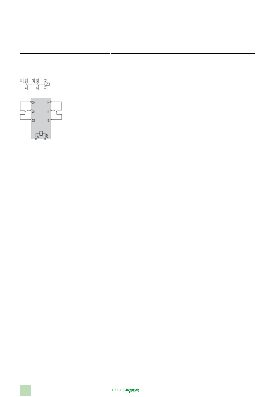
Connections and Schema
Wiring Diagram
NOTE: For DC input, A1 have to be +, otherwise it would short circuit from protection module
RSB2A080BDS
4
Page 5
Product data sheet
RSB2A080BDS
Performance Curves
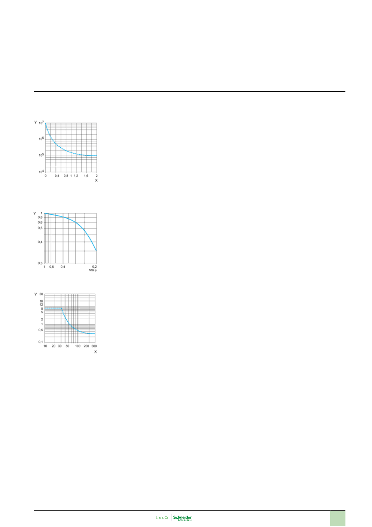
Electrical Durability of Contacts
Durability (inductive load) = durability (resistive load) x reduction coefficient.
Resistive AC load
X Switching capacity (kVA)
Y Durability (Number of operating cycles)
Reduction coefficient for inductive AC load (depending on power factor cos ϕ)
Y Reduction coefficient (A)
Maximum switching capacity on resistive DC load
X Voltage DC
Y Current DC
Note : These are typical curves, actual durability depends on load, environment, duty cycle, etc.
5
 Loading...