

Page 1
2354235 11/2008
Altivar 61/71
Profibus DP
User manual
11/2009
1755873
www.schneider-electric.com
Page 2

Page 3

Contents
While every precaution has been taken in the preparation of this document,
Schneider Electric SA assumes no liability for any omissions or errors i t may contain,
nor for any damages resulting from the application or use of the information herein.
The products and options descr ibed in th is document may be changed or modifi ed at
any time, either from a technical point of view or in the way they are operated.
Their description can in no way be considered contractual.
Before you begin_____________________________________________________________________________________________ 4
Documentation structure_______________________________________________________________________________________ 5
Introduction_________________________________________________________________________________________________ 6
Presentation _____________________________________________________________________________________________ 6
Notation ________________________________________________________________________________________________ 6
Hardware setup _____________________________________________________________________________________________ 7
Receipt _________________________________________________________________________________________________ 7
Installing the card in the drive________________________________________________________________________________ 7
Connection to the bus______________________________________________________________________________________ 8
Recommendations ________________________________________________________________________________________ 9
Configuration ______________________________________________________________________________________________ 10
Configuring the switches___________________________________________________________________________________ 10
Control-signal configuration ________________________________________________________________________________ 12
Configuring PZDs (communication scanner) ___________________________________________________________________ 15
Configuring communication fault management _________________________________________________________________ 16
Configuring monitored parameters___________________________________________________________________________ 17
Diagnostics________________________________________________________________________________________________ 18
Controlling the address and speed of the bus __________________________________________________________________ 18
LEDs__________________________________________________________________________________________________ 18
Control-signal diagnostics__________________________________________________________________________________ 19
Communication faults_____________________________________________________________________________________ 22
Card fault ______________________________________________________________________________________________ 22
Software setup _____________________________________________________________________________________________ 23
Profibus DP protocol______________________________________________________________________________________ 23
Output PZDs____________________________________________________________________________________________ 24
Input PZDs _____________________________________________________________________________________________ 25
PKW aperiodic service ____________________________________________________________________________________ 26
Software setup using PL7_____________________________________________________________________________________ 28
1755873 11/2009 3
Page 4

Before you begin
Read and understand these instructions before performing any procedure with thi s drive.
DANGER
HAZARDOUS VOLTAGE
• Read and understand this manual before installing or operating the drive. Installation, adjustment, repair, and
maintenance must be performed by qualified personnel.
• The user is responsible for compliance with all international and national electrical standards in force concerning
protective grounding of all equipment.
• Many parts in this variable speed drive, including printed wiring boards, operate at line voltage. DO NOT TOUCH.
Use only electrically insulated tools.
• DO NOT touch unshielded components or terminal strip screw connections with voltage present.
• DO NOT short across terminals PA and PC or across the DC bus capacitors.
• Install and close all covers before applying power or starting and stopping the drive.
• Before servicing the variable speed drive:
- Disconnect all power
- Place a "DO NOT TURN ON" label on the variable speed drive disconnect
- Lock the disconnect in the open position
• Disconnect all power including external control power that may be present before servicing the drive. WAIT 15
MINUTES for the DC bus capacitors to discharge. Then follow the DC bus voltage measurement procedure given
in the Installation Manual to verify that the DC voltage is less than 45 Vdc. The drive LEDs are not accurate indicators
of the absence of DC bus voltage.
Electric shock will result in death or serious injury
CAUTION
DAMAGED EQUIPMENT
Do not operate or install any drive that appears damaged.
Failure to follow this instruction can result in equipment damage.
4 1755873 11/2009
Page 5

Documentation structure
Installation manual
This manual describes:
• How to assemble the drive
• How to connect the drive
Programming manual
This manual describes:
• The functions
• The parameters
• How to use the drive display terminal (integrated display terminal and graphic display terminal)
Communication parameters manual
This manual describes:
• The drive parameters with specific information (addresses, formats, etc.) for use via a bus or communication network
• The operating modes specific to communication (status chart)
• The interaction between communication and local control
Modbus, CANopen, Ethernet, Profibus, INTERBUS, Uni-Telway, FIPIO, Modbus Plus, DeviceNet ...
manuals
These manuals describe:
• Connection to the bus or network
• Configuration of the communication-specific parameters via the integrated display terminal or the graphic display terminal
• Diagnostics
• Software setup
• The communication services specific to the protocol
ATV58-58F/ATV71 compatibility manual
This manual describes the differences between the Altivar 71 and the Altivar 58/58F.
It explains how to replace an Altivar 58 or 58F, including how to replace drives communicating on a bus or network.
1755873 11/2009 5
Page 6

Introduction
Presentation
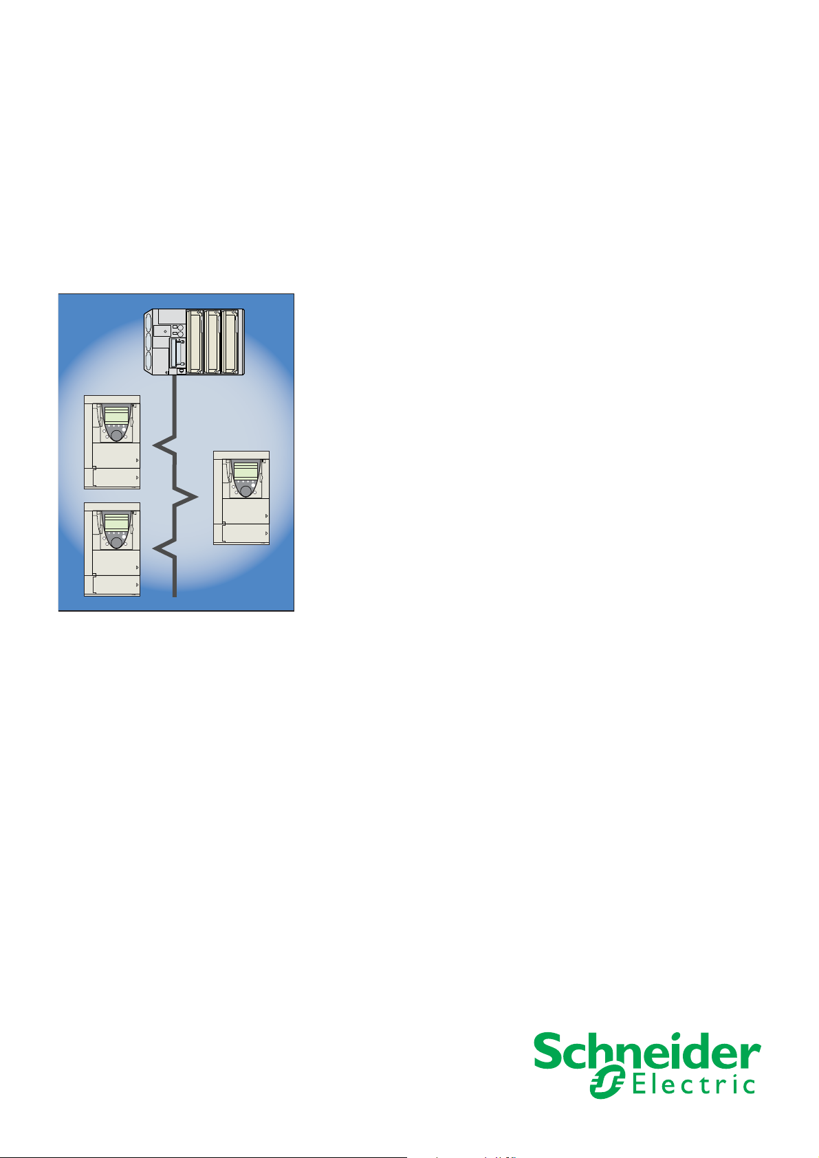
The Profibus DP communication card (catalog number VW3 A3 307) is used to connect an Altivar 61 / 71 drive to a Profibus DP bus.
Data is exchanged in order to make use of all the Altivar 61 / 71 functions:
• Configuring functions
• Uploading adjustment parameters
• Control-signaling
• Monitoring
• Diagnostics
The card has a 9-pin female SUB-D connector for connection to the Profibus DP bus.
The connector and cable for connection to the Profibus DP bus must be ordered separately.
Notation
Drive terminal displays
The graphic display terminal menus are shown in square brackets.
Example:
The integrated 7-segment display terminal menus are shown in round brackets.
Example: (COM-).
[1.9 COMMUNICATION].
Parameter names are displayed on the graphic display terminal in square brackets.
Example:
Parameter codes are displayed on the integrated 7-segment display terminal in round brackets.
Example: (LFF).
[Fallback speed]
Formats
In this manual, hexadecimal values are written as follows: 16#.
6 1755873 11/2009
Page 7
Hardware setup
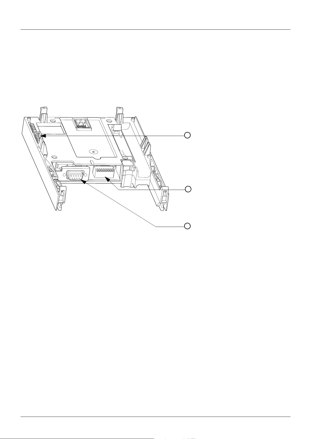
LEDs1
2
Addressing switches, also used to adjust
the drive process data exchange mode
3 9-pin female SUB-D connector
Receipt
• Check that the card catalog number marked on the label is the same as that on the delivery note corresponding to the purchase order.
• Remove the option card from its packaging and check that it has not been damaged in transit.
Presentation
Installing the card in the drive
See the Installation Manual.
1755873 11/2009 7
Page 8
Hardware setup
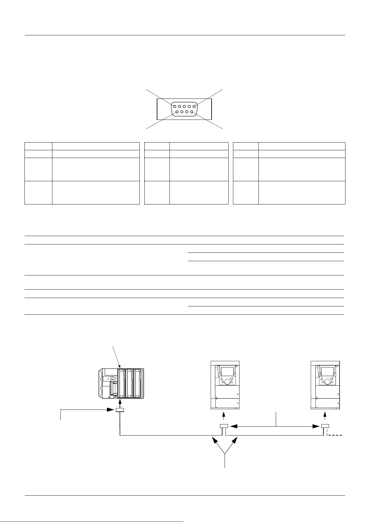
Pin 5
Pin 1
Pin 6Pin 9
9-pin female SUB-D
Profibus DP communication module: TSX-PBY100
TSX PREMIUM PLC
Altivar 61 / 71 Altivar 61 / 71
Connector with line
terminator
490 NAD 911 03
Profibus DP connection cable
TSX PBS CA
p00
(100 or 400 m)
Intermediate
connectors
490 NAD 911 04
Connection to the bus
Connector pinout
The transmission interface conforms to the RS 485 standard and is electrically isolated from the drive.
Pin Signal Pin Signal Pin Signal
1 Not connected 4 Not connected 7 Not connected
2 Not connected 5 DGND (Ground) 8 RxD/TxD-P
(Reception/Transmission +)
3 RxD/TxD-N
(Reception/Transmission -)
6 VP (5 volts) 9 Not connected
Connection accessories
Profibus DP bus connection elements
Description Used Catalog number
Connectors With line terminator 490 NAD 911 03
Intermediate connection 490 NAD 911 04
Intermediate connection and
connector port
Profibus DP bus connection cables
Description Length Catalog number
Profibus DP connection cables 100 m TSX PBS CA 100
400 m TSX PBS CA 400
Example of connection:
490 NAD 911 05
8 1755873 11/2009
Page 9

Hardware setup
Recommendations
• The user can select the data rate from a range of 9.6 kbps to 12 Mbps. Thi s select ion, made when s tarting up t he network, applies to all
the bus subscribers.
• The maximum segment length is in inverse proportion to the data rate.
Data rate (kbps) 9.6 19.2 93.75 187.5 500 1500 3000 6000 12000
Distance/segment (m) 1200 1200 1200 1000 400 200 100 100 100
Repeaters can be used to cover greater distances.
• The bus ends with a line terminator at each end of the segment.
• Do not connect more than 32 stations per segment without a repeater, or more than 127 with a repeater.
• Keep the bus away from the power cables (clearance of at least 30 cm).
• If it is necessary for power cables to cross each other, be sure they cross at right angles.
1755873 11/2009 9
Page 10

Configuration
Configuring the switches
Note:
A new configuration of the switches (address and mode) will only be appli ed after the next power on of the drive.
Selecting the operating mode
The switch furthest to the left is used to determine the type of cyclic exchanges performed by the drive:
• Switch 0 (OFF): Altivar 61 / 71 mode
• Switch 1 (ON): Altivar 58 compatibility mode
This manual only describes Altivar 61 / 71 mode. To find out about Altiva r 58 compat ib il ity mode , ref er to the ATV58 -5 8F/ATV7 1 migration
manual.
10 1755873 11/2009
Page 11

Configuration
Coding the drive address
An Altivar 61 / 71 is identified on the bus by its address, coded between 0 and 126.
The address corresponds to the binary number given by position 0 (up/OFF) or 1 (down/ON) of the 7 switches on the right of the card.
The least significant bits are on the right.
The table below indicates the positions of the switches for all configurable addresses:
Addr. Switches Addr. Switches Addr. Switches Addr. Switches
0 0000 0000 032 0010 0000 064 0100 0000 096 0110 0000
1 0000 0001 033 0010 0001 065 0100 0001 097 0110 0001
002 0000 0010 034 0010 0010 066 0100 0010 098 0110 0010
003 0000 0011 035 0010 0011 067 0100 0011 099 0110 0011
004 0000 0100 036 0010 0100 068 0100 0100 100 0110 0100
005 0000 0101 037 0010 0101 069 0100 0101 101 0110 0101
006 0000 0110 038 0010 0110 070 0100 0110 102 0110 0110
007 0000 0111 039 0010 0111 071 0100 0111 103 0110 0111
008 0000 1000 040 0010 1000 072 0100 1000 104 0110 1000
009 0000 1001 041 0010 1001 073 0100 1001 105 0110 1001
010 0000 1010 042 0010 1010 074 0100 1010 106 0110 1010
011 0000 1011 043 0010 1011 075 0100 1011 107 0110 1011
012 0000 1100 044 0010 1100 076 0100 1100 108 0110 1100
013 0000 1101 045 0010 1101 077 0100 1101 109 0110 1101
014 0000 1110 046 0010 1110 078 0100 1110 110 0110 1110
015 0000 1111 047 0010 1111 079 0100 1111 111 0110 1111
016 0001 0000 048 0011 0000 080 0101 0000 112 0111 0000
017 0001 0001 049 0011 0001 081 0101 0001 113 0111 0001
018 0001 0010 050 0011 0010 082 0101 0010 114 0111 0010
019 0001 0011 051 0011 0011 083 0101 0011 115 0111 0011
020 0001 0100 052 0011 0100 084 0101 0100 116 0111 0100
021 0001 0101 053 0011 0101 085 0101 0101 117 0111 0101
022 0001 0110 054 0011 0110 086 0101 0110 118 0111 0110
023 0001 0111 055 0011 0111 087 0101 0111 119 0111 0111
024 0001 1000 056 0011 1000 088 0101 1000 120 0111 1000
025 0001 1001 057 0011 1001 089 0101 1001 121 0111 1001
026 0001 1010 058 0011 1010 090 0101 1010 122 0111 1010
027 0001 1011 059 0011 1011 091 0101 1011 123 0111 1011
028 0001 1100 060 0011 1100 092 0101 1100 124 0111 1100
029 0001 1101 061 0011 1101 093 0101 1101 125 0111 1101
030 0001 1110 062 0011 1110 094 0101 1110
031 0001 1111 063 0011 1111 095 0101 1111
126 0111 1110
0111 1111
• Addresses 0 and 1 are usually reserved for the Profibus DP masters and must not be used to configure the Profibus DP address on an
Altivar 61 / 71.
• It is not advised to use address 126, which is incompatible with SSA service (Set Slave Address) and with some network configuration
softwares (Sycon, ...).
Examples:
Address 23
Address 89
The address can be checked via the display terminal (see Diagnostics section).
1755873 11/2009 11
Page 12

Configuration
Control-signal configuration
There are a number of possible configurations. For more information, refer to the programmi ng and communication parameters manuals.
The configurations below are just some of the possibilities available.
Control via Profibus DP in I/O profile
The command and the target come from Profibus DP.
Control is in I/O profile.
Configure the following parameters:
Parameter Value Comment
Profile I/O profile The run command is simply obtained by bit 0 of the command word.
Target 1 configuration Network card The target comes from Profibus DP.
Command 1 configuration Network card The command comes from Profibus DP.
Configuration via the graphic display terminal or the integrated display terminal:
Menu Parameter Value
[1.6 - COMMAND] (CtL-) [Profile] (CHCF) [I/O profile] (IO)
[Ref. 1 chan] (Fr1) [Com. opt card] (nEt)
[Cmd channel 1] (Cd1) [Com. opt card] (nEt)
Control via Profibus DP or via the terminals in I/O profile
The command and the target both come from Profibus DP or the terminal s. Input LI5 at the terminal s is used to switch between Pr ofibus DP
and the terminals.
Control is in I/O profile.
Configure the following parameters:
Parameter Value Comment
Profile I/O profile The run command is simply obtained by bit 0 of the command word.
Target 1 configuration Network card Target 1 comes from Profibus DP.
Target 1B configuration Analog input 1 on the terminals Target 1B comes from input AI1 on the terminals.
Target switching Input LI5 Input LI5 switches the target (1
Command 1 configuration Network card Command 1 comes from Profibus DP.
Command 2 configuration Terminals Command 2 comes from th e terminals.
Command switching Input LI5 Input LI5 switches the command.
Target 1B is connected to the functions (summing, PID, etc.) that remain active, even after switching.
Configuration via the graphic display terminal or the integrated display terminal:
Menu Parameter Value
↔ 1B).
[1.6 - COMMAND] (CtL-) [Profile] (CHCF) [I/O profile] (IO)
[Ref. 1 chan] (Fr1) [Com. card] (nEt)
[Cmd channel 1] (Cd1) [Com. card] (nEt)
[Cmd channel 2] (Cd2) [Terminals] (tEr)
[Cmd switching] (CCS) [LI5] (LI5)
[1.7 APPLICATION FUNCT.] (FUn-)
[REFERENCE SWITCH.]
[Ref. 1B chan]
[Ref 1B switching] (rCb) [LI5] (LI5)
(Fr1b) [AI1 ref.] (AI1)
12 1755873 11/2009
Page 13

Configuration
Control via Profibus DP in Drivecom profile
The command and the target come from Profibus DP.
Control is in Drivecom profile.
Configure the following parameters:
Parameter Value Comment
Profile Combined Drivecom profile The run commands are in Drivecom profile, the command and the target come
Target 1 configuration Network card The command comes from Profibus DP.
Configuration via the graphic display terminal or the integrated display terminal:
Menu Parameter Value
[1.6 - COMMAND] (CtL-) [Profile] (CH CF) [Combined] (SIM) (factory setting)
[Ref. 1 chan] (Fr1) [Com. card] (nEt)
Control via Profibus DP or the terminals in Drivecom profile
The command and the target both come from Profibus DP or the terminals. Input LI5 at the terminals is used to switch between
Profibus DP and the terminals.
Control is in Drivecom profile.
from the same channel.
Configure the following parameters:
Parameter Value Comment
Profile Combined Drivecom profile The run commands are in Drivecom profile, the command and t he target
Target 1 configuration Network card Target 1 comes from Profibus DP.
Target 2 configuration Analog input 1 on the terminals Target 2 comes from input AI1 on the terminals.
Target switching Input LI5 Input LI5 switches the target (1
Configuration via the graphic display terminal or the integrated display terminal:
Menu Parameter Value
come from the same channel.
↔ 2) and the command.
[1.6 - COMMAND] (CtL-) [Profile] (CHCF) [Combined] (SIM)
[Ref. 1 chan] (Fr1) [Com. card] (nEt)
[Ref. 2 chan] (Fr2) [AI1 ref.] (AI1)
[Ref 2 switching] (rFC) [LI5] (LI5)
1755873 11/2009 13
Page 14

Configuration
Control in Drivecom profile via Profibus DP and target switching at the terminals
The command comes from Profibus DP.
The target comes either from Profibus DP or from the termi nals. Input LI5 at the termina ls is used to switc h the target between Profibus DP
and the terminals.
Control is in Drivecom profile.
Configure the following parameters:
Parameter Value Comment
Profile Separate Drivecom profile The run commands are in Drivecom profile, the command and the target
Target 1 configuration Network card Target 1 comes from Profibus DP.
Target 1B configuration Analog input 1 on the terminals Target 1B comes from input AI1 on the terminals.
Target switching Input LI5 Input LI5 switches the target (1
Command 1 configuration Network card Command 1 comes from Profi bus DP.
Command switching Channel 1 Channel 1 is the command channel.
Target 1B is connected to the functions (summing, PID, etc.) that remain active, even after switching.
Configuration via the graphic display terminal or the integrated display terminal:
Menu Parameter Value
[1.6 - COMMAND] (CtL-) [Profile] (CHCF) [Separate] (SEP)
[1.7 APPLICATION FUNCT.] (FUn-)
[REFERENCE SWITCH.]
can come from different channels.
↔ 1B).
[Ref. 1 chan] (Fr1) [Com. card] (nEt)
[Cmd channel 1] (Cd1) [Com. card] (nEt)
[Cmd switching] (CCS) [ch1 active] (Cd1)
[Ref. 1B chan]
(Fr1b) [AI1 ref.] (AI1)
[Ref 1B switching] (rCb) [LI5] (LI5)
14 1755873 11/2009
Page 15

Configuration
Configuring PZDs (communication scanner)
PZDs are configured by configuring the communication scanner.
The 8 periodic output variables are assigned by means of parameters nCA1 to nCA8. They are confi gured using the graphic display te rminal
[1.9 - COMMUNICATION] (COM-) menu and [COM. SCANNER OUTPUT] (OCS-) submenu.
via the
Note:
[COM. SCANNER OUTPUT] (OCS-) submenu defines the data (parameters nCA1 to nCA8) from the PLC to the drive.
p parameter with a value of zero does not designate any parameter in the drive. These 8 words are described in the table below:
An nCA
Parameter name Profibus variable Default assignment
[Scan. Out1 address] (nCA1) PZD1 Command word (CMD)
[Scan. Out2 address] (nCA2) PZD2 Speed target (LFRD)
[Scan. Out3 address] (nCA3) PZD3 Not used
[Scan. Out4 address] (nCA4) PZD4 Not used
[Scan. Out5 address] (nCA5) PZD5 Not used
[Scan. Out6 address] (nCA6) PZD6 Not used
[Scan. Out7 address] (nCA7) PZD7 Not used
[Scan. Out8 address] (nCA8) PZD8 Not used
The 8 periodic input variables are assigned by me ans of parameters nMA1 to nMA8. They a re configured u sing the graphic di splay terminal
[1.9 - COMMUNICATION] (COM-) menu and [COM. SCANNER INPUT] (ICS-) submenu.
via the
Note:
[COM. SCANNER INPUT] (ICS-) submenu defines the data (parameters nMA1 to nMA8) from the drive to the PLC.
An nMA
p parameter with a value of zero does not designate any parameter in the drive. These 8 words are described in the table below:
Parameter name Profibus variable Default assignment
[Scan. In1 address] (nMA1) PZD1 Status word (ETA)
[Scan. In2 address] (nMA2) PZD2 Output speed (RFRD)
[Scan. In3 address] (nMA3) PZD3 Not used
[Scan. In4 address] (nMA4) PZD4 Not used
[Scan. In5 address] (nMA5) PZD5 Not used
[Scan. In6 address] (nMA6) PZD6 Not used
[Scan. In7 address] (nMA7) PZD7 Not used
[Scan. In8 address] (nMA8) PZD8 Not used
Example of configuring PZDs via the graphic display terminal:
RDY NET +0.00Hz 0A RDY NET +0.00Hz 0A
COM. SCANNER INPUT COM. SCANNER OUTPUT
Scan. In1 address : 3201 Scan. Out1 address : 8501
Scan. In2 address : 8604 Scan. Out2 address : 8602
Scan. In3 address : 0 Scan. Out3 address : 0
Scan. In4 address : 0 Scan. Out4 address : 0
Scan. In5 address : 0 Scan. Out5 address : 0
Code Quick Code Quick
Scan. In6 address : 0 Scan. Out6 address : 0
Scan. In7 address : 0 Scan. Out7 address : 0
Scan. In8 address : 0 Scan. Out8 address : 0
Note:
All modifications to parameters nMA1 ... nMA8 or nCA1 ... nCA8 must be made with the motor stopped.
The master PLC program should be updated to take account of this modification.
1755873 11/2009 15
Page 16

Configuration
Configuring communication fault management
The response of the drive in the event of a Profibus DP communication fault can be configured.
RDY NET +0.00Hz 0A
COM. FAULT MANAGEMENT
Configuration can be performed using the graphic display terminal or
the integrated display terminal via the
parameter in the
[COM. FAULT MANAGEMENT] (CLL- ) submenu).
(
The values of the [Network fault mgt] (CLL) parameter, which trigger a drive fault [Com. network] (CnF), are:
Value Meaning
[1.8 - FAULT MANAGEMENT] (FLt-) menu
[Network fault mgt] (CLL)
[Freewheel] (YES) : Freewheel stop (factory setting).
[Ramp stop] (rMP) :Stop on ramp.
[Fast stop] (FSt) : Fast stop.
[DC injection] (dCI) : DC inje c ti o n sto p.
Network fault mgt : Freewheel
CANopen fault mgt : Freewheel
Modbus fault mgt : Freewheel
Code Quick
The values of the
Value Meaning
[Network fault mgt] (CLL) parameter, which do not trigger a drive fault, are:
[Ignore] (nO) : Fault ignored.
[Per STT] (Stt) : Stop according to configuration of [Type of stop] (Stt).
[fallback spd] (LFF) :
[Spd maint.] (rLS) :
The fallback speed can be configured in the
parameter.
Change to fallback speed, maintained as long as the fault persists and the run command has not been
removed.
The drive maintains the speed at the time the fault occurred, as long as the fault persists and the run
command has not been removed.
[1.8 – FAULT MANAGEMENT] (FLt-) menu using the [Fallback speed] (LFF)
16 1755873 11/2009
Page 17

Configuration
Configuring monitored parameters
Up to 4 parameters can be selected and their value displayed in the [1.2 - MONITORING] menu on the graphic display terminal.
The selection is made via the
Each parameter in the range
[Address 4 select]
address. An address at zero is used to disable the function.
In the example given here, the monitored words are:
• Parameter 1 = Motor current (LCR): Logic address 3204;
signed decimal format
• Parameter 2 = Motor torque (OTR): Logic address W3205; signed
decimal format
• Parameter 3 = Last fault (LFT): Logic address W7121; hexadecimal
format
• Disabled parameter: Address W0; default format: Hexadecimal
format
One of the three display formats below can be assigned to each monitored word:
Format Range Terminal display
Hexadecimal 0000 ... FFFF [Hex]
Signed decimal -32,767 ... 32,767 [Signed]
Unsigned decimal 0 ... 65,535 [Not signed]
[6 - MONITORING CONFIG.] menu ([6.3 - CONFIG. COMM. MAP] submenu).
[Address 1 select] ...
can be used to select the parameter logic
RDY NET +0.00Hz 0A
6.3 CONFIG. COMM. MAP.
Address 1 select : 3204
Format address 1 : Signed
Address 2 select : 3205
Format address 2 : Signed
Address 3 select : 7121
Code Quick
Format address 3 : Hex
Address 4 select : 0
Format address 4 : Hex
Note: If a monitored parameter:
- has been assigned to an unknown address (e.g., 3200)
- has been assigned to a protected parameter
- has not been assigned
the value displayed in the
[COMMUNICATION MAP] screen will be "-----" (see "Diagnostics" section).
1755873 11/2009 17
Page 18

Diagnostics
1.1
1.2
1.3
1.4
1.5
2.1
2.2
2.3
2.4
2.5
ST
DX
Controlling the address and speed of the bus
From the terminal, select the [1.9 - COMMUNICATION] (COM-) menu ([PROFIBUS DP] (PbS-) submenu) to display both
parameters:
[Address] (Adrc): Drive address on the bus configured on the switches
-
[Bit rate] (bdr): Bus speed imposed by the Profibus DP master
-
These parameters cannot be modified.
LEDs
The Profibus DP card has two LEDs, ST and DX, visible through the window on the cover of the Altivar 61 / 71:
• The status of the Profibus DP card is indicated by the red ST (status) LED: LED 2.1.
• The status of the Profibus DP communication link is indicated by the gr een DX (data exchange) LED: LED 2.2.
The table below gives the meaning of the various states of these two LEDs:
Red ST
LED
(LED 2.1)
Green DX
LED
(LED 2.2)
Meaning Corrective actions in the event of malfunction
The card has been configured and its
parameters set correctly by the master.
The card is in Idle state, awaiting
configuration.
The card is in Wait_Prm or Wait_Cfg state. Check the connection to the Profibus DP bus,
The card is in ILF fault mode. Check the connection between the Profibus DP card and the drive.
The card is in the "data exchange" state,
and error-free data exchange is taking place.
No communication on the bus,
no data is being exchanged.
Enter a value between 1 and 126 using the switches on the option
card.
start up the PLC and, if the drive has a communication card fault
(CnF), reset it.
Check the connection to the Profibus DP bus, start up the PLC.
LED states
LED off Slow flashing (0.5 s)
LED on Quick flashing (0.1 s)
18 1755873 11/2009
Page 19

Diagnostics
Control-signal diagnostics
On the graphic display terminal, the [1.2 - MONITORING] menu ([COMMUNICATION MAP] submenu) can be used to display
control-signal diagnostic information between the Altivar 61 / 71 drive and the Profibus DP master:
• Active command channel
• Value of the command word (CMD) from the active command channel
• Active target channel
• Value of the target from the active target channel
• Value of the status word
• Values of four parameters selected by the user
•In the
•In the
•In the
•In the
Example of the display of communication diagnostic information
[COM. SCANNER INPUT MAP] submenu: PZD input values
[COM SCANNER OUTPUT MAP] submenu: PZD output values
[CMD. WORD IMAGE] submenu: Command words from all channels
[FREQ. REF. WORD MAP] submenu: Frequency targets from all channels
RUN NET +50.00Hz 80A
COMMUNICATION MAP
Command channel : Com. card
Cmd value : 000F
Channel ref. active : Com. card
Frequency ref : 500.0
Status word : 8627
Code Quick
W3204 : 53
W3205 : 725
W7132 : 0000
W0 : ----COM. SCANNER INPUT MAP
COM SCANNER OUTPUT MAP
CMD. WORD IMAGE
FREQ. REF. WORD
MAP
MODBUS NETWORK DIAG
MODBUS HMI DIAG
CANopen MAP
PROG. CARD SCANNER
Hex
Hz
Hex
Hex
Hex
1755873 11/2009 19
Page 20

Diagnostics
Displaying the command word
The [Command channel] parameter indicates the active command channel.
The
[Cmd value] parameter indicates the hexadecimal value of the command word (CMD) used to control the drive.
The
[CMD. WORD IMAGE] submenu is used to display the hexadecimal value of the command word produced by Profibus DP:
• Command word CMD3 .......... communication card channel .......... field
Displaying the frequency target
The [Channel ref. active] parameter indicates the active target channel.
The
[Frequency ref] parameter indicates the value (in 0.1 Hz units) of the frequency target (LFR) used to control the drive.
The
[FREQ. REF. WORD MAP] submenu is used to display the value (in 0.1 Hz units) of the speed target produced by
Profibus DP:
• Speed target LFR3 .......... Profibus DP channel .......... parameter [Com. card ref.]
Displaying the status word
The [Status word] parameter indicates the value of the status word (ETA).
[Com card cmd.]
Displaying parameters selected by the user
The four [W····] parameters indicate the value of the four words select ed by the user.
The address and display format of these parameters can be configured in the
[6.3 - CONFIG. COMM. MAP] submenu) (see "Configuration" section on page 10).
(
The value of a monitored word equals "
- Monitoring has not been activated (address equals W0)
- The parameter is protected
- The parameter is not known (e.g., W3200)
-----" if:
[6 - MONITORING CONFIG.] menu
20 1755873 11/2009
Page 21

Diagnostics
Displaying PZDs (communication scanner)
In the [1.2 - MONITORING] (SUP-) menu:
[COM. SCANNER INPUT MAP] (ISA-) submenu is used to display the value of the 8 input PZDs (communication scanner
- The
input parameters NM1 to NM8).
[COM SCANNER OUTPUT MAP] (OSA-) submenu is used to display the value of the 8 output PZDs (communication
- The
scanner output parameters NC1 to NC8).
Configuration of these periodic parameters is described in the "Conf iguration" section.
Example of displaying PZDs on the graphic display terminal:
RUN NET +50.00Hz 80A RUN NET +50.00Hz 80A
COM. SCANNER INPUT MAP COM SCANNER OUTPUT MAP
Com Scan In1 val. : 34359 Com Scan Out1 val. : 15
Com Scan In2 val. : 600 Com Scan Out2 val. : 598
Com Scan In3 val. : 0 Com Scan Out3 val. : 0
Com Scan In4 val. : 0 Com Scan Out4 val. : 0
Com Scan In5 val. : 0 Com Scan Out5 val. : 0
Code Quick Code Quick
Com Scan In6 val. : 0 Com Scan Out6 val. : 0
Com Scan In7 val. : 0 Com Scan Out7 val. : 0
Com Scan In8 val. : 0 Com Scan Out8 val. : 0
In this example, only the first two parameters have been configured (default assignment).
[Com Scan In1 val.]
[Com Scan In2 val.]
[Com Scan Out1 val.]
[Com Scan Out2 val.]
=
=
=
=
[34343]
[600]
[15]
[598]
Status word = 34359 = 16#8637
Output speed = 600
Command word = 15 = 16#000F
Speed target = 600
V
V
V
V
Drivecom status "Operation enabled",
reverse operation, speed reached.
600 rpm
"Enable operation" (Run) command
598 rpm
1755873 11/2009 21
Page 22

Diagnostics
Communication faults
Profibus DP communication faults are displayed by the red RD indicator of the Profibus DP card.
In factory settings, a Profibus DP communication fault triggers a re-settable drive fault
The response of the drive in the event of a Profibus DP communication fault can be changed (see "Configuring communication fault
management"):
-Drive fault
- No drive fault (stop, maintain, fallback).
The fault management is described in the user’s manual "Communication parameters", chapter "Communication monitoring":
• After initialization (power up), the drive checks that at least one of the command or target parameters has been written once via Profib us
DP.
• Then, if a Profibus DP communication fault occurs, the drive reacts according to the configuration (stop, maintain, fallback ...).
The origin of the last Profibus DP communication fault can be displayed by the parameter
Value Description of the values of the para m e te r [Com. network] (CnF)
The parameter
FAULT INFO] (AFI-) submenu.
[Com. network] (CnF) (freewheel stop, stop on ramp, fast stop or DC injection stop).
0 No faultt
1
2 Identification error between the Profibus DP card of the drive and the Profibus DP master.
3 Identification error of the Profibus DP card of the drive (hardware problem).
Time out on the reception of the periodic variables addressed to the drive. This time out is adjustable by the network
configuration software..
[Com. network] (CnF) is displayed on the display terminal (graphic only): [1.10 DIAGNOSTICS] (DGT-) menu, [MORE
[Com. network] (CnF) and a freewheel stop.
[Com. network] (CnF) :
Card fault
The [Option int link] (ILF) fault appears when there are serious problems:
- Hardware problem on the Profibus DP card itself.
- Dialog faults between the option card and the drive.
It is not possible to configure the behavior of the drive i n the event of a [Option int link] (ILF) fault, the drive stops in freewheel.
This type of fault cannot be reset.
Two parameters display the origin of the last [Option int link] (ILF) faults :
• [Internal link fault 1] (ILF1) displays the error that occurred on option card no. 1 (directly mounted on the drive),
• [Internal link fault 2] (ILF2) displays the error that occurred on option card no. 2 (mounted on the option card no. 1),
The parameter [Intern al link fault 1] (ILF1) and [Internal link fault 2] (ILF2) are displayed on the display terminal (graphic only): [1.10
DIAGNOSTICS] (DGT-) menu, [MORE FAULT INFO] (AFI-) submenu.
Value Description of the values of the para m e te r Internal link fault 1] (ILF1) and [Internal link fault 2] (ILF2)
0 No fault
1 Loss of internal communication with the drive
2 Hardware malfunction detected
3 Error in the EEPROM checksum
4 Faulty EEPROM
5 Faulty Flash memory
6 Faulty RAM memory
7 Faulty NVRAM memory
8 Faulty analog input
9 Faulty analog output
10 Faulty logic input
11 Faulty logic output
101 Unk no wn ca rd
102 Dialog faults between the option card and the drive
103 Dialog time out between the option card and the drive
22 1755873 11/2009
Page 23

Software setup
Profibus DP protocol
Data is exchanged according to the master-slave principle.
Only the master can initialize communication. The slaves behave like servers responding to requests from masters.
Several masters can coexist on the same bus. In this case, the slave I/O can be read by all the masters. However, a s ingle master has write
access to the outputs. The number of data items exchanged is defined at the time of configuration.
A GSD file contains the configuration information for t he Altivar 61 / 71 with Profibus DP. This f ile is used by the PLC during the configurat ion
phases.
The GSD file is unique to the whole Altivar 61 / 71 range. It does not describe the drive parameters, just the communication information.
This file appears on the CD-ROM supplied with the drive.
The Profibus DP card for Altivar 61 / 71 drives only supports Type 5 (Byte-String 28) cyclic frames in PPO (Parameter-Process Data-Object)
format.
Type 5 PPO cyclic frames feature 14 periodic variables that are used for 2 types of service:
- I/O exchanges (PZD)
- Aperiodic exchanges (PKW) for parameter setting, configuration and diagnostics
PKW aperiodic exchanges are included in the cyclic frames and do not require special frames. An aperiodic exchange is used to read or
write a parameter. The Altivar 61 / 71 PKW service does not conform to Profidrive.
1755873 11/2009 23
Page 24

Software setup
Output PZDs
The first eight bytes contain an aperiodic request (PKW) to write or read a parameter.
The remaining 20 bytes contain the output PZDs (written from the Profibus master), of which only PZD1 to PZD8 are significant.
1234567891011121314
PKW PZD1 PZD2 PZD3
PKE 0 R/W PWE NC1 NC2 NC3
15 16 17 18 19 20 21 22 23 24 25 26 27 28
PZD4 PZD5 PZD6 PZD7 PZD8 PZD9 PZD10
NC4 NC5 NC6 NC7 NC8 Not used Not used
PKW request:
PKE Parameter logic address
RIW Request code
PWE For a read request: Not used
0: No request
1: Read
2: Write
For a write request: Parameter value
Cyclic control and adjustment parameters:
PZD1: Communication scanner output word 1 (NC1)
PZD2: Communication scanner output word 2 (NC2)
PZD3: Communication scanner output word 3 (NC3)
PZD4: Communication scanner output word 4 (NC4)
PZD5: Communication scanner output word 5 (NC5)
PZD6: Communication scanner output word 6 (NC6)
PZD7: Communication scanner output word 7 (NC7)
PZD8: Communication scanner output word 8 (NC8)
The default assignment of the periodic output data is:
• PZD1 = Command word
• PZD2 = Speed target
• PZD 3 to PZD 10 = Not used
12 3 4 567891011121314
PKW PZD1 PZD2 PZD3
PKE 0 R/W PWE Command word Speed target Not used
15 16 17 18 19 20 21 22 23 24 25 26 27 28
PZD4 PZD5 PZD6 PZD7 PZD8 PZD9 PZD10
Not used Not used Not used Not used Not used Not used Not used
The assignment of PZDs is described in the Configuration section.
How to display the value of the PZDs is described in the "Diagnostics" sectio n.
24 1755873 11/2009
Page 25

Software setup
Input PZDs
The first eight bytes contain the response (PKW) to the aperiodic re ad/write request.
The remaining 20 bytes contain the input PZDs (read mode), of which only PZD1 to PZD8 are signi ficant.
1234567891011121314
PKW PZD1 PZD2 PZD3
PKE 0 R/W/N PWE NM1 NM2 NM3
15 16 17 18 19 20 21 22 23 24 25 26 27 28
PZD4 PZD5 PZD6 PZD7 PZD8 PZD9 PZD10
NM4 NM5 NM6 NM7 NM8 Not used Not used
PKW request
PKE Parameter logic address
R/W/N Response code
PWE For a successful request: Parameter value
0: No request
1: Successful read report
2: Successful write report
7: Error report
For an incorrect request:
0: Incorrect address
1: Write access denied
Cyclic monitoring parameters:
PZD1: Communication scanner input word 1 (NM1)
PZD2: Communication scanner input word 2 (NM2)
PZD3: Communication scanner input word 3 (NM3)
PZD4: Communication scanner input word 4 (NM4)
PZD5: Communication scanner input word 5 (NM5)
PZD6: Communication scanner input word 6 (NM6)
PZD7: Communication scanner input word 7 (NM7)
PZD8: Communication scanner input word 8 (NM8)
The default assignment of the periodic input data is :
• PZD1 = Status word (ETA)
• PZD2 = Output speed (RFRD)
• PZD 3 to PZD 10 = Not used
1 2 3 4 5 6 7 8 9 10 11 12 13 14
PKW PZD1 PZD2 PZD3
PKE 0 R/W PWE Status word Output speed Not used
15 16 17 18 19 20 21 22 23 24 25 26 27 28
PZD4 PZD5 PZD6 PZD7 PZD8 PZD9 PZD10
Not used Not used Not used Not used Not used Not used Not used
The assignment of PZDs is described in the Configuration section on page 11
How to display the value of the PZDs is described in the "Diagnostics" sectio n.
1755873 11/2009 25
.
Page 26

Software setup
PKW aperiodic service
The PKW service, consisting of PKE, R/W, R/W/N, and PWE, enables aperiodic access to Altivar 71 parameters in read and write mode.
Output PKWs
PKE
Parameter logic address
R/W
0: No request
1: Read
2: Write
One-off read and write requests can be triggered continuously while R/W equals 1 or 2.
Note:
Values other than 0, 1 and 2 should not be used. In particular, the values 16#0052 and 16#0057 must not be used, as these are reserved
for compatibility with the Altivar 58/58F.
PWE
If write: Value to be written
Input PKWs
PKE
Copies the output PKE value
R/W/N
0: No request
1: Correct read operation
2: Correct write operation
7: Read or write error
PWE
• If correct read operation: Parameter value. This can be limited by the drive if the maximum value is exceeded by the write operation.
• If correct write operation: Value of the write PWE
• If there is an error:
0: Incorrect address
1: Write operation refused
Note:
The parameters in the output PZDs should not be changed by the PKW service.
Parameters linked to output PZDs should not be changed by the PKW service.
Example: The speed target and the frequency target.
26 1755873 11/2009
Page 27

Software setup
Examples of PKW aperiodic exchanges
Example of aperiodic write operation: Acceleration time ACC (address 9001) = 10 s, unit 0,1s (values in hexadecimal format).
12345678etc.
23 29 00 02 00 00 00 64 etc.
ACC = 10 s
Write request
Address 9001 = 2329h
The positive response is identical to the write request, aperiodic part (bytes 1 to 8).
Example of negative response:
12345678
23 29 00 07 00 00 00 0
etc.
etc.
0 (incorrect address)
Negative response
1755873 11/2009 27
Page 28

Software setup using PL7
Correspondence between cyclic data and PL7 PRO words
In PL7, cyclic exchanges between the Profibus DP master (e.g., TSX Premium PLC + TSX PBY100 module) and the Altivar 61 / 71 take
the form of input words %IWxy.0.k and output word s %QWxy.0.k, where "x" = number o f the PLC rack and "y" = location of t he Profibus DP
module in the PLC rack.
Profibus PL7 output word
PKW %QWxy.0 PKE PKW %IWxy.0 PKE
%QWxy.0.1 R/W %IWxy.0.1 R/W/N
%QWxy.0.2
%QWxy.0.3 PWE %IWxy.0.3 PWE
PZD1 %QWxy.0.4 NC1 PZD1 %IWxy.0.4 NM1
PZD2 %QWxy.0.5 NC2 PZD2 %IWxy.0.5 NM2
PZD3 %QWxy.0.6 NC3 PZD3 %IWxy.0.6 NM3
PZD4 %QWxy.0.7 NC4 PZD4 %IWxy.0.7 NM4
PZD5 %QWxy.0.8 NC5 PZD5 %IWxy.0.8 NM5
PZD6 %QWxy.0.9 NC6 PZD6 %IWxy.0.9 NM6
PZD7 %QWxy.0.10 NC7 PZD7 %IWxy.0.10 NM7
PZD8 %QWxy.0.11 NC8 PZD8 %IWxy.0.11 NM8
PZD9 %QWxy.0.12
PZD10 %QWxy.0.13 PZD10 %IWxy.0.13
Default configuration of the periodic variables
Profibus
PKW PKE %QWxy.0 PKW PKE %IWxy.0
R/W %QWxy.0.1 R/W %IWxy.0.1
Not
used
PWE %QWxy.0.3 PWE %IWxy.0.3
PZD1 %QWxy.0.4 Command word (CMD) PZD1 %IWxy.0.4 Status word (ETA)
PZD2 %QWxy.0.5 Speed target (LFRD) PZD2 %IWxy.0.5 Output speed (RFRD)
PZD3 %QWxy.0.6 Not used PZD3 %IWxy.0.6 Not used
PZD4 %QWxy.0.7 Not used PZD4 %IWxy.0.7 Not used
PZD5 %QWxy.0.8 Not used PZD5 %IWxy.0.8 Not used
PZD6 %QWxy.0.9 Not used PZD6 %IWxy.0.9 Not used
PZD7 %QWxy.0.10 Not used PZD7 %IWxy.0.10 Not used
PZD8 %QWxy.0.11 Not used PZD8 %IWxy.0.11 Not used
PZD9 %QWxy.0.12 Not used PZD9 %IWxy.0.12 Not used
PZD10 %QWxy.0.13 Not used PZD10 %IWxy.0.13 Not used
PL7 output
word
%QWxy.0.2 Not
Altivar 61 / 71
parameter
Not used %IWxy.0.2 Not used
Not used
Altivar 61 / 71 parameter Profibus
Profibus PL7 input word
PZD9 %IWxy.0.12
used
PL7 input
word
%IWxy.0.2
Altivar 61 / 71 parameter
Altivar 71
parameter
Not used
28 1755873 11/2009
Page 29

AT V61/71_Profibus_EN_1755873_03
1755873 11/2009
 Loading...