

Page 1
Page 2

SPECIFICATIONS
Actuator Inputs
Control Circuit:
MPR-561X and -563X Series, Two-wire.
MPR-571X and -573X Serie
Input Impedance: 82.5 Ω for 4 to 20 mA input.
Power Input: Refer to Table-1 and Table
Connections: Color-coded 4' (1.2 m) leads.
s, Three-wire.
-2.
Actuator Outputs
Electrical:
Position Signals, Internal feedback circuitry provides positive positioning of the damper
in relation to the controller signal.
Startpoint Adjustment, Adjustable potentiometer provide
actuator startpoint.
Mechanical:
Stroke,
Damper Approximately 2" (51 mm) from fully
AM-601 linkage).
Valve Approximately 9/16" (14.3 mm) from fully retracte
Nominal Damper Area, Actuator sizing should be done in accordance with damper
manufacturer’s specifications.
Output Torque Rating, The proportional o
available throughout the entire stroke and is based on the lowest force available under
normal operation, the spring return stroke, or at minimum (-10%) supply voltage.
retracted to fully extended (includes
utput torque rating of 15 lb-in. (1.7 N-m) is
s manual adjustment of the
d to fully extended.
Environment
Ambient Temperature Limits:
Shipping & Storage, -40 to 140° F (-40 to 60° C).
Operating,
Damper -20 to
Valve Refer to Table-3.
Humidity
Location: NEMA Type 1, indoor only.
Agency Listings:
UL 873: Underwriters Laboratorie
Regulating Equipment).
CSA: Certified for use in Canada by Und
C22.2 No. 24-93.
European Community: EMC Directive (8
(72/23/EEC).
: 5 to 95% RH, non-condensing.
140° F (-29 to 60° C).
s (File # E9429 Category Temperature-Indicating and
erwriters Laboratories. Canadian Standard
9/336/EEC). Low Voltage Directive
2 © Copyright 2010 Schneider Electric All Rights Reserved. F-23576-7
Page 3
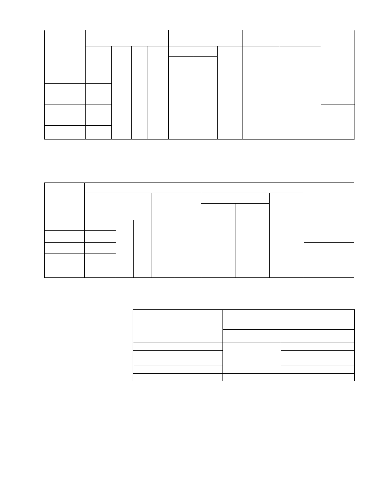
Table-1 Model Chart for Valve (Basic) Actuators.
Timing in Seconds
@ 72 F (22 C)
No Load Stroke Retract
on
Extend Retract
Power
Loss
Required Linkages
Val ve
Applications
Damper
Applications
Part Number
a
Actuator Power Input
AC
Voltage
+10/
Hz VA Watt
-15%
s
MPR-5610 120
MPR-5611 240
MPR-5613 24
MPR-5710
MPR-5711
d
d
120 Compatible
240
50/60 18 10 60 30 15
AV-600
AV-601
c
AM-601
MPR-5713 24
a
These MPR-5X1X series valve actuators are compatible with VB-7XXX 1/2" to 2" valve bodies.
b
The MPR-5X1X series actuators are basic models which may be equipped for damper applications wi h the installation of an AM-601 linkage.
c
May be required for steam and hot water. Refer to Table-3.
d
These actuators are obsolete. They are listed here for reference only.
Table-2 Model Chart for Damper Actuato
rs.
Actuator Power Input Timing in Seconds @ 72 F (22 C)
Part Number
a
AC
Voltage
+10/
-15%
Hz VA Wa
tts
No Load Stroke
Extend Retract
Retract on
Power
Loss
b
Input
Signal
Inpu
t
Signal
Compatible
with
4 to 20 mA
with
135 ¾
Slidewire
(Series 90)
MPR-5630 120
Compatible
with
MPR-5633 24
MPR-5730
b
120 Compatible
50 60 18 10 60 30 15
4 to 20 mA
with
MPR-5733
b
24
135 ¾
Slidewire
(Series 90)
a
Damper models (MPR-5X3X) are provided with factory-installed damper linkages. Only base models (MPR-5X1X) require separately-ordered linkages.
b
These actuators are obsolete. They are listed here for reference only.
Table-3 Restrictions on Maximum Ambient Temperature for Valve Actuators.
Maximum Temperature of Media
in the Valve Body
(Check Rating of the Valve)
F ( C)
366 (186)
340 (171) 93 (34)
281 (138) 103 (39)
181 (83) 120 (48)
80 (26) 140 (60)
a
Maximum ambient temperature of the actuator must never exceed 140 F (60 C).
b
Minimum allowable ambient temperature of he actuators is -20 F (-29 C).
Maximum Ambient Temperature
of MPR-563X and -573X Serie
AV-600 (Only)
F ( C)
Do Not Use
a
s
AV-600 and AV-601
F ( C)
88 (31)
140 (60)
b
a
a
a
F-23576-7 © Copyright 2010 Schneider Electric All Rights Reserved. 3
Page 4
ACCESSORIES
Notes:
1. The 135 Ω controller is supplied by others.
2. The controller has setpoint and throttling range (proportional band) adjustments.
Black
24Vac Black/Blue
120Vac White
240Vac White/Black
To AC Power
Source
MPR-571X or MPR-573X
W
R
B
Temp.
Drop
Controller
135 Ω Slidewire
Yellow/White
Red
Blue
Sequence of operation: As the temperature decreases at the controller, R moves toward
B and the actuator shaft extends. On power loss to the actuator, the shaft retracts.
Green
Notes:
1. The 135 Ω controller is supplied by others.
2. The controller has setpoint and throttling range (proportional band) adjustments.
24Vac Black/Blue
120Vac White
240Vac White/Black
To AC Power
Source
W
R
B
Temp.
Drop
Controller
135 Ω Slidewire
Blue
Red
Yellow/White
Black
MPR-571X or MPR-573X
Sequence of operation: As the temperature decreases at the controller, R moves toward
B and the actuator shaft retracts. On power loss to the actuator, the shaft retracts.
Green
Common
11-1612 1/2" conduit bushing
Damper Linkages
AM-111 Crank arm for 5/16" diameter damper shaft
AM-112 Crank arm for 3/8" diameter damper shaft
AM-113 Crank arm for 1/2" diameter damper shaft
AM-115 Crank arm for 7/16" diameter damper shaft
AM-122 Linkage connector straight type
AM-123 Damper clip
AM-125 5/16" diameter x 20" damper rod
AM-125-048 5/16" diameter x 48" damper rod
AM-132 Ball joint connector
AM-161-3 Damper linkage kit
AM-601 Device includes mounting bracket, da
AM-602 Spacer
Valve Linkages and Valves
AV-600 Valve linkage 1/2" to 1-1/4" (obsolete VB-9XXX)
AV-601 Valve linkage extension for hot water
AV-7600 Valves linkage 1/2" to 2" to be used with VB-7XXX
VB-7XXX 1/2" to 2" valve bodies
VB-9XXX 1/2" to 1-1/4" valve bodies (obsolete)
(factory-available)
TOOLS
TOOL-19 Spring compression tool for AV-600
TOOL-37 1-5/8" open-ended wrench
TOOL-209 135 Ω and 0 to 7 mA manual positioner
straight connector. Requir
(51 mm) stroke damper actuators.
AV-7600
ed to modify (MPR-5X1X series) valve actuators into 2"
mper linkage with spring, and AM-122
and steam applications; use with AV-
600 &
TYPICAL APPLICATIONS (wiring diagrams)
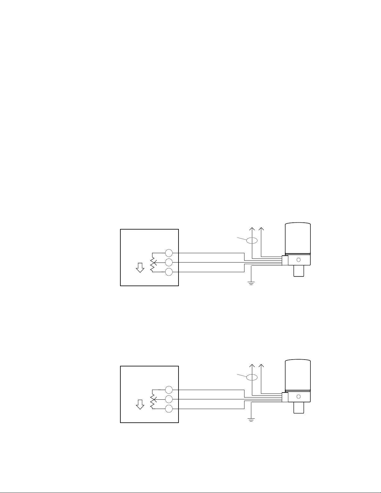
Figure-1 Wiring Diagram - Decrease in Temperature Causes Actuator Shaft to Extend.
4 © Copyright 2010 Schneider Electric All Rights Reserved. F-23576-7
Page 5
Page 6
Page 7
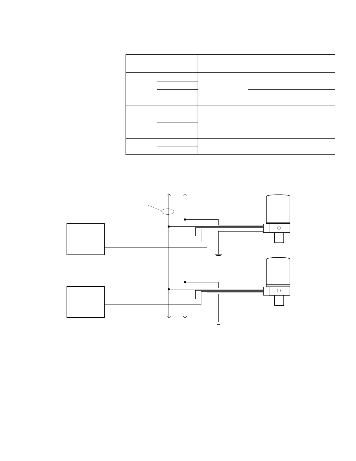
To determine the allowable maximum power lead run when wiring multiple actuators, divide
Black
Green
Green
To Additional MPR-56XX and
MPR-57XX Series Actuators
24Vac Black/Blue
120Vac White
240Vac White/Black
To AC Power
Source
MPR-56XX or MPR-57XX
Yellow/White
Red
Blue
Controller
MPR-56XX or MPR-57XX
Yellow/White
Red
Blue
Controller
the maximum run shown in Table-4 by the number of actuators on the run. Refer to
Figure-5 for further details.
Table-4 Power Wiring Data.
Actuator
Vol tag e
Vac
24
120
240
*Green grounding wire is provided. Length is 4 ft. (1.2 m).
Actuator Model
Number
MPR-5613
MPR-5713
MPR-5633
MPR-5733
MPR-5610
MPR-5710
MPR-5630
MPR-5730
MPR-5611
MPR-5711
Power Lead Colors* Wire Si
Black/Blue & Black
White & Black 14 3,500 (1,067)
White/Black & Black 14 6,000 (1,829)
ze GA
14 300 (91.5)
12 480 (146.3)
Max. Two-Wire Run ft.
(m)
Figure-5 Wiring of Multiple MPR-56XX and MPR-57XX Series Actuators to a Single Power Source.
Wiring Connections General
F-23576-7 © Copyright 2010 Schneider Electric All Rights Reserved. 7
Make connections as required. Refer to the following sections:
• Wire Lead Connections (No Conduit)
• Install 3/8" reduced (thin wall) flexible conduit onto either side of actuator
• Install 3/8" reduced (thin wall) flexible conduit directly onto actuator
• Install conduit box onto actuator
Page 8
Wire Lead Connections (No Conduit)
Base
Knockout
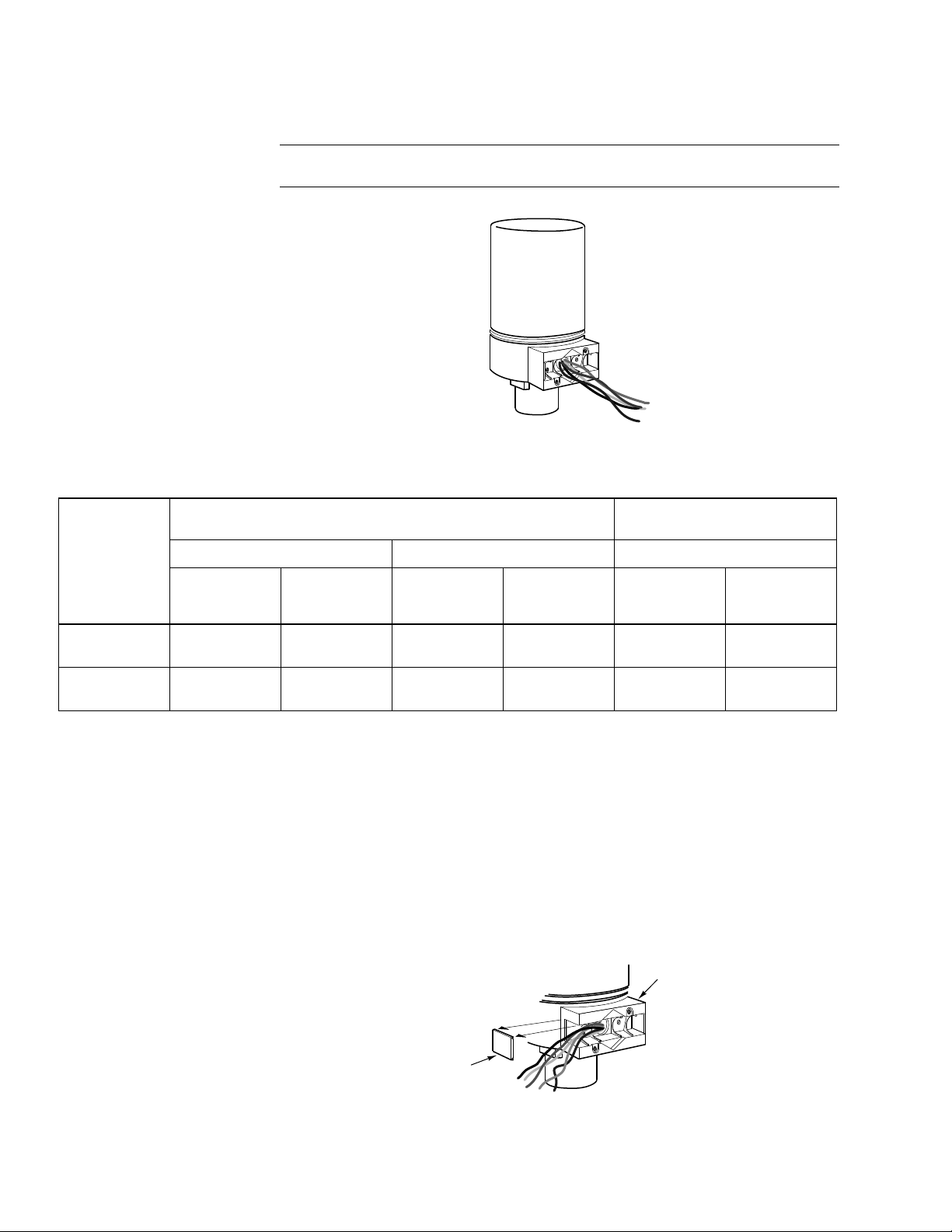
Make connections as required. Refer to Figure-1 through Figure-3 to determine your
particular application. Refer to Ta bl e -5 to determine the damper position versus the input
signal. Refer to Figure-6 for a view of the actuator.
Note: The cover plate and screw supplied with the actuator are not required with this
method.
Table-5 Damper Position Versus Input Signal.
Figure-6 Connection of Wire Leads (No Conduit).
Damper Normal
Position
Normally
Open
Normally
Closed
Decrease
" to "B"
In "R
Resistance
Closes
Damper
Opens
Damper
135 Ω Slidewire (Series 90) Input Signal
Figure-1 Figure-2 Figure-3
MPR-573X Series
Decr
ease
In "R" to "W"
Resistance
Opens
Damper
Closes
Damper
Decrease
In "R" to "B"
Resistance
Opens
Damper
Closes
Damper
Decrease
In "R" to "W"
Resistance
Closes
Damper
Opens
Damper
MPR-563X Serie
4 to 20 mA Input Sig
Decrease
In mA Signal
Opens
Damper
Closes
Damper
s
nal
Increase
In mA Signal
Closes
Damper
Opens
Damper
Installing 3/8" Reduced (thin) Wall Flexible Conduit onto One or Both Sides
of Actuator
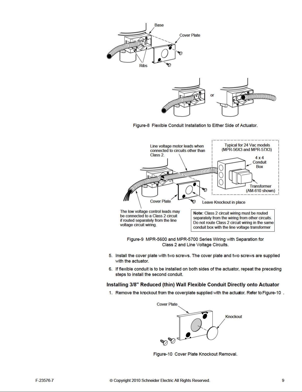
Flexible conduit may be installed onto one or both sides of the actuator (refer to Figure-8
and Figure-9 ). Install each conduit as follows:
1. Determine the side of the actuator to which the flexible conduit is to be att
2. Remove the knockout, using channel lock pliers, on the selected side of the actuator.
Refer to Figure-7 .
3. Make the required connections. Refer to Figure-1 , Figure-2 , and Figure-3 to
determine your particular application. Refer to Table-5 to determine the damper position
versus the input signal.
ached.
Figure-7 Removal of Knockout on Actuator Base.
4. Slip the conduit onto the base, over the ribs. Refer to Figure-8 and
8 © Copyright 2010 Schneider Electric All Rights Reserved. F-23576-7
Figure-9 .
Page 9
Page 10
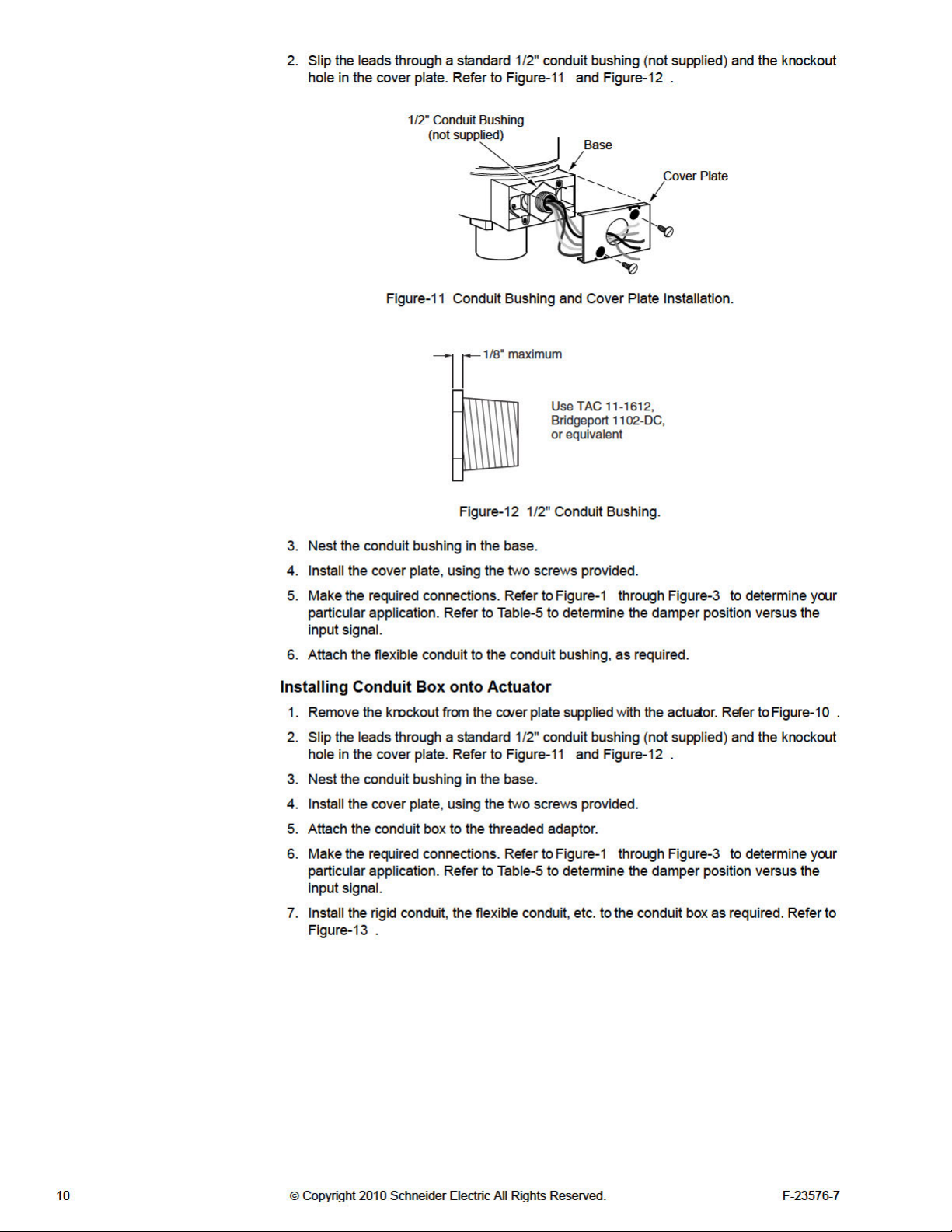
Page 11
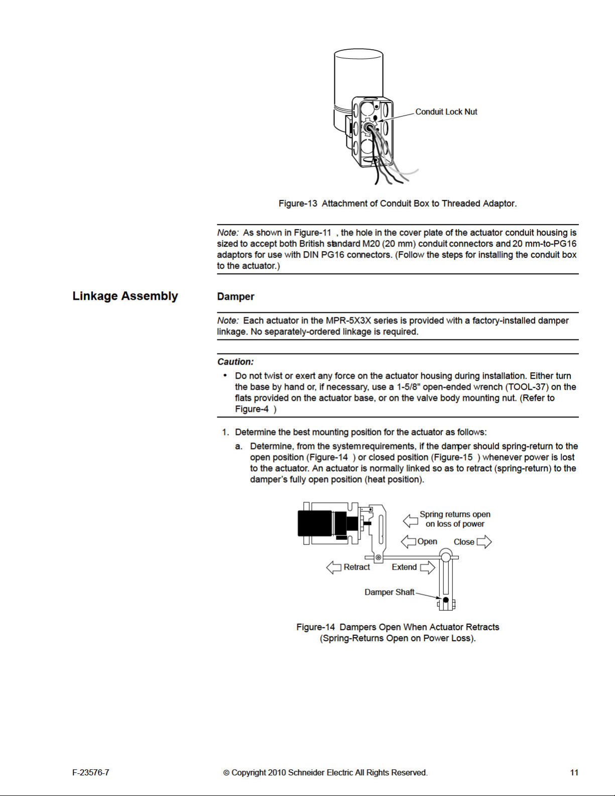
Page 12
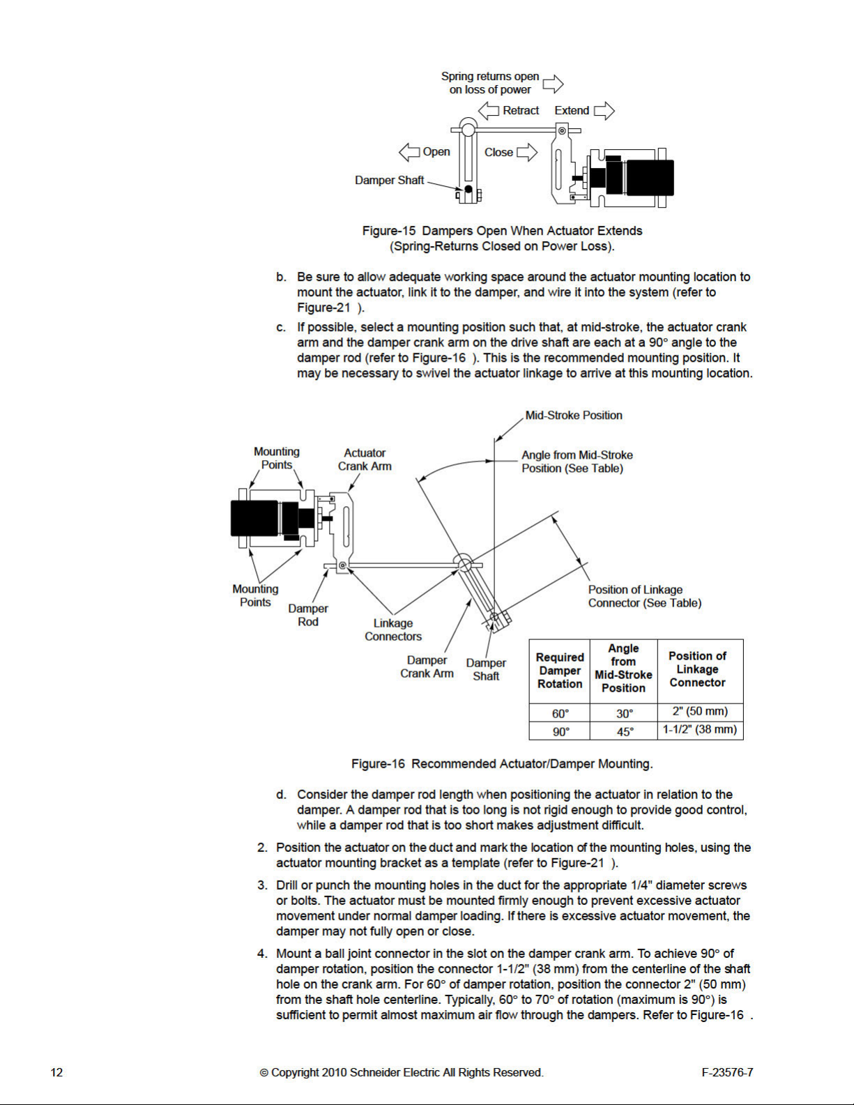
Page 13

5. Rotate the damper to its open position. Install and secure the damper crank arm (with
ball joint connector) to the damper shaft, positioning the crank arm as follows (refer
to Figure-16 ):
a. To achieve 60° of damper rotation, position the crank arm so that it is pointed
towards the actuator at 30° from its mid-stroke position.
b. To achieve 90° of damper rotati
towards the actuator at 45° from its mid-stroke position.
6. Install the damper rod by sliding one end through the ball joint connector mounted on
the damper crank arm, and the other end through the straight connector on the actuator
crank arm. Tighten the nut on the actuator crank arm’s straight connector. Cut off any
excess length of damper rod.
7. For normally open dampers, tighten the nut on the ball joint
crank arm. To ensure that the damper closes completely, make adjustments so that the
actuator is 1/16" (1.6 mm) from the extended end of stroke when the damper
Verify and, if necessary, make final adjustments during system checkout.
8. For normally closed dampers, rotate the damper crank arm until the damper is closed.
While holding the damper closed, tighten the nut on the ball joint connector on the
damper crank arm. To ensure that the damper closes completely, make adjustments so
that the actuator is 1/16" (1.6 mm) from the retracted end of stroke when the damper
.
closes
Final adjustment of the actuator and damper must be performed when the system is
powered and functioning. Refer to the CHECKOUT section to ensure that the damper is
linked correctly.
on, position the crank arm so that it is pointed
connector on the damper
closes.
Valve
For valve assembly details refer to AV-600 Hydraulic Actuator Valve Linkage Kit, F-26279
or AV-601 Linkage Extension Set for AV-600 Valve Linkage Kit, F-26280. Refer to
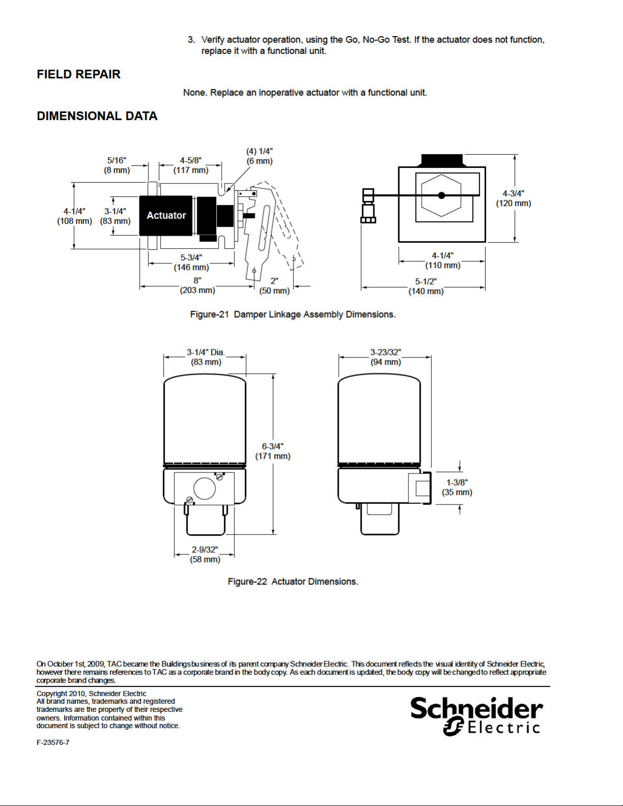
Figure-22 for external dimensions of the valve actuator.
CHECKOUT
Positioning with
Controller
Go, No-Go Test
(MPR-57XX Series
Only)
Manual Positioning
(MPR-57XX Series
Only)
After the entire system has been installed and the actuator has been powered up, perform
the following checks for proper system operation.
Caution: Never power the actuator without a spring return linkage attached.
If the sensed media is within the controller’s setpoint range, the actuator can be positioned
by adjusting the controller setpoint up and down. Check for correct operation of the actuator
(valve or damper) while the actuator is being stroked.
1. Apply power to the actuator.
2. Disconnect the actuator’s control leads from the controller.
3. Make the actuator shaft extend fully by shorting the red lead to the blue lead.
4. Make the actuator shaft retract fully by shorting the red lead to
5. Check for proper operation of the valve or damper as the actuator is operated
6. Reconnect the actuator wires to the controller.
7. Remove power from the actuator.
1. Apply power to the actuator.
2. Disconnect the actuator’s control leads from the controller.
3. Attach the slidewire leads from the calibration box (TOOL-209) to
on the actuator.
4. Manually position the actuator by turning the knob of the calibration box (TOOL-209).
Turning the knob in the clockwise direction retracts the actuator shaft. Turning the knob
in the counterclockwise direction extends the actuator shaft.
5. Check for proper operation of the valve or damper as the actuator is operated.
the yellow/white lead.
.
the same-color leads
F-23576-7 © Copyright 2010 Schneider Electric All Rights Reserved. 13
Page 14
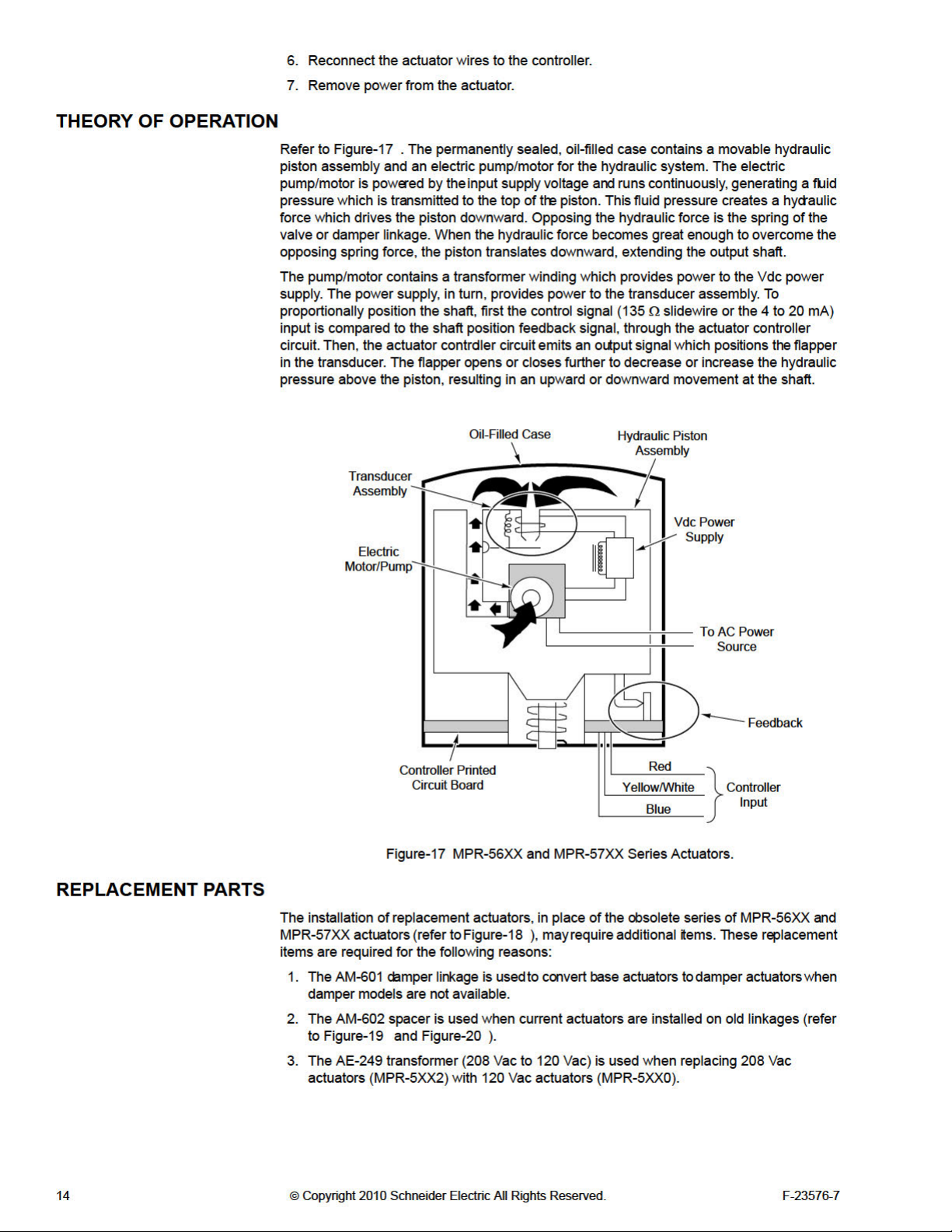
Page 15
Page 16
 Loading...