

Page 1

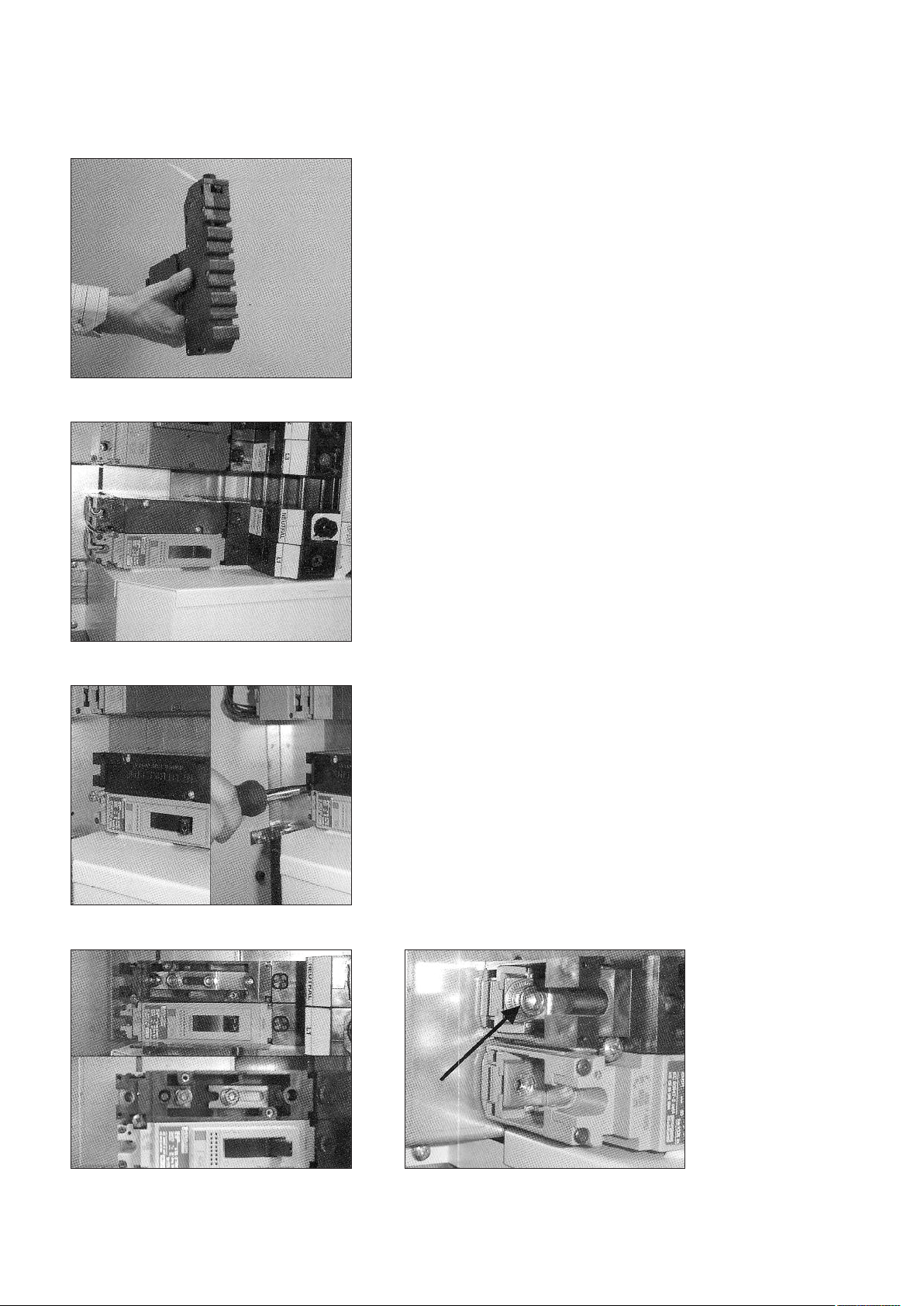
Fig 1
Fig 2
Panelboard MCCB connection system
Installation instructions
To allow installation of the Compact NSX MCCB into the Powerpact
4 panel board, a factory fitted connector is added to the MCCB
(Fig 1). The connector is normally fitted to the “top” of the circuit
reaker. The exception to this is main incoming breakers for top
b
entry 630A boards, when the connector is fitted to the “bottom”.
This instruction leaflet details the connector.
Snap-off feature
When the correct tightening torque is reached the top half of the
terminal screw breaks off leaving just the bottom portion. It is
important to ensure that the 17mm ring spanner or A/F socket used
does not turn both the top and bottom of the terminal screw as this
would prevent the top portion from snapping off.
The bottom portion that is left behind can be used in the event that
the MCCB is changed or more often during routine maintenance
when checking for tightness of all electrical joints.
Installation
a Tighten shear head bolts on cassette using a 17mm A/F socket
or ring spanner (Fig 2).
b The top half of the hexagon head will shear off (Fig 3) when the
required tightening torque (20Nm for 250A and 28Nm for
400A/630A) is reached.
Note: Prepare yourself for this action and ensure you do
not slip when the bolt head shears off.
For removing or refitting a device with sheared off bolts use a 17mm
12 point socket. Retighten connections to 20Nm for 250A and
28Nm for 400/630A breakers.
Note:
For single pole and double pole breakers the connector determines
the phase that the breaker is connected to (i.e. MGP1001L1 suitable to connect to the L1 phase).
Fig 3
Health & Safety at Work, etc Act 1974
To ensure that the equipment described is safe for both personnel and property it should be installed, commissioned and maintained by or
under the supervision of qualified persons. Regard should be taken of BS7671, Codes of practice, statutory requirements and any specific
instructions issued by Schneider Electric. Any operating or installation queries relatingto these products should be communicated
directly to Schneider Electric.
Schneider Electric Limited,
Stafford Park 5, Telford, TF3 3BL
Tel: 0870 608 8 608 Fax: 0870 608 8 606
Internet address: www.schneider-electric.co.uk
Page 2
Document No. 1287301X
Panelboard neutral link 250/630A
Installation instructions
A neutral link can be fitted on an outgoing circuit alongside a single
pole or triple pole circuit breaker.
ssembly
A
When purchased the neutral link is supplied fitted with a connector,
ready to be fitted into the panelboard. It can be fitted to the left or
the right hand side of the outgoing circuit breaker that it is
associated with. We recommend mounting to the left for
consistency.
Fig 1
Fig 2
Installation
a Remove the front cover from the panelboard by loosening the 4
captive screws.
b Check the jaws on the connector, ensure that they are fully
open (Fig 1).
c Align neutral link into position on the outgoing tray (Fig 2) and
secure with the screw provided. This screw has a captive
washer/clamp (Fig 3a & b).
d Tighten shear head bolt, using a 17mm A/F socket or ring
spanner. The top half of the hexagon will shear off when the
correct tightening torque is reached (20Nm for 250A and 28Nm
for 400/630A). Torque tolerances are 5%. (See Panelboard
MCCB connection system)
Note: prepare yourself to ensure this does not cause you to slip.
e Isolation of Neutral Link
To isolate the neutral link remove the cover from the top of the
link. Slacken both nuts using a socket spanner, slide the copper
connection to disconnect (Fig 4).
f Reconnection of Neutral Link
For reconnection, reverse the process. The 250A neutral link
M6 nuts are tightened to 6Nm. The 630A neutral link M8 nuts
are tightened to 8Nm.
g Refit and secure cover with 2 screws provided.
h Tighten cable terminal connections (Fig 5). For 250A tighten M8
cap screw to 15Nm and 630A tighten M10 cap screw to 50Nm.
i Blank any unused ways using blanking plates.
j Refit the front cover of the panelboard and tighten screws.
Fig 3a
Fig 3b
Fig 4 Fig 5
 Loading...