

Page 1
APPLICATION
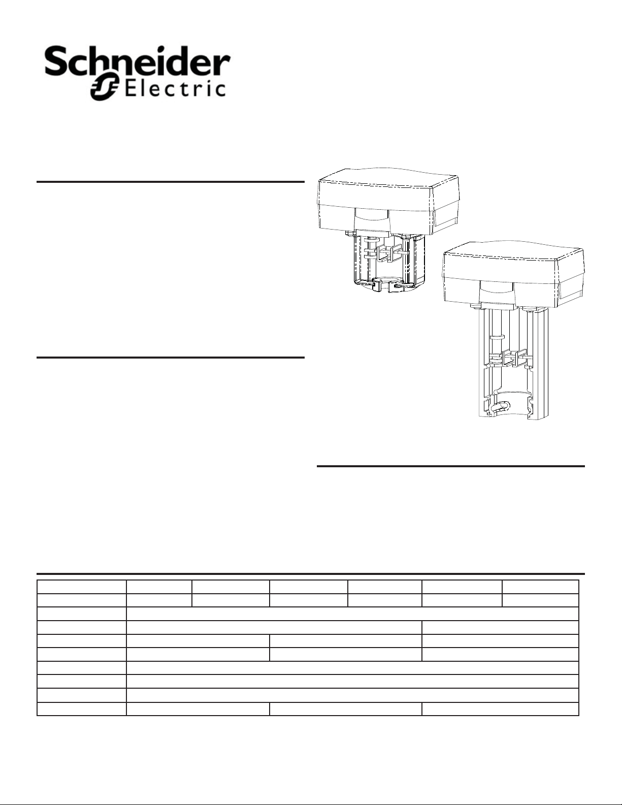
Forta M400A (VB) / M800A (VB) /M1500A (VB) series Non-Spring Return linear actuators are available in two styles, U-Bolt Mount style,
mounts to Schneider Electric globe valves with AV-821 linkage kits
for mounting to VB-7xxx valves or AV-822 for mounting to VB-8xxx,
or VB-9313-0-5-xx valves. Screw Mount style, screws directly to the
bonnet nut on VB-7xxx valves (no adapter required).
Applications include chilled or hot water and steam. Field selectable input signals include reverse and direct acting, Floating or
Proportional 0-10, 2- 10 vdc or 4-20 ma with 500 ohm resistor
(supplied) plus proportional sequencing input signal ranges.
M400A (VB), M800A (VB), M1500A (VB)
Schneider Electric Non-Spring Return
Forta Globe Valve
Actuators and Assemblies
General Instructions
FEATURES
Two Mounting Styles, U-Bolt Mx00A or Screw Mx00A-VB •
Floating con guration controlled by a SPDT oating controllers•
Proportional con guration 0-10, 2-10 vdc or 4-20 mA with the •
addition of a 500 ohm resistor included
Direct/Reverse action switch selectable•
90 lbf (400N) linear force•
180 lbf (800N) linear force•
Screw Mount Style Forta (Left) and U-Bolt Style Forta (Right)
337 lbf (1500N) linear force•
24 Vac • or 24 Vdc Powered
APPLICABLE LITERATURE
Die-cast housing with plenum rated plastic cover for NEMA 2 •
(IP54 vertical mount only) applications
Manual override to allow positioning of valve•
Electronic valve sequencing and Electronic ow curve (equal •
percentage or Linear) selection.
Torque overload protection throughout stroke•
Easy “One Touch” input signal/stroke calibration•
Forta/VB-7xxx Selection Guide, F-27490•
Forta/VB-8xxx, VB-9xxx Selection Guide, F-27491•
AV-800 Series Linkage Adapters for Competitors Valves, F-27470•
AV-821 Linkage VB-7xxx, F-27701- U-Bolt Style Only•
AV-822 Linkage VB-8xxx, VB-9xxx, F-27702 U-Bolt Style Only•
SPECIFICATIONS
U-bolt Style M400A M400A-S2 M800A M800A-S2 M1500A M1500A-S2
Screw Mount Style M400A-VB M400A-S2-VB M800A-VB M800A-S2-VB M1500A-VB M1500A-S2-VB
AC Power
DC Power
Running VA
Transformer Size VA
Floating Control
Proportional Control
Feedback
Force
20 - 29 Vdc 20 W 20 - 29 Vdc 30 W
6
30
0 to 10 Vdc, 2 to 10 Vdc or 4 to 20mA with 500 ohm resistor
90 lbf (400 N)
24 Vac +- 10% 50-60 Hz
15
50
Yes
2 to 10 Vdc
180 lbf (800 N)
24
50
337 lbf (1500 N)
F-27599-4 Copyright 2011 Schneider Electric All Rights Reserved. 1
Page 2
Forta
Globe Valve Actuators & Assemblies
SPECIFICATIONS CONTINUED
Stroke
M800, M1500
2
U-Bolt style: >3/8” to 2” (9-52mm)
M800-VB, M1500 VB
M400, M400-VB
Stroke Timing
Feedback AO
Power Supply Type
Motor Type
Enclosure
Sound Power Level
Ambient Temperature Storage
Ambient Temperature
Operational
Minimum Operating Temperature
Ambient Humidity
Housing Material
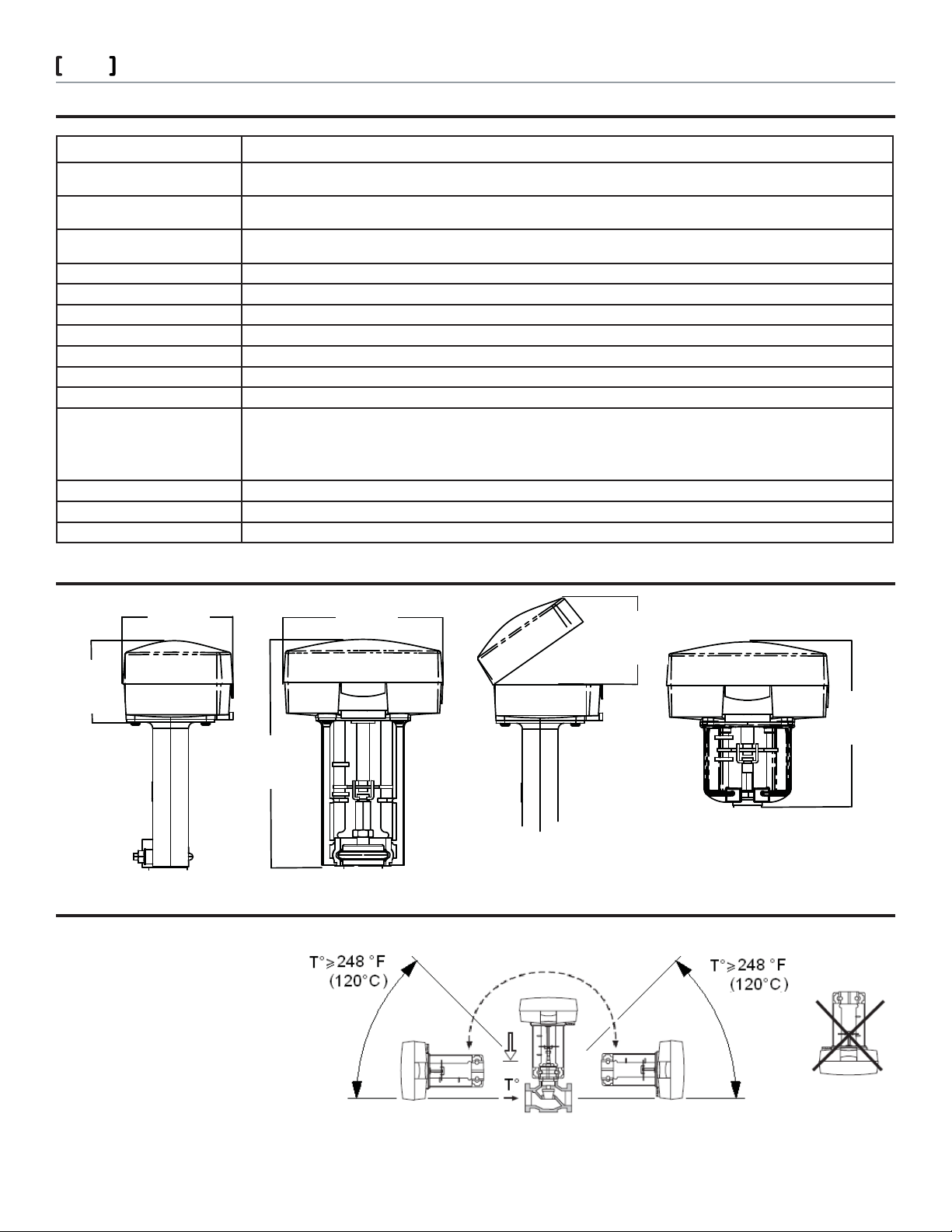
DIMENSIONS
4.60”
(117 mm)
Screw Mount Style >3/8” to 1 7/8” (9-48mm)
U-Bolt and Screw Mount Style >3/8” to 1 1/4” (9-48mm)
Floating: 60 or 300 sec selectable, Proportional: 15 sec @1/2” stroke
2 to 10 Vdc
Half Wave
Brushless DC
NEMA 2 (IP 54, vertical mount only) with both conduit connectors used. NEMA 1 IP40 with one connector used.
Maximum 32 dba
-13 °F to 149 °F (-25 to 65 °C) ambient
122 °F (50 °C) For chilled water applications
113 °F (45°C) ambient at 281 °F (138°C) uid temperature
107 °F (42 °C) ambient at 300 °F (149 °C) uid temperature
100 °F (38 °C) ambient at 340 °F (171°C) uid temperature
90°F (32°C) ambient at 366 °F (186 °C) uid temperature
14 ° to 150 ° F (-10 ° to 50 ° C)
15 to 95 % RH non-condensing
Die-Cast Aluminum
6.31”
(173 mm)
3” *
(79 mm)
3.235”
(82 mm)
6.38”
(132 mm)
9.53”
(242 mm)
Screw Mount
*3” (76mm) clearance above actuator recommended
to remove actuator
Tall U-Bolt Style
MOUNTING
The actuator may be mounted
horizontally, vertically and in any position in between, but not upside down,
Please note that to maintain NEMA
2 (IP54) rating the actuator must be
mounted vertical.
Schneider Electric 13 5 4 C lif for d Av e. L o ve s P ark , I L 61111 1- 88 8 - 4 4 4-13 11 w w w. s c hne i d er- e l ect r i c.c o m / bui ldi n g s
F-27599-4 March 2011 co
© 2011 Schneider Electric. All rights reserved.
Page 3
Forta
Globe Valve Actuators & Assemblies
FUNCTION
The actuator
The brushless DC-motor of the actuator turns a screw via a gear wheel. When the motor
receives a control signal from the controller, the screw moves in a linear motion, moving the
stem of the valve.
Control signal
The M400A (VB)/ M800A (VB)/ M1500A (VB) Series can be controlled by a SPDT oating
control, Triac source controller or a proportional input signal.
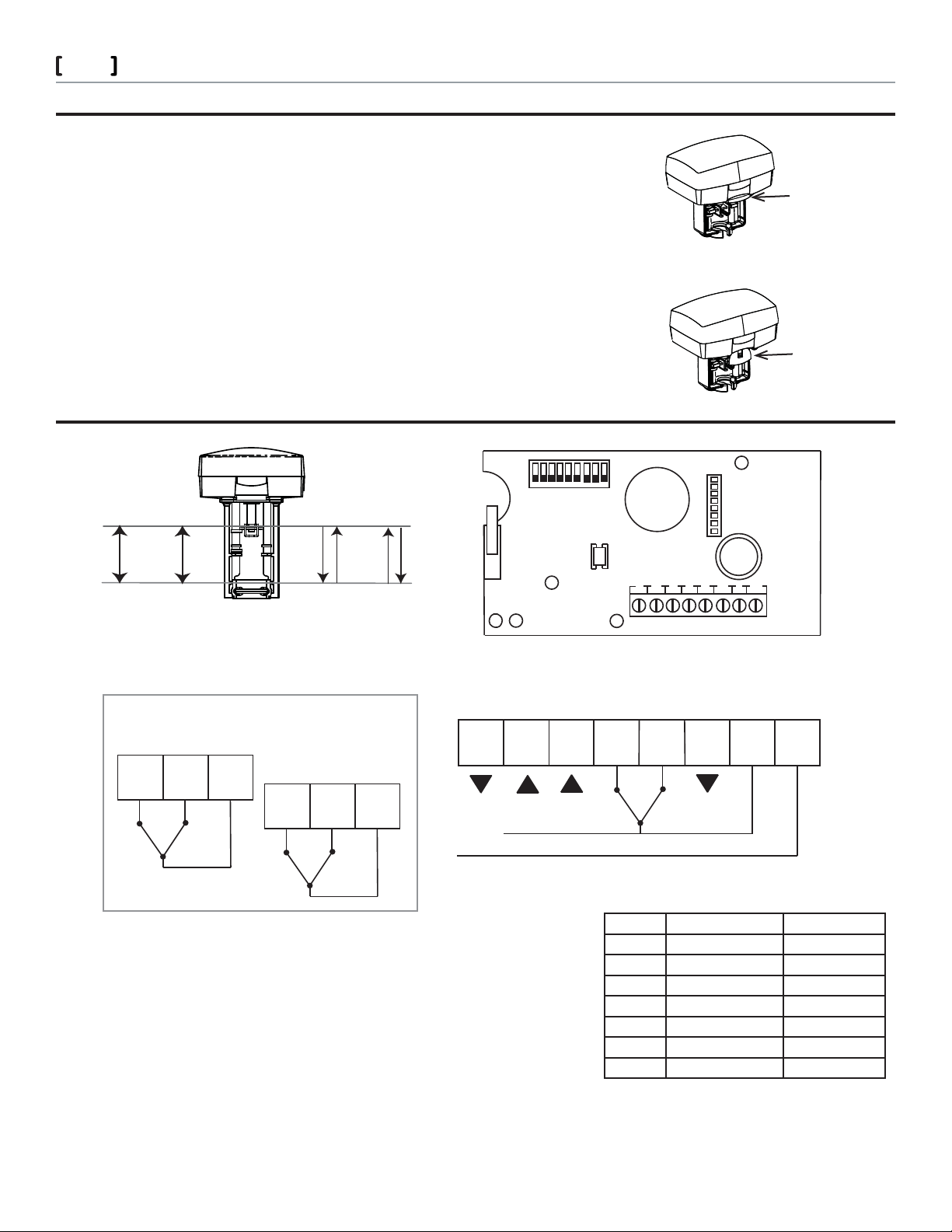
Manual operation
There is a red manual operation handle on the actuator. When it is lowered, the motor stops.
Then the actuator can be operated manually if the handle is turned.
Note: Actuator is shipped with manual override lowered (MAN). For normal operating, the
handle must be raised (AUTO).
Position feedback
M400A (VB), M800A (VB), and M1500A (VB) actuators are equipped with a 2-10 Vdc position feedback.
CONNECTIONS
456789
3
2
1
3
Red Manual
Override Lever-
Raised (Auto)
Red Manual
Override Lever-
Lowered (Manual)
NORM
0(2)V
10V
AI D1D2 D1D2
INV
10V
0(2)V
AI
NORM
Optional Auxiliary Switch Outputs S2
Relay 1
K3
Relay 2
K4 KC2
K1
K2 KC1
INV
A0
A1
A0 AI C D1 D2 G H
*
C
D2 G
D1
H
24 Vac
* Provides 16 Vdc, 25 mA output source
Note: For oating input signals the cables between the controller and the Forta should not
exceed 328’ (100m) (16 AWG) with the cables connected to one actuator. When installed
with 3 conductors with very long lengths ( oating control), where control signal reference is connected to G, the motor current of the actuator will cause varying voltage loss in
the cable and thus in the reference level. Forta which has a highly sensitive control signal
input, will detect the varying signal and follow it, which makes it di cult for the actuator
to nd a stable position.
Cable Lengths: The wires to G, H should be max of 328 ft (100m). min AWG 16, all other
proportional input signal input wires should be a max of 656 ft (200m) min AWG 20.
Please refer to the Wiring Examples for wiring instructions.
Schneider Electric 13 5 4 C lif for d Av e. L o ve s P ark , I L 61111 1- 88 8 - 4 4 4-13 11 w w w. s c hne i d er- e l ect r i c.c o m / bui ldi n g s
F-27599-4 March 2011 co
Block Function Description
G
24 Vac or 24 Vdc Com
H
AI
C
D1
D2
AO
** Exact Operation will vary based on the settings of
DIP switch #1 and #7.
24 Vac or +24 Vdc
+
-
Floating
Floating
+
Power
Power
Input Signal
Signal Common
Extend/Retract**
Extend/Retract**
Feedback Signal
© 2011 Schneider Electric. All rights reserved.
Page 4
Forta
Globe Valve Actuators & Assemblies
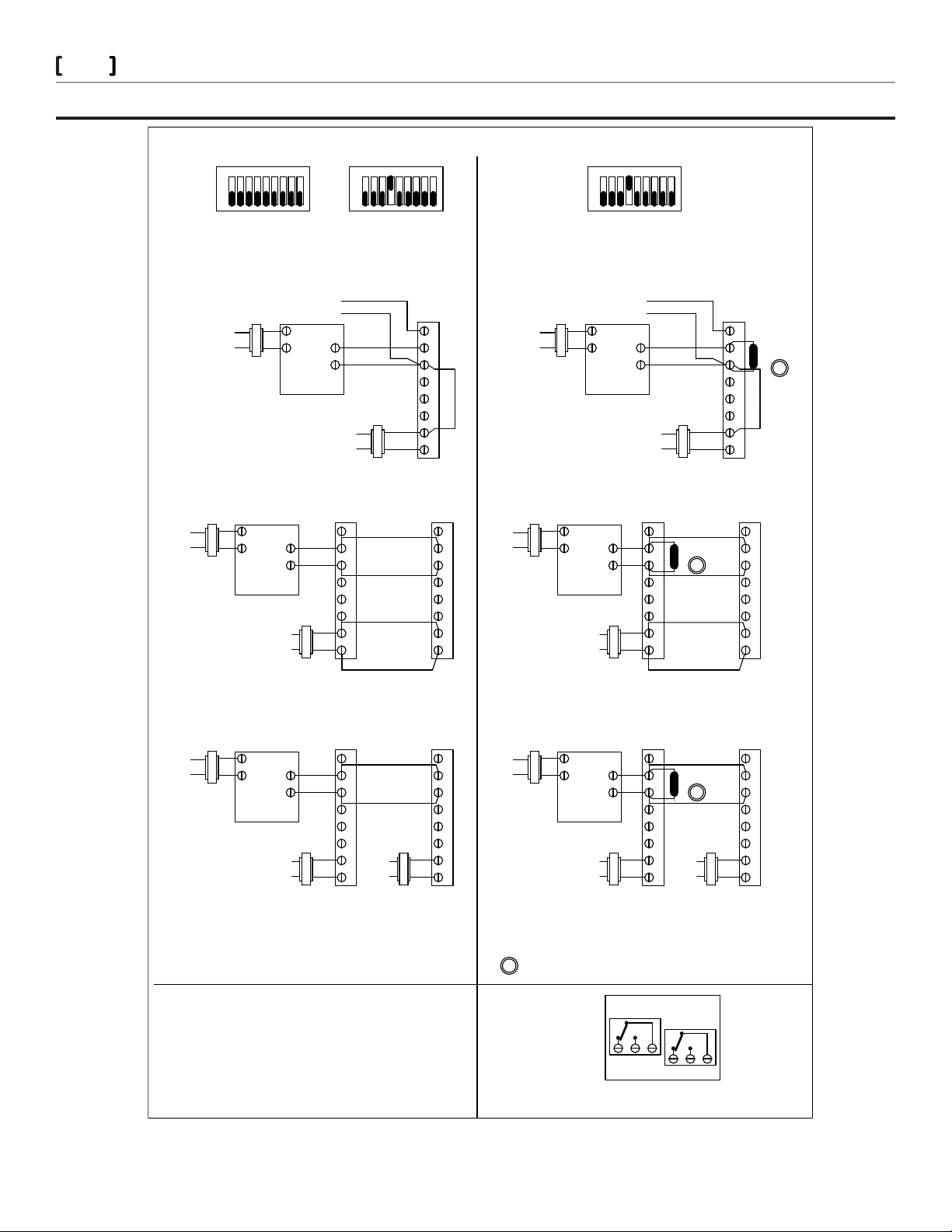
WIRING EXAMPLES
PROPORTIONAL CONTROL WIRING DIAGRAMS
12 43 65798
312 456 879
4
98ON7645231
OFF ON
Switches 2 & 4 OFF
0-10V
Proportional operation Proportional operation
TRANSFORMER OR DC POWER SUPPLY TO BE SIZED FOR RECOMMENDED VA
REQUIREMENTS PER CONTROLLER/ACTUATOR PRODUCT DATA SHEETS
2-10 Vdc
Feedback
H
G
Controller
Line
Volts
Transformer
OFF ON
Switches 2 OFF & 4 ON
2-10V
+
-
Transformer or
DC Power Supply
Line
Volts
Actuator
0-10/2-10 Vdc Proportional Application
* Provides 16 Vdc, 25mA output source
** Optional Ground connection ** Optional Ground connection
Line
Volts
Transformer
H
G
Controller
+
-
Transformer or
DC Power Supply
Line
Volts
Actuator
AO
AI D1C
D2
*
HG
D1 HGD2CAIAO
*
Actuator
OFF
Switches 2 OFF & 4 ON
4-20mA with 500 ohm resistor
Proportional operation
TRANSFORMER OR DC POWER SUPPLY TO BE SIZED FOR RECOMMENDED VA
REQUIREMENTS PER CONTROLLER/ACTUATOR PRODUCT DATA SHEETS
2-10 Vdc
Transformer
Line
Volts
*
*
Feedback
H
G
Controller
+
-
Line
Volts
Transformer or
DC Power Supply
Actuator
500 ohm
A
*
*
*
HGD2D1CAIAO
4-20mA Proportional Application
* Provides 16 Vdc, 25mA output source
ActuatorTransformer
Line
AI D1CAO
Volts
D2
*
HG
H
G
Controller
Transformer or
DC Power Supply
Line
Volts
+
-
AO
AI D1C
500ohm
D2
*
HG
Actuator
AI D1CAO
A
*
HGD2
0-10/2-10Vdc Proportional Multiple
Actuators powered from single source.
* Provides 16 Vdc, 25mA output source
Transformer
Line
Volts
H
G
Controller
0-10/2-10Vdc Proportional Multiple
Actuators powered from separate sources.
+
-
Transformer or
DC Power Supply
Line
Volts
Actuator
*
HGD2D1CAIAO
Line
Volts
Transformer or
DC Power Supply
Actuator
Transformer
Line
AI CAO
Volts
D1 D2
*
HG
4-20mA Proportional Multiple
Actuators powered from single source.
* Provides 16 Vdc, 25mA output source
Actuator
H
+
G
-
Controller
Transformer or
DC Power Supply
Line
Volts
4-20mA Proportional Multiple
AO
*
HGD2D1CAI
500ohm
Line
Volts
Transformer or
DC Power Supply
Actuators powered from separate sources.
Actuator
A
*
GD2D1CAIAO
H
* Provides 16 Vdc, 25mA output source * Provides 16 Vdc, 25mA output source
500 ohm resistor (included w/actuator) is required.
A
For 4-20mA input Dip Switches 2 OFF and 4 ON
Caution: This product contains a half-wave rectier power
supply and must not be powered o transformers used to
power other devices utilizing non-isolated full-wave rectier
power supplies.
Refer to EN-205, Guidelines for Powering Multiple Devices from
a Common Transformer, F-26363 for detailed information
Relay 1
Relay 2
KC1K1 K2
KC2K3 K4
OPTIONAL S2 AUXILIARY SWITCH
Schneider Electric 13 5 4 C lif for d Av e. L o ve s P ark , I L 61111 1- 88 8 - 4 4 4-13 11 w w w. s c hne i d er- e l ect r i c.c o m / bui ldi n g s
F-27599-4 March 2011 co
© 2011 Schneider Electric. All rights reserved.
Page 5
Forta
Globe Valve Actuators & Assemblies
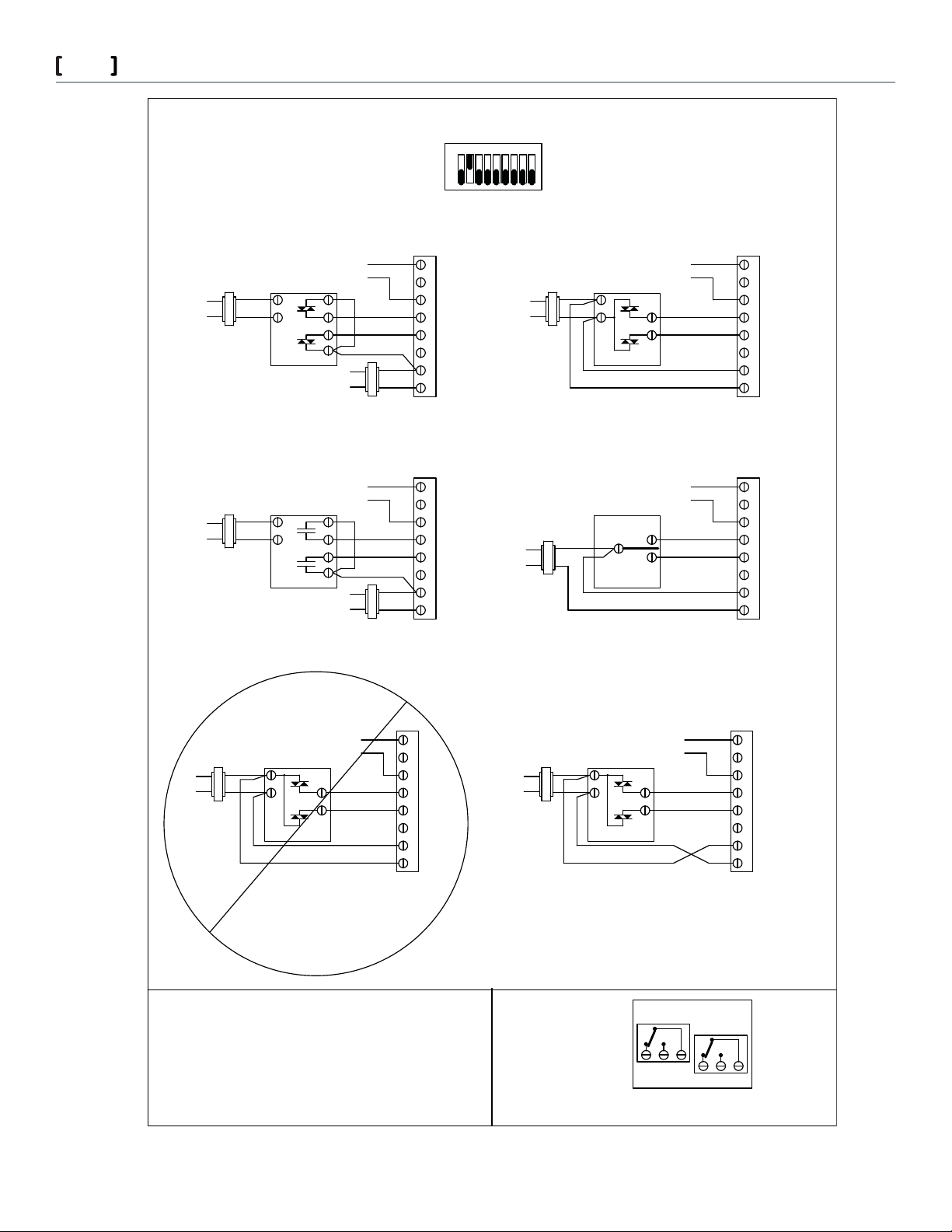
FLOATING CONTROL WIRING DIAGRAMS
TRANSFORMER OR DC POWER SUPPLY TO BE SIZED FOR RECOMMENDED VA REQUIREMENTS
2-10 Vdc
Feedback
Line
Volts
Transformer
98ON7645231
OFF
Switch 2 ON for oating operation
PER CONTROLLER/ACTUATOR PRODUCT DATA SHEETS
Actuator
Transformer
D1 HGD2CAIAO
Line
Volts
5
Actuator
2-10 Vdc
Feedback
H
C
Line
Volts
Line
Volts
Controller
TRIAC SINK Application
* Provides 16 Vdc, 25mA output source
Transformer
* Provides 16 Vdc, 25mA output source
Transformer
Two power sources
Controller
RELAY SINK Application
Two power sources
H
C
Line
Volts
Transformer / DC Power Supply
2-10 Vdc
Feedback
Line
Volts
Transformer / DC Power Supply
Actuator
2-10 Vdc
Feedback
Actuator
*
D1CAIAO
D2 HG
*
Transformer / Power Supply
Line
Volts
Transformer
Line
Volts
Controller
TRIAC SINK Application
* Provides 16 Vdc, 25mA output source
* Provides 16 Vdc, 25mA output source
One power source
2-10 Vdc
Feedback
Controller
RELAY SINK Application
One power source
2-10 Vdc
Feedback
H
C
*
HGD2D1CAIAO
Actuator
CAIAO
*
GD2D1
H
Actuator
Controller
TRIAC SOURCE Application
* Provides 16 Vdc, 25mA output source
One power source
*
HGD2D1CAIAO
Controller
TRIAC SOURCE Application
* Provides 16 Vdc, 25mA output source
One power source
*
HGD2D1CAIAO
DO NOT WIRE AS SHOWN
Note:
If AC polarity cannot be determined, a
separate transformer must power each
Relay 1
Relay 2
KC1K1 K2
KC2K3 K4
controller and actuator.
OPTIONAL S2 AUXILIARY SWITCH
Schneider Electric 13 5 4 C lif for d Av e. L o ve s P ark , I L 61111 1- 88 8 - 4 4 4-13 11 w w w. s c hne i d er- e l ect r i c.c o m / bui ldi n g s
F-27599-4 March 2011 co
© 2011 Schneider Electric. All rights reserved.
Page 6
Forta
Globe Valve Actuators & Assemblies
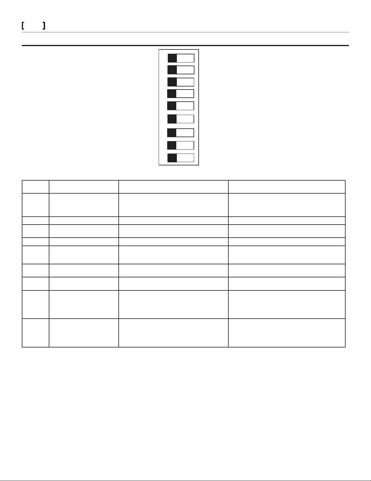
PROGRAM SWITCH SETTINGS FOR THE FORTA NONSPRING RETURN ACTUATORS
6
1
IN
Proportional
2
3
4
0-10
56
0-5, 2-6
60 sec.
Normal
Normal
7
8
9
OP ADJ
OFF
Switch Set-
ting
1 Valve closing screw direction After power up, actuator will retract fully before the
2 Control mode
3 Sequence operation
4 Input voltage range
5 Working voltage range
6 Running time
7 Direction of movement This switch will change the proportional or oating input
8 Linearization
9 Input signal/ Stroke Calibration Normal Used to calibrate the input control signal and the valve
1 Units are shipped with all nine switches in a default “o ” position.
2 Switch 3 must be in the o position if sequence control is not used.
3 Switch 5 is only active if switch 2 is o and switch 3 is on.
Description O Position
input control signal takes control. This switch will change
the proportional or oating input signal to direct or
reverse action similar to switch 7.
Proportional signal Floating signal
2
3
( oating control only)
signal to direct or reverse action similar to switch 1.
Normal operation SW 2 o , SW 3 on, SW 4 select base range (0-10 or 2-10) SW 5
0 to 10 Vdc 2 to 10 Vdc
0 to 5 Vdc
or
2 to 6 Vdc
60 sec 300 sec
Normal
1
OUT
Floating
Sequence
2-10
5-10, 6-10
300 sec.
Inverse
LIN/LG
ON
On Position
After power up, actuator will extend fully before the input
control signal takes control. This switch will change the
proportional or oating input signal to direct or reverse action
similar to switch 7.
select sequence range
5 to 10 Vdc
or
6 to 10 Vdc
This switch will change the proportional or oating input
signal to direct or reverse action similar to switch 1.
Used to adjust the actuator’s linear or logarithmic characteris-
tics. With this setting, the characteristics of an equally modi-
ed percentage valve can be modi ed to almost linear and
a linear valve can operate with “quick open” characteristics
based on the application requirements.
stroke. With the actuator powered, turn switch nine on, then
o . The actuator will match the control input signal to the
valve stroke. Note: Switch 9 must be in the o position for
normal operation.
Note: For the actuator to register new settings of the switches, the supply voltage must be removed by cutting power to the actuator or
lowering the manual override lever, then change any of switches one through eight as required and then restore power to the actuator or
raise the manual override level.
Schneider Electric 13 5 4 C lif for d Av e. L o ve s P ark , I L 61111 1- 88 8 - 4 4 4-13 11 w w w. s c hne i d er- e l ect r i c.c o m / bui ldi n g s
F-27599-4 March 2011 co
© 2011 Schneider Electric. All rights reserved.
Page 7
Forta
Globe Valve Actuators & Assemblies
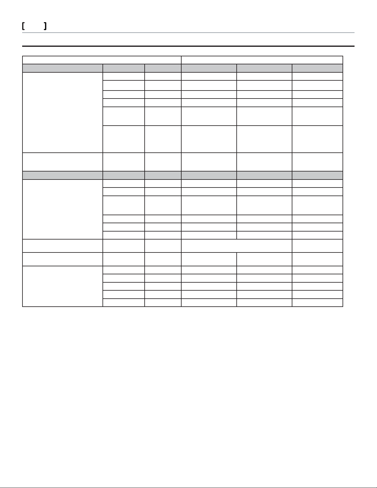
ACTUATOR VALVE SELECTION FOR THE FORTA NONSPRING RETURN ACTUATORS
Select Valve/Actuator Combination Having Su cient Close o for Application
Valve Body
Two-Way Valves P Code Size M400A ( VB) M800A (VB) M1500A (VB)
VB-7211-0-3-P
VB-7211-0-4-P
VB-7212-0-4-P
VB-7213-0-4-P
VB-7214-0-4-P
VB-7215-0-4-P
VB-7221-0-4-P
VB-7222-0-4-P
VB-7223-0-4-P
VB-7224-0-4-P
VB-7225-0-4-P
VB-7253-0-4-P
VB-7263-0-4-P
VB-7273-0-4-P
VB-7283-0-4-P
VB-8213-0-5-P
VB-8223-0-5-P
Three-Way Valves P Code Size M400A ( VB) M800A (VB) M1500A
VB-7312-0-4-P
VB-7313-0-4-P
VB-7314-0-4-P
VB-7315-0-4-P
b
b
a
-01, -02, -03, -04 1/2”(15 mm) 250 (1712) 250 (1712) —
-05, -06 3/4” (20 mm) 198 (1356) 250 (1712) —
-07, -08 1” (25 mm) 92 (630) 207 (1418) —
-09 1-1/4” (32 mm) 56 (384) 130 (890) —
-10 1-1/2” (40 mm) 37 (253) 88 (603) 177 (1212)
-11 2” (40 mm) 19 (130) 48 (329) 98 (671)
-12, -13, -14, -15,
-16
-02, -04 1/2”(15 mm) 250 (1712) 250 (1712) —
-06 3/4” (20 mm) 198 (1356) 250 (1712) —
-08 1” (25 mm) 92 (630) 207 (1418) —
2-1/2” to 6” Do not use Do not use 125 (856)
Close-o Ratings, psi (kPa)
7
VB-7323-0-4-P -04, -06, -08, -09,
VB-8303-0-5-P
VB-9313-0-5-P
b
b
-12, -13, -14, -15,
a. Not all bodies are available for all port codes.
b. Requires U-Bolt mounting style.
-09 1-1/4” (32 mm) 56 (384) 130 (890) —
-10 1-1/2” (40 mm) 37 (253) 88 (603) —
-11 2” (40 mm) 19 (130) 48 (329) —
-10, -11
-16
-12 2-1/2” Do not use
-13 3” Do not use
-14 4” Do not use
-15 5” Do not use Do not use 14 (96)
-16 6” Do not use Do not use 9 (62)
1/2” to 2” 250 (1712) Do not use
2-1/2” to 6” Do not use Do not use 35 (241)
29 (199)
19 (130)
10 (68)
61 (418)
42 (288)
22 (151)
Schneider Electric 13 5 4 C lif for d Av e. L o ve s P ark , I L 61111 1- 88 8 - 4 4 4-13 11 w w w. s c hne i d er- e l ect r i c.c o m / bui ldi n g s
F-27599-4 March 2011 co
© 2011 Schneider Electric. All rights reserved.
Page 8
Forta
Globe Valve Actuators & Assemblies
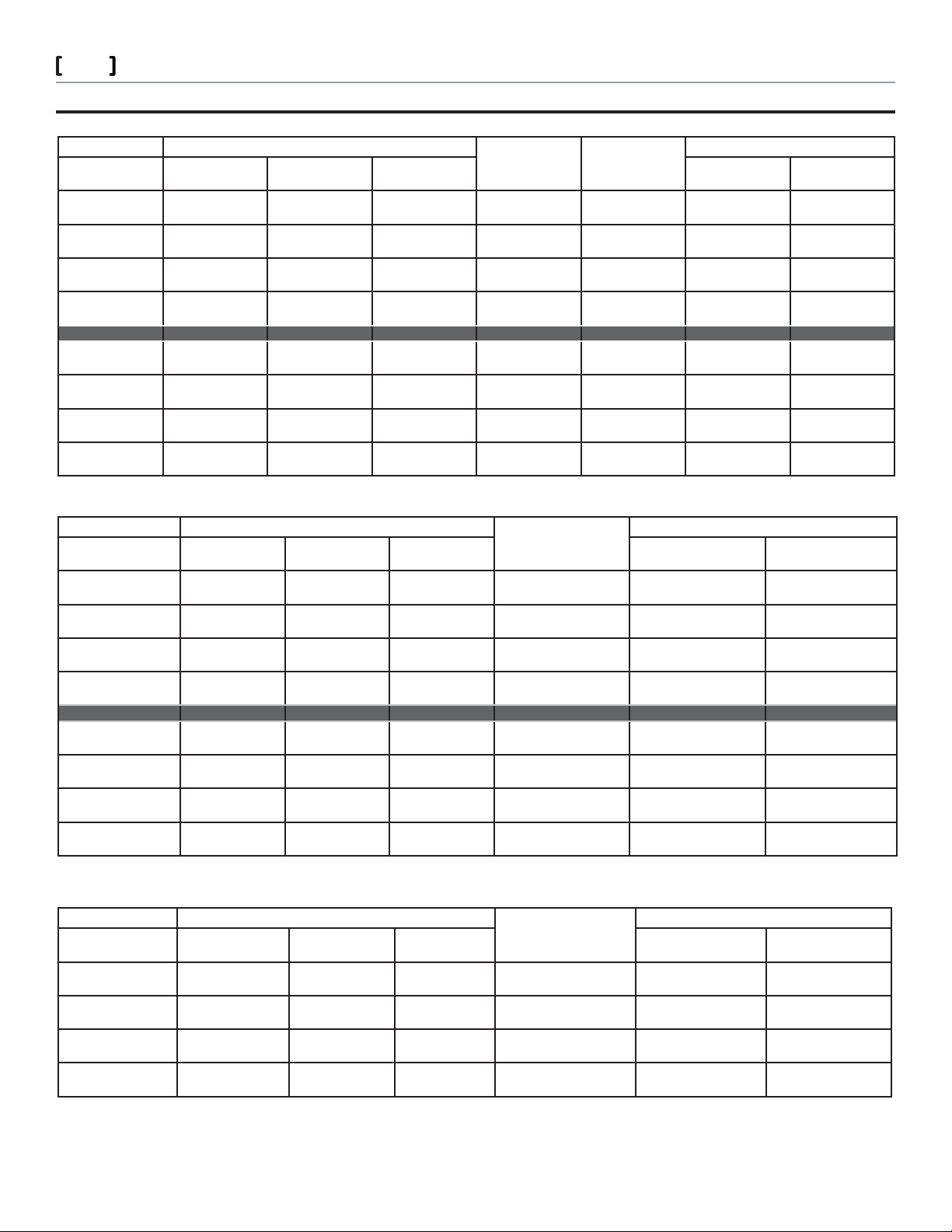
PROGRAMMING FORTA NONSPRING RETURN ACTUATORS
VB 72x3 and 82x3 Two-Way Globe Valve, Forta Non-Spring Return, Proportional Control Setup Reference
Valve Type Program Switch Position Power Up
Valve position at
low signal input
VB-x223 stem up
closed
VB-x223 stem
down open
VB-x223 stem up
closed
VB-x223 stem
down open
Switch 1 Switch 2 Switch 7 Low end of signal
OFF OFF OFF Retract No Flow DA Retract No Flow 2 Vdc No Flow
OFF OFF ON Retract No Flow RA Extend Full Flow 10 Vdc Full Flow
ON OFF ON Extend Full Flow DA Retract No Flow 10 Vdc No Flow
ON OFF OFF Extend Full Flow RA Extend Full Flow 2 Vdc Full Flow
Position
Input Signal Action Desired Valve Operation
a
input range
8
Feedback Signal
Action
10 Vdc Full Flow
2 Vdc No Flow
2 Vdc Full Flow
10 Vdc No Flow
VB-x213 stem up
open
VB-x213 stem
down closed
VB-x213 stem up
open
VB-x213 stem
down closed
ON OFF ON Extend No Flow RA Retract Full Flow 10 Vdc Full Flow
ON OFF OFF Extend No Flow DA Extend No Flow 2 Vdc No Flow
OFF OFF OFF Retract Full Flow RA Retract Full Flow 2 Vdc Full Flow
OFF OFF ON Retract Full Flow DA Extend No Flow 10 Vdc No Flow
VB-73x3 or VB-9313 Three-Way Globe Valve, Forta Non-Spring Return, Proportional Control Setup Reference
Valve Type Program Switch Position Power Up Position
Valve position at low
signal input
VB-x313 stem up
Open B to AB
VB-x313 stem down
Closed B to AB
VB-x313 stem up
Open B to AB
VB-x313 stem down
Closed B to AB
VB-7323 stem up
ow B to AB
VB-7323 stem down
ow B to A
VB-7323 stem up
ow B to AB
VB-7323 stem down
ow B to A
Switch 1 Switch 2 Switch 7 Low end of signal input
OFF OFF OFF Retract-Full Flow
OFF OFF ON Retract-Full Flow
ON OFF ON Extend-Full Flow
ON OFF OFF Extend-Full Flow
OFF OFF OFF Retract-Full Flow
OFF OFF ON Retract-Full Flow
ON OFF ON Extend-Full Flow
ON OFF OFF Extend-Full Flow
B to AB
B to AB
A to AB
A to AB
B to AB
B to AB
B to A
B to A
a
Retract-Full Flow
Extend-No Flow
Retract-Full Flow
Extend-No Flow
Retract-Full Flow
Extend-No Flow
Retract-Full Flow
Extend-No Flow
a. Upon power up, actuator will stroke to the power up position before the input signal takes control.
Desired Valve Operation
range
B to AB
B to AB
B to AB
B to AB
B to AB
B to AB
B to AB
B to AB
2 Vdc No Flow
10 Vdc Full Flow
10 Vdc No Flow
2 Vdc Full Flow
Feedback Signal Action
at Port B
2 Vdc Full Flow
10 Vdc No Flow
10 Vdc No Flow
2 Vdc Full Flow
10 Vdc Full Flow
2 Vdc No Flow
2 Vdc No Flow
10 Vdc Full Flow
2 Vdc Full Flow
10 Vdc No Flow
10 Vdc No Flow
2 Vdc Full Flow
10 Vdc Full Flow
2 Vdc No Flow
2 Vdc No Flow
10 Vdc Full Flow
VB-8303 Three Way Globe Valve, Forta Non-Spring Return, Proportional Control Setup Reference
Valve Type Program Switch Position Power up
Valve position with
D2 powered
VB-8303 stem up
Open B to AB
VB-8303 stem down
Closed B to AB
VB-8303 stem up
Open B to AB
VB-8303 stem down
Closed B to AB
Switch 1 Switch 2 Switch 7 Low end of signal input
OFF OFF OFF Retract-Full Flow
OFF OFF ON Retract-Full Flow
ON OFF ON Extend-Full Flow
ON OFF OFF Extend-Full Flow
position
B to AB
B to AB
A to AB
A to AB
a
Desired Valve Operation
range
Retract-Full Flow
B to AB
Extend-No Flow
B to AB
Retract-Full Flow
B to AB
Extend-No Flow
B to AB
Feedback signal action
@ Port B
2 Vdc Full Flow
10 Vdc No Flow
10 Vdc No Flow
2 Vdc Full Flow
10 Vdc Full Flow
2 Vdc No Flow
2 Vdc No Flow
10 Vdc Full Flow
a. Upon power up, actuator will stroke to the power up position before the input signal takes control.
Schneider Electric 13 5 4 C lif for d Av e. L o ve s P ark , I L 61111 1- 88 8 - 4 4 4-13 11 w w w. s c hne i d er- e l ect r i c.c o m / bui ldi n g s
F-27599-4 March 2011 co
© 2011 Schneider Electric. All rights reserved.
Page 9
Forta
Globe Valve Actuators & Assemblies
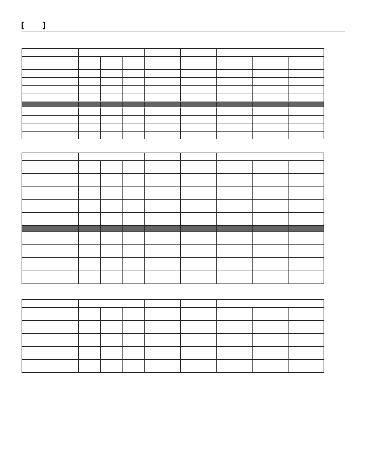
VB-72x3 or VB-82x3 Two Way Globe Valve, Forta Non-Spring Return, Floating Control Setup Reference
Valve Type Program Switch Position Desired Valve Operations
Valve position with D2
powered
VB-x223 stem up closed OFF ON OFF Retract-No Flow Retract-No Flow 2 Vdc Extend-Full Flow 10 Vdc
VB-x223 stem down open OFF ON ON Retract-No Flow Extend-Full Flow 10 Vdc Retract-No Flow 2 Vdc
VB-x223 stem up closed ON ON ON Extend-Full Flow Retract-No Flow 10 Vdc Extend-Full Flow 2 Vdc
VB-x223 stem down open ON ON OFF Extend-Full Flow Extend-Full Flow 2 Vdc Retract-No Flow 10 Vdc
VB-x213 stem up open ON ON ON Extend-No Flow Retract-Full Flow 10 Vdc Extend-No Flow 2 Vdc
VB-x213 stem down closed ON ON OFF Extend-No Flow Extend-No Flow 2 Vdc Retract-Full Flow 10 Vdc
VB-x213 stem up open OFF ON OFF Retract-Full Flow Retract-Full Flow 2 Vdc Extend-No Flow 10 Vdc
VB-x213 stem down closed OFF ON ON Retract-Full Flow Extend-No Flow 10 Vdc Retract-Full Flow 2 Vdc
Switch 1 Switch 2 Switch 7 Power up
position
a
Power to D2
input terminal
Feedback signal Power to D1
input terminal
Feedback signal
VB-73x3 or VB-9313 Three Way Globe Valve, Forta Non-Spring Return, Floating Control Setup Reference
Valve Type Program Switch Position Desired Valve Operations
Valve position with D2
powered
VB-x313 stem up
Open B to AB
VB-x313 stem down
Closed B to AB
VB-x313 stem up
Open B to AB
VB-x313 stem down
Closed B to AB
Switch 1 Switch 2 Switch 7 Power up
position
OFF ON OFF Retract-Full Flow
B to AB
OFF ON ON Retract-Full Flow
B to AB
ON ON OFF Extend-Full Flow
A to AB
ON ON ON Extend-Full Flow
A to AB
a
Power to D2
input terminal
Retract-Full Flow
B to AB
Extend-No Flow
B to AB
Extend-No Flow
B to AB
Retract-Full Flow
B to AB
Feedback signal Power to D1
input terminal
2 Vdc Ex tend-No Flow
B to AB
10 Vdc Retract-Full Flow
B to AB
2 Vdc Retract-Full Flow
B to AB
10 Vdc Ex tend-No Flow
B to AB
Feedback signal
9
10 Vdc
2 Vdc
10 Vdc
2 Vdc
VB-7323 stem up
Flow B to AB
VB-7323 stem down
Flow B to A
VB-7323 stem up
Flow B to AB
VB-7323 stem down
Flow B to A
OFF ON OFF Retract-Full Flow
B to AB
OFF ON ON Retract-Full Flow
B to AB
ON ON OFF Extend-Full Flow
B to A
ON ON ON Extend-Full Flow
B to A
Retract-Full Flow
B to AB
Extend-No Flow
B to AB
Extend-No Flow
B to AB
Retract-Full Flow
B to AB
2 Vdc Ex tend-No Flow
B to AB
10 Vdc Retract-Full Flow
B to AB
2 Vdc Retract-Full Flow
B to AB
10 Vdc Ex tend-No Flow
B to AB
10 Vdc
2 Vdc
10 Vdc
2 Vdc
VB-8303 Three Way Globe Valve, Forta Non-Spring Return, Floating Control Setup Reference
Valve Type Program Switch Position Desired Valve Operations
Valve position with D2
powered
VB-8303 stem up
Open B to AB
VB-8303 stem down
Closed B to AB
VB-8303 stem up
Open B to AB
VB-8303 stem down
Closed B to AB
Switch 1 Switch 2 Switch 7 Power up
position
OFF ON OFF Retract-Full Flow
B to AB
OFF ON ON Retract-Full Flow
B to AB
ON ON OFF Extend-Full Flow
A to AB
ON ON ON Extend-Full Flow
A to AB
a
Power to D2
input terminal
Retract-Full Flow
B to AB
Extend-No Flow
B to AB
Extend-No Flow
B to AB
Retract-Full Flow
B to AB
Feedback signal Power to D1
input terminal
2 Vdc Ex tend-No Flow
B to AB
10 Vdc Retract-Full Flow
B to AB
2 Vdc Retract-Full Flow
B to AB
10 Vdc Ex tend-No Flow
B to AB
Feedback signal
10 Vdc
2 Vdc
10 Vdc
2 Vdc
a. Upon power up, actuator will stroke to the power up position before the input signal takes control.
Note: The switch positions on pages eight and nine are the base programming con gurations, in the base con gurations all other switches
should be switched o . Once the base programming con guration has been set up you may wish to add additional programming features
and functions that are listed below.
DA = Full open, full ow, 10vdc output / Full closed, no ow, 2vdc output
RA = Full open, full ow, 2vdc output / Full closed, no ow 10vdc output
Schneider Electric 13 5 4 C lif for d Av e. L o ve s P ark , I L 61111 1- 88 8 - 4 4 4-13 11 w w w. s c hne i d er- e l ect r i c.c o m / bui ldi n g s
F-27599-4 March 2011 co
© 2011 Schneider Electric. All rights reserved.
Page 10
Forta
Globe Valve Actuators & Assemblies
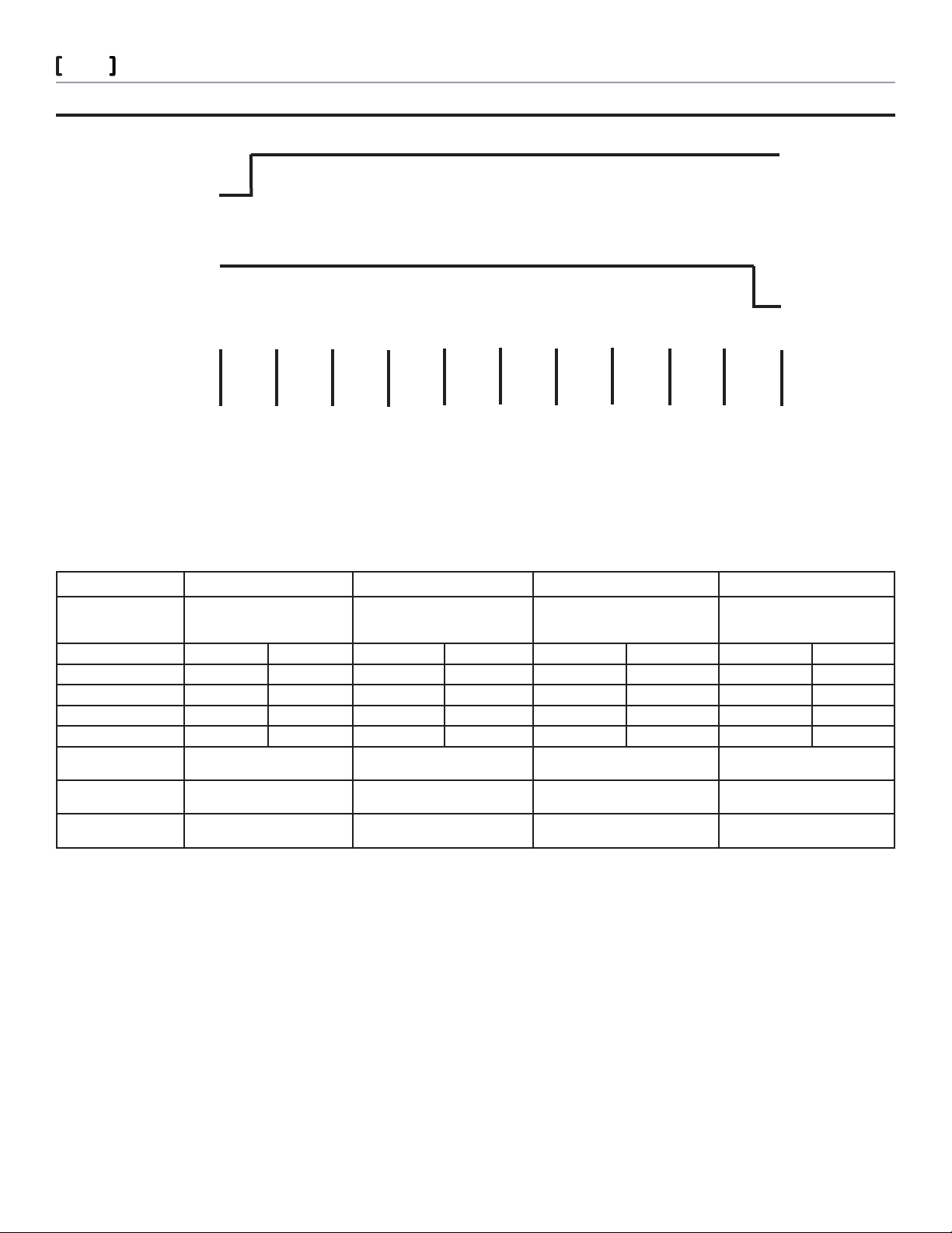
AUXILIARY SWITCH SETUP
10
Switch 1
CLOSE
OPEN
CLOSE
Switch 2
OPEN
% of Value Travel
With the actuator powered and being controlled by the input signal the optional auxiliary switches only transfer contacts as
follows, driving from full retract to full extend the auxiliary contacts transfer when the actuator is about 95% of full extend travel.
When the actuator drives from full extend to full retract the contacts will transfer when the actuator is about 95% of full retract travel.
Optional Auxiliary Switch Function (S2)
Auxliary Switches
2- SPDT
KC1-K1 X X X X
KC1-K2 X X X X
KC2-K3 X X X X
KC2-K4 X X X X
Floating Control or
Proportional Control
High Input Signal or
D1 Action
Low Input Signal or
D2 Action
0
Example A Example B Example C Example D
Program Switch 1 OFF
Powered
Retracted
Closed Open Closed Open Closed Open Closed Open
Program switches 1 o , 7 o Program switches 1 on, 7 on Program switches 1 o , 7 on Program switches 1 on, 7 o
Extends Extends Retracts Retracts
Retracts Retracts Extends Extends
10 20
30 40
Program Switch 1 ON
Powered
Extended
50
60 70 80 90 100
Program Switch 1 OFF
Powered
Retracted
Program Switch 1 ON
Powered
Extended
Note: This table shows the auxiliary switch action based on the dip switch 1 and 7 settings. You should program the dip switches on the
actuator based on the application requirements, once programmed review this chart to determine the action of the auxiliary switches and
wire the switches accordingly. IF YOU CHANGE EITHER DIP SWITCH 1 or 7 TO GET A DIFFERENT CONTACT CLOSURE YOU WILL
CHANGE THE EXTEND/RETRACT MOVEMENT OF THE ACTUATOR.
Schneider Electric 13 5 4 C lif for d Av e. L o ve s P ark , I L 61111 1- 88 8 - 4 4 4-13 11 w w w. s c hne i d er- e l ect r i c.c o m / bui ldi n g s
F-27599-4 March 2011 co
© 2011 Schneider Electric. All rights reserved.
Page 11
Forta
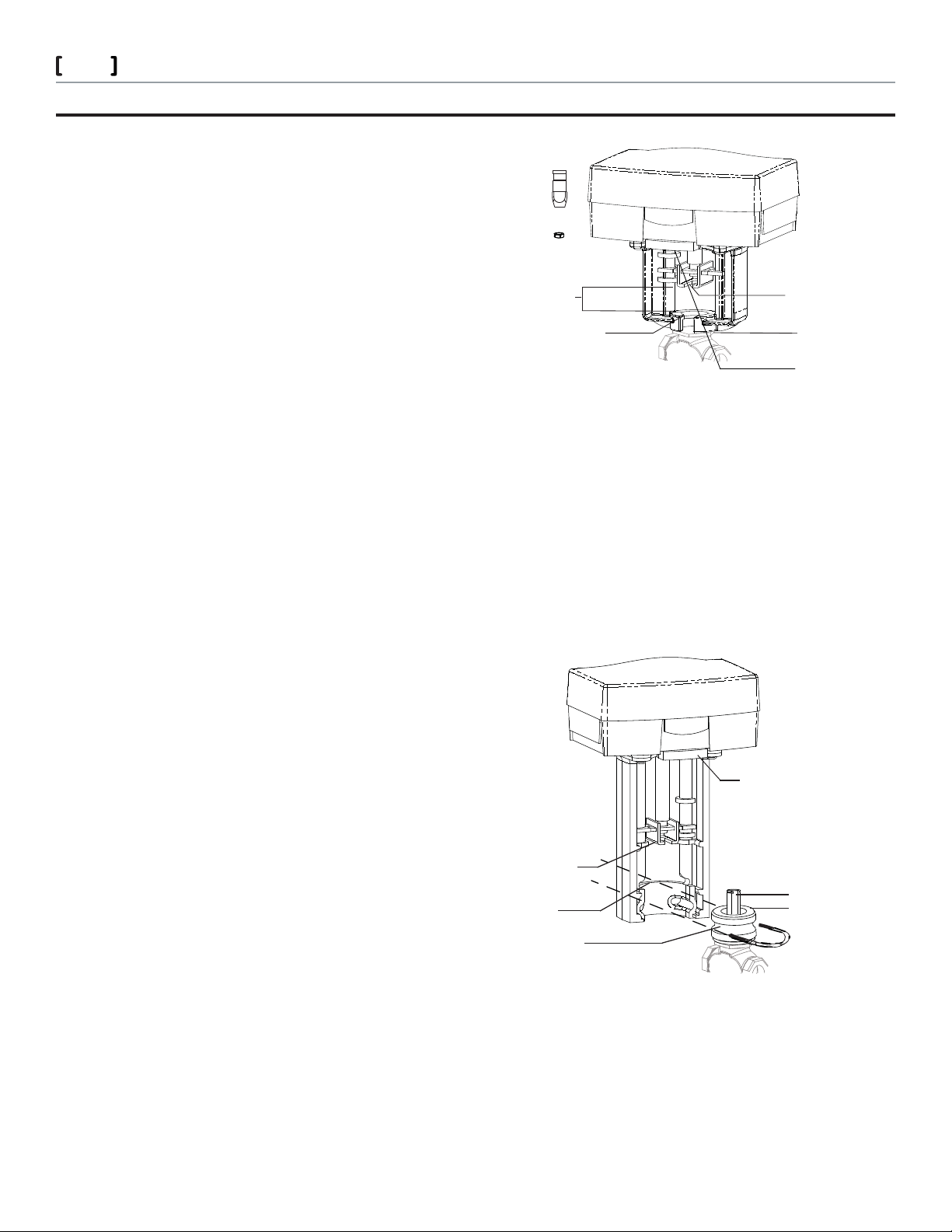
Screw-Mount Forta
Actuator Linkage Slot
Stem Adaptor
Actuator Stem Height
Valve Nut
Top of the Actuator Yoke Slot
Red Manual Override Lever
Shown in Auto Position
Note: Clockwise and Counter-Clockwise directional orientation in the installation instruction is
described from the underside of the actuator, not from the view above.
Stem Nut
Globe Valve Actuators & Assemblies
ACTUATOR INSTALLATION
Short, Threaded Forta Valves Installation on a 1/2” - 2” VB-7000: Valve
Installation
Required Tools:
M-370 1 5/8” open end wrench
7/16” open end wrench
5/16” open end wrench
Con rm that the factory set dimension from the bottom of the 1.
actuator linkage slot to the top of the mounting boss is 7/8”. If
the actuator is not set at this dimension please adjust the actuator to obtain this 7/8” dimension by placing the Red Manual
Override Lever in the down position and rotating it to obtain
required position.
Pull up the valve stem.2.
Screw the stem adapter jam nut (provided with the actuator) to 3.
the bottom of the valve stem threads.
Screw the stem adapter (provided with the actuator) all the way 4.
on to the valve stem to the jam nut, using the 5/16” and 7/16”
open end wrenches and tighten.
Slide the groove of the stem adapter in to the actuator linkage 5.
slot and position the actuator on to the valve.
Engage the large valve nut several turns on to the actuator yoke 6.
by hand (the valve stem may be pushed into the valve during
this process).
To create plug and seat clearance before nal assembly tightening, lower the Red Manual Override Lever and rotate clockwise
ve turns (looking from the bottom of the actuator). If you skip
this step, you may have trouble getting the valve tight onto the
actuator and risk damaging internal components of the valve.
Fully tighten the large valve nut to the actuator yoke using the 7.
M-370 1 5/8” open end wrench.
Raise the Red Manual Override Lever to allow actuator operation.8.
11
U-Bolt Mount (Tall) Forta: Valve Installation
½” – 2” VB-7000
AV-821 (Purchase Separately)
Required Tools:
M-370 1 5/8” open end wrench
7/16” open end wrench
5/16” open end wrench
13 mm wrench
Con rm that the factory set dimension from the bottom of the 1.
actuator linkage slot to the top of the mounting boss is 2 1/4”.
If the actuator is not set at this dimension please adjust the
actuator to obtain this 2 1/4” dimension with the Red Manual
Override Lever in the down position turn as required. Raise
Red Manual Override Lever after re-positioning.
Pull up the valve stem.2.
Screw the stem adapter jam nut, provided with the AV-82x, 3.
1/2” down the valve stem threads.
Screw the stem adapter, provided with the AV-82x kit, on to 4.
the valve stem to the jam nut, tighten with wrenches.
Install the AV-82x bonnet adapter all the way on the valve, and 5.
tighten with appropriate wrenches.
Slide the goove of the stem adapter in to the actuator linkage 6.
slot and position the actuator onto the valve aligning the
grove of the bonnet adapter with the U-Bolt mounting holes
in the actuator yoke.
7. Install the U clamp and the two 13mm U clamp mounting nuts
and tighten with the 13mm wrench.
Schneider Electric 13 5 4 C lif for d Av e. L o ve s P ark , I L 61111 1- 88 8 - 4 4 4-13 11 w w w. s c hne i d er- e l ect r i c.c o m / bui ldi n g s
F-27599-4 March 2011 co
2 ½” – 6” VB-8000/9313
AV-822 (Purchase Separately)
Required Tools:
3/4” open end wrench
5/8” open end wrench
13 mm wrench
Pipe wrench
Bottom of the
actuator linkage slot
Top of the
mounting boss
Bonnet adapter
Red Manual Override Lever
Shown in Auto Position
Stem adapter
Jam nut
U-Bolt Forta mounted on VB-7000 valve
© 2011 Schneider Electric. All rights reserved.
Page 12
Forta
Globe Valve Actuators & Assemblies
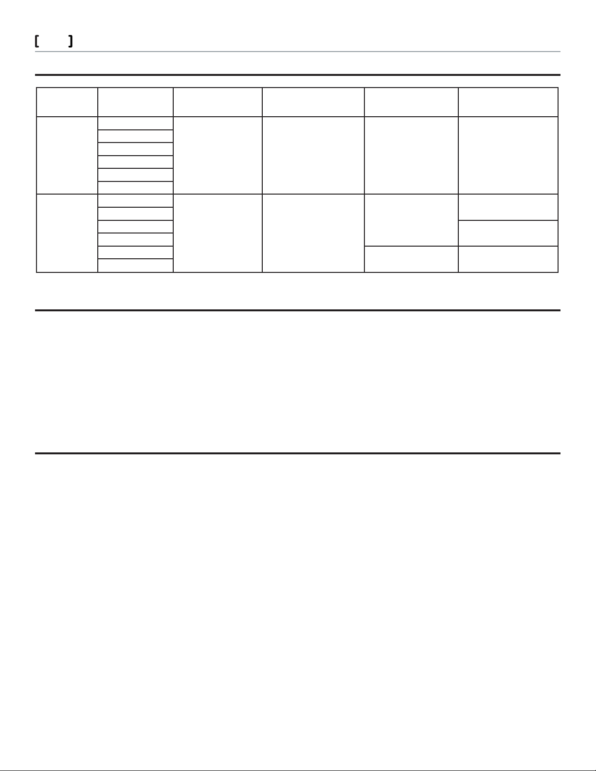
GLOBE VALVE/FORTA COMPATIBILITY
12
Connection Part Number VB-7000 1/2 “ to 2” Bronze
Screw-Mount M400A-VB
M400A-S2-VB
M800A-VB
M800A-S2-VB
M1500A-VB
M1500A-S2-VB
U-Bolt Mount M400A
M400A-S2
M800A
M800A-S2
M1500A
M1500A-S2
Direct Mounted
a
Yes
—Yes
VB-7000 1/2” to 2” Bronze Re-
quires AV-821 Linkage
Purchased separately
———
a
VB-8000 2-1/2” to 6” Iron
Requires AV-822 Linkage
Purchased separately
—
Yes Ye s
VB-9313 2-1/2” to 6” 3 way
mixing Iron Requires AV-822
Linkage Purchased seperately
—
2 1/2 to 4” only
a. M1500A actuators should not be used on VB-7323 Three Way Diverting Valves
ELECTRICAL CONNECTIONS
The switches on the circuit board should be set before the actuator is installed. There are no other switches or potentiometers that should be
set or adjusted. Actuator travel adjustment must be set as follows upon commissioning: Actuator and valve linked, manual override lever raised
(AUTO), power on, move switch 9 (OP/ADJ) ON and then OFF. Forta closes the valve and opens it fully. The adjustment is nished by the actuator closing the valve again; the electronic circuitry then adjusts the stroke. It also scales the actuator input signal, output feedback signal, and
optional auxiliary switch outputs to match the valve’s travel. The set values are stored in the EEPROM of the actuator so that they will remain after
a loss of voltage. When the end position adjustment is complete, the actuator starts to control the valve according to the control signal.
Note: Switch 9 (OP/ADJ) must be in the o position for normal operation.
ACCESSORIES
U-Bolt Mounting Style Only (M400A, M800A, M1500A Only):
AV-821 VB-7xxx series globe valve linkage kit required for M400A, M800A, and M1500A actuator mounting. Order separately, F-27701.
AV-822 Globe valve linkage kit required for mounting M800A actuators to 2-1/2 to 4 inch VB-9313 and the M1500A actuators to either the 2-1/2”
to 6” VB-9313 series globe valves and the 2-1/2” to 6” VB-8000 series globe valves. Order separately, F-27702.
U-Bolt or Screw Mount Styles (M400A (VB)/M800A (VB)/M1500A (VB) Styles):
AV-800 series globe valve adapters (competitor valves). F-27470
Schneider Electric 13 5 4 C lif for d Av e. L o ve s P ark , I L 61111 1- 88 8 - 4 4 4-13 11 w w w. s c hne i d er- e l ect r i c.c o m / bui ldi n g s
F-27599-4 March 2011 co
© 2011 Schneider Electric. All rights reserved.
Page 13

Forta
Globe Valve Actuators & Assemblies
APPROVALS
FEDERAL COMMUNICATION COMMISSION (FCC)
Note: This equipment has been tested and found to comply with the limits for class B digital device, pursuant to Part 15 of the
FCC Rules. These limits are designed to provide reasonable protection against harmful interference in residential installations.
This equipment generates, uses, and can rediate radio frequency energy and may cause harmful interference if not installed
and used in acordance with the instructions. Even when instructions are followed, there is no guarantee that interferance will
not occur in a particular setting-Which can be determined by turning the equipment o and on-the user is encouraged to try to
correct the interference by one or more of the following measures:
- Reorient or relocate the receiving antenna
- Increase the seperation between the equipment and receiver
- Connect the equipment to an outlet on a circuit di erent form that to which the receiver is connected
- Consult the dealer or an experienced radio/television technician for help.
CANADIAN DEPARTMENT OF COMMUNICATIONS (D0C)
Note: This class B digital apparatus meets all requirements of the Canadian Interference Causing Equipment Regulations
Cet apparel numenique de la classe respects toutes les exigences du reglement sur le material broilleur du Canada.
EUROPEAN STANDARD EN 55022
Warring: This is a class B digital (European Classi cation) product in a domestic environment this product may cause radio
interference in which case the user may be required to take adequate measures.
CAUTION: Avoid locations where excessive moisture, corrosive fumes, vibration, or explosive vapors are present.
13
Schneider Electric 13 5 4 C lif for d Av e. L o ve s P ark , I L 61111 1- 88 8 - 4 4 4-13 11 w w w. s c hne i d er- e l ect r i c.c o m / bui ldi n g s
F-27599-4 March 2011 co
© 2011 Schneider Electric. All rights reserved.
Page 14

Forta
Globe Valve Actuators & Assemblies
14
\
Schneider Electric 13 5 4 C lif for d Av e. L o ve s P ark , I L 61111 1- 88 8 - 4 4 4-13 11 w w w. s c hne i d er- e l ect r i c.c o m / bui ldi n g s
F-27599-4 March 2011 co
© 2011 Schneider Electric. All rights reserved.
 Loading...