


Guide d’exploitation
User’s manual
Bedienungsanleitung
Guía de explotación
Guida all’impiego
LULC031
Telemecanique
Module de communication LULC031,
LULC031 communication module,
Kommunikationsmodul LULC031
Módulo de comunicación LULC031
05-2003
Modulo di comunicazione LULC031
N˚ de version logicielle : 2.3
Firmware revision: 2.3
Softwareversionssnummer: 2.3
N˚ de versión programa: 2.3
N˚ di versione programma: 2.3


Module de communication LULC031
ENGLISH
Table of Contents
Table of Contents
1 Introduction
.........................................................................................................24
Page
2 Description
3 Installation
4 Control connections
4-1 Network connections via an RS485 link
4-1-1 RJ45 connector pin-out ....................................................................................27
4-1-2 Connection schematics (PLC <=> RJ45).........................................................27
4-1-3 Connection to the SCA type units.....................................................................28
4-1-4 Connection topology.........................................................................................28
4-2 Examples of electrical diagrams
4-2-1 Association with an LUCA/B/C/D control unit ...................................................29
4-2-2 Association with an LUCM multifunction control unit........................................29
5 Operation
5-1 To address and identify the control unit
5-2 Implementation
5-2-1 Programming example on a Micro or Premium TSX platform...........................31
5-2-2 Contingency modes if communication with the PLC is lost..............................32
5-2-3 Command for the programmable output LO1 ..................................................32
5-2-4 The registers .....................................................................................................32
5-2-4-1 The read/write zones..................................................................................32
5-2-4-2 List of registers that can be read/write accessed in association
5-2-4-3 List of registers that can be read/write accessed in association
5-3 Schematic diagram
5-4 Description of the faults
...........................................................................................................25
............................................................................................................26
........................................................................................27
..........................................................27
.........................................................................29
..............................................................................................................30
............................................................30
.....................................................................................................30
with a LUCA/B/C/D control unit ..................................................................33
with an LUCM multifunction control unit.....................................................37
..............................................................................................40
......................................................................................40
6 Technical characteristics
7 Connection capacities
05-2003 Table of Contents
.............................................................................41
...................................................................................41
3

LULC031 communication module
LULC031 communication module
1 Introduction
The
LULC031
Modbus
For further information about the Modbus
address: www.Modbus.org.
The protection and control information available depends on the control unit to which the module is
associated.
The module enables the following information and commands to be remotely accessed:
communication module can be used to connect the
®
network.
®
protocol, please see the reference WEB site at the following
®
Te
Sys
model U starter unit to the
ENGLISH
Control units
States (ready, running, fault)
Alarm
Remote reset via the bus
Motor load indication
Fault differentiation
Remote configuration and consultation of all
the functions
"Log" function
"Monitoring" function
On and off commands
The
LULC031
module must only be used with LUC… BL control units (24V DC).
standard
LUCA
advanced
LUCB/CC/CD
multifunction
LUCM
WARNING
Improper communication port usage
Use communication ports for transfer of non-critical data only,
•
•
The data provided by monotoring contactor status and current levels is delayed by
transmission time. Do not use this data for critical control decisions.
•
Verify function settings before starting the motor.
•
Do not use functions such as Run, Stop and Reverse for emergency or critical control
applications.
Improper use of Communication Ports can result in death, serious injury, or equipment
damage.
4
05-2003

LULC031 communication module
ENGLISH
2 Description
For the module to operate, power must be supplied via a 24V DC auxiliary source.
For local control requirements, the
Modbus® communication
Outputs to
control the
Power base
Digital output
LULC031
status LED Module failure LED
module incorporates a digital output 0.5A/24V DC.
Connection for the 24V DC regulated power
supply for outputs OA1, OA3 and LO1
RS 485 Modbus® link
RJ45 connector
Connection for 24V DC auxiliary
power supply for the module
Green "COM" LED Flashing Module is initializing or exchanging frames on
Red "ERR" LED Flashing alone Communication fault not acknowledged
Flashing
(alternately with the
"COM" LED)
On Internal module fault
Green "24V =" LED On 24 V voltage present on outputs OA1, OA3
05-2003
the bus
Bus parameters are being initialized
and LO1
5

LULC031 communication module
3 Installation
The Modbus®
LU2B../LU2S..
It must be assembled in the following order:
1)
2)
3)
ENGLISH
LULC031
) under the
The starter control connector can be connected by wire using
LUB../LUS..
(for
NOTE:
install the Modbus®
install the
NOTE:
Power base
LUB....
LUS....
communication module is easily installed in the power base (
LUC...BL
) or
Direct wiring can be used, for example, to insert external stop control or a voltage
interface.
LUC...BL
The control unit must be 24V DC
control unit that locks it into position.
LU9MR1C
LULC031
control unit,
cable (for
communication module
LUC...BL control unit
LU2B../LU2S..
3 3
LULC031
2 2
.
).
LU9BN11C
LUB../LUS..
cable
Power base
LU2B....
LU2S....
or
LU9BN11C
1
LU9MR1C
1
6
05-2003

LULC031 communication module
ENGLISH
4 Control connections
4-1
Network connections via an RS485 link
4-1-1
RJ45 connector pin-out
The module is connected to the Modbus® network via an RJ45 connector by respecting the following wiring:
RJ45 connector
pin-out
1
2
3
Signal
Do not connect
Do not connect
Do not connect
4 D(B) 8 0 V.L
4-1-2
Connection schematics (PLC <=> RJ45)
PCMCIA / TSXSCP114 board (channel 1) RJ45 of the LULC031 module
0 V
5 V
470 W
470 W
Tx -
Tx +
Rx -
Rx +
18
10
D(A)
12
D(B)
11
9
20
1
2
5
13
16
RJ45 connector
pin-out
5 D(A)
6
7
Wiring direction for
the RJ45 connector
Do not connect
Do not connect
81
D(B)
D(A)
0 V.L
Signal
4
5
8
05-2003
TSXSCY21601 coupler (channel 0)
470 W
0 V
5 V
470 W
150 W
0 V
SUB D 25 pins
21
9
6
24
11
23
Tx -
Tx +
nc
nc
D(A)
D(B)
RJ45 of the LULC031 module
D(B)
D(A)
0 V.L 813
Shielding
NOTE:
ensure that the 470 Ω resistors are connected to the 0 V and 5 V polarities.
NOTE:
Schneider references for cables used to link the module’s RJ45 connector to the coupler:
(coupler)TSX SCP 114 <------> (cable) TSX SCP CX4030 <------> RJ45.
(coupler)TSX SCY 21601 <------> (cable) TSX SCX CM6030 : Stripped wires <------> RJ45.
4
5
7

LULC031 communication module
4-1-3
Connection to the SCA type units
Unit Commercial reference Ends of the cable
4-1-4
ENGLISH
SCA 50
SCA 62
Connection topology
Connecting accessories exist, such as:
- T-couplings
PLC
VW3 A8 306 D30 RJ45
VW3 A8 306 RJ45 SUBD15
: to connect several LULC031 modules on the bus
1
Free wires
LULC031
LULC031
1 -
T-coupling VW3A8306TF
2 -
VW3A8306R
3 -
VW3A8306R
4 -
communication module
•
D wire
••
line termination
NOTE: We recommend placing a line end
termination at each end of the bus to
avoid malfunctions on the
communication bus.
This means that a T-coupling must
not have a free RJ45 connector.
Either it is connected to a slave or the
master, or there is a line end
termination.
2244
LULC031
modules in star connection.
LULC031
1 -
VW3A8306R connection cable with 1
2 -
RJ45 connector on each end
LU9GC3 Modbus
3 -
communication module
® distribution unit
- Distribution units
3
2 3
: to connect several
with channel connection on the PLC
side and starter-controller side via
RJ45 connectors
1
Line
termination
To the
PLC
8
212
05-2003

LULC031 communication module
ENGLISH
4-2
Examples of electrical diagrams
4-2-1
Association with an LUCA/B/C/D control unit
4-2-2
+24V DC
OUTPUT
COM OA1 OA3
QF1
A2 A1
LO1
COM
V1
24V
+-
24V AUX
+-
+ -
24V DC
Modbus
®
moduleLULC031
D(B)
4
58
Modbus
X
S1
A
ssociation with an LUCM multifunction control unit
Multifunction Control UnitLUCM
24V AUX
+-
+ -
24V DC
OUTPUT
COM OA1 OA3
LO1
COM
24V
+-
24V AUX
+-
Modbus
D(B)
458
®
moduleLULC031
D(B)
4
58
D(A)
D(A)
D(A)
QF1
0 V.L
®
0 V.L
QF1
0 V.L
0V
Control by Modbus®
communication module
without
coil pre-wiring
and with
emergency stop
Control by Modbus®
communication module
without
coil pre-wiring
and with
emergency stop
05-2003
+24V DC
QF1
A2 A1
V1
LUB/LU2B
LUS/LU2S
S1
NOTE:
24V DC auxiliary power supplies are compulsory for fault-free operation.
+ -
24V DC
Modbus
0V
®
9

LULC031 communication module
Add
ith the l
ifi
bit
5 Operation
5-1
To address and identify the control unit
®
communication module address is defined by the
ress encoding is in binary w
- Value 0
- Value 1
- Value 2
- Speed
- Parity
==> Auto-identification function (by default). The
identifies the type of control unit at power up,
==> The control unit is the "standard" type (LUCA) or "upgradable" (LUCB/C/D),
==> The control unit is the "multifunction" type (LUCM),
1 start bit 8 data bits 1 parity bit 1 stop bit
1)
When 24V DC aux is supplied, the
2)
At the end of the initialization phase, the
configuration parameters for the RS 485 link. To do this, a certain amount of traffic is
obviously required on the network. The
of the Master after analyzing a maximum of 40 frames for the lowest speed (1200 baud).
: 1200, 2400, 4800, 9600 and 19200 baud
: even, odd, no parity (parity bit deleted).
NOTE:
These parameters are factory preset to 19200 baud, no parity and 1 bit stop.
east sign
cant
LULC031
ENGLISH
5-2
The Modbus
micro switches which can be accessed in the lower part of the
module.
Values from 1 to 31 are accepted.
The module is supplied factory-set with address 1. Address 0 (used
by the Master for a broadcast request) is not taken into account by
the module.
Register 690 is used to identify the control unit that is present.
This register is read/write accessible and can contain 3 values written by the user:
Addressing is only taken into account when the communication module is switched on to the power
supply.
Implementation
Communication is based on Modbus® RTU slave protocol.
The data format is the following:
•
• The magnitudes recognized are:
on the left.
module initializes
LULC031
LULC031
module recognizes the speed and parity
On
12345
On
12345
Ex : address 5
LULC031
module will automatically identify the
module
automatically
•
The recognized Modbus®
Code 03 (03 hex) (read multiple register),
-
-
Code 06 (06 hex) (write single register),
-
Code 16 (10 hex) (write multiple register).
-
Code 43 (2B hex) (read device identification) to identify the module.
NOTE:
The "Broadcast" function is supported for request codes 06 and 16 using address 00.
• The "exception" codes supported are:
Code 01 - Illegal function,
-
-
Code 02 - Illegal data address,
-
Code 03 - Illegal data value (write command not completed).
10
requests are:
05-2003

LULC031 communication module
ENGLISH
NOTE:
The detailed format of these requests is explained on the site www.Modbus.org
NOTE:
When combined with the LUCM multifunction control unit, you must ensure that you
do not supply 24V DC power to the
to LUCM control unit. Otherwise, a communication fault will be generated at the
LULC031
LULC031
5-2-1
Programming example on a Micro or Premium TSX platform
module (red LED On). This fault can only be cancelled by turning the
module off.
The applications for Micro and Premium logic controllers are designed and implemented using PL7
software.
The READ_VAR or WRITE_VAR requests respectively read or write the value of one or more
consecutive objects of the same type (bit, word) in PL7 language.
LULC031
module before suppling 24V DC power
Index of the first object to be read
Word table containing
the value of the objects read
!
(* read the states of the motor feed at address 4 contained in the internal word MWO *)
IF %MO AND NOT %MW100:X0 THEN READ_VAR(ADD#3.0.4,’%MW’,455,1,%MW0:1,%MW100:4):RESET %M0;
EN_IF;
Recipient
address
Nature of the PL7 objects to
be read: internal word MW
Index of the first object to write
Number of
objects to be
Word table containing
Read report
the value of the objects to be sent
!
(* motor feed commands by transmitting the contents of the internal word MW 502 *)
IF %M10 AND NOT %MW200:X0 THEN WRITE_VAR(ADD#3.0.4,’%MW’,704,1,%502:1,%MW1000:4):RESET %M10;
EN_IF;
Recipient
address
Nature of the PL7 objects to
write: internal word MW
For more details on programming Modbus
®
communication on a TSX platform, please refer to the PL7
Number of
objects to write
on-line help, under the heading Communication fields Volume 2/ Communication via Modbus
Write report
®
.
05-2003
11

LULC031 communication module
5-2-2 Contingency modes if communication with the PLC is lost
The following commands only affect the operation of OA1 and OA3 modes if communication with the
PLC is lost.
These contingency modes are selected by writing 1 in the bits of register 682 according to the following
allocation:
Without contingency mode:
- Value 0 ==> Contingency mode disabled (default setting),
With contingency mode:
- Value 1 ==> Held in same state (outputs OA1 and OA3 remain in the same state as before
- Value 2 ==> Forced stop,
- Value 3 ==> Unchanged (signals a Time Out fault, the command states in register 704 are
- Value 4 ==> forced running in direction 1 (OA1 output = 1 and OA3 output = 0),
- Value 5 ==> forced running in direction 2 (OA3 output = 1 and OA1 output = 0).
ENGLISH
5-2-3 Command for the programmable output LO1
It is possible to allocate a “default” command to the digital output of the LULC031 module. This
provides a ‘fault “ output on the communication module. This is allocated by writing 1 to the bits in
register 685.
- Value 0 ==> LO1 port always on 0 (zero),
- Value 1 ==> LO1 port always on 0 1,
- Value 2 ==> No allocation, output LO1 is not used,
- Value 3 ==> A thermal overload fault will cause output LO1 to close (452.3 = 1)
- Value 4 ==> A thermal overload warning will cause output LO1 to close
- Value 5 ==>
- Value 6 ==> The mechanical system tripping (rotary button set to the “Trip” position) due to
- Value 7 ==> Close down of the power Base poles will cause output LO1 to close (457.2 = 1).
5-2-4 The registers
The number and content of the registers that can be accessed differs according to the type of control
unit to which the module is associated.
the loss of communication regardless of the commands written in register 704),
copied to outputs OA1 and OA3),
Rotary button set to the “ready” position will cause output LO1 to close (457.0 = 1).
an over-current or short-circuit fault will set output LO1 to 1
.
(461.3 = 1).
(457.1 = 1)
,
5-2-4-1 The read/write zones
The memory zone from 0 to 19999 can be accessed by the client.
- Reading the zone of a "Reserved" register (or non-set) causes a correct response (value "0").
- Writing to the zone of a "Reserved" register causes a correct response (value "0").
NOTE: The write operation is not taken into account and the contents remain equal to (0).
- Writing to the zone of a "Read only" register causes a response with an exception code
(code 03).
The memory zone = 20000 is private and therefore reading/writing is not authorised.
NOTE: All accesses will be signalled by an exception code (code 02).
12
05-2003
LULC031 communication module
ENGLISH
5-2-4-2 List of registers that can be read/write accessed in association
with a LUCA/B/C/D control unit
From 50 to 80, identification registers, read only
16-bit
register
50 to 54 ASCII 0
61 0 - 149 0
62 0-65535 0
63 0-65535 0
75 Identification register:
16-bit
register
451 0-65535 None 0
Short-circuit fault 1
Magnetic fault 2
Thermal overload fault 4
Control unit internal fault 54
LULC031 Module internal fault 100, 101, 102, 104
LULC031 Module loss of communication 109
452 0 0 - 1 Off/On 0 Short-circuit fault
Bit Range Unit
2 0 - 1 Off/On 0 Control unit LUCA/B/C/D
4 0 - 1 Off/On 0 Multifunction control unit LUCM
From 451 to 473, command registers, read only
Bit Range Unit
Description of the fault (register 451)
1 0 - 1 Off/On 0 Magnetic fault
2 0 - 1 Off/On 0 Reserved
3 0 - 1 Off/On 0 Thermal overload fault
4 to 10 0 - 1 Off/On 0 Reserved
11 0 - 1 Off/On 0 Control unit internal fault
12 0 - 1 Off/On 0 Reserved
Default
value
Default
value
LUCA
only
•
Module commercial reference
msb = charactere 1 - lsb = charactere 2
msb = charactere 3 - lsb = charactere 4
msb = charactere 5 - lsb = charactere 6
msb = charactere 7 - lsb = charactere 8
msb = charactere 9 - lsb = charactere 10
•
Module identification code (LULC031
module = 100)
•
Module firmware revision x100 (example:
the value 100 corresponds to version V1.0)
•
Module parameter compatibility version
x100
LUCA
only
•
Fault number register
Information
Information
*
05-2003 13

LULC031 communication module
From 451 to 473, command registers, read only
ENGLISH
16-bit
register
(452) 13 0 - 1 Off/On 0 Module internal fault
455 0 0 - 1 Off/On 0
NOTE: The information in register 455 is the result of logic equations that consider the mechanical
457 0 0 - 1 Off/On 0
NOTE: The information in register 457 (bits 0 to2) corresponds to the mechanical states of the
460 0-65535 None 0 Warning number
Bit Range Unit
14 0 - 1 Off/On 0 Reserved
15 0 - 1 Off/On 0 Reserved
1 0 - 1 Off/On 0
2 0 - 1 Off/On 0
3 0 - 1 Off/On 0
4 0 - 1 Off/On 0
5 0 - 1 Off/On 0
6 0 - 1 Off/On 0
7 0 - 1 Off/On 0 Reserved
8 to 13 0-63 3.125
14 à 15 0 - 1 Off/On 0 Reserved
states of the starter and the internal logic information (fault, running...)
1 0 - 1 Off/On 0
2 0 - 1 Off/On 0
3 0 - 1 Off/On 0
4 to 15 0 - 1 Off/On 0
starter. Hence, bits 0 and 1 reflect the position of the rotary knob, while bit 2 corresponds to
the logic information of the NO contact 13-14.
%IR
4.69
%IR
Default
LUCA
value
only
0
0 LUCB
LUCD
0 LUCC Motor current on 6 bits
Information
•
Ready. Rotary knob set to and no fault.
•
On (= 1 contactor switched on)
•
Fault (overload , magnetic, short-circuit,
internal fault)
•
Alarm (thermal overload and loss of
communication)
•
Tripped (Rotary handle = "Trip")
•
Reset authorized
•
Reserved
•
Reserved
Motor current on 6 bits
455.8 Isb
455.13 msb
The value 32 is 100 % of I average/FLA
455.8 Isb
455.13 msb
The value 21 is 100 % of I average/FLA
•
Rotary handle = ON
•
Rotary handle = "Trip"
•
State of the power terminals
•
Vout powered, 24 V DC voltage present
on the outputs
•
Reserved
= 4 thermal overload,
= 109 loss of communication on external
ModBus port
14 05-2003

LULC031 communication module
ENGLISH
From 451 to 473, command registers, read only
16-bit
register
461 0 to 2 0 - 1 Off/On 0 Reserved
466 0-200 %IR I AV average current (accuracy ≤ 10%)
NOTA : (register 466) With an LUCC single-phase advanced control unit, the value 67%
473 0-65535 None
16-bit
register
602 0 0 - 1 Off/On 1 Thermal overload failure must be reset
Bit Range Unit
3 0 - 1 Off/On 0 Thermal overload warning
4 to 15 0 - 1 Off/On 0 Reserved
corresponds to nominal motor I instead of 100% in three-phase.
602, configuration register, read and write accessible if the starter is stopped
Bit Range Unit
1 0 - 1 Off/On 0 Thermal overload remote reset
2 0 - 1 Off/On 0 Thermal overload fault auto reset
3 to 15 0 - 1 Off/On 0 Reserved
Default
value
Default
value
LUCA
only
Checksum value of the module configuration
LUCA
only
manually
Information
Information
From 681 to 690, setting registers, read/write accessible
16-bit
register
681 0-65535 None 6000
682 0 0-65535 None
05-2003 15
Value Range Unit
Timeout on loss of external communication
Configuration du mode de repli en cas de perte de communication externe
1 0-65535 None
2 0-65535 None
3 0-65535 None
4 0-65535 None
5 0-65535 None
Default
value
0
LUCA
only
•
Time out (time base 10 ms)
NOTE: The zero value (0) represents zero
•
Contingency mode disabled
•
Outputs held is same state
•
OA1 and OA3 outputs forced to 0
•
Outputs OA1 and 0A3 unchanged, signalling
that a loss of communication exists
•
OA1 output forced to 1
•
OA3 output forced to 1
Information
time.

LULC031 communication module
From 681 to 690, setting registers, read/write accessible
ENGLISH
16-bit
register
685 0 0-65535 None
690 0 0-65535 None
Value Range Unit
1 0-65535 None LO1 output forced to 24 V
2 0-65535 None Image print out of the 700 register status
3 0-65535 None Thermal overload fault
4 0-65535 None Thermal overload warning
5 0-65535 None Rotary handle = ON
6 0-65535 None Rotary handle = "Trip"
7 0-65535 None Power Base poles state
1 0-65535 None Standard control unit LUCA
2 0-65535 None Multifunction control unit LUCM
Default
Allocation and control of output LO1
Identification of the control unit type
value
0
0
LUCA
only
Information
LO1 output forced to 0 V
Auto-identification of the control unit type
Upgradable control unit LUCB/CC/CD
From 700 to 705, command registers, read/write accessible
16-bit
register
700 0-65535 None 0
701 0-65535 None 0 Reserved
702 0-65535 None 0 Reserved
703 3 0
704 0 0
16 05-2003
Bit Range Unit
10
20
Default
value
LUCA
only
•
LO1 output (if 685 = 2)
•
Alarm acknowledgement if communication is
lost with the following contingency modes
validated: unchanged, forced running in the
direct direction, or forced running in the
reverse direction, outputs OA1 and OA3
held when [682] = 1, 3, 4 or 5.
•
Run (output OA1)
•
Run (output OA3)
•
Reserved
Information

LULC031 communication module
ENGLISH
From 700 to 705, command registers, read/write accessible
16-bit
register
(704) 3 0 460 = 102 or 104 alarms reset
705 0 0 - 1 Off/On 0
5-2-4-3 List of registers that can be read/write accessed in association
Bit Range Unit
4 to 15 0
with an LUCM multifunction control unit
This control unit satisfies the strictest motor protection requirements.
These protection systems can be adjusted and configured locally via a display/keypad that is
incorporated on the front panel and remotely by reading/writing to registers. It processes the following
information:
- diagnostics (type of faults, current values,…)
- operating (number of starts, operating time, number and type of trips,…)
- fault log (record the last 5 faults with the motor current at the moment the fault occurred)
This information is provided in registers, the summary of which is the following (for more details, see
the user’s manual for the multifunction control unit).
Default
value
0
LUCA
only
451 = 102 or 104 faults reset
This action results in the restitution of the
LULC031 module’s default settings (factory
settings)
(see 5-4 Description of the faults, page 20)
•
Loss communication fault reset
(if 682 = 2)
Reset
•
Reserved
•
Return parameters to default value (factory
setting).
Information
Identification
Log
05-2003 17
Registers
0 ... 99
75 Bit 4 Multifunction control unit LUCM
Registers
100 ... 450
-- -
Words
/ Bits
Words
/ Bits
Commercial reference, serial number, software
version…of the module
with the multifunction CU, the CU and the base
Fault log,
Operating log,
Log of the last 5 trips

LULC031 communication module
ENGLISH
States
Registers
451 ... 464
451 Word Default n°
452 Bit 0 Short-circuit fault
455 Bit 0 Ready. Rotary knob set to
(455) Bit 11 Motor current % (bit 3)
460 word Warning number
461 Bit 3 Thermal overload warning
Words
/ Bits
Bit 1 Magnetic fault
Bit 2 Thermal overload fault
Bit 3 to
(see the operating manual for the multifunction control
Bit 15
unit LUCM)
Bit 1 Power poles closed
Bit 2 Fault
Bit 3 Alarm
Bit 4 Reserved
Bit 5 Reset no allowed
Bit 6 Reserved
Bit 7 Reserved
Bit 8 Motor current % (bit 0)
Bit 9 Motor current % (bit 1)
Bit 10 Motor current % (bit 2)
Bit 12 Motor current % (bit 4)
Bit 13 Motor current % (bit 5)
Bit 14 Reserved
Bit 15 Run start
Alarm signalling (bits)
Fault signalling (bits)
Values
18 05-2003
Registers
465 ... 471
465 word Thermal capacity
466 word (Im/Ir) motor load
Registers
472 ... 599
-- -
Words
Words
/ Bits
Ieff for phase1, phase 2, phase3
motor load, thermal state,
earth leakage current,
phase unbalance and phase missing
Reserved

LULC031 communication module
ENGLISH
Configuration
Commands
Registers
600 ... 699
601 Bit 2 Power Base type (only significant when one of the bits 3
602 Bit 0 Reset mode-manual
681 Value (see page 15)
682 Value (see page 15)
685 Value (see page 16)
690 Value (see page 16)
Registers
700 ... 714
700 Bit 0 LO1 output (if 685 = 2)
703 Bit 3 Alarm acknowledgement
704 Bit 0 OA1 output
Words
/ Bits
to 6 is set)
Bit 3 = 1 Base size 12A LUB12
Bit 4 = 1 Base size 32A LUB32
Bit 13 3 phases load
Bit 14 A phase load
Bit 15 Aux fan cooled
Bit 1 Thermal overload remote reset
Bit 2 Thermal overload fault auto reset
Bit 3 to
(see the operating manual for the multifunction control
Bit 15
unit LUCM)
Words
/ Bits
"LULC031 Module loss of communication"
Bit 1 OA3 output
Bit 2 Reserved
Bit 3 460 = 102 or 104 alarms reset
451 = 102 or 104 faults reset
(see 5-4 Description of the faults, page 20)
Bit 4 Reserved
Bit 5 Trip test
Bit 6
Reserved
to 15
Protection and alarm thresholds,
contingency mode and rearming mode
Commands
05-2003 19

LULC031 communication module
5-3 Schematic diagram
Advanced Control Unit (LUCB/CC/CD) or Multifunction Control Unit (LUCM)
LED address ON/OFF - TRIP - POLE
ENGLISH
COM OA1 OA3
5-4 Description of the faults
Fault Causes Corrective actions
Green "24V "
LED off
Red "ERR" LED
permanently on
Red "ERR" LED
flashing
24V DC power missing
on the 24V terminal
Internal LULC031
module faults
Loss of communications
on the Modbus
Input Interface
mP
Output Interface power supply
24V
LO1 COM + -
Check the connection between the power supply
and the module
If register 451 = 102 or 104 :
==> acknowledgement by setting bit 704.3 to 1
This action results in the restitution of the
LULC031 module’s default settings (factory
settings) in respect of the following parameters :
- Bus speed and parity,
- Setting registers 681 to 690
--------------
If register 451 ≠ 102 or 104 :
==> cycle the LULC031 module off and on.
®
network
If register 682=2 :
==> acknowledgement by setting bit 704.3 to 1
If register 682=1,3 ,4 ou 5 :
==> acknowledgement by setting bit 703.3 to 1
AL1 AL2
24V Aux
+ -
LULC031
D (B)
D (A)
RS485
0 V.L
4
5
8
20 05-2003

LULC031 communication module
ENGLISH
6 Technical characteristics
Physical interface
Protocol
Max transmission speed
Maximum clear-to-send delay for a request
Addressing Via switches: from 1 to 31
Ambient air temperature
Power supply for the outputs
Current consumed on the auxiliary 24V DC
Number of outputs 3 including 2 dedicated to controlling the
Commutation capacity of the outputs
Accuracy on the Im/Ir values ≤ 10%
NOTE: The clear-to-send delay corresponds to the time between the end of the question from the
Master and the beginning of the response from the LULC031 module.
RS 485
Modbus® RTU
Bit/s
Auto-configuration up to 19200
ms
10 with LUCA/B/C/D control units
200 with LUCM control unit
˚C
For operation –25…+55
V 24 DC
mA Limited to 500
windings of the starter-controller
0.5A / 24V
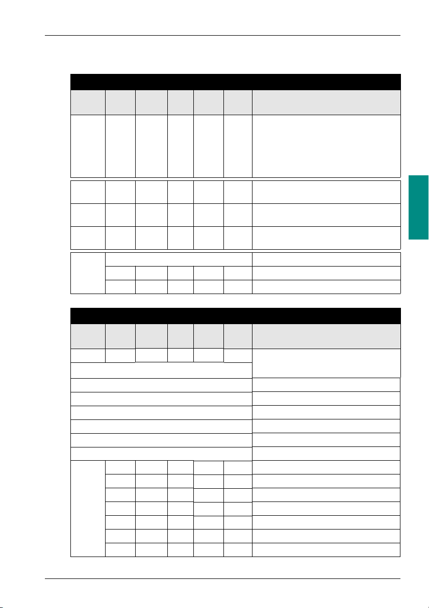
7 Connection capacities
Connectors
3 and 6 Pins - pitch: 3.81
Starter control and monitoring
Connection: 1 connector
- rigid conductor: .......................................
- flexible conductor:...................................
- conductor size: .......................................
- flexible conductor with terminal end:
- without insulated ferrule: ....................
- with insulated ferrule: .........................
Multiple connection:
(2 conductors with the same section)
- 2 rigid conductors: ..................................
- 2 flexible conductors:..............................
- 2 flexible conductors with terminal end:
- without insulated ferrule: ....................
- with insulated ferrule: .........................
Tightening torque: (0.2 / 0.25 N.m) 1.79 / 2.23 Lb-in
Flat-blade screwdriver: 2.5 mm (0.10 in)
0.14 to 1 mm
0.14 to 1 mm
AWG 28 to AWG 16
0.25 to 1. mm
0.25 to 0.5 mm
0.14 to 0.5 mm
0.14 to 0.75 mm
0.25 to 0.34 mm
0.75 mm
2
2
2
2
2
2
2
2
05-2003 21

DIA1ED3030204EN
05-2003
 Loading...