

1639093 03/2009
®
TeSys
UASILUFC5 - ASILUFC51
AS-i Communication Module
User Manual
03/2009
1639093
www.schneider-electric.com

Schneider Electric assumes no responsibility for any errors that may appear in this document. If you have
any suggestions for improvements or amendments or have found errors in this publication, please notify
us.
No part of this document may be reproduced in any form or by any means, electronic or mechanical,
including photocopying, without express written permission of Schneider Electric.
All pertinent state, regional, and local safety regulations must be observed when installing and using this
product. For reasons of safety and to help ensure compliance with documented system data, only the
manufacturer should perform repairs to components.
When devices are used for applications with technical safety requirements, the relevant instructions must
be followed.
Failure to use Schneider Electric software or approved software with our hardware products may result
in injury, harm, or improper operating results.
Failure to observe this information can result in injury or equipment damage.
© 2009 Schneider Electric. All rights reserved.
2 1639093 03/2009

Table of Contents
Safety Information . . . . . . . . . . . . . . . . . . . . . . . . . . . . . . . . . . . . . . . . . . . . 5
About the Book . . . . . . . . . . . . . . . . . . . . . . . . . . . . . . . . . . . . . . . . . . . . . . . 7
Chapter 1 Hardware Implementation . . . . . . . . . . . . . . . . . . . . . . . . . . . . . . . . . . . . . . 9
Description and Installation . . . . . . . . . . . . . . . . . . . . . . . . . . . . . . . . . . . . . . . . . . . . . . . . . . . . 10
Connections . . . . . . . . . . . . . . . . . . . . . . . . . . . . . . . . . . . . . . . . . . . . . . . . . . . . . . . . . . . . . . . 14
Technical Characteristics . . . . . . . . . . . . . . . . . . . . . . . . . . . . . . . . . . . . . . . . . . . . . . . . . . . . . 17
Chapter 2 Software Implementation . . . . . . . . . . . . . . . . . . . . . . . . . . . . . . . . . . . . . . . 19
Configuration Software . . . . . . . . . . . . . . . . . . . . . . . . . . . . . . . . . . . . . . . . . . . . . . . . . . . . . . . 20
Addressing . . . . . . . . . . . . . . . . . . . . . . . . . . . . . . . . . . . . . . . . . . . . . . . . . . . . . . . . . . . . . . . . 21
Description of the I/O Variables on the ASILUFC5/ASILUFC51 Module . . . . . . . . . . . . . . . . . 22
Managing Faults . . . . . . . . . . . . . . . . . . . . . . . . . . . . . . . . . . . . . . . . . . . . . . . . . . . . . . . . . . . . 23
1639093 03/2009 3

4 1639093 03/2009

§
Safety Information
Important Information
NOTICE
Read these instructions carefully, and look at the equipment to become familiar with the device before
trying to install, operate, or maintain it. The following special messages may appear throughout this
documentation or on the equipment to warn of potential hazards or to call attention to information that
clarifies or simplifies a procedure.
PLEASE NOTE
Electrical equipment should be installed, operated, serviced, and maintained only by qualified personnel.
No responsibility is assumed by Schneider Electric for any consequences arising out of the use of this
material.
A qualified person is one who has skills and knowledge related to the construction and operation of
electrical equipment and the installation, and has received safety training to recognize and avoid the
hazards involved.
1639093 03/2009 5

6 1639093 03/2009

At a Glance
Document Scope
Validity Note
Related Documents
About the Book
This manual describes the implementation, functionalities and operation of the TeSys U AS-i
communication module (ASILUFC5 or extended ASILUFC51).
Field of application: mainly automation systems in industry and building areas.
ASILUFC5 and ASILUFC51 can be used with TeSys U power bases (LUB/2B, LUS/2S) only.
ASILUFC5 and ASILUFC51 are not compatible with TeSys U controller bases (LUTM).
Title of Documentation Reference Number
ASILUF• Communication Module - Instruction Sheet 1743239
TeSys U Communication Variables - User’s Manual 1744082
LU•B/LU•S• TeSys U Starters - Instruction Sheet 1629984
LUCM/LUCMT Multifunction Control Units - User’s Manual 1743237
LUCM/LUCMT/LUCBT/LUCDT Control Units - Instruction Sheet AAV40504
LUCA/LUCB/LUCC/LUCD Control Units - Instruction Sheet AAV40503
User Comments
You can download these technical publications and other technical information from our website at
www.schneider-electric.com.
We welcome your comments about this document. You can reach us by e-mail at techcomm@schneiderelectric.com.
1639093 03/2009 7

8 1639093 03/2009

Hard
ware Implementation
1639093 03/2009
Hardware Implementation
Overview
This chapter describes the installation and technical characteristics of a TeSys U AS-i communication
module (ASILUFC5 or extended ASILUFC51).
What's in this Chapter?
This chapter contains the following topics:
Description and Installation 10
Connections 14
Technical Characteristics 17
1
Topic Page
1639093 03/2009 9

Hardware Implementation
Description and Installation
Introduction
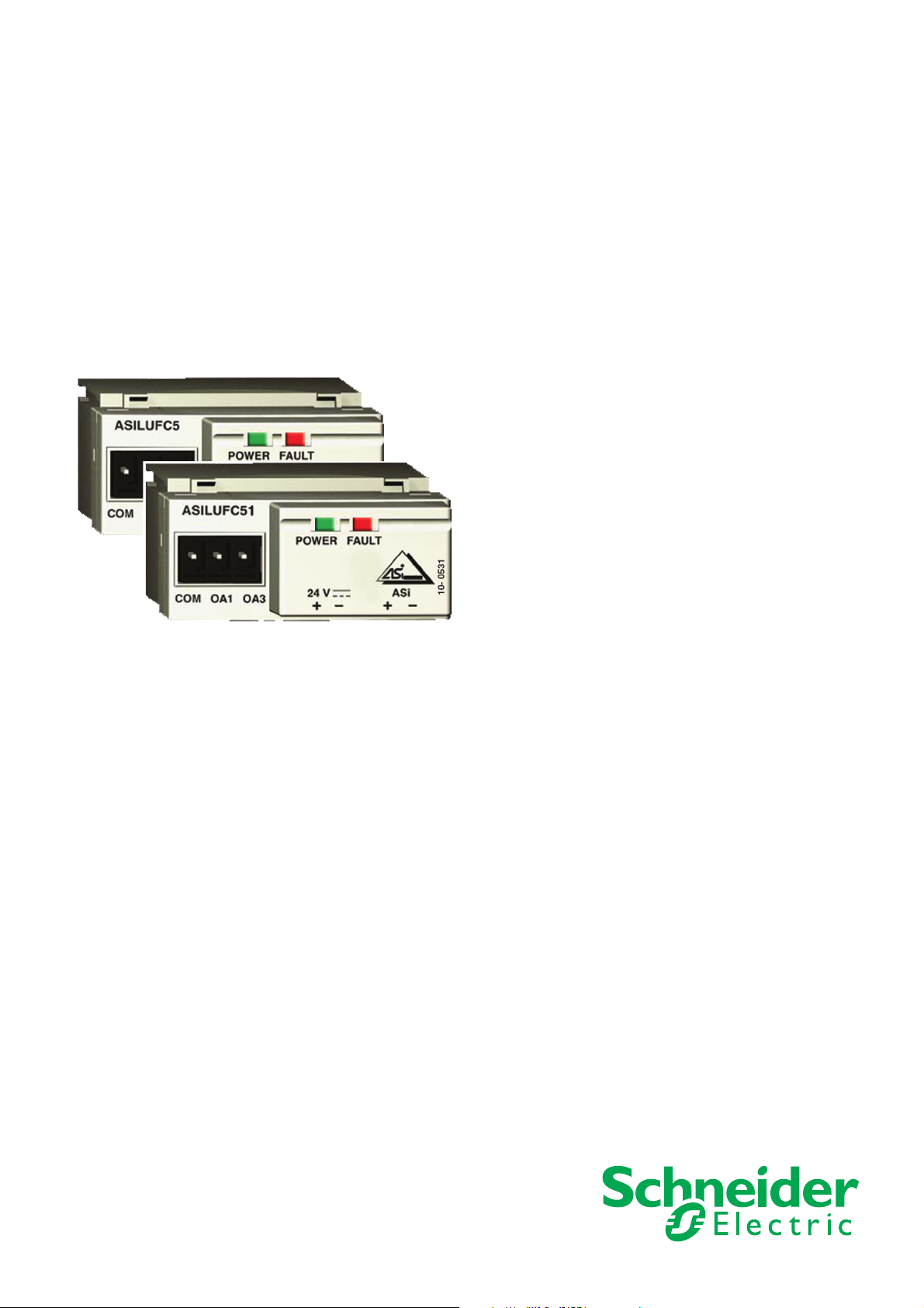
The AS-i ASILUFC5 or extended ASILUFC51 communication module connects the TeSys U starterscontrollers to the AS-i wiring system for direct or remote control.
The different operation conditions of the AS-i ASILUFC5 or ASILUFC51 AS-i communication module (ASi bus voltage presence, communication fault on AS-i bus, addressing fault, ...) are displayed on the front
panel by two light-emitting diodes (green and red).
Module operation is continuously monitored by self-tests. This is totally transparent to the user.
The integration of AS-i V2 functions enables remote module diagnostics via the bus or local diagnostics
via the ASITERV2 and XZMC11 addressing terminals.
The module must be supplied with a 24V DC auxiliary source and must only be used with the LUC••BL
24V DC control units.
IMPROPER COMMUNICATION PORT USAGE
Use communication ports for transfer of non-critical data only.
The data provided by monitoring contactor status and current levels is delayed by transmission time.
Do not use this data for critical control decisions.
Verify function settings before starting the motor.
Do not use functions such as Run, Stop and Reverse for emergency or critical control applications.
Failure to follow these instructions can result in death, serious injury, or equipment damage.
WARNING
10
1639093 03/2009

Description
Hardware Implementation
Description of ASILUFC5 or ASILUFC51 different states of LEDs.
Light Emitting Diodes (LEDs) Status Meaning
Green "Power" LED On AS-i bus voltage present
Off No AS-i bus voltage
Red "fault" LED On No exchange with the Master
(Communication fault on AS-i bus)
Addressing fault
(address is factory-set to 0)
Flashing No 24V DC auxiliary voltage
Motor feed engaged in the "TRIP" position
Off No fault
1639093 03/2009 11

Hardware Implementation
Installation
The AS-i ASILUFC5 or ASILUFC51 communication module is easily installed in the power base
(LUB••/LUS•• or LU2B••/LU2S••) under the LUC••BL control unit that locks it into position.
It must be assembled in the following order:
1. Install the ASILUFC5 or ASILUFC51 module.
2. Install the LUC••BL control unit.
Note: The control unit must be 24V DC.
3. The Output control connector can be connected by wire using LUBN11C cable (for LUB••/LUS••) or
LU9MR1C cable (for LU2B••/LU2S••).
Note: Direct wiring can be used, for example, to insert external stop control or a voltage interface.
12
1639093 03/2009

Once all components have been installed, here are complete power bases:
Hardware Implementation
1639093 03/2009 13

Hardware Implementation
Connections
Electrical Connections
The connections to the AS-i bus and auxiliary 24V DC are made using XZCG•• connecting accessories.
14
1639093 03/2009

Examples of Application Diagrams
Hardware Implementation
1639093 03/2009 15

Hardware Implementation
Connection Capacities
The following table shows the conductor cross-sections that may be used on ASILUFC5 / ASILUFC51
terminals:
Control / Monitor
Conductor Cross-section
(min. - max.)
0.14 ... 1 mm
[26 ... 18 AWG]
0.14 ... 1 mm
[26 ... 18 AWG]
0.25 ... 1.0 mm
[24 ... 18 AWG]
0.25 ... 0.5 mm
[24 ... 20 AWG]
0.14 ... 0.5 mm
[26 ... 20 AWG]
0.14 ... 0.75 mm
[26 ... 20 AWG]
0.25 ... 0.34 mm
[24 ... 22 AWG]
0.5 mm
2
[20 AWG]
Connection Conductor type
Rigid conductor
Flexible conductor
1 conductor
Flexible conductor with cable end:
without an insulating inlet taper
with an insulating inlet taper
2 rigid conductors
2 flexible conductors
2 conductors
(same
cross-section)
2 flexible conductors with cable end:
without an insulating inlet taper
with an insulating inlet taper
AS-i / 24V aux Conductor
Cross-section (min. - max.)
0.2 ... 1.5 mm
2
[24 ... 16 AWG]
0.2 ... 1.5 mm
2
[24 ... 16 AWG]
0.25 ... 1.5 mm
2
[24 ... 16 AWG]
0.25 ... 1.5 mm
2
[24 ... 16 AWG]
0.2 ... 1.0 mm
2
[24 ... 18 AWG]
0.2 ... 1.0 mm
2
[24 ... 18 AWG]
0.25 ... 1.0 mm
2
[24 ... 18 AWG]
0.5 ... 1.5 mm
2
[20 ... 16 AWG)
Connectors 2 pins 3 pins
Pitch 5.08 mm [0.20 in.] 3.81 mm [0.15 in.]
Tightening torque 4.4 to 5.3 lb-in
[0.5 / 0.6 N.m.]
4.4 to 5.3 lb-in
[0.5 / 0.6 N.m.]
Flat screwdriver 3.5 mm [0.14 in.] 2.5 mm [0.10 in.]
2
2
2
2
2
2
2
16
1639093 03/2009

Technical Characteristics
Technical Characteristics
Module certification ASI
Protection class Complying with IEC 539 IP20
Immunity to fast transients Complying with
AS-i power supply 26.5V - 31.6V
Current consumed On the AS-i bus 25mA in normal operation.
Auxiliary power supply 24V DC +/- 30%
Current consumed On the 24V auxiliary Depends on the load
Relay output rating Short-circuit and overload protected 0.5A / 24V
Hardware Implementation
2kV
IEC 1000-4-4 / EN 610004-4 level 4
30mA in fault.
connected to the outputs.
Limited to 500mA
1639093 03/2009 17

Hardware Implementation
18
1639093 03/2009

Sof
tware Implementation
1639093 03/2009
Software Implementation
Overview
Hardware implementation of an ASILUFC5 / ASILUFC51 AS-i communication module is being followed
by its software implementation.
What's in this Chapter?
This chapter contains the following topics:
Configuration Software 20
Addressing 21
Description of the I/O Variables on the ASILUFC5/ASILUFC51 Module 22
Managing Faults 23
2
Topic Page
1639093 03/2009 19

Software Implementation
Configuration Software
AS-i Comm. Module and PL7 Software
The AS-i communication module is configured with the PL7 Micro/Junior/Pro software.
All the slave equipment corresponding to all the inputs/outputs of the AS-i bus can be configured from the
PLC interface declaration screen.
Used with the Master PLC interface TSXSAY 1000 and to retain interchangeability compatibility with the
motor starters in box LF1/LF2.
The 7.D.F.0 motor start profile limits the configuration to 31 slave devices as a maximum. In fact, an
ASILUFC5 / ASILUFC51 module occupies the 2 addresses of banks A and B. The 7.A.7.E motor start
profile limits the configuration to 62 slave devices as a maximum.
The ASILUFC5 configuration is guided by the screen sequence. The following is a configuration example
with the Premium TSXSAY 1000 PLC interface.
Configuration Example (Steps 1-2)
Configuration example: step 1
20
Configuration example: step 2
1639093 03/2009

Addressing
Description of Addressing
Here is a view of the links with an addressing terminal, which can be of two differents types:
referenced as ASITERV2,
referenced as XZMC11.
Software Implementation
1639093 03/2009 21

Software Implementation
Description of the I/O Variables on the ASILUFC5/ASILUFC51 Module
AS-i Profiles
The following table describes the input and output variables associated to the AS-i profiles:
AS-i Profiles: 7.D.F.0 (for ASILUFC5) or 7.A.7.E (for ASILUFC51)
Current consumed on the AS-i bus 15mA typical
Bit value = 0 = 1
Data bits (commands)
(Outputs)
Data bits (status)
(Inputs)
If D0 and D1 output bits are set to 1 at the same time, the motor stops.
NOTE: The parameter bits are reserved.
D0 Stop direct direction Run forward direction
D1 Stop reverse direction Run reverse direction
D2 Reserved Reserved
D3 Reserved Reserved
D0 Not ready or in fault Ready
D1 Stopped Running
D2 Reserved Reserved
D3 Reserved Reserved
Schematic diagram
The ON, OFF, TRIP and power contact states are transmitted via a mechanical link.
22
1639093 03/2009

Managing Faults
Description of the Faults
Fault Causes Corrective actions
Green "Power"
LED Off
Red "Fault"
LED flashing
Red "Fault" LED
permanently On
Software Implementation
No AS-i bus voltage Check the state of the AS-i power supply
Check the cables and the connecting terminals
Check the polarity of the power supply wire
No 24V DC auxiliary voltage Check the state of the auxiliary power supply
Check the cables and connection terminals
Check the polarity of the power supply wire
Motor feed engaged in the
"TRIP" position
No exchange with the Master
(Communication fault on AS-i bus)
Addressing fault
(Address factory-set to 0)
Remove the cause of the fault
Rearm the product
Check the connection to the Master
Check if the Master is set to Run
Check if the 24V AS-i and 24V DC auxiliary connections are
not reversed
Set an address from 1 to 31 (ASILUFC5) or 1 to 62
(ASILUFC51)
1639093 03/2009 23

Software Implementation
24
1639093 03/2009
 Loading...