

Page 1
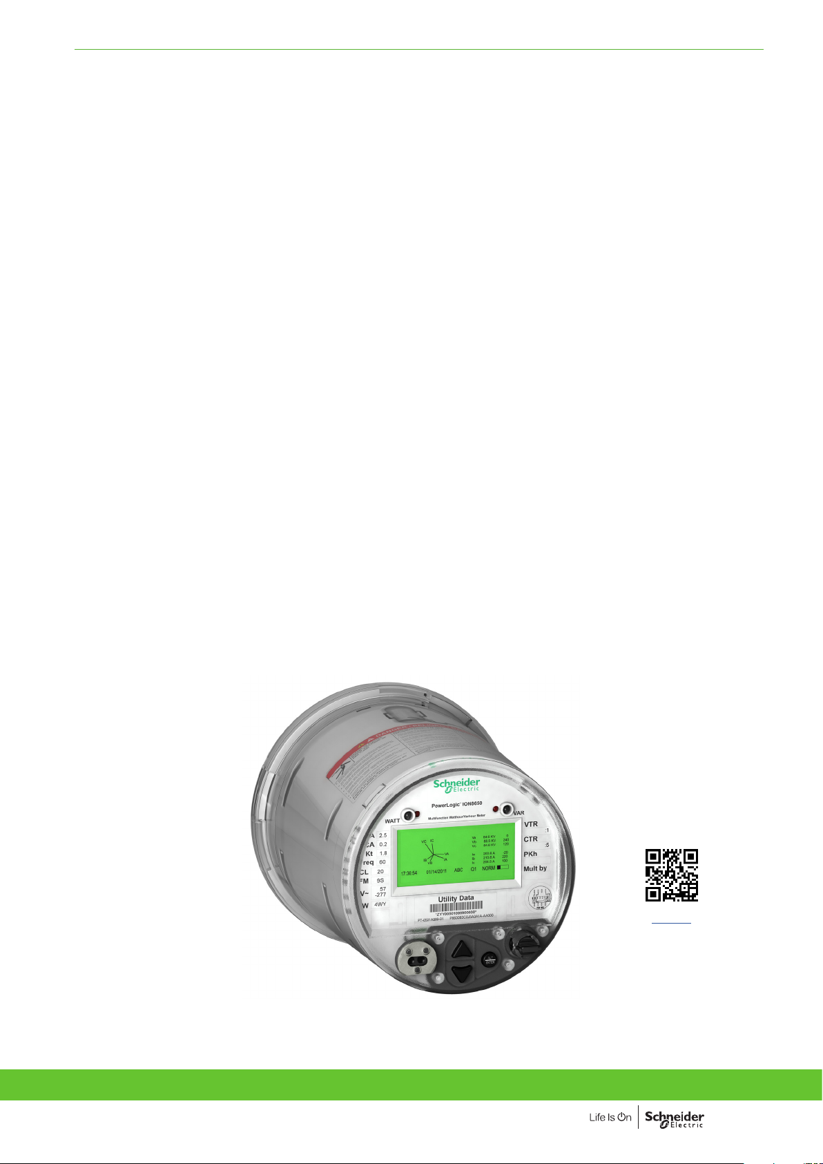
ADVANCED UTILITY METERING FUNCTIONS AND CHARACTERISTICS
ION8650 series
Technical Datasheet (US)
Providing high accuracy and a wide range of features for transmission and distribution metering,
the PowerLogic ION8650 advanced revenue and power quality meter has the flexibility to change
along with your needs. The meter provides the tools necessary to:
• Manage energy procurement and supply contracts
• Perform network capacity planning and stability analysis
• Monitor power quality compliance, supply agreements, and regulatory requirements
Applications
• Transmission and distribution metering
• Revenue metering
• Extensive power quality monitoring and analysis
• Power quality compliance monitoring
• Digital fault recording
• Instrument transformer correction
PB107500
Version: 1.0 - 22/03/2021
Version: 1.0 - 22/03/2021
PLSED310027EN_US
PLSED310027EN_US
ION8650
1
Page 2
ADVANCED UTILITY METERING FUNCTIONS AND CHARACTERISTICS
The solution for
Markets that can benefit from a solution that includes PowerLogic
ION8650 series meters:
• Transmission networks
• Distribution network
Benefits
• Reduce operations costs
• Improve power quality
• Improve continuity of service
Competitive advantages
• Be integrated into existing wholesale settlement system
• Be able to use Power Monitoring Expert software for data
analysis or share operation data with SCADA systems
through multiple communication channels and protocols
• Transformer/line loss compensation
• Instrument transformer correction
Power management solutions
Schneider Electric provides innovative
power management solutions to increase
your energy efficiency and cost savings,
maximise electrical network reliability and
availability, and optimise electrical asset
performance.
Conformity of standards
• IEC 62053-22/23
• IEC 61000-4-30
• EN 50160
• IEC 61000-4-7
• IEC 61000-4-15
• IEEE 1159
• IEEE 519
• IEC 61000-4-2
• IEC 61000-4-3
• IEC 61000-4-4
• IEC 61000-4-5
• IEC 61000-4-6
• IEC 61000-4-12
• CISPR 22
• IEC 62052-11
• IEC 60950
• ANSI C12.20
2
Version: 1.0 - 22/03/2021
PLSED310027EN_US
Page 3
ADVANCED UTILITY METERING FUNCTIONS AND CHARACTERISTICS
Main characteristics
Used to monitor electric energy provider networks, service entrances and
PB107500
substations, PowerLogic ION8650 meters are ideal for independent power
producers and cogeneration applications that need to accurately measure energy
bi-directionally in both generation and stand-by modes. These meters give utilities
the tools to manage complex energy supply contracts that include commitments to
power quality. Integrate them with our EcoStruxure™ Power Monitoring operations
software or other energy management and SCADA systems through multiple
communication channels and protocols, including Itron MV-90, Modbus, DNP,
DLMS, IEC 61850 Ed. 3.
Applications
• Revenue metering.
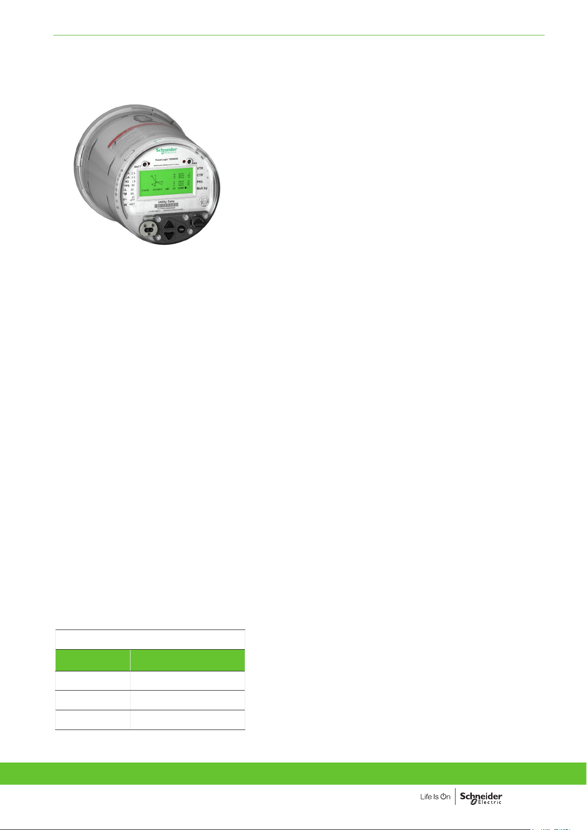
PowerLogic ION8650 socket meter
• Cogeneration and IPP monitoring.
• Compliance monitoring.
• Power quality analysis.
• Demand and power factor control.
• Load curtailment.
• Equipment monitoring and control.
• Energy pulsing and totalisation.
• Instrument transformer correction.
• Outage Notification
Feature selection
Commercial
reference number
S8650A
S8650B
S8650C
ION8650 meters
ION8650A
ION8650B
ION8650C
Main characteristics
• ANSI Class 0.1 and IEC 62053-22/23 Class 0.2 S metering
– For interconnection points on medium, high, and ultra-high voltage
networks; twice as accurate as current IEC and meets ANSI Class
standards over all conditions and including single wide range current
measurement.
• Power quality compliance monitoring
– Monitor compliance with international quality-of-supply standards (IEC
61000-4-30 Ed. 3 Class A/S, EN 50160 Ed. 4, IEC 61000-4-7, IEC 61000-415, IEEE 1159, IEEE 519). Also detects disturbance direction.
• Digital fault recording
– Simultaneous capture of voltage and current channels for sub-cycle
disturbance.
• Complete communications
– Multi-port, multi-protocol ports including serial, infrared, modem and
ethernet. Simultaneously supports multiple industry standard protocols
including: Itron MV-90, Modbus, Modbus Master, DLMS, DNP 3.0 and IEC
61850 Ed. 2.
• Multiple tariffs and time-of-use
– Apply tariffs, seasonal rate schedules to measure energy and demand
values for time periods with specific billing requirements.
• Multiple setpoints for alarm and functions
– Use up to 65 setpoints for single/multi-condition alarms and I/O functions
with response times down to 1/2 cycle.
• Multiple setpoints for alarm and functions
– Use up to 65 setpoints.
• Instrument transformer correction
– Save money and improve accuracy by correcting for less accurate
transformers.
• Alarm notification via email
– High-priority alarms, data logs sent directly to the user’s PC. Instant
notification of power quality events by email.
• Cyber security enhancements
– Assign communication admin rights to selected user; prevention measures
ensure no loss of security logs; support syslog for external security.
Version: 1.0 - 22/03/2021
Version: 1.0 - 22/03/2021
PLSED310027EN_US
PLSED310027EN_US
3
Page 4
ADVANCED UTILITY METERING FUNCTIONS AND CHARACTERISTICS
PE86302-95
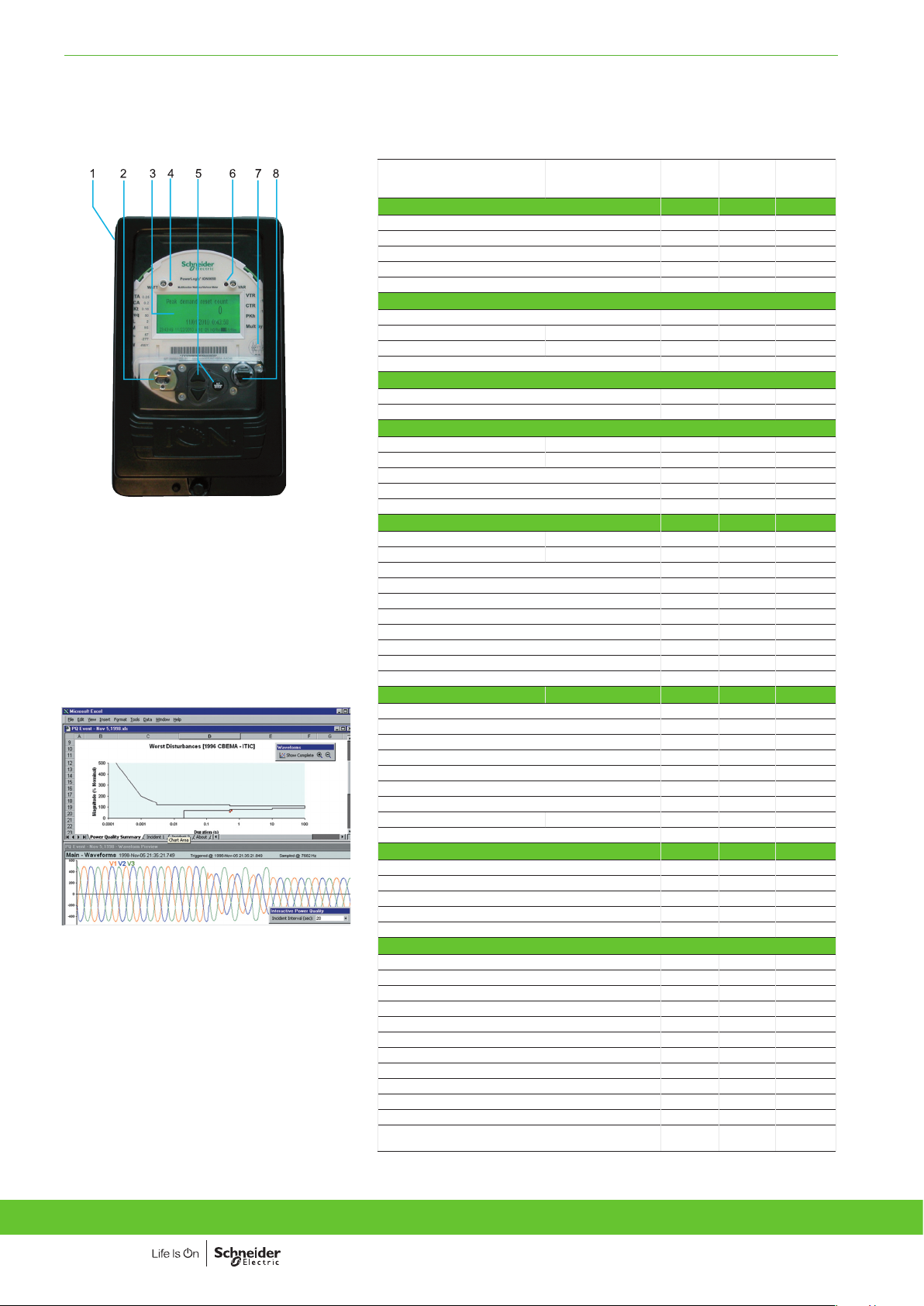
PowerLogic ION8650 switchboard meter.
1 Terminals
2 Optical port
3 Main display status bar
4 Watt LED
5 Navigation, ALT/Enter buttons
6 VAR LED
7 Nameplate label
8 Demand reset switch
PE86002
Disturbance waveform capture and power quality
report
Selection guide
ION8650 AION8650 BION8650
General
Use on LV, MV and HV systems
Current accuracy
Voltage accuracy
Power accuracy
Samples/cycle
b b b
0.1 % 0.1 % 0.1 %
0.1 % 0.1 % 0.1 %
0.1 % 0.1 % 0.1 %
1024 1024 1024
Instantaneous values
Current, voltage, frequency
Active, reactive, apparent power Total & per phase
Power factor Total & per phase
Current measurement range
b b b
b b b
b b b
0 A - 20 A 0 A - 20 A 0 A - 20 A
Energy values
Active, reactive, apparent energy
Settable accumulation modes
b b b
b b b
Demand values
Current
Active, reactive, apparent power
Predicted active, reactive, apparent power
Synchronisation of the measurement window
Demand modes: Block (sliding), thermal (exponential)
Present & max value s
Present & max values
b b b
b b b
b b b
b b b
b b b
Power quality measurements
Harmonic distortion Current & voltage
Individual harmonics Via front panel
Waveform / transient capture
Harmonics: magnitude, phase, and interharmonics
Detection of voltage sags and swells
IEC 61000-4-30 class A / S
IEC 61000-4-15 (Flicker)
High speed data recording (down to 10 ms)
EN 50160 compliance reporting
Programmable (logic and math functions)
b b b
63 63 31
b / b - / b - / -
50 40 -
b b b
A S
b b
b b
b b
b b b
Data recording
Onboard Memory (in Mbytes)
Revenue logs
Event logs
Historical logs
Harmonics logs
Sag/swell logs
Transient logs
Time stamping to 1 ms
GPS synchronisation (IRIG-B standard)
128 64 32
b b b
b b b
b b b
b b b
b b b
b
- -
b b b
b b b
Display and I/O
Front panel display
Wiring self-test (requires PowerLogic ION Setup)
Pulse output (front panel LED)
Digital or analogue inputsg (max)
Digital or analogue outputsg (max, including pulse output)
b b b
b b b
2 2 2
11 11 11
16 16 16
Communication
Infrared port
RS-485 / RS-232 port
RS-485 port
Ethernet port (Modbus/TCP/IP protocol) with gateway
Internal modem with gateway (ModemGate)
HTML web page server
IRIG-B port (unmodulated IRIG B00x time format)
Modbus TCP Master / Slave (Ethernet port)
Modbus RTU Master / Slave (Serial ports)
DNP 3.0 through serial, modem, and I/R ports
Cell modem option (LTE)
DLMS COSEM through serial, Ethernet and optical
ports for all variants
g
With optional I/O Expander.
gg
For 9S, and 36S only. For 35S system up to 480 V L-L.
ggg
C model limited to IR + 2 other ports at one time. Ports can be enabled/disabled by user.
1 1 1
1 1 1
1 1 1
1 1 1
1 1 1
b b b
1 1 1
b / b
b / b
b / b b / b
b b b
b b b
b b b
C
-
-
-
-
ggg
ggg
ggg
ggg
- / b
- / b
4
Version: 1.0 - 22/03/2021
PLSED310027EN_US
Page 5
ADVANCED UTILITY METERING FUNCTIONS AND CHARACTERISTICS
Electrical characteristics
PE86041
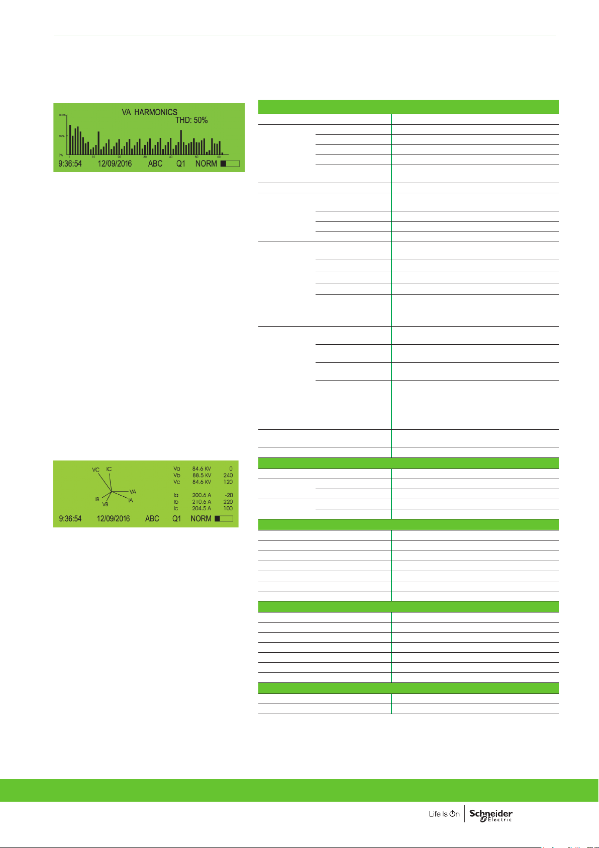
PowerLogic ION8650 front panel harmonic display.
PE86042
ION8650 front panel phasor display and table.
Type of measurement True rms 1024 samples per cycle
Current and voltage 0.1 % Reading
Power 0.1 %
Measurement
accuracy
Data update rate 0.5 cycle or 1 second (depending on value)
Input-voltage
characteristics
Input-current
characteristics
Power supply
Input/outputsggDigital outputs
Frequency ±0.001 Hz
Power factor 0.1 %
Energy
Nominal voltage
Maximum voltage 347 V L-N rms, 600 V L-L rms (9S)
g
Impedance
Inputs V1, V2, V3, VREF
Rated nominal/current
class
Accuracy range 0.01 - 20 A (standard range)
Measurement range 0.001 - 24 A
Permissible overload 500 A rms for 1 second, non-recurring
Burden per phase
Standard power
supply, blade powered
Auxiliary powered low
voltage
Auxiliary powered high
voltage
Ride-through time,
(Standard power
supply)
Digital inputs upto 3 Self-excited, dry contact sensing inputs
0.1 %, twice as accurate as ANSI Class 0.2 and
IEC 62053-22/23 (0,2S)
57 V to 277 V L-N rms
100 V to 480 V L-L rms (35S)
5 MW /phase (phase-Vref/Ground)
1A, 2 A, 5 A and/or 10 A (Class 1/2/10/20)
Socket: Typical: 3 W, 8 VA/phase, 3-phase
operation; Maximum: 4 W, 11 VA/phase, 3-phase
operation
Switchboard: 0.05 V A at 1 A (0.05 Ω max)
120-277 V L-N RMS (-15 %/+20 %) 47-63 Hz or
120-480 V L-L RMS (-15 %/+20 %) 47-63 Hz (35S)
AC: 65-120 (+/- 15 %) VLN RMS, 47-63 Hz
DC: 80-160 (+/- 20 %) VDC
AC: 160-277 (+/- 20 %) V L-N RMS, 47-63 Hz
DC: 200-300 (+/- 20 %) V DC
Socket: min guaranteed: 6 cycles at nominal
frequency (minimun 50 Hz), at 120 V L-N rms (208
V L-L rms) 3-phase operation
Switchboard: min guaranteed: 6 cycles at nominal
frequency (minimun 50 Hz), at 120 V L-N rms (208
V L-L rms) 3-phase operation
4 (Form C) Solid state relays (130 V AC/ 200 V DC)
50 mA AC/DC, 1 (Form A) output
Mechanical characteristics
Weight 7.0 kg
IP degree of
protection
Dimensions Socket 178 x 237 mm
Socket Front IP65, back IP51
Switchboard Front IP50, back IP30
Switchboard 285 x 228 x 163 mm
Environmental conditions
Operating temperature -40 °C to 85 °C
Display operating range -40 °C to 70 °C
Storage temperature -40 °C to 85 °C
Humidity rating 5 % to 95 % RH non-condensing
Pollution degree 2
Installation category Cat III
Dielectric withstand 2.5 kV
Electromagnetic compatibility
Electrostatic discharge IEC 61000-4-2
Immunity to radiated fields IEC 61000-4-3
Immunity to fast transients IEC 61000-4-4
Immunity to surge IEC 61000-4-5
Immunity conducted IEC 61000-4-6
Damped oscillatory waves immunity IEC 61000-4-12
Conducted and radiated emissions CISPR 22 (class B)
Safety
Europe As per IEC 62052-11
North America As per ANSI C12.1
g
Specications are limited by the operating range of the power supply if a non-aux power supply is used.
gg
More input and output selections available via optional I/O expander.
Version: 1.0 - 22/03/2021
Version: 1.0 - 22/03/2021
PLSED310027EN_US
PLSED310027EN_US
5
Page 6
ADVANCED UTILITY METERING FUNCTIONS AND CHARACTERISTICS
Communication
PB117744
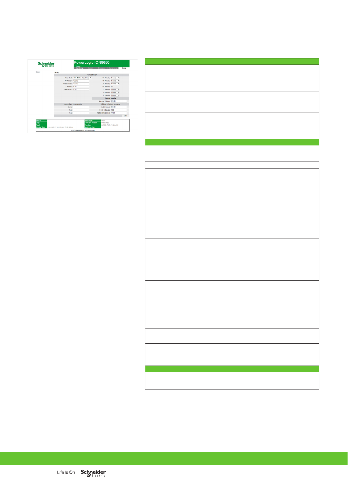
Example embedded webserver page (WebMeter) showing
realtime values.
RS-232 / RS-485 port (COM1) User-selectable RS-232 or RS-485.
Internal modem port (COM2) 300-57,600 bps
ANSI 12.18 Type II optical
port (COM3)
RS-485 port (COM4) Up to 57,600 baud, Modbus, direct connection to a PC
Ethernet port 10/100BASE-T, RJ45 connector, protocols:
EtherGate Up to 31 slave devices via serial ports
ModemGate Up to 31 slave devices
Firmware characteristics
High-speed data recording Up to 1/2-cycle interval burst recording, stores detailed
Harmonic distortion Up to 63rd harmonic for all voltage and current inputs
Dip/swell detection Analyse severity/potential impact of sags and swells:
Instantaneous High accuracy measurements with 1s or 1/2 cycle update
Load profiling Channel assignments are user configurable:
Waveform captures Simultaneous capture of all voltage and current channels
Alarms Threshold alarms:
Advanced security Up to 50 users with unique access rights. Perform resets,
Transformer correction Correct for phase / magnitude inaccuracies in current
Memory 128 MB (A), 64 MB (B), 32 MB (C)
Firmware update Update via the communication ports
Display characteristics
Type FSTN transreflective LCD
Backlight LED
Languages English
300 - 115,200 baud (RS-485 limited to 57,600 bps);
protocols: ION, Modbus/RTU/Mastering, DLMS, DNP 3.0,
GPSTRUETIME/DATUM.
Up to 57,600 bps
or modem
DNP, ION, Modbus/TCP/Mastering, IEC 61850 Ed. 2
or 100BASE-FX multimode, male ST connectors, DLMS
characteristics of disturbances or outages. Trigger recording
by a user-defined setpoint, or from external equipment.
– magnitude and duration data suitable for plotting on
voltage tolerance curves
– per phase triggers for waveform recording or
control operations
rate for:
– voltage and current
– active power (kW) and reactive power (kVAR)
– apparent power (kVA)
– power factor and frequency
– voltage and current unbalance
– phase reversal
– 800 channels via 50 data recorders (feature set A),
– 720 channels via 45 data recorders (feature set B),
– 80 channels via 5 data recorders (feature set C).
Configure for historical trend recording of energy, demand,
voltage, current, power quality, other measured parameters.
Recorders can trigger on time interval basis, calendar
schedule, alarm/event condition, manually.
– sub-cycle disturbance capture (16 to 1024
samples/cycle)
– adjustable pickup and dropout setpoints and time
delays, numerous activation levels possible for a
given type of alar m
– user-defined priority levels
– boolean combination of alarms
time syncs, or meter configurations based on user
privileges.
transformers (CTs), potential transformers (PTs)
6
Version: 1.0 - 22/03/2021
PLSED310027EN_US
Page 7
ADVANCED UTILITY METERING FUNCTIONS AND CHARACTERISTICS
Commercial reference numbers
Item Code Description
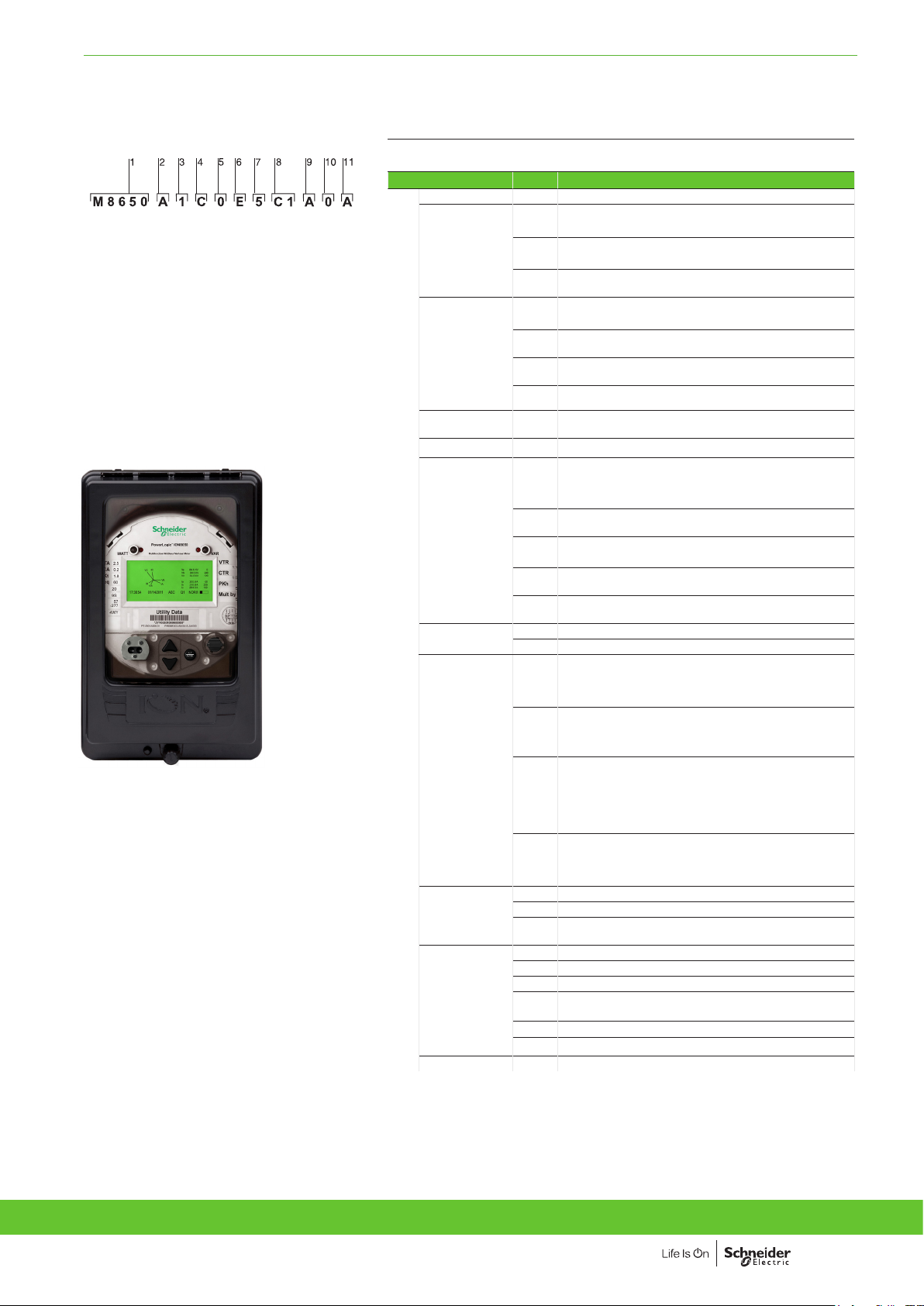
PE86043-C
Example product part number.
1 Model.
2 Feature set.
3 Form factor.
4 Current Inputs.
5 Voltage inputs.
6 Power supply.
7 System frequency.
8 Communications.
9 Input/output options.
10 Security.
11 Special order options.
PB107507
PowerLogic ION8650 meter with switchboard
case
1 Model M8650 Schneider Electric energy and power quality meter.
2 Feature Set A 128 MB Memory Class A power quality analysis, waveforms
3 Form Factor (1) 0 Form 9S/29S/36S Base, 57-277 V L-N (autoranging)
4 Current Inputs C 1, 2 or 5 A nominal, 20 A full scale (24 A fault capture,
5 Voltage Inputs 0 Standard (see Form Factor above)
6 Power SupplygE Form 9/29/35/36S, (socket) and Form 9, 36 (FT21
7 System
Frequency
8 Communications C 7 Infrared optical port, Ether net (10/100BASE-T), RS-
9 Onboard I/O A None.
10 Security 0 Password protected no security lock.
11 Special Order A None
g
Specications are limited by the operating range of the power supply if a non-aux power supply is used.
and transient capture with 1024 sampl es/cycle.
B 64 MB memory, energy meter Class S EN 50160 Ed. 4
power quality monitoring.
C 32 MB memory, basic tariff/energy metering (5 data
recorders, 80 channels).
3-Element, 4-Wire / 2 1/2-Element, 4-Wire
1 Form 35S Base - 120-480 V L-L (autoranging) 2-Element,
3-Wire
4 Form 9/29/35/36S FT21 Switchboard (meter + case) with
break out panel
7 Form 9/29/35/36S FT21 Switchboard (meter + case) with
break out cable
start at 0.001 A)
switchboard): 120-277 V AC. Form 35S (socket) and Form
35 (FT21 switchboard): 120-480 V AC. Powered from the
meter’s voltage connections.
H Auxiliary Power Pigtail: 65-120 V AC or 80-160 V DC
(power from external source)
J Auxiliary Power Pigtail: 160-277 V AC or 200-300 V DC
(power from external source)
K Auxiliary Power Pigtail: 65-120 V AC, 80-160 V DC (power
from external source), Universal Socket Style
L Auxiliary Power Pigtail: 160-277 V AC, 200-350 V DC
(power from external source), Universal Socket Style
5 Calibrated for 50 Hz systems.
6 Calibrated for 60 Hz systems.
232/485 port, RS-485 port (note: in addition to infrared
optical port, Feature Set C can use any two ports
(configurable)), 56 k universal internal modem (RJ11)
E 1 Infrared optical port, Ethernet (10/100BASE-T), RS
232/485 port, RS-485 port (note: in addition to infrared
optical port, Feature Set C can use any two ports
(configurable))
F 1 Infrared Optical port, Ethernet (100BASE-FX multi-mode)
with male ST connectors (available on socket meters only,
Forms 0 & 1 above. I/O card not available if this option is
ordered.) RS-232/485 port, RS-485 port (Note: in addition
to Infrared Optical port Feature Set C can use any two
ports (configurable))
S 1 Infrared optical port, Ethernet (10 BASE-T), RS-232/485
port, RS-485 port (note: in addition to infrared optical
port, Feature Set C can use any two ports (configurable)),
Verizon 4G LTE cell modem.
B 4 Form C digital outputs, 3 Form A digital inputs.
C 4 Form C digital outputs, 1 Form A digital output, 1 digital
input.
1 Password protected with security lock enabled
3 RMICAN (Measurement Canada approved)
4 RMICAN-SEAL (Measurement Canada approved, and
factory sealed)
7 Password protected, no security lock (US only)
8 Password protected with security lock enabled (US only)
Version: 1.0 - 22/03/2021
Version: 1.0 - 22/03/2021
PLSED310027EN_US
PLSED310027EN_US
7
Page 8
ADVANCED UTILITY METERING FUNCTIONS AND CHARACTERISTICS
Commercial reference numbers (cont.)
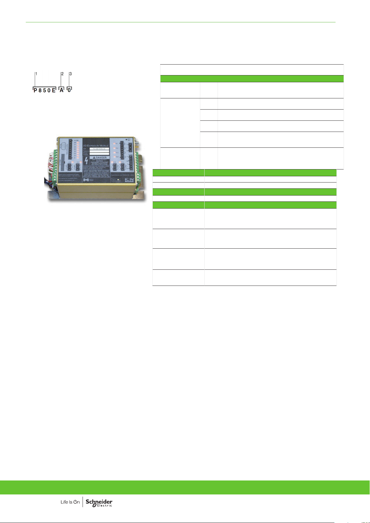
I/O Expander
PE86044_1
Example order code. Use this group of codes when ordering
the I/O Expander.
1 Digital / Analogue I/O.
2 I/O option.
3 Cable option.
PE86131
Digital/Analogue
I/O
I/O option A External I/O box with 8 digital inputs and 8 digital outputs
Cable 0 No cable - cables for the I/O box are no ordered as a separate
Comm. ref. no. A-base adapters
A-BASE-ADAPTER-9
A-BASE-ADAPTER-35
OPTICAL-PROBE
CBL-8X00BRKOUT
CBL-8X00IOE5FT
CBL-8X00IOE15FT
CBL-8XX0-BOP-IOBOX
P850E Schneider Electric I/O Expander for ION8600 meters: Inputs
and Outputs for energy pulsing, control, energy counting,
status monitoring, and analogue interface to SCADA.
(4 Form A, 4 Form C)
B External I/O box with 8 digital inputs and 4 digital outputs
(4 Form C) and 4 analogue outputs (0 to 20 mA)
C External I/O box with 8 digital inputs and 4 digital outputs
(4 Form C) and 4 analogue outputs (-1 mA to 1 mA)
D External I/O box with 8 digital inputs and 4 digital outputs
(4 Form C) and 4 analogue outputs (two -1 to 1 mA, and two 0
to 20 mA outputs)
part number. Refer to commercial reference numbers: CBL8X00IOE5FT, CBL-8X00IOE15FT and CBL-8XX0-BOP-IOBOX
under Connector cables, below.
Form 9S to Form 9A adapter
Form 35S to Form 35A adapter
Optical communication interface
Optical communication interface
Connector cables
1.5 m extension cable, mates with 24-pin male Molex connector
from the meter to the 24-pin Molex connector on the I/O
expander box (not for use with breakout panel E8, F8 & G8 form
factors)
44.57 m extension cable, mates with 24-pin male Molex
connector from the meter to the 24-pin Molex connector on the
I/O expander box (not for use with breakout panel E8, F8 & G8
form factors)
44.57 m extension cable, mates with 24-pin male Molex
connector from the meter to the 24-pin female Molex connector
on the I/O Expander box (not for use with breakout panel E8, F8
& G8 form factors)
1.8 m connector cable, 24-pin male to 14-pin male Molex
connector for connecting an ION8000 Series meter with breakout
panel to an I/O Expander Box
8
Version: 1.0 - 22/03/2021
PLSED310027EN_US
Page 9
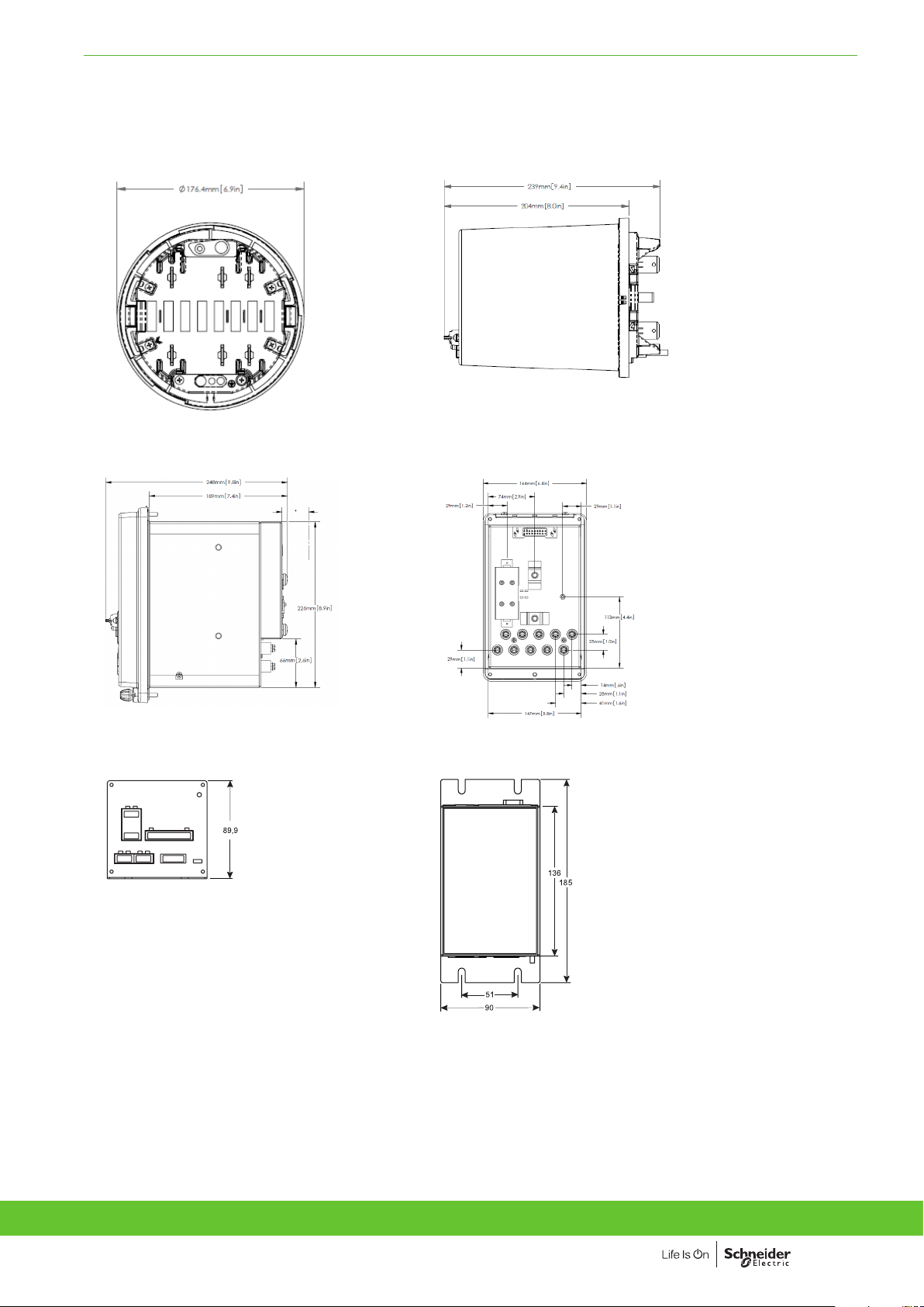
ADVANCED UTILITY METERING DIMENSIONS AND CONNECTION
ION8650 socket dimensions
PE86303PE86305PE86350
ION8650 switchboard dimensions
PE86304PE86306PE86351
I/O Expander dimensions
Version: 1.0 - 22/03/2021
PLSED310027EN_US
9
Page 10
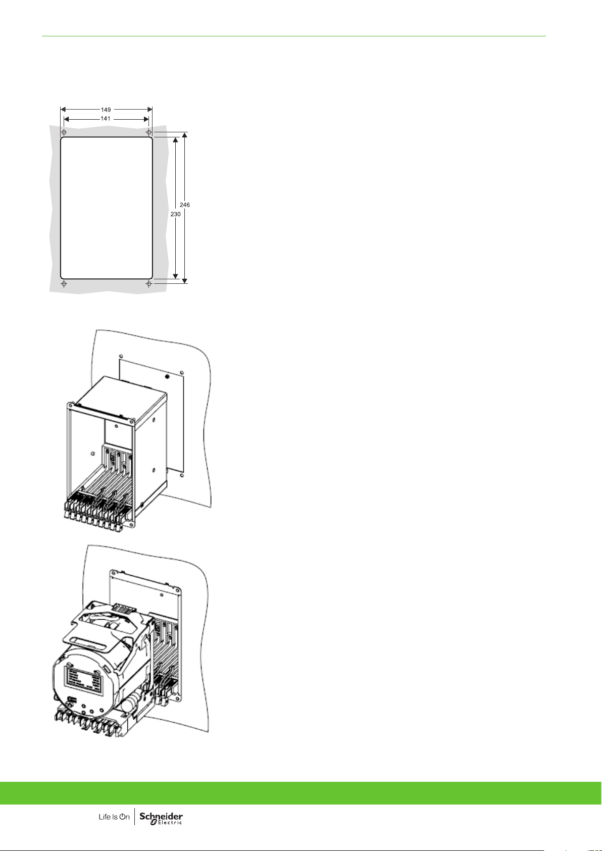
ADVANCED UTILITY METERING FUNCTIONS AND CHARACTERISTICS
ION8650 suggested switchboard mounting dimensions
PE86052
ION8650 switchboard mounting
PE86309
PE86310
Please see appropriate Installation Guide for these products for further details.
10
Version: 1.0 - 22/03/2021
PLSED310027EN_US
Page 11

Schneider Electric Industries SAS
35, Rue Joseph Monier,
CS 30323
F - 92506 Rueil Malmaison Cedex
RCS Nanterre 954 503 439
Capital social 896 313 776
www.se.com
March 2021
ION8650 Series US Version
PLSED310027EN_US
As standards, specications and designs develop from time to time, please ask
for conrmation of the information given in this document.
Design: Schneider Electric
Photos: Schneider Electric
Over 75 % of Schneider Electric products
have been awarded the Green Premium ecolabel.
© 2021 – Schneider Electric - All rights reserved
 Loading...