

Page 1

Watson Ethernet
Operating Manual
Document Identification
Watson-Ethernet-Manual.doc
Document Version
3.3-01
Document Revision
2010-01-20
Distribution
Customer
Page 2

Watson Ethernet
Operating Manual
Watson-Ethernet-Manual.doc
Version 3.3-01
ii
Revision: 2010-01-20
Revision History
Revision
Date
Author
Remarks
3.3-01
100120
MLr
Update for tabletop FW 5.1
3.2-01
091119
MLr
Update for plug-in FW 3.1
3.1-01
090226
MLr
Replaced SZ.846 with SZ.847 tabletops
3.0-01
080208
RBt
Update for plug-in FW 3.0
2.2-02
070814
RBt
Clarifications on DEFAULT and BITRATE commands
2.2-01
070727
RBt
Update for plug-in FW 2.4
2.1-01
070228
RBt
Update for plug-in FW 2.3
2.0-01
060427
RBt
Update for plug-in FW 2.0/2.1/2.2
1.1-01
060225
RBt
Update for plug-in FW 1.1 and tabletop FW 2.2
1.0-01
051130
RBt
First version
Copyright 2010 by Schmid Telecommunication, Zurich, Switzerland. All rights reserved. Reproduction of part or all of
the contents in any form is expressly prohibited without the prior written consent of Schmid Telecommunication.
Schmid Telecommunication has used its discretion, best judgments and efforts in preparing this document. Any information contained in this document is provided without any warranty of any kind. Schmid Telecommunication hereby disclaims any liability to any person for any kind of damage. Schmid Telecommunication may make improvements and/or changes of this document at any time.
Page 3

Revision: 2010-01-20
Declaration of Conformity
Tabletop
Watson Ethernet tabletop 1p Ethernet
SZ.847.V350
Watson Ethernet tabletop 2p 1xEth
SZ.847.V450
Plug-in
Watson Ethernet plug-in, 4 x Ethernet, 4 x DSL
SZ.866.V654
Manufacturer:
Schmid Telecom AG, Binzstrasse 35, CH-8045 Zurich
The products mentioned above comply with the regulations of the following European Directives:
2004/108/EC
Directive containing requirements regarding
electromagnetic compatibility.
The compliance of the above mentioned product with the requirements of the directive 2004/108/EC is ensured by complete application of the following harmonized European Standards:
EN 300386:2000
2006/95/EC
Directive containing requirements regarding
safety.
The compliance of the above mentioned product with the requirements of the directive 2006/95/EC is ensured by complete application of the following harmonized European Standards:
EN 60950:2006 (IEC 60950:2005)
99/5/EEC
Directive containing requirements regarding
Radio & Telecommunication Terminal
Equipment.
The compliance of the above mentioned product with the requirements of the directive 99/5/EEC is ensured by complete
application of the following harmonized European Standards:
EN 55022:1998, EN 55024:1998
EN 60950:2006 (IEC 60950:2005)
2002/96/CE
Directive containing requirements regarding
the prevention of waste electrical and electronic equipment (WEEE), and in addition,
the reuse, recycling and other forms of recovery of such wastes so as to reduce the
disposal of waste.
The product mentioned above is labeled in accordance with
European Directive 2002/96/EC concerning waste electrical
and electronic equipment (WEEE). The Directive determines
the framework for the return and recycling of used appliances
as applicable throughout the European Union. This label is
applied to the product to indicate that the product is not to be
thrown away, but rather reclaimed upon end of life per this
Directive.
Page 4

Watson Ethernet
Operating Manual
Watson-Ethernet-Manual.doc
Version 3.3-01
iv
Revision: 2010-01-20
2002/95/CE
Directive containing requirements to approximate the laws of the Member States on the
restrictions of the use of hazardous substances (RoHS) in electrical and electronic
equipment and to contribute to the protection
of human health and the environmentally
sound recovery and disposal of waste electrical and electronic equipment.
The product mentioned above has been designed and produced following the Directive 2002/95/EC of the European
Parliament and of the Council of 27 January 2003 on the restriction of the use of certain hazardous substances in electrical and electronic equipment and is compliant to the allowed concentration values defined by the European Committee.
The compliance of the above mentioned products with the specified requirements of the applicable directives
and harmonized and non-harmonized standards is shown in the following internal and external test reports:
W5A Safety Report.pdf
W5B LTU 4xEth 4xDSL Protection Report 0.1.doc
Watson_ETH_EMC_Report_1.0.pdf
Watson_Ethernet_MS_EMC_External_Report_1_EMCKP1240A.pdf
SZ.847.Vxxx Safety Report EN60950.pdf (tabletop, external)
CE Label attached to the product(s):
on tabletop, for plug-in on minirack and on 19” subrack
Issued by:
Schmid Telecom AG
Binzstrasse 35
CH-8045 Zurich
Place and date:
Zurich, 2009-02-26
Signatures:
Signature 1
Ronny Colotto
Signature 2
Marcel Beerli
Page 5

Revision: 2010-01-20
Important Safety Precautions
To reduce the risk of fire, bodily injury, and damage to the equipment the following precautions must be observed:
Read and follow all warning notices and instructions marked on the product
or included in the manual.
Installation of this equipment has to be done by qualified personnel only.
To achieve safety and satisfactory EMC performance, the plug-in boards
have to be inserted into appropriate subracks. Subrack slots that are not
used must covered with a blanking plate.
The subracks must be connected to earth. This is achieved by installing the
subracks into properly grounded rack or by connecting the protective ground
terminal provided on some subracks to the earthing network.
If the subracks are installed in racks then these racks must be connected to
the earthing network according to ETS 300 253.
Where protective ground terminals are available on the subracks these ter-
minals are marked with the symbol . The following rules must be observed:
The earthing network must be connected to the protective ground termin-
al continuously and securely.
Where the subracks are fitted with an AC power connector the earthing
network must be connected securely to the protective ground terminal
even if the AC power cord is disconnected from the subracks.
The protective grounding may only be disconnected from the subracks af-
ter the DSL line has been disconnected from the plug-in.
Ground terminals on the tabletop modems are marked with the symbol .
The following rules must be observed:
Use of the ground terminal is optional. If used then the earthing network
must be connected to the ground terminal continuously and securely.
Otherwise the ground terminal can be left open.
The grounding may only be disconnected from the modem after the DSL
line has been disconnected.
This product is to be used with telecommunications circuits. Take the follow-
ing precautions:
Never install telephone wiring during a lightning storm.
Never install telephone jacks in wet locations unless the jack is specifical-
ly designed for wet locations.
Never touch uninsulated telephone wires or terminals unless the tele-
phone line has been disconnected at the network interface.
Use caution when installing or modifying telephone lines.
Page 6

Watson Ethernet
Operating Manual
Watson-Ethernet-Manual.doc
Version 3.3-01
vi
Revision: 2010-01-20
Avoid using a telephone (other than a cordless type) during an electrical
storm. There may be a remote risk of electric shock from lightning.
Do not use the telephone to report a gas leak in the vicinity of the leak.
Condensation may occur externally or internally if this product is moved from
a colder room to a warmer room. When moving this product under such conditions, allow ample time for this product to reach room temperature and to
dry before operating.
This product is intended for use in environments as stated in the technical
specifications. Do not use this product in areas classified as hazardous locations. Such areas include patient care areas of medical and dental facilities,
oxygen-laden environments, or industrial facilities. Contact your local electrical authority governing building construction, maintenance, or safety for
more information regarding the installation of this product.
Slots and openings in this product are provided for ventilation and should
never be blocked or covered, since these ensure reliable operation of this
product and protect it from overheating. This product should not be placed in
a built-in apparatus such as a rack unless the apparatus has been specifically
designed to accommodate the product, proper ventilation is provided for the
product, and the product instructions have been followed.
This product should be placed away from radiators, heat registers, stoves, or
other pieces of equipment that produce heat. Allow sufficient air circulation
around the product and the AC adapter during use to ensure adequate cooling of the device.
Do not use this product in a wet location.
Normal operation of this product is only possible when the external housing is
left in place.
This product should be operated only from the type of power source indicated
on the product's electrical ratings label. If you have questions about the type
of power source to use, contact your local Schmid Distributor or local power
company.
Be sure that the power outlet you plug the power cord into is easily accessi-
ble and located as close to the equipment operator as possible. When you
need to disconnect power to this product, be sure to unplug the power cord
from the electrical outlet.
Ensure that the voltage select switch, if provided on this product, is in the cor-
rect position for the type of voltage in your country (115 VAC or 230 VAC).
Do not allow anything to rest on any of the attached cables and do not posi-
tion this product where persons will walk or trip on the cables.
Unplug this product from the wall outlet before cleaning. Do not use liquid
cleaners or aerosol cleaners. Use a damp cloth for cleaning.
Never push a foreign object through an opening in this product.
Page 7

Watson-Ethernet-Manual.doc
Version 3.3-01
Watson Ethernet
Operating Manual
Revision: 2010-01-20
vii
Unplug the product from the electrical outlet and contact your local Schmid
Distributor under the following conditions:
The power cord, extension cord, or plug is damaged.
Liquid has been spilled or an object has fallen into this product.
This product has been exposed to water.
This product has been dropped or damaged in any way.
There are noticeable signs of overheating.
This product does not operate normally when you follow the operating in-
structions.
Do not attempt to service this product yourself, as opening or removing cov-
ers may expose you to dangerous high voltage points or other risks. Refer all
servicing to your local Schmid Distributor.
Upon completion of any service or repairs to this product, have your local
Schmid Distributor perform any safety checks required by the repair procedure or by local codes to determine that the product is in proper operating
condition.
Page 8

Page 9

Revision: 2010-01-20
ix
Limited Product Warranty
Schmid Telecom warrants that for two (2) years from the date of shipment to the
Customer, all products manufactured by Schmid Telecom will be free from defects in materials and workmanship. Schmid Telecom also warrants that products
will conform to the applicable specification and drawings for such products, as
contained in the Product Manual on in Schmid Telecom internal specifications
and drawings for such products (which may or may not be reflected in the Product Manual). This warranty only applies if Customer gives Schmid Telecom written notice of defects during the warranty period. Upon such notice, Schmid Telecom will, at its option, either repair or replace the defective item.
If Schmid Telecom is unable, in a reasonable time, to repair or replace any
equipment to a condition as warranted, Customers is entitled to a full refund of
the purchase price upon return of the equipment to Schmid Telecom. This warranty applies only to the original purchaser and is not transferable without Schmid Telecom express written permission. This warranty becomes null and void if
Customer modifies or alters the equipment in any way, other than as specifically
authorized by Schmid Telecom.
Except for the limited warranty described above, the foregoing constitutes the
sole and exclusive remedy of the Customer and the exclusive liability of Schmid
Telecom and is in Lieu of any and all other warranties (expressed or implied).
Schmid Telecom specifically disclaims all other warranties, including (without limitation), all warranties of merchantability and fitness for a particular purpose.
Some states do not allow the exclusion of implied warranties, so this exclusion
may not apply to Customer.
In no event will Schmid Telecom or its suppliers be liable to Customer for any incidental, special, punitive, exemplary or consequential damages experienced by
either Customer or a third party (including, but not limited to, loss of data or information, loss of profits, or loss of use). Schmid Telecom is not liable for damages for any cause whatsoever (whether based in contract, tort, or otherwise) in
excess of the amount paid for the item. Some states do not allow the limitation or
exclusion of liability for incidental or consequential damages, so the above limitation or exclusion may not apply to Customer.
Page 10

Page 11

Revision: 2010-01-20
xi
Table of Contents
1 Related Documents ......................................................................................................................... 1-1
2 Overview ........................................................................................................................................... 2-1
2.1 Introduction .............................................................................................................................. 2-1
2.2 Applications ............................................................................................................................. 2-1
3 Modem Features .............................................................................................................................. 3-1
3.1 DSL .......................................................................................................................................... 3-1
3.1.1 Linerates and DSL sync rates ...................................................................................... 3-1
3.1.2 Multipair operation ....................................................................................................... 3-2
3.1.3 Single-pair fallback ....................................................................................................... 3-3
3.1.4 Power Backoff .............................................................................................................. 3-4
3.1.5 Symmetric and Asymmetric PSDs ............................................................................... 3-4
3.1.6 DSL Performance Parameters..................................................................................... 3-4
3.1.7 Wetting Current ............................................................................................................ 3-6
3.1.8 Master / Slave .............................................................................................................. 3-7
3.1.9 DSL Clocking ............................................................................................................... 3-7
3.2 Ethernet (plug-in modem) ........................................................................................................ 3-7
3.2.1 Ethernet over DSL ....................................................................................................... 3-7
3.2.2 Ethernet Bridging ......................................................................................................... 3-8
3.2.3 MAC Defect Signaling .................................................................................................. 3-9
3.2.4 VLANs .......................................................................................................................... 3-9
3.2.5 VLAN Examples ........................................................................................................... 3-9
3.2.6 Individual and shared forwarding databases ............................................................. 3-11
3.2.7 Stacked VLANs .......................................................................................................... 3-13
3.2.8 Class of Service (CoS)............................................................................................... 3-14
3.2.9 Spanning Tree Protocol ............................................................................................. 3-16
3.3 Ethernet (tabletop modem) .................................................................................................... 3-19
3.3.1 Ethernet over DSL ..................................................................................................... 3-19
3.3.2 VLAN features ............................................................................................................ 3-19
3.3.3 Mixed mode operation ............................................................................................... 3-20
3.3.4 Cisco HDLC ............................................................................................................... 3-20
3.4 Firmware update .................................................................................................................... 3-21
3.4.1 Plug-in ........................................................................................................................ 3-21
3.4.2 Tabletop ..................................................................................................................... 3-21
3.5 Management .......................................................................................................................... 3-21
3.5.1 Management interfaces ............................................................................................. 3-21
3.5.2 Chain Management through the DSL EOC................................................................ 3-23
3.5.3 Management IP Address Configuration ..................................................................... 3-24
3.5.4 Management VLAN configuration .............................................................................. 3-25
3.5.5 Transparent bridging with inband management ........................................................ 3-25
3.6 G.826 Performance Monitoring ............................................................................................. 3-26
3.7 Test loops .............................................................................................................................. 3-26
3.8 Password protection .............................................................................................................. 3-27
4 Powering ........................................................................................................................................... 4-1
Page 12

Watson Ethernet
Operating Manual
Watson-Ethernet-Manual.doc
Version 3.3-01
xii
Revision: 2010-01-20
4.1 Plug-in ...................................................................................................................................... 4-1
4.2 Tabletop ................................................................................................................................... 4-1
5 LEDs and Alarms ............................................................................................................................. 5-1
5.1 Plug-in LEDs ............................................................................................................................ 5-1
5.1.1 Plug-in LED Indications ................................................................................................ 5-1
5.2 Tabletop LEDs ......................................................................................................................... 5-2
5.2.1 Front LEDs ................................................................................................................... 5-2
5.2.2 Back LEDs ................................................................................................................... 5-3
5.3 Alarm Conditions ..................................................................................................................... 5-3
5.4 Alarm Relays ........................................................................................................................... 5-3
5.4.1 Plug-in .......................................................................................................................... 5-3
5.5 Initialization Errors ................................................................................................................... 5-4
6 The Monitor ...................................................................................................................................... 6-1
6.1 Introduction .............................................................................................................................. 6-1
6.2 Addressing of Plug-ins ............................................................................................................. 6-2
6.2.1 Plug-in in Subrack ........................................................................................................ 6-2
6.2.2 Plug-in in Minirack mechanics or tabletop housing ...................................................... 6-2
6.2.3 Tabletop ....................................................................................................................... 6-2
6.3 Naming of ports ....................................................................................................................... 6-3
6.4 Telnet Access .......................................................................................................................... 6-3
6.5 Monitor Command Structure ................................................................................................... 6-4
6.5.1 Welcome Screen ......................................................................................................... 6-4
6.5.2 Menus .......................................................................................................................... 6-4
6.5.3 Prefixes an Shortcuts ................................................................................................... 6-5
6.5.4 Tab completion ............................................................................................................ 6-5
6.5.5 Help .............................................................................................................................. 6-5
6.5.6 Command History ........................................................................................................ 6-5
6.5.7 Continuous Displays .................................................................................................... 6-6
7 Monitor Command Reference ......................................................................................................... 7-1
7.1 Introduction .............................................................................................................................. 7-1
7.2 Configuration Management CM ............................................................................................... 7-2
7.2.1 General Commands ..................................................................................................... 7-2
7.2.2 DSL Configuration (Plug-in) ......................................................................................... 7-6
7.2.3 DSL Configuration (Tabletop) ...................................................................................... 7-7
7.2.4 Ethernet Configuration (Plug-in) .................................................................................. 7-8
7.2.5 Ethernet Configuration (Tabletop)................................................................................ 7-9
7.2.6 Ethernet Bridging Configuration (Plug-in) .................................................................. 7-10
7.2.7 Ethernet Bridging Configuration (Tabletop) ............................................................... 7-11
7.2.8 VLAN Configuration (Plug-in) ..................................................................................... 7-11
7.2.9 VLAN Configuration (Tabletop) .................................................................................. 7-14
7.2.10 Class of Service Configuration (Plug-in) .................................................................... 7-15
7.2.11 Class of Service Configuration (Tabletop) ................................................................. 7-17
7.2.12 Spanning Tree Configuration ..................................................................................... 7-20
7.2.13 Management Configuration........................................................................................ 7-24
7.3 Fault and Maintenance Management FMM ........................................................................... 7-27
7.3.1 Diagnostic .................................................................................................................. 7-27
7.3.2 Status (Plug-in) .......................................................................................................... 7-28
7.3.3 Status (Tabletop) ....................................................................................................... 7-30
7.3.4 Alarms ........................................................................................................................ 7-31
7.3.5 Test loops .................................................................................................................. 7-33
Page 13

Watson-Ethernet-Manual.doc
Version 3.3-01
Watson Ethernet
Operating Manual
Revision: 2010-01-20
xiii
7.3.6 Reset Commands ...................................................................................................... 7-33
7.4 Performance Management PM .............................................................................................. 7-34
7.4.1 G.826 Statistics .......................................................................................................... 7-34
7.4.2 Ethernet Statistics ...................................................................................................... 7-35
7.4.3 Bit error rate tests ...................................................................................................... 7-36
7.5 Security and Remote Management SM ................................................................................. 7-38
7.5.1 Connection control ..................................................................................................... 7-38
7.5.2 Inventory .................................................................................................................... 7-38
7.5.3 Password ................................................................................................................... 7-39
7.5.4 Firmware Update ....................................................................................................... 7-41
8 SNMP ................................................................................................................................................. 8-1
8.1 Introduction .............................................................................................................................. 8-1
8.1.1 AgentX ......................................................................................................................... 8-1
8.1.2 Default Context and Card Contexts ............................................................................. 8-2
8.1.3 SNMP Configuration .................................................................................................... 8-3
8.1.4 The Entity MIB.............................................................................................................. 8-3
8.1.5 VLAN indexing in the Default Context .......................................................................... 8-5
8.1.6 The ifTable ............................................................................................................... 8-5
8.2 MIB Reference ......................................................................................................................... 8-6
8.2.1 MIB II (RFC 1213) ........................................................................................................ 8-6
8.2.2 P-BRIDGE-MIB (RFC 2674) ........................................................................................ 8-6
8.2.3 Q-Bridge-MIB (RFC 2674) ........................................................................................... 8-6
8.2.4 Entity MIB (RFC 2737) ................................................................................................. 8-7
8.2.5 RMON (RFC 2819) ...................................................................................................... 8-7
8.2.6 IF MIB (RFC 2863) ....................................................................................................... 8-7
8.2.7 SNMP Notification MIB (RFC 3413) ............................................................................. 8-7
8.2.8 SNMP Target MIB (RFC 3413) .................................................................................... 8-8
8.2.9 SNMP-VIEW-BASED-ACM-MIB (RFC 3415) .............................................................. 8-8
8.2.10 Etherlike MIB (RFC 3635) ............................................................................................ 8-8
8.2.11 MAU MIB (RFC 3636) .................................................................................................. 8-8
8.2.12 Bridge-MIB (RFC 4188) ............................................................................................... 8-9
8.2.13 RSTP-MIB (RFC 4318) ................................................................................................ 8-9
8.2.14 HDSL2-SHDSL-LINE-MIB (RFC 4319)........................................................................ 8-9
8.2.15 HDSL MIB .................................................................................................................. 8-10
8.2.16 Schmid MIB ................................................................................................................ 8-11
8.2.17 Watson MIB ............................................................................................................... 8-11
9 Front and Rear Panels ..................................................................................................................... 9-1
9.1 Front Panel (Plug-in) ................................................................................................................ 9-1
9.2 Rear Panel (Tabletop) ............................................................................................................. 9-1
10 Connectors and Cables ................................................................................................................. 10-1
10.1 Overview ................................................................................................................................ 10-1
10.2 DSL Interface ......................................................................................................................... 10-3
10.2.1 Connector .................................................................................................................. 10-3
10.2.2 DSL Cable .................................................................................................................. 10-4
10.3 Ethernet Interface .................................................................................................................. 10-5
10.4 Monitor Interface .................................................................................................................... 10-5
10.5 Power and Grounding ............................................................................................................ 10-6
10.5.1 Tabletop Power Connector ........................................................................................ 10-6
10.5.2 Tabletop ground connector ........................................................................................ 10-6
11 Technical Specifications ............................................................................................................... 11-1
Page 14

Watson Ethernet
Operating Manual
Watson-Ethernet-Manual.doc
Version 3.3-01
xiv
Revision: 2010-01-20
11.1 Interfaces ............................................................................................................................... 11-1
11.1.1 DSL Line Interface ..................................................................................................... 11-1
11.1.2 Ethernet Interfaces..................................................................................................... 11-1
11.1.3 Monitor Interface ........................................................................................................ 11-1
11.2 Power Consumption .............................................................................................................. 11-2
11.2.1 Plug-in ........................................................................................................................ 11-2
11.2.2 Tabletop ..................................................................................................................... 11-2
11.3 Ethernet ................................................................................................................................. 11-2
11.4 Latency and Throughput ........................................................................................................ 11-3
11.5 Management Functions ......................................................................................................... 11-3
11.6 MTBF ..................................................................................................................................... 11-3
11.7 Environment ........................................................................................................................... 11-4
11.7.1 Climatic Conditions (Plug-in and Tabletop)................................................................ 11-4
11.7.2 Safety ......................................................................................................................... 11-4
11.7.3 EMC ........................................................................................................................... 11-4
11.8 Physical dimensions and weight ............................................................................................ 11-4
11.8.1 Plug-in ........................................................................................................................ 11-4
11.8.2 Tabletop ..................................................................................................................... 11-4
12 Terminology ................................................................................................................................... 12-1
13 Product Order Codes ..................................................................................................................... 13-1
13.1 Modems ................................................................................................................................. 13-1
13.2 Accessories ........................................................................................................................... 13-1
13.2.1 Accessories for plug-in .............................................................................................. 13-1
13.2.2 Accessories for tabletop ............................................................................................ 13-2
Page 15

Watson-Ethernet-Manual.doc
Version 3.3-01
Watson Ethernet
Operating Manual
Revision: 2010-01-20
xv
Figures
Figure 2-1: Ethernet Services ............................................................................................................ 2-1
Figure 2-2: Campus Networks ........................................................................................................... 2-2
Figure 2-3: Linear Ethernet Network .................................................................................................. 2-2
Figure 2-4: Ethernet over WAN ......................................................................................................... 2-3
Figure 3-1: G.SHDSL and G.SHDSL.bis linerates ............................................................................. 3-1
Figure 3-2: Wetting current jumper location....................................................................................... 3-6
Figure 3-3: Ethernet over DSL ........................................................................................................... 3-7
Figure 3-4: Watson Ethernet plug-in Block diagram .......................................................................... 3-8
Figure 3-5: Transparent bridging ....................................................................................................... 3-8
Figure 3-6: Simple VLAN Example .................................................................................................. 3-10
Figure 3-7: VLAN configuration for traffic concentration .................................................................. 3-10
Figure 3-8: VLAN configuration for Inband Management ................................................................ 3-11
Figure 3-9: Individual VLAN learning (IVL) example ........................................................................ 3-12
Figure 3-10: Shared VLAN learning (SVL) example ........................................................................ 3-12
Figure 3-11: Stacked VLAN frame format........................................................................................ 3-13
Figure 3-12: Class of Service functions ........................................................................................... 3-14
Figure 3-13: Ingress rate limiter example ........................................................................................ 3-16
Figure 3-14: Mixed mode operation ................................................................................................. 3-20
Figure 3-15: Cisco HDLC ................................................................................................................. 3-20
Figure 3-16: Management interfaces ............................................................................................... 3-22
Figure 3-17: Chain Management through the DSL EOC ................................................................. 3-23
Figure 3-18: IP networks for Management ...................................................................................... 3-24
Figure 3-19: Transparent bridging with inband management .......................................................... 3-25
Figure 3-20: Test Loops controlled by the DSL Master ................................................................... 3-26
Figure 3-21: Test Loops controlled by the DSL Slave...................................................................... 3-26
Figure 6-1: Plug-in Addressing Scheme ............................................................................................ 6-2
Figure 8-1: SNMP Master agent and subagents ................................................................................ 8-2
Figure 8-2: Default Context and Card Contexts ................................................................................. 8-3
Figure 8-3 Entity MIB entPhysicalTable ...................................................................................... 8-4
Figure 8-4: VLAN indexing in the Default Context ............................................................................. 8-5
Figure 9-1: Plug-in front panel ........................................................................................................... 9-1
Figure 9-2: Tabletop rear panel ......................................................................................................... 9-1
Figure 10-1: Cabling and mechanics (plug-in) ................................................................................. 10-1
Figure 10-2: Cabling and mechanics (tabletop) ............................................................................... 10-2
Figure 10-3: DSL Connector ............................................................................................................ 10-3
Figure 10-4: HDSL Cable, 4 pairs, 5m, open end ............................................................................ 10-4
Figure 10-5: Ethernet Connector ..................................................................................................... 10-5
Figure 10-6: Monitor Connector ....................................................................................................... 10-5
Figure 10-7: Power Connector ......................................................................................................... 10-6
Figure 10-8: Ground Connector ....................................................................................................... 10-6
Page 16

Watson Ethernet
Operating Manual
Watson-Ethernet-Manual.doc
Version 3.3-01
xvi
Revision: 2010-01-20
Tables
Table 3-1: Naming of DSL spans, pairs and connection points ......................................................... 3-3
Table 3-2: Power Backoff................................................................................................................... 3-4
Table 3-3: Wetting current jumper settings ........................................................................................ 3-6
Table 3-4: Ingress rate limiter profiles ............................................................................................. 3-15
Table 3-5: Egress rate limiter profiles .............................................................................................. 3-16
Table 3-6: Recommended port cost values ..................................................................................... 3-18
Table 5-1: LED mapping for plug-in ................................................................................................... 5-1
Table 5-2: Plug-in LED indications ..................................................................................................... 5-1
Table 5-3: Tabletop front LED indications .......................................................................................... 5-2
Table 5-4: Tabletop front LED indications during firmware download ............................................... 5-2
Table 5-5: Tabletop backpanel Ethernet LED indications .................................................................. 5-3
Table 5-6: Software Initialization Errors (tabletop modem). ............................................................... 5-4
Table 6-1: Port naming ...................................................................................................................... 6-3
Table 6-2: Monitor Command Subsets .............................................................................................. 6-4
Table 6-3: Command Shortcuts ......................................................................................................... 6-5
Table 7-1: Command language elements .......................................................................................... 7-1
Table 7-2: DEFAULT values (plug-in) ................................................................................................. 7-4
Table 7-3: DEFAULT values (tabletop) ............................................................................................... 7-5
Table 10-1: DSL connector pin assignment (Plug-in) ...................................................................... 10-3
Table 10-2: DSL connector pin assignment (Tabletop) ................................................................... 10-3
Table 10-3: Ethernet Connector ....................................................................................................... 10-5
Table 10-4: Monitor Connector ........................................................................................................ 10-5
Table 10-5: Power connector ........................................................................................................... 10-6
Table 13-1: Watson Ethernet modem types .................................................................................... 13-1
Table 13-2: Accessories for plug-in ................................................................................................. 13-1
Table 13-3: Accessories for tabletop ............................................................................................... 13-2
Page 17

Revision: 2010-01-20
1-1
1 Related Documents
[1] Schmid Telecom, Watson SHDSL Router Manual
[2] Schmid Telecom, Watson SHDSL Router GUI Manual
[3] Schmid Telecom, Watson SHDSL Router Application Manual
[4] Schmid Telecom, Watson Rack Operating Manual
[5] Schmid Telecom, Watson Minirack Mechanics Operating Manual
[6] Schmid Telecom, Watson Tabletop Housing for Plug-in Manual
[7] Schmid Telecom, Watson Ethernet Application Manual
[8] Schmid Telecom, Watson TDM Manual
[9] Schmid Telecom, WEM-2 Users Manual
[10] Schmid Telecom, Flashloader Operating Manual
[11] ETSI TS 101 524 (2006)
Page 18

Page 19
Revision: 2010-01-20
2-1
2 Overview
2.1 Introduction
The Watson Ethernet modems are SHDSL transmission systems compliant to
ITU-T G.991.2 Annex B (G.SHDSL.bis) and to ETSI TS 101 524 (2006).
SHDSL uses Trellis-coded PAM-16 and PAM-32 linecodes supporting multiple linerates as well as 1-pair, 2-pair and 4-pair DSL transmission.
The Watson Ethernet modems are available as plug-in cards and as tabletop
units. Both plug-in cards and tabletops can work as DSL master modems (STUC) and as DSL slave modems (STU-R).
The modems can be configured with an RS-232 terminal through a command
line interface (Monitor).
For remote management a Telnet access to the Monitor is available. The plug-in
modems also have an SNMP agent integrated. One agent can control all plug-in
modems in a subrack and all tabletop modems connected to the subrack modems.
2.2 Applications
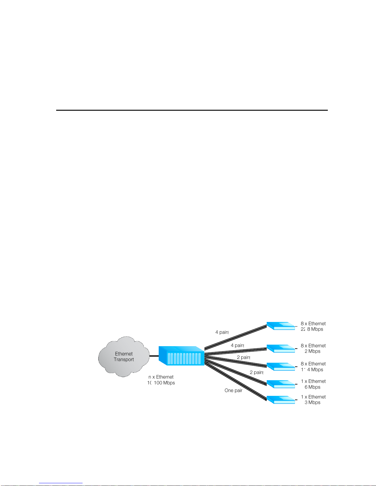
Figure 2-1 shows typical deployment scenarios of Watson Ethernet to deliver
Metro Ethernet Services:
Figure 2-1: Ethernet Services
Several Ethernet plug-in cards are installed in a subrack at the central office or
the point of presence. Depending on the service offered each plug-in can serve
between one and four customers. At the customer premises either a tabletop
Page 20
Watson Ethernet
Operating Manual
Watson-Ethernet-Manual.doc
Version 3.3-01
2-2
Revision: 2010-01-20
modem or a plug-in card in a tabletop housing is installed. Traffic from each customer is available at a dedicated Ethernet interface in the central office. Alternatively traffic from several customers can be aggregated to a single Ethernet port.
Advanced VLAN functions allow for customer isolation and traffic management.
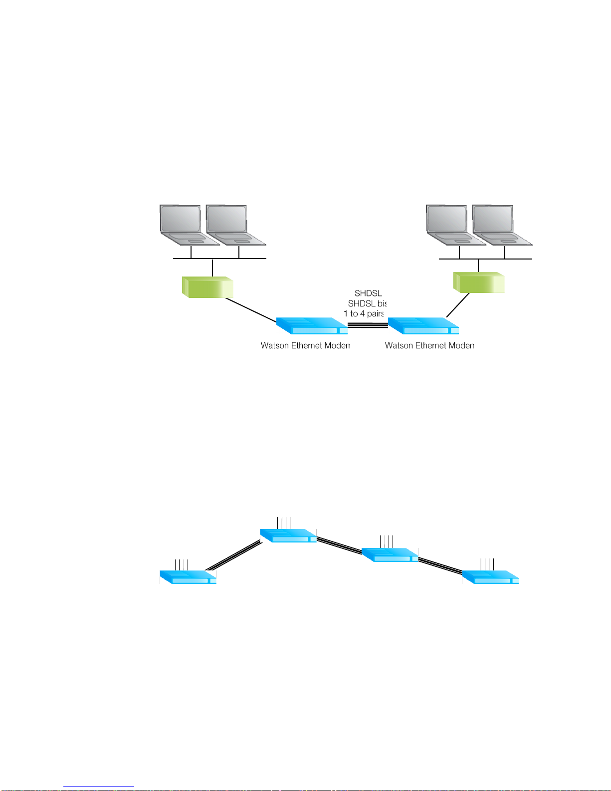
Watson Ethernet modems can also be used back-to-back as shown in Figure
2-2:
Figure 2-2: Campus Networks
For these applications either two tabletop modems or two plug-in modems (in an
appropriate housing) are connected back to back with one of the modems being
configured as DSL master and the other one as DSL slave. Depending on the
distance and the number of wire pairs available linerates up to 22.8 MBit/s are
available. VLAN and MAC Address filtering functions allow for traffic management and optimal use of the available DSL bandwidth.
Deployment in linear networks is supported with the Watson Ethernet plug-in
card:
Figure 2-3: Linear Ethernet Network
In Figure 2-3 several sites (e.g. stations along a pipeline or a power line) are
connected with single or two pair DSL systems. In each site a single Watson
Ethernet plug-in card terminates the DSL spans coming from "East" and "West"
sides and gives four local Ethernet interfaces e.g. to connect local station control
equipment. Traffic from the local interfaces can be aggregated with traffic on the
DSL and can be sent to either direction along the line. Traffic streams are kept
separate through VLANs, and Class of Service/Priority functions allow for traffic
management.
4
x Ethernet
10 / 100
Mbps
4
x Ethernet
10 / 100
Mbps
4
x Ethernet
10 / 100
Mbps G .
SHDSL
G . SHDSL
.
bis
4
x Ethernet
10 / 100
Mbps G .
SHDSL
G . SHDSL
.
bis
G . SHDSL
G . SHDSL
.
bis
Page 21
Watson-Ethernet-Manual.doc
Version 3.3-01
Watson Ethernet
Operating Manual
Revision: 2010-01-20
2-3
The entire chain can be managed from a centralized site through inband management.
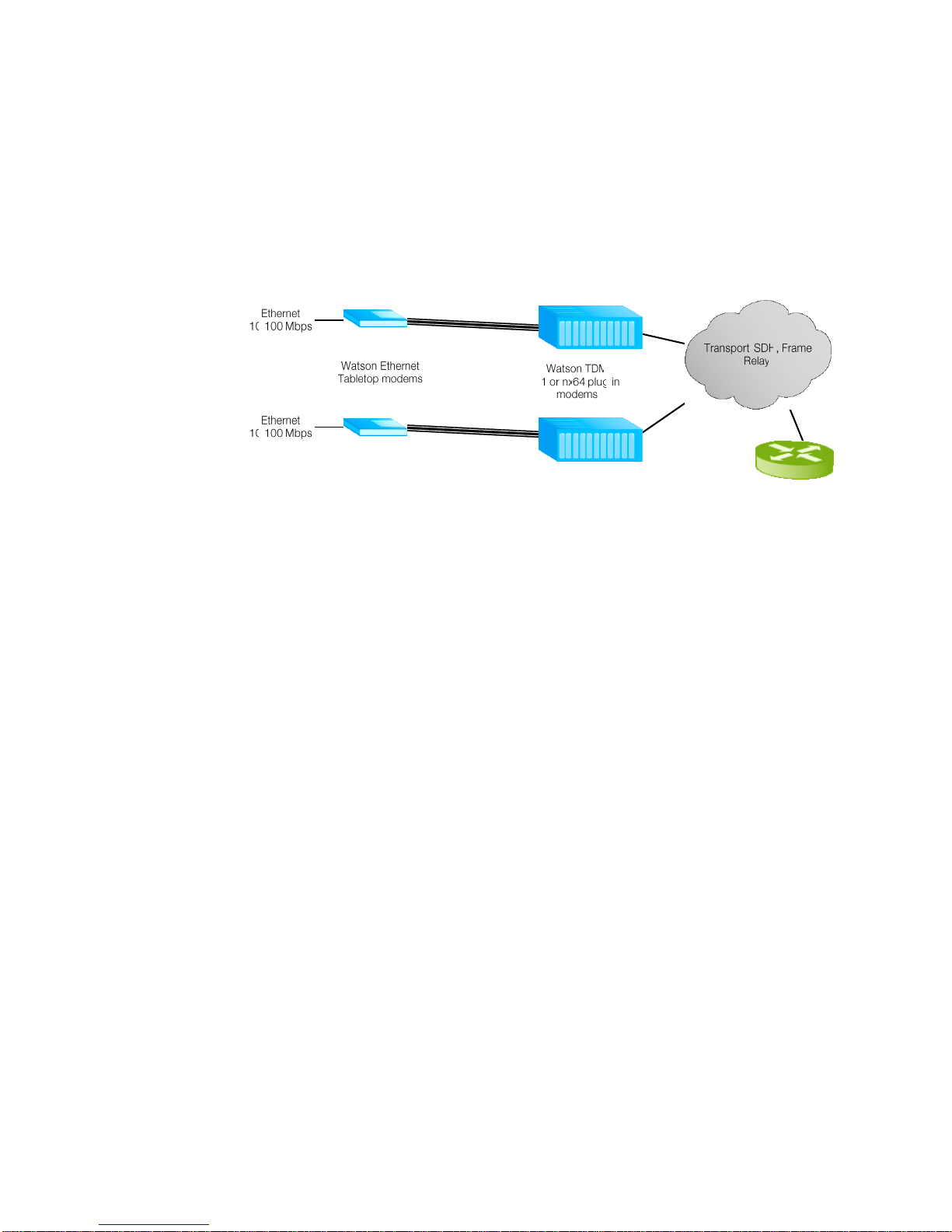
The Watson Ethernet tabletop modems can also be used together with Watson
TDM modems with E1 or nx64 user interfaces to transport Ethernet packets over
Wide Area Networks:
Figure 2-4: Ethernet over WAN
Here Watson Ethernet tabletop modems are installed at the customer premises
and Watson TDM modems in the central office. Ethernet packets are transported
transparently from one Watson Ethernet modem to the other. No intermediate
protocol conversion (e.g. ATM) is required to map Ethernet to the E1/SDH or
Frame Relay WAN. Instead of establishing a connection between two Watson
Ethernet tabletop modems the connection can also be terminated in the WAN
port of a router supporting the Cisco HDLC protocol.
Page 22

Page 23

Revision: 2010-01-20
3-1
3 Modem Features
3.1 DSL
3.1.1 Linerates and DSL sync rates
Watson Ethernet supports SDSL as specified in ETSI TS 101 524 and ITU-T
G.991.2. The linecode used is TC-PAM 16, the maximum linerate rate per pair is
2'306 kbit/s (36 timeslots with 64 kbit/s each).
The Watson Ethernet plug-in can be configured for the 2004 revision of ETSI TS
101 524, also known as eSDSL (ETSI) or G.SHDSL.bis (ITU-T). G.SHDSL.bis allows for higher symbol rates and a 32-level linecode (TC-PAM 32). The maximum number of timeslots per pair in G.SHDSL.bis is 89, the maximum linerate
rate per pair is 5'696 kbit/s.
There is some overlap between the linerates attainable in G.SHDSL and
G.SHDSL.bis:
16 TC-PAM
16 TC-PAM
32 TC-PAM
G.SHDSL, ETSI TS 101 524
G.SHDSL.bis, e-SDSL
5'696
Linerate
kBps
192
768 3'8402'304
Figure 3-1: G.SHDSL and G.SHDSL.bis linerates
This means that for certain linerates either TC-PAM 16 or TC-PAM 32 can be
configured in the modem. TC-PAM 16 has the better DSL performance than TCPAM 32. However with linerates rates higher than 2.3 MBit/s (36 timeslots) and
TC-PAM 16 the symbol rate over the DSL becomes higher than what was specified in the original version of TS 101 524. Higher symbol rates mean wider PSDs
which in turn can lead to higher interference to other DSL systems in the same
cable binder, e.g. ADSL, ADSL2, ADSL2+.
Page 24

Watson Ethernet
Operating Manual
Watson-Ethernet-Manual.doc
Version 3.3-01
3-2
Revision: 2010-01-20
The linerate rate, i.e. the data rate available to the application is calculated as follows:
893
41
64
pairpertimeslotsofnumbern
pairswireofnumberm
skbitnmLinerate
Note: n = 3 … 36 for the Watson Ethernet tabletop modem
The physical DSL synchronization rate per pair is
EOCskbitincludingskbitOverheadSHDSLOH
timeslotsofnumbern
skbitOHnSyncrate
238
893
64
Note: n = 3 … 36 for the Watson Ethernet tabletop modem
The sync rate determines the DSL reach. Decreasing the sync rate increases
DSL reach and vice versa. The linerate rate has no influence on the DSL reach.
3.1.2 Multipair operation
Watson Ethernet modems support multipair operation (m-wire mode). This allows for bandwidth aggregation of individual DSL wire pairs for higher speeds or
increased reach at a given speed.
Each wire pair of a multipair DSL span must be configured with the same linerate. If one pair of an m-wire span fails then the entire span must be restarted.
The following naming conventions are used in multipair operation on the Watson
Ethernet plug-in:
DSL spans are named DSL1, DSL2, DSL3 and DSL4. A span can consist of
one or several wire pairs. The number of DSL spans available on a plug-in
depends on the plug-in configuration (Monitor command CARDMODE).
Wire pairs within a span are named A, B, C and D. Depending on the number
of wire pairs within a span the wire pairs B, C or D might not exist.
Physical wire pairs available at the plug-in DSL connector are named a, b, c
and d.
Page 25

Watson-Ethernet-Manual.doc
Version 3.3-01
Watson Ethernet
Operating Manual
Revision: 2010-01-20
3-3
Depending of the operation mode of the Watson Ethernet plug-in (which is set by
the Monitor command CARDMODE, cf. 7.2.1) the following combinations are
possible:
CARDMODE
Spans
Wire
pairs
Connection Points
1
DSL1
DSL2
DSL3
DSL4
A
A
A
A
a1, a2
b1, b2
c1, c2
d1, d2
2
DSL1
DSL3
A, B
A, B
a1, a2, b1, b2
c1, c2, d1, d2
3
DSL1
DSL3
DSL4
A, B
A
A
a1, a2, b1, b2
c1, c2
d1, d2
4
DSL1
A, B, C, D
a1, a2, b1, b2 c1, c2, d1, d2
Table 3-1: Naming of DSL spans, pairs and connection points
3.1.3 Single-pair fallback
The Watson Ethernet plug-in supports single-pair fallback on multipair DSL
spans.
Should a failure occur on a multipair span then the modem will attempt to reconnect using one of the existing wire pairs; which one will be used is random.
The remaining spans are blocked and do not carry any traffic.
If a failure occurs on a fallback wire pair the modem will attempt to switch to
another of the wire pairs.
The single-pair fallback mode is cleared by issuing a RESET DSLx Monitor
command.
Single-pair fallback can be enabled/disabled with the FALLBACK Monitor command and by SNMP.
Notes:
Single-pair fallback is only supported between two plug-in modems
The fallback process is controlled by the STU-C modem. The STU-R adapts
automatically to fallback and does not need any configuration..
Page 26

Watson Ethernet
Operating Manual
Watson-Ethernet-Manual.doc
Version 3.3-01
3-4
Revision: 2010-01-20
3.1.4 Power Backoff
The transmit power of the modems can be decreased by activating the power
back-off mode. This reduces interference to other transmission systems operating on adjacent pairs bundled in the same cable.
With enabled power back-off the transmit power will be reduced adaptively in
function of the estimated cable attenuation:
Estimated Power
Loss(*)
Power Backoff
< 1 dB
6 dB
< 2 dB
5 dB
< 3 dB
4 dB
< 4 dB
3 dB
< 5 dB
2 dB
< 6 dB
1 dB
6 dB
no backoff
(*) Calculated as Tx Power –
Estimated Rx Power
Table 3-2: Power Backoff
Note:
Power backoff can be configured individually for plug-in and tabletop.
3.1.5 Symmetric and Asymmetric PSDs
The Watson Ethernet tabletop modems support asymmetric PSDs for linerates
of 2'056 kbit/s and 2'312 kbit/s.
Activating asymmetrical PSD masks will increase upstream transmit power (STUR STU-C). This improves near-end crosstalk (NEXT) at the STU-C side and
will increase the possible loop length in cases where many DSL spans have to
share the same cable e.g. coming out of a central office.
Note:
The Watson Ethernet plug-in and the Watson SHDSL Router do not support
asymmetric PSDs.
3.1.6 DSL Performance Parameters
The Watson Ethernet modems provide information about the current Signal
Quality and Attenuation of a DSL span.
Signal Quality
The Signal Quality is the noise margin calculated by the modem:
SQ = SNR1 - SNR0
Where
SQ is the calculated noise margin
SNR1 is the signal to noise ratio calculated by the transceiver by analyzing
the error correction bits (Trellis bits) in the line code.
Page 27

Watson-Ethernet-Manual.doc
Version 3.3-01
Watson Ethernet
Operating Manual
Revision: 2010-01-20
3-5
SNR0 is the signal to noise ratio that gives a bit error rate of 10
-7
in presence of average white Gaussian noise. For TC-PAM16 the theoretical
value for SNR0 is 27.7 dB.
Attenuation
The link attenuation is calculated by the modem assuming 0.4mm PE cable without bridged taps and measured at 150 kHz (for linerates of 200 kbit/s up to 1'992
kbit/s) or 200 kHz (for linerates of 2'056 kbit/s and above). This calculated attenuation may differ from the attenuation measured by other equipment for other
cable configurations (other cable diameter, splices, bridged taps).
Both Signal Quality and Attenuation are effective maintenance tools for determining inadequate or bad cable pairs. They are available with the DIAGNOSTIC
Monitor command.
Page 28
Watson Ethernet
Operating Manual
Watson-Ethernet-Manual.doc
Version 3.3-01
3-6
Revision: 2010-01-20
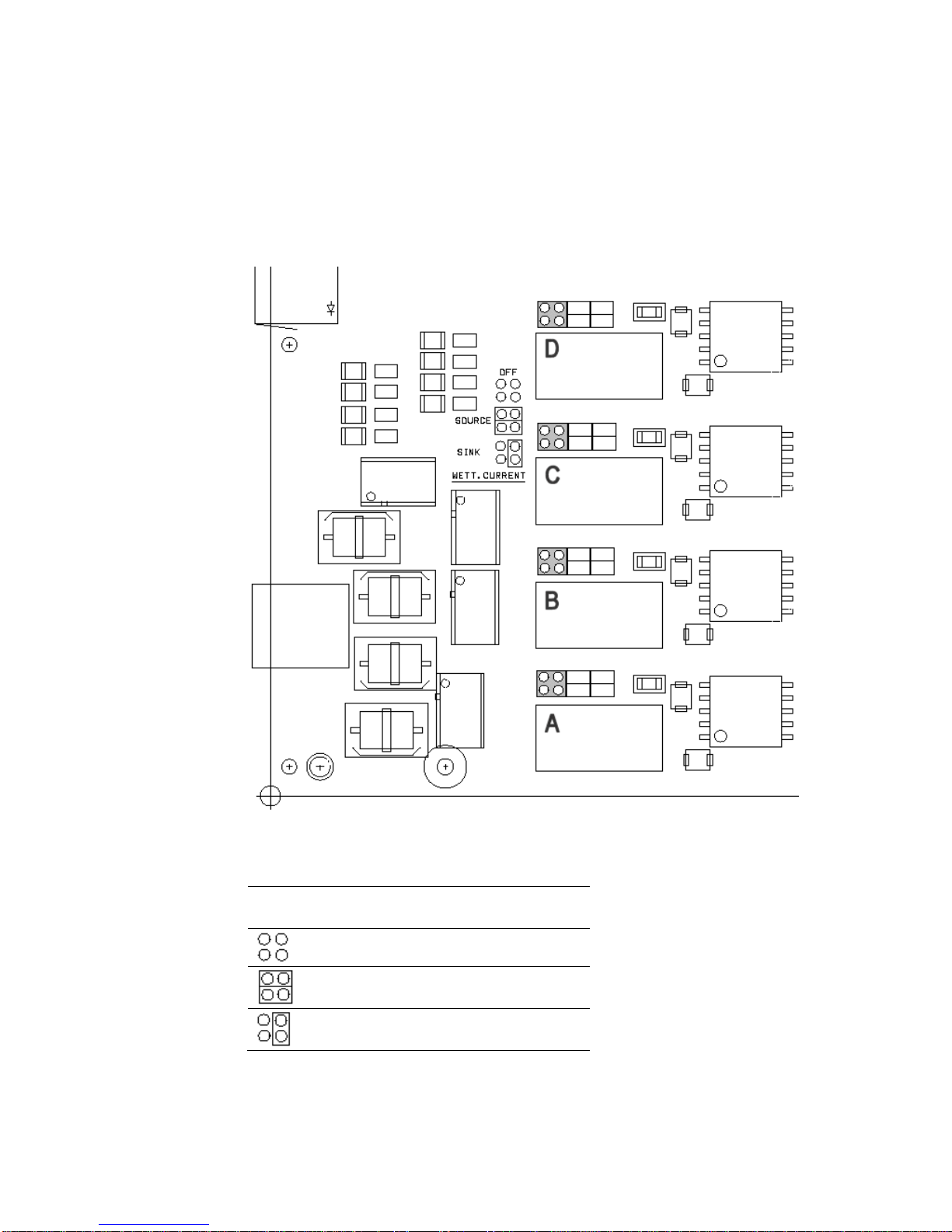
3.1.7 Wetting Current
The Watson Ethernet plug-in can source or sink wetting current over the DSL
line. Wetting current is configured per wire pair by jumpers located on the lower
left corner of the plug-in:
Figure 3-2: Wetting current jumper location
Jumper Configuration
Wetting Current
Function
(no jumpers)
Wetting current off
(two jumpers)
Wetting current source
(one jumper)
Wetting current sink
Table 3-3: Wetting current jumper settings
The Watson Ethernet tabletop modems cannot source wetting current. It will always sink wetting current when local powering is used.
Page 29
Watson-Ethernet-Manual.doc
Version 3.3-01
Watson Ethernet
Operating Manual
Revision: 2010-01-20
3-7
3.1.8 Master / Slave
To start up a DSL span, one system unit must be configured as master modem
(STU-C) and the other one as slave (STU-R). The master controls the span startup procedure. If both system units are configured as master or as slave, no startup will occur.
Usually, the plug-in is configured as master and the tabletop modem as slave
(default setting). However, it is possible to set up a DSL span between two plugins or two tabletops, as long as one is configured as master and the other one as
slave.
3.1.9 DSL Clocking
Watson Ethernet modems have a crystal controlled DSL clock that does not depend on the clocking of the Ethernet user interfaces (clockmode 1 of TS 101
524).
3.2 Ethernet (plug-in modem)
3.2.1 Ethernet over DSL
Ethernet packets are mapped on the DSL frame using the packet mode TPS-TC
layer of ETSI TS 101 524. The modems use bit stuffing to improve efficiency.
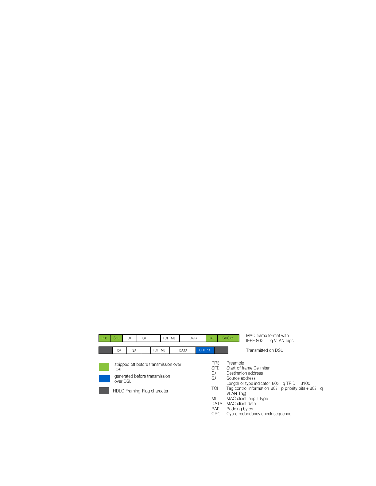
The Ethernet MAC-frames are reformatted before being transmitted over the
DSL span:
Preamble (PRE), Start-of-Frame delimiter (SFD) and PAD fields are stripped
off
The Ethernet CRC-32 is replaced by a CRC-16 calculated over all fields of
the MAC frame
PRE, SFD, an eventual PAD and the CRC-32 are reconstructed by the receiving
modem before transmitting the MAC frame over its Ethernet interface.
Figure 3-3: Ethernet over DSL
Page 30
Watson Ethernet
Operating Manual
Watson-Ethernet-Manual.doc
Version 3.3-01
3-8
Revision: 2010-01-20
3.2.2 Ethernet Bridging
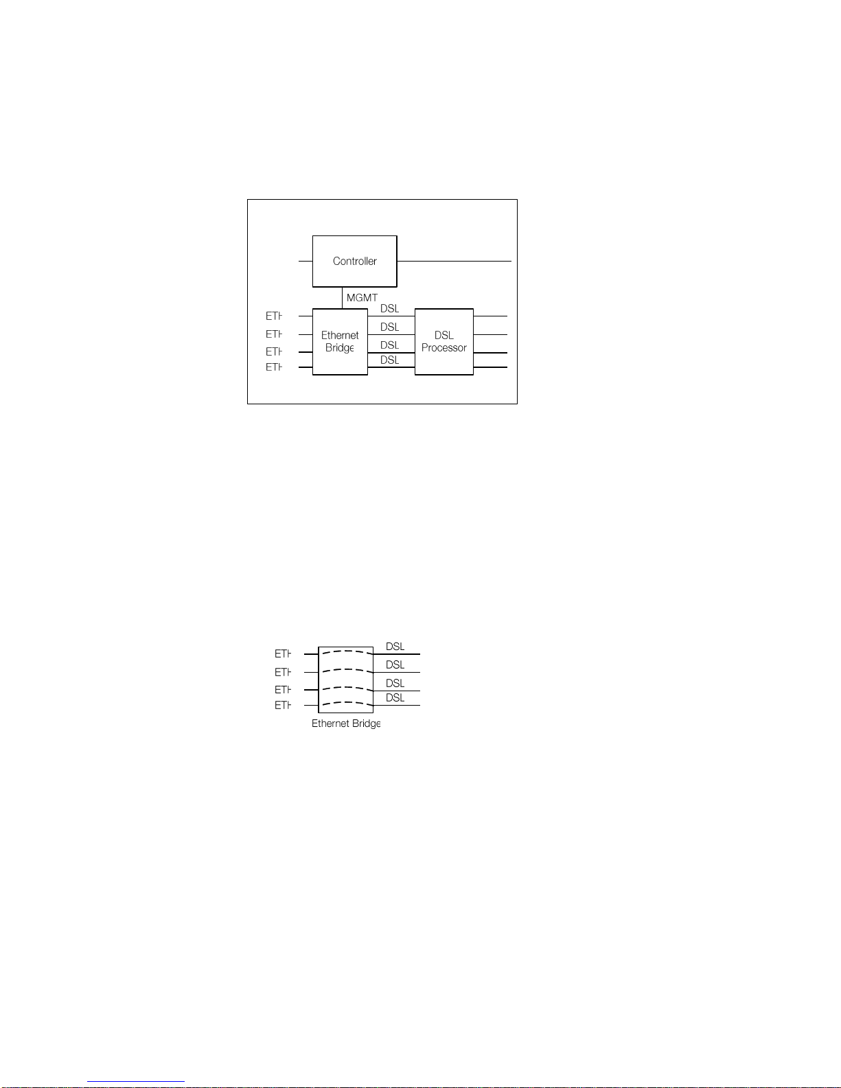
The Watson Ethernet plug-in card has a built-in Ethernet bridge that connects
Ethernet ports, DSL spans and the plug-in controller:
Figure 3-4: Watson Ethernet plug-in Block diagram
The Ethernet bridge supports the following modes
1) VLAN bridging. Layer 2 VLANs are used to control the traffic. For an Ethernet
packet to be sent from one port to another both ports must be configured to
be in the same VLAN. This bridging mode allows that Ethernet user interfaces can be switched to DSL interfaces and vice versa. It is also possible to
switch packets from several DSL interfaces to one Ethernet interface (concentration), to switch packets from an Ethernet or DSL interface to the Management Processor interface MGMT3 (used for inband management) or to
switch packets from DSL to DSL interface.
2) Transparent bridging. In this mode there is a fixed association between DSL
and Ethernet bridge ports:
Figure 3-5: Transparent bridging
Transparent bridging is similar to the VLAN transparency provided by the
Watson Ethernet tabletop modem, cf. 3.3.2. Transparent bridging lacks the
flexibility of VLAN bridging, and inband management or linear networks are
not supported in this mode. The advantage of transparent bridging is that it is
not required to configure any VLAN tags on the bridge, any VID received on
an Ethernet port will be relayed to the corresponding DSL span and vice versa.
Note that the association between Ethernet and DSL spans is independent of
the currently configured multipair mode of the DSL spans. If for example all
four DSL wire pairs are combined to a single DSL span (DSL1) then Ethernet
port ETH1 will be associated with DSL span DSL1 while ports ETH2 .. ETH4
and DSL2 .. DSL4 do not carry any traffic at all.
Page 31

Watson-Ethernet-Manual.doc
Version 3.3-01
Watson Ethernet
Operating Manual
Revision: 2010-01-20
3-9
3) Transparent bridging with inband management. This mode is equivalent to
the Transparent bridging mode but allows inband management through the
DSL spans, cf. 3.5.5.
The bridging modes are controlled by the BRIDGEMODE Monitor command.
3.2.3 MAC Defect Signaling
The operating status of DSL Spans and remote Ethernet interfaces can be linked
to the status of the local Ethernet interfaces through MAC Defect Signaling
(MDS).
If MDS is active then the Ethernet User Interfaces will be disabled if
the DSL span is not synchronized OR
the Ethernet User interface at the remote end is not active (LKINT alarm from
the remote side)
There is a fixed association between DSL spans and Ethernet interfaces for MDS
(DSL1 is associated with ETH1, DSL2 with ETH2 etc.). This association is independent of the currently configured BRIDGEMODE.
MDS can be enabled and disabled individually per Ethernet interface with the
MDS Monitor command.
3.2.4 VLANs
The Watson Ethernet plug-in supports VLAN functions according to IEEE
802.1q. Each of the Ethernet bridge ports (ETH1 .. ETH4, DSL1 .. DSL4,
MGMT3) can be member of one or several VLANs. The maximum number of
VLANs is 64. Each VLAN has a VLAN Identifier (VID) between 1 and 4094.
Upon reception of an Ethernet packet at a port its VID is checked against the
VIDs of all VLANs this port is a member of. Packets that do not carry one of
these VIDs will be discarded.
For untagged packets the default VID for the port is used to determine VLAN
membership.
Packets are only forwarded to ports that are a member of the VLAN of this packet.
Upon transmission the packet will be tagged with the VLAN tag originally received. If the packet was untagged then the default tag of the receiving port is
added to the packet. The port can also be configured to send the packets untagged.
3.2.5 VLAN Examples
VLANs are always used within the Watson Ethernet plug-in to segregate traffic
from different ports. This is true even when no VLAN tags are present on packets
ingressing or egressing the plug-in.
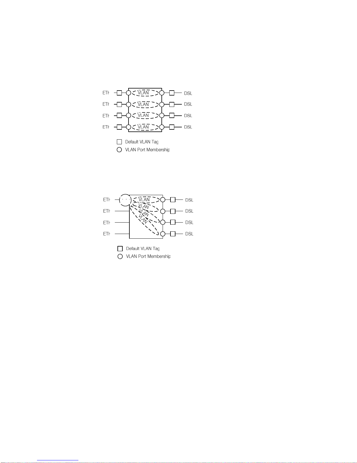
Figure 3-6 below shows a simple VLAN configuration example. Both on the DSL
and on the Ethernet side untagged packets are used. On the Watson Ethernet
plug-in four VLANs (VLAN 1, VLAN 2, VLAN 3 and VLAN 4) are configured. Depending on its ingress port each packet gets a default tag between 1 and 4. This
tag is then used to switch the packet to the correct egress port, effectively con-
Page 32
Watson Ethernet
Operating Manual
Watson-Ethernet-Manual.doc
Version 3.3-01
3-10
Revision: 2010-01-20
necting ETH1 to DSL1, ETH2 to DSL2 etc. while blocking all traffic between
Ethernet ports and between DSL spans. The VLAN configuration of Figure 3-6 is
automatically activated when issuing the DEFAULT 2 Monitor command.
Figure 3-6: Simple VLAN Example
Figure 3-7 shows how the VLAN switching function can be used for traffic concentration:
Figure 3-7: VLAN configuration for traffic concentration
In this example four independent DSL customers are concentrated to a single
Ethernet trunk interface. On the DSL lines untagged packets are used. Upon ingress into the Watson Ethernet plug-in the packets get a default VLAN tag between 1 and 4 based on their ingress port. All traffic is switched to port ETH1
which is member of all four VLANs. The packets egress the Watson Ethernet
plug-in with VLAN tags, allowing to separate traffic streams from the four DSL
spans different customers. Ports ETH2 .. ETH4 are unused in this scenario.
Page 33
Watson-Ethernet-Manual.doc
Version 3.3-01
Watson Ethernet
Operating Manual
Revision: 2010-01-20
3-11
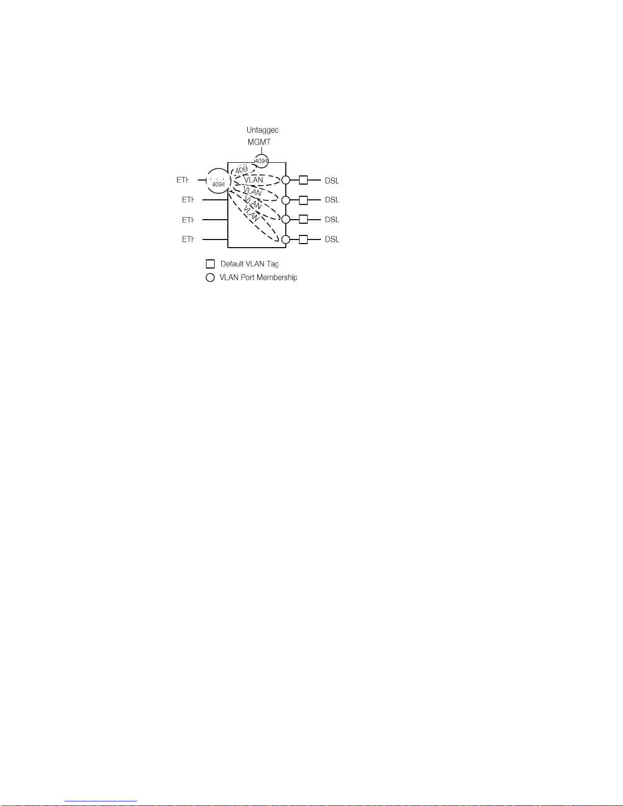
Figure 3-8 shows how Ethernet user interfaces are used for inband management:
Figure 3-8: VLAN configuration for Inband Management
For user traffic we have the same configuration as in Figure 3-7. However we
have added one additional VLAN 4094 which is used for inband management.
Ports ETH1 and MGMT3 are members of this VLAN. Because the DSL spans
are not member of VLAN 4094 management traffic is isolated from user traffic
and there is no access to management function through the DSL spans.
Note that port MGMT3 must use untagged packets to properly interface with the
card controller. Management packets coming from the card controller are tagged
with VLAN 4094 upon ingress into the bridging function.
3.2.6 Individual and shared forwarding databases
VLANs can have individual or shared forwarding databases (IVL or SVL operation). The Watson Ethernet plug-in supports 16 separate forwarding databases
which can be freely assigned to VLANs. Address learning is always done based
on MAC addresses without taking VIDs into account.
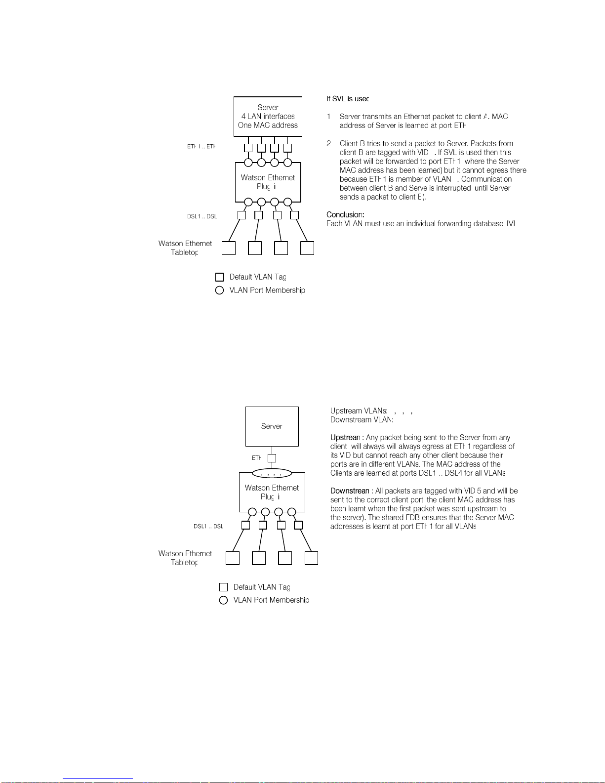
IVL is required e.g. if a single server is connected to several Ethernet user ports
on different VLANs and all of the server interfaces use the same MAC address.
In this case the server MAC address will appear to move between Ethernet ports
and VLANs depending upon which interface has most recently transmitted a
frame. Communication to the server will be disrupted
Page 34
Watson Ethernet
Operating Manual
Watson-Ethernet-Manual.doc
Version 3.3-01
3-12
Revision: 2010-01-20
Figure 3-9: Individual VLAN learning (IVL) example
For IVL operation each VLAN must be configured to use an own forwarding database. This is done by specifying individual forwarding database identifiers
(FIDs) per VLAN in the VLANCREATE Monitor command.
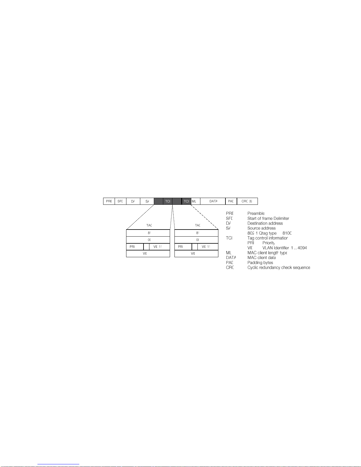
SVL is used e.g. in asymmetric VLAN configurations. Asymmetric VLANs together with Port-based tagging allow several clients to access a common server while
prohibiting the clients from talking to each other:
Figure 3-10: Shared VLAN learning (SVL) example
For SVL operation several VLANs are configured to use the same forwarding database.
Page 35
Watson-Ethernet-Manual.doc
Version 3.3-01
Watson Ethernet
Operating Manual
Revision: 2010-01-20
3-13
Notes:
The Watson Ethernet tabletop modems are transparent to VLANs, i.e. VLAN
tags are preserved during transmission over the DSL.
The Watson Ethernet tabletop modem has a single address learning data-
base which does not take VIDs into account.
3.2.7 Stacked VLANs
The Watson Ethernet plug-in also supports double-tagged VLANs (a.k.a stacked
VLANs). Stacked VLANs is a method to increase the number of available VIDs in
a structured and hierarchical fashion that is backward-compatible with singletagged VLANs as long as the network supports packet sizes of 1'526 bytes or
more.
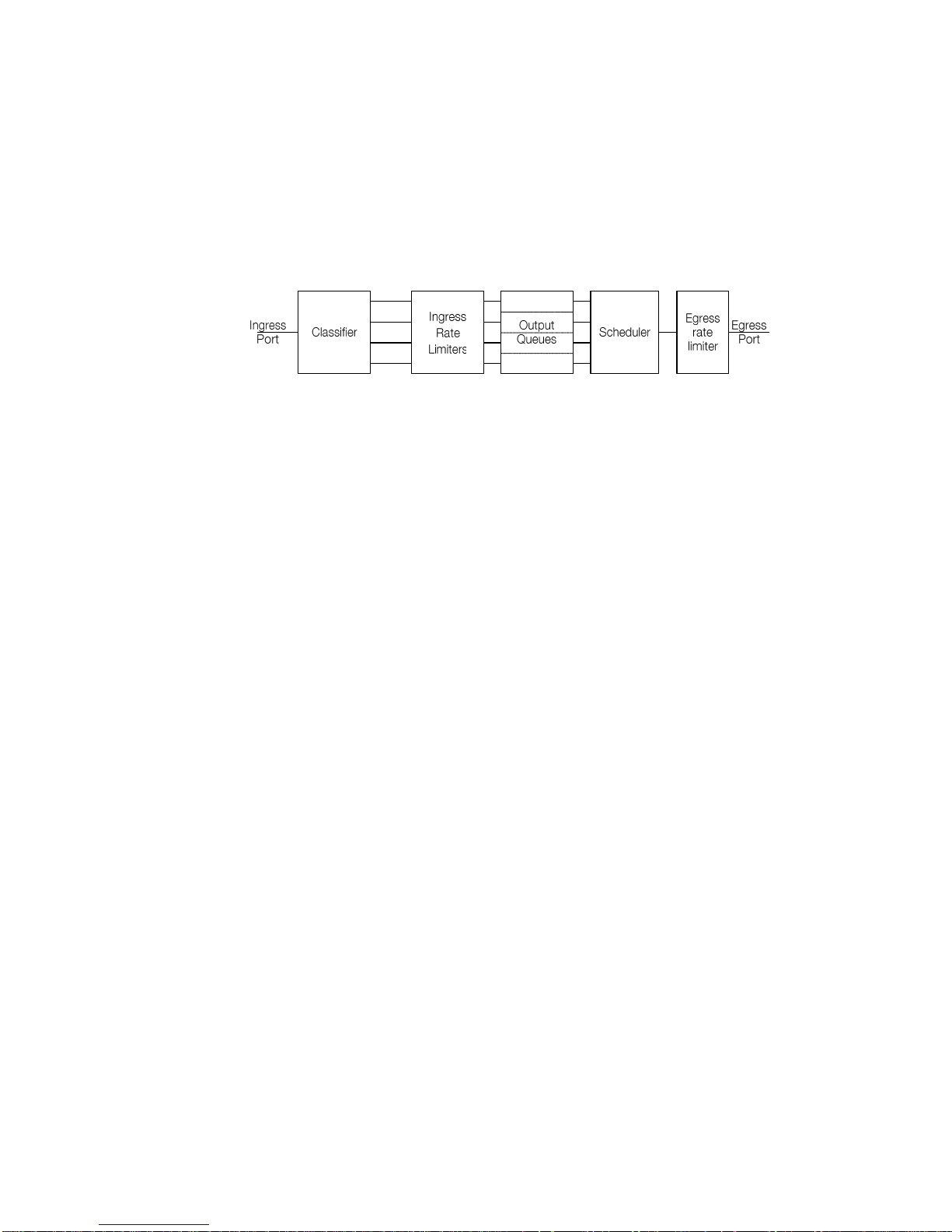
This method places an extra tag (often referred to as the S-TAG or Service Provider Tag) in front of the first tag (known as the C-TAG or Customer Tag). The
double tag format is shown in Figure 3-11.
Figure 3-11: Stacked VLAN frame format
Each port can be configured for double tagging in incoming (ingress) and outgoing (egress) direction. Normally ingress and egress double tagging are
enabled simultaneously.
A port with ingress double tagging enabled expects double tagged frames. The
port will remove the outer tag. If a frame contains only a single tag then this tag
will be removed. Untagged frames are not modified.
After removal of the outer tag the Ethernet bridge will process the packet as a
single-tagged VLAN packet, cf. 3.2.3. For packets with a single tag or no tag the
default tag for this port will be used to determine VLAN membership and possible
egress ports.
A port with egress double tagging enabled will transmit all packets with an extra
outer tag. When the packet had no tag, it will be sent with a single tag. When the
packet had a single tag, it will egress double-tagged. The tag added is the default tag of the source port of the packet.
Note:
The tabletop modems support frame sizes of 2’048 bytes and are transparent to
double-tagged Ethernet packets.
Page 36
Watson Ethernet
Operating Manual
Watson-Ethernet-Manual.doc
Version 3.3-01
3-14
Revision: 2010-01-20
3.2.8 Class of Service (CoS)
The Watson Ethernet plug-in supports differentiated treatment of Ethernet packets according to their class of service. The plug-in supports four different classes
named Q1 .. Q4 (Q4 is the highest priority queue, Q1 has lowest priority), classification based on layer 2 or layer 3 information and ingress as well as egress rate
limiting.
Figure 3-12: Class of Service functions
When a packet enters the Watson Ethernet plug-in its priority is be classified either by layer 2 information (IEEE 802.1p bits in the VLAN tag) or by layer 3 information (DSCP in the IP header). The packet is then associated with one of the
priority levels.
On ingress each priority level can be individually rate limited according to the following rules:
Q1 can be limited to 128 kbps, 256 kbps, 512 kbps, 1'024 kbps, 2'048 kbps,
4'096 kbps or 8'192 kbps
Each higher priority level can be rate limited either to the same rate as the
next lower priority level or to twice as much.
Page 37

Watson-Ethernet-Manual.doc
Version 3.3-01
Watson Ethernet
Operating Manual
Revision: 2010-01-20
3-15
Table 3-4 shows of all possible rate combinations (k kbit/s, M MBit/s):
Profile
Q1
Q2
Q3
Q4
Profile
Q1
Q2
Q3
Q4
1
128k
128k
128k
128k
2
128k
128k
128k
256k
3
256k
256k
256k
256k
4
256k
256k
256k
512k
5
512k
512k
512k
512k
6
512k
512k
512k
1M 7 1M
1M
1M
1M 8 1M
1M
1M
2M 9 2M
2M
2M
2M
10
2M
2M
2M
4M
11
4M
4M
4M
4M
12
4M
4M
4M
8M
13
8M
8M
8M
8M
14
8M
8M
8M
16M
15
128k
256k
256k
256k
16
128k
256k
256k
512k
17
256k
512k
512k
512k
18
256k
512k
512k
1M
19
512k
1M
1M
1M
20
512k
1M
1M
2M
21
1M
2M
2M
2M
22
1M
2M
2M
4M
23
2M
4M
4M
4M
24
2M
4M
4M
8M
25
4M
8M
8M
8M
26
4M
8M
8M
16M
27
8M
16M
16M
16M
28
8M
16M
16M
32M
29
128k
128k
256k
256k
30
128k
128k
256k
512k
31
256k
256k
512k
512k
32
256k
256k
512k
1M
33
512k
512k
1M
1M
34
512k
512k
1M
2M
35
1M
1M
2M
2M
36
1M
1M
2M
4M
37
2M
2M
4M
4M
38
2M
2M
4M
8M
39
4M
4M
8M
8M
40
4M
4M
8M
16M
41
8M
8M
16M
16M
42
8M
8M
16M
32M
43
128k
256k
512k
512k
44
128k
256k
512k
1M
45
256k
512k
1M
1M
46
256k
512k
1M
2M
47
512k
1M
2M
2M
48
512k
1M
2M
4M
49
1M
2M
4M
4M
50
1M
2M
4M
8M
51
2M
4M
8M
8M
52
2M
4M
8M
16M
53
4M
8M
16M
16M
54
4M
8M
16M
32M
55
8M
16M
32M
32M
56
8M
16M
32M
64M
Table 3-4: Ingress rate limiter profiles
Each combination of rates is associated with a profile number. This profile number is used in the RATELIMIT IN Monitor command to configure a particular
combination of rates.
Note that the ingress rate limits are overlap and non-cumulative. The aggregate
bandwidth of Q1 .. Q4 is limited by the maximum bandwidth of Q4. Figure 3-13
shows the bandwidth allocation for ingress profile 50:
Page 38
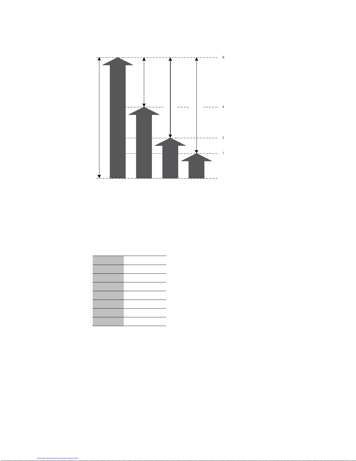
Watson Ethernet
Operating Manual
Watson-Ethernet-Manual.doc
Version 3.3-01
3-16
Revision: 2010-01-20
Figure 3-13: Ingress rate limiter example
After classification and rate limiting, the packets are sent to their output queues.
A scheduler will schedule packets according to their priorities and send them to
the egress port. The scheduler can be configured to work either in strict priority
mode or in weighted fair queuing mode with fixed weights 8:4:2:1 for
Q4:Q3:Q2:Q1 respectively. Scheduling policy is a global setting and affects all
ports simultaneously.
Finally the egress port can be rate limited according to the following profiles:
Profile
Rate
8
23.5M
7
11.8M
6
5.9M
5
2.9M
4
1.5M
3
734.4k
2
367.2k
Table 3-5: Egress rate limiter profiles
The profile number is used in the RATELIMIT OUT command to configure a particular egress rate. Only the entire port after scheduling can be rate limited, there
are no individual queues at this stage.
Note:
CoS functions are not available on the Watson Ethernet tabletop modems.
3.2.9 Spanning Tree Protocol
The Watson Ethernet plug-in modems support the Rapid Spanning Tree (RSTP)
protocol according to IEEE 802.1D-2004.
Page 39

Watson-Ethernet-Manual.doc
Version 3.3-01
Watson Ethernet
Operating Manual
Revision: 2010-01-20
3-17
The spanning tree network protocol provides a loop free topology for any bridged
LAN. It detects/disables network loops and provides backup links between
bridges. If a loop is detected then the protocol blocks one or more redundant
ports.
The bridges continually exchange information. When they recognize a change in
network topology then RSTP automatically reconfigures bridge ports to avoid
network failure.
Bridge Protocol Data Units (BPDUs)
The bridges in a network continuously exchange RSTP information carried in
special frames called bridge protocol data units (BPDUs). BPDUs are exchanged
regularly at configurable intervals (the Hello time, 2 seconds by default) and enable bridges to keep track of network changes and activate or disable ports as required.
Topology Change Notification (TCN) BPDUs are used to inform other bridges of
port changes. TCNs are injected into the network by a non-root bridge and propagated to the root. Upon reception of the TCN the root bridge will set a Topology
Change flag in its normal BPDUs. This flag is propagated to all other bridges to
instruct them to rapidly age out their forwarding table entries.
Port states
Each port on a bridge can be in one of three states:
Learning - the port processes BPDUs and awaits possible new information
that would cause it to return to the blocking state. While the port does not yet
forward frames it does learn source addresses from frames received and
adds them to the filtering database.
Blocking – the port processes BPDUs but discards all other frames.
Forwarding – the port forwards frames and processes BPDUs.
When a bridge port is initialized it will not immediately start to forward frames. It
will instead go into the Learning state while it processes BPDUs and determines
the topology of the network.
The port will go into Forwarding state after expiry of a timer (the forwarding delay
timer) unless RSTP determines that this port would cause a loop in the network.
In this case the port will transition to Blocking state.
RSTP Protocol operation
Root bridge election: one bridge in the network is selected as the root bridge.
The root bridge is the root of the tree spanning the entire network once the
RSTP has converged.
Selection is based on the Bridge Identifier (BID) which uniquely identifies
each bridge. A BID is composed of a configurable bridge priority and the
MAC address of the bridge. BPDU exchange results in the bridge with the
numerically lowest BID to be selected as root bridge.
The bridge priority is normally left at its default value (32768) but can be reconfigured to a lower number if the network administrator wishes a particular
bridge to be elected as root bridge.
Page 40

Watson Ethernet
Operating Manual
Watson-Ethernet-Manual.doc
Version 3.3-01
3-18
Revision: 2010-01-20
Root port determination: each non-root bridge designates one root port. The
root port is the port through which this non-root bridge communicates with the
root bridge.
The root port is the port on the non-root bridge with the lowest path cost
(measured as sum the costs of all paths traversed to the root) to the root
bridge. The root port is in Forwarding state.
Designated port determination: for each LAN segment (collision domain) the
RSTP configures one Designated port. The Designated port is the port on
this segment that has the lowest path cost to the root bridge. If more than
one port in the segment have the same path cost, the port of the bridge with
the lowest bridge ID is selected as a Designated port.
Designated ports are set to Forwarding state, all other ports are in Blocking
state.
Edge Ports
Ports which are known to be at the edge of the network i. e. not connected to
any other bridge can be configured as edge ports. Edge ports will immediately
transition into forwarding state since there is no possibility of it participating in a
loop.
Note that configuring a non-edge port as edge port might create loops in the
network. Any port configured as edge port will automatically revert to non-edge
configuration if a BPDU is received on this port.
Point-to-point ports
Ports which connect to exactly one other bridge (no shared media) can be configured as point-to-point ports. Point-to-point ports can signal to the neighboring
bridge their desire to be Designated and Forwarding. Upon explicit acknowledgement from the neighboring bridge these ports can transition directly Into forwarding state without waiting for a timer expiry.
Path cost
Path cost is the total cost of transmitting a frame on to a LAN through that port to
the root bridge. This is the sum of the costs of each LAN segment or link along
the path.
Cost values are configured according to the bandwidth of the link. The slower the
media, the higher the cost.
Recommended cost values are:
Link Speed
Recommended Cost
Recommended Cost Range
1 Mbps
20'000'000
2'000'000 – 200'000'000
2 Mbps
10'000'000
1'000'000 – 100'000'000
4 Mbps
5'000'000
500'000 – 50'000'000
8 Mbps
2'500'000
250'000 – 25'000'000
10 Mbps
2'000'000
200'000 – 20'000'000
100 Mbps
200'000
20'000 – 2'000'000
Table 3-6: Recommended port cost values
Page 41

Watson-Ethernet-Manual.doc
Version 3.3-01
Watson Ethernet
Operating Manual
Revision: 2010-01-20
3-19
Performance parameters
The operation of the RSTP is controlled by a set of configurable performance parameters:
Hello Time: the interval between periodic transmissions of configuration mes-
sages by Designated ports. Configurable with the STP HELLO Monitor command.
Maximum Age: maximum age of a BPDU before it is discarded. The age of a
BPDU is incremented by one on each traversal through a bridge.
A bridge port that was disabled (e.g. through a reset or a link integrity failure)
will wait Maximum Age seconds before transiting into Learning state. The
Maximum Age parameter is controlled with the STP MAXAGE Monitor command.
Forwarding Delay timer: the delay used by the bridge in STP mode to transi-
tion Root and Designated Ports to Forwarding (this transition will take maximum Hello Time seconds in RSTP mode). Set with the STP FORWARD Monitor command.
The following relationships are enforced by the Watson Ethernet plug-in:
2 (Forward-Delay-Timer – 1.0 seconds) Maximum-Age-Timer
Maximum-Age-Timer 2 (Hello-Time + 1.0 seconds)
Transmit Hold Count: the maximum number of bridging protocol data units
(BPDUs) transmitted per second. Controlled with the STP TXHOLD Monitor
command.
3.3 Ethernet (tabletop modem)
3.3.1 Ethernet over DSL
The Watson Ethernet tabletop modem uses the same HDLC procedure to transport Ethernet frames over DSL as the Watson Ethernet plug-in modem. Cf. 3.2.1
3.3.2 VLAN features
The Watson Ethernet tabletop modem is transparent for VLAN tags according to
IEEE 802.1p/q.
A default VLAN tag can be added to packets without VLAN tags.
In double tagging mode a second VLAN tag is supported.
Page 42
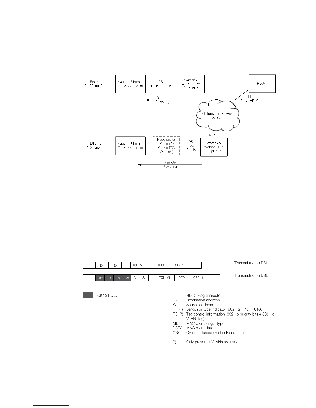
Watson Ethernet
Operating Manual
Watson-Ethernet-Manual.doc
Version 3.3-01
3-20
Revision: 2010-01-20
3.3.3 Mixed mode operation
The Watson Ethernet tabletop modems are interoperable with other Watson
TDM modems:
Figure 3-14: Mixed mode operation
One pair and two pair links are supported in mixed mode operation. The maximum throughput is 2.048 Mbps (32 timeslots) in E1 mixed mode operation and
9.9 Mbps (156 timeslots) in nx64 mixed mode operation. In mixed mode opera-
tion the Watson Ethernet tabletop modems can be remotely powered from the
E1 or nx64 plug-ins. The Watson Regenerator is supported.
3.3.4 Cisco HDLC
The Watson Ethernet tabletop modems support "Cisco HDLC" formatting described in RFC 1547 with 16-bit FCS and bit-stuffed framing. Use Cisco HDLC in
mixed mode operation (Figure 3-14) to directly connect the remote end of the link
to the WAN port of a router.
HDLCTAG OFF
HDLCTAG ON
Figure 3-15: Cisco HDLC
The Cisco HDLC formatting is controlled with the HDLCTAG Monitor command.
Page 43

Watson-Ethernet-Manual.doc
Version 3.3-01
Watson Ethernet
Operating Manual
Revision: 2010-01-20
3-21
3.4 Firmware update
3.4.1 Plug-in
Firmware of the Watson Ethernet plug-in can be updated remotely using the
TFTP protocol. To load a new firmware package into a plug-in, copy the package
on the TFTP server and use the UPDATE GET Monitor command to load the new
package into the plug-in.
Once the new package is loaded in it must be activated. This is done with the
UPDATE COMMIT command. The plug-in will automatically reboot to activate the
new firmware package.
If there are any problems with the newly loaded firmware package then it is possible to revert to the last installed package using the UPDATE REVERT command.
3.4.2 Tabletop
The Watson Ethernet tabletop firmware can be upgraded either through the local
RS-232 monitor port or remotely from a Watson Ethernet plug-in modem through
the DSL span.
In the first case a PC with the Watson Flashloader application [10] must be used
to load a new firmware package into the tabletop. This PC must be connected
the RS-232 interface of the tabletop modem.
In the second case a new firmware package can be transferred into the tabletop
through the DSL span and the Watson Ethernet plug-in using the TFTP protocol.
This is controlled by the DOWNLOAD Monitor command, cf. 7.5.4.
3.5 Management
3.5.1 Management interfaces
Watson Ethernet modems have several management possibilities:
Management through a local RS-232 port using a command line interface
(Monitor)
DSL slave modems (STU-R) can be managed inband through the DSL EOC
from the DSL master modem.
The Watson Ethernet plug-in modem has a dedicated Ethernet interface (Q –
Interface) for remote management through Telnet or SNMP.
SNMP and Telnet management are also available through the Ethernet user
interfaces of the Watson Ethernet plug-in modem (Ethernet inband management). Normally a dedicated management VLAN is used in this case.
Ethernet inband management is also possible through a DSL span that is
terminated by a Watson Ethernet plug-in modem.
Page 44
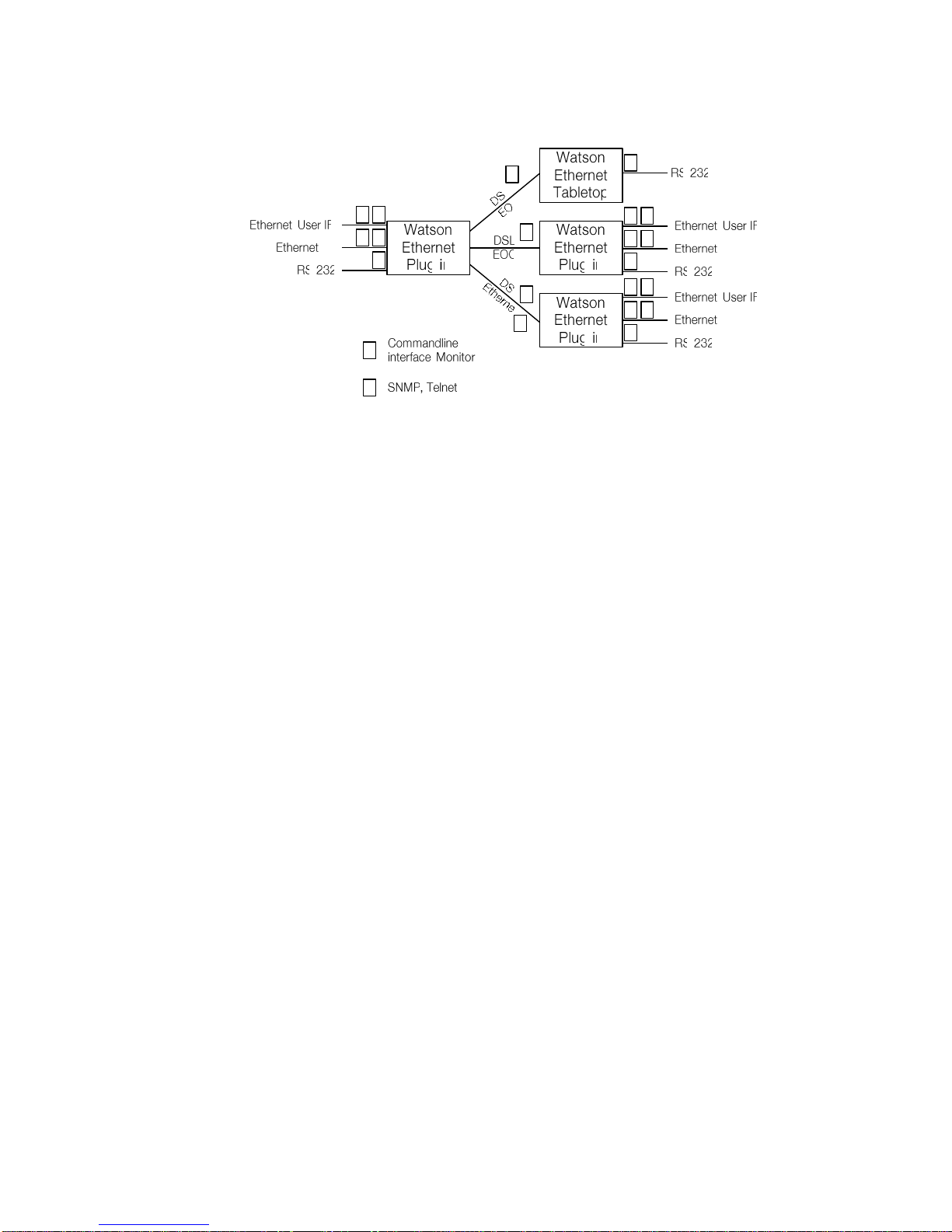
Watson Ethernet
Operating Manual
Watson-Ethernet-Manual.doc
Version 3.3-01
3-22
Revision: 2010-01-20
Figure 3-16: Management interfaces
Monitor access through the DSL EOC is only possible from a DSL master to a
DSL slave. DSL Master/Slave configuration and the Autorestart option cannot be
changed through the DSL EOC as doing so might result in loss of the communication between master and slave.
Telnet access gives the same commands as Monitor access through the local
RS-232 port. However it is not possible to modify IP parameters through Telnet
because doing so might result in loss of communication to the modem.
Page 45
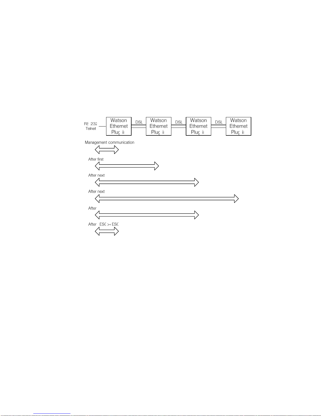
Watson-Ethernet-Manual.doc
Version 3.3-01
Watson Ethernet
Operating Manual
Revision: 2010-01-20
3-23
3.5.2 Chain Management through the DSL EOC
If several Watson Ethernet plug-ins are connected in a linear network then the
entire can be managed through the DSL EOC using the Monitor commands
CONNECT and DISCONNECT. CONNECT connects to the modem on a particular
DSL span. A next CONNECT will connect to the next modem in the chain.
DISCONNECT disconnects one segment in the chain. To connect an entire chain
at once you can use the combination <ESC><ESC> (the ESCAPE key pressed
twice).
CONNECT
CONNECT
DISCONNECT
CONNECT
Figure 3-17: Chain Management through the DSL EOC
It is also possible (and recommended) to use Ethernet inband management over
the DSL to manage a modem chain:
SNMP is only possible with Ethernet inband management
the EOC has a limited bandwidth and CLI reaction times will be slow, espe-
cially on long chains
However chain management through the EOC must be used sometimes, e.g. to
set up IP configurations in the remote modems.
Page 46
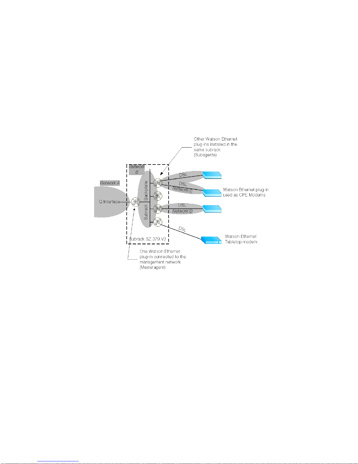
Watson Ethernet
Operating Manual
Watson-Ethernet-Manual.doc
Version 3.3-01
3-24
Revision: 2010-01-20
3.5.3 Management IP Address Configuration
Each Watson Ethernet plug-in contains a management router that connects
three networks:
one network at the Q – Interface (MGMT1) on the front panel of the modem
one network at the backplane interface (MGMT2) on the subrack
SZ.379.V3W
one network at the internal interface (MGMT3) connecting to the Ethernet
bridge
Cf. the block diagram of the Watson Ethernet plug-in Figure 3-4.
Figure 3-18: IP networks for Management
In a Watson Ethernet system where several plug-in cards are installed in a subrack and where the DSL spans are also terminated with Watson Ethernet plug-in
cards the following subnetworks must be configured:
one subnetwork (Network A) for the Q – Interface on the front panel of the
modem which is connected to the management system
one subnetwork (Network B) for the subrack connecting all backplane inter-
faces
one subnetwork for all DSL spans of a plug-in. Within a subrack the DSL
spans of each plug-in must be in separate subnetworks (Networks C, D in
Figure 3-18)
The Watson Ethernet tabletop modem does not have management routing functions. No subnetwork has to be defined for DSL spans that are terminated with
the tabletop modem.
Page 47
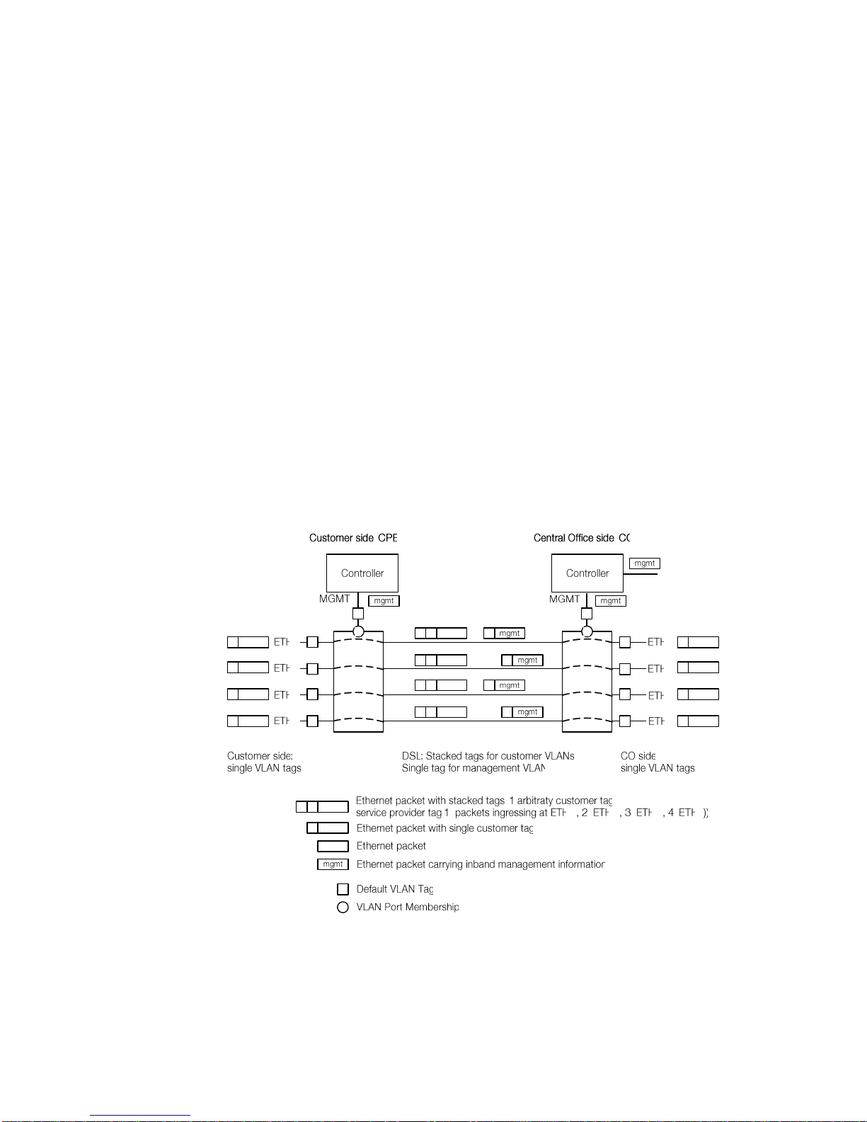
Watson-Ethernet-Manual.doc
Version 3.3-01
Watson Ethernet
Operating Manual
Revision: 2010-01-20
3-25
3.5.4 Management VLAN configuration
The Watson Ethernet plug-in modems support Ethernet inband management, i.e.
it is possible to manage the modems through the Ethernet user interfaces or
through the Ethernet payload carried over the DSL.
Ethernet inband management traffic is always routed through the internal management port MGMT3 that connects the plug-in controller to the Ethernet bridge.
To configure Ethernet inband management and to isolate management traffic
from user traffic a dedicated management VLAN has to be set up. By default the
MGMT3 port is member of VLAN 4094, but it is possible to use a VID different
from 4094 for management traffic.
To access MGMT3 from a user interface this user interface (ETH1 .. ETH4) has
to be member of the management VLAN. To access MGMT3 through the DSL
Ethernet payload the corresponding DSL span (DSL1 .. DSL4) has to be member
of the management VLAN.
3.5.5 Transparent bridging with inband management
The Watson Ethernet plug-in supports a special bridging mode that allows for inband management in combination with transparent bridging. This bridging mode
uses stacked VLAN tags for packets from the Ethernet user interfaces and single-tagged packets for management information on the DSL interfaces:
Figure 3-19: Transparent bridging with inband management
Management packets ingressing at the Q – interface of the Central Office are
routed to port MGMT3 of the management controller. There they are tagged with
the default VLAN tag m and are sent as single-tagged packets over the DSL to
the Watson Ethernet plug-in at the Customer side.
Page 48
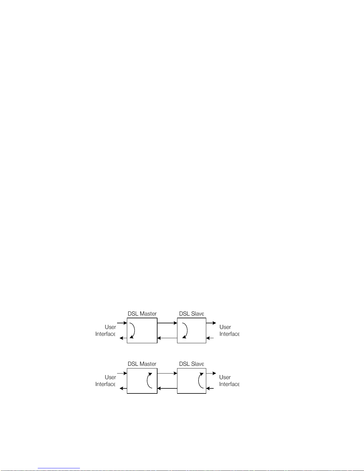
Watson Ethernet
Operating Manual
Watson-Ethernet-Manual.doc
Version 3.3-01
3-26
Revision: 2010-01-20
At the Customer side the outer tag is stripped off, leaving management packets
untagged. VLAN switching will send these packets to port MGMT3 which is
member of VLAN m.
Single-tagged packets ingressing at ports ETH1 .. ETH4 of the CPE modem will
be tagged with an outer tag s1 .. s4 depending on their ingress port and then
sent over the DSL. At the CO side the outer tag is stripped off, leaving singletagged packets egressing the CO modem at ETH1 .. ETH4.
Transparent bridging with inband management is configured with the Monitor
command BRIDGEMODE 3. This bridging mode must be enabled on both central
office (CO) and customer (CPE) modems.
3.6 G.826 Performance Monitoring
Watson Ethernet modems support performance monitoring as specified in ITU-T
G.826. The G.826 error performance parameters provide quantitative performance information of a specific loop. They are intended to be used for long-term
evaluation of operating DSL spans.
The evaluation of the G.826 error performance parameters is based on CRC
(Cyclic Redundancy Check) error detection. The estimation of a bit-error rate is
not within the scope of the G.826 calculations.
On the DSL side, six CRC6 check bits are generated per DSL frame for each
channel and direction. The software counts block errors and evaluates the error
performance according to ITU-T G.826 using these CRC6 bits.
G.826 statistics are available with the G826 Monitor command.
3.7 Test loops
Test loops can be activated via the Monitor or SNMP. Loop 1 will initiate a loopback on a local Ethernet interface, Loop 2 will initiate a loopback on a remote
DSL interface. Only one test loop can be active at a given time.
Activation of a test loop will deactivate any previous loop. A system reset will
deactivate any test loop. A non-urgent alarm is raised while any loop is active.
LOOP2LOOP1
Figure 3-20: Test Loops controlled by the DSL Master
LOOP2 LOOP1
Figure 3-21: Test Loops controlled by the DSL Slave
Page 49

Watson-Ethernet-Manual.doc
Version 3.3-01
Watson Ethernet
Operating Manual
Revision: 2010-01-20
3-27
Notes:
The looped-back Ethernet packets egress the modems from the same port
they were sent to and have the same source and destination addresses they
were sent with. While Ethernet testing equipment can handle this situation it
might be very confusing for normal Ethernet ports or Ethernet bridges.
The Watson Ethernet tabletop modems operated as DSL slave can only
control LOOP1.
3.8 Password protection
The Watson Ethernet modems feature password protection to management
functions to prevent unauthorized access e.g. on a modem that is installed at a
customer site but is owned and managed by the service provider.
Password protection is global i.e. once the correct password is entered access to
all commands is granted.
By default password protection is disabled. To enable it use the SET PASSWORD
command to define a password and then use the LOGOFF command to lock
access to the Monitor. Now Monitor access must be enabled by entering the
password before any Monitor commands can be entered.
Once the password is entered all Monitor commands are available. The password has to be re-entered
after each LOGOFF
after 5 minutes of inactivity
after a restart of the modem
Passwords can be changed with the CHANGE PASSWORD command. To disable
password protection use the CLEAR PASSWORD command.
Password protection is only applied to access from the local RS-232 interface.
Monitor access through the DSL EOC is never protected by the password. If a
password has been lost then it can be reset through the DSL EOC with the
CLEAR PASSWORD and SET PASSWORD commands.
Of course this is only possible if the modem who's password has been lost is
configured as DSL slave. If it is configured as DSL master then no remote
access through the DSL EOC is possible. In this situation the modem can be
configured as DSL slave with the DSLSLAVE command which can be entered at
the prompt for the password. After DSLSLAVE the modem will be reconfigured as
DSL slave and the password can be reset from the DSL master as described
above.
Page 50

Page 51

Revision: 2010-01-20
4-1
4 Powering
4.1 Plug-in
Each plug-in is fed via the subrack backplane with dual -48VDC (referenced to
0VDC of the exchange battery). The plug-in generates the used voltages onboard.
Additionally, the plug-in is fed over the backplane with an auxiliary +5VDC supply
(referenced to ground) generated on the ACU. The only purpose of this voltage
is to drive the alarm circuitry on each plug-in, even in the case of a failure of the
plug-in onboard powering circuitry
4.2 Tabletop
The tabletop modem is normally powered locally from an AC/DC adapter with
48VDC output. Power adapter SZ.410.080.V1E is available from Schmid Telecom to power the tabletop modem.
Caution:
Only power sources below maximum hazardous energy levels according IEC
60950-1 chapter 1.2.8.10 may be used as local power source. The insulation
voltage of the power source must support elevated insulation voltage according
to EN 60950-1 (at least 4 KV insulation). The power adapters available from
Schmid Telecom fulfill these requirements.
Caution:
Do not connect a 48VDC supply directly to the “AC/DC adapter” connector. High
voltage transients from the DSL line may damage the modem or other equipment
connected to the battery. A DC/DC converter with 4kV transient isolation voltage
must be used in this case.
Caution:
The local supply voltage input is protected against reversal of polarity but not
fused. Appropriate fusing has to be done externally.
The tabletop modem can also be powered through the DSL span from to a Watson TDM plug-in modem with remote powering functions. Switching between local and remote powering is done automatically with local power taking precedence over remote power feeding.
Note:
The Watson Ethernet plug-in does not support remote powering of a tabletop.
The ground of the tabletop modem is normally floating when referenced to earth.
A ground connector (Faston type) is available on the rear panel of the modem.
Page 52

Page 53

Revision: 2010-01-20
5-1
5 LEDs and Alarms
5.1 Plug-in LEDs
The plug-in is equipped with four LEDs. Depending on the currently selected
CARDMODE the LEDs are mapped to local and remote status as follows:
Cardmode
1 (4 x 1p)
2 (2 x 2p)
3 (1 x 2 + 2x1p)
4 (1 x 4p)
LED
Span
Function
Span
Function
Span
Function
Span
Function
A
DSL1
Local Status
DSL1
Local Status
DSL1
Local Status
DSL1
Local Status
B
DSL 2
Local Status
DSL1
Remote
Status
DSL1
Remote
Status
DSL1
Remote
Status
C
DSL 3
Local Status
DSL3
Local Status
DSL3
Local Status
-
Off D DSL 4
Local Status
DSL3
Remote
Status
DSL4
Local Status
-
Off
Table 5-1: LED mapping for plug-in
The "Local Status" LED indicates the status of the local end of the DSL span
(STU-C side). The Remote Status" LED indicates the status of the remote end of
the DSL span (STU-R side). If the modem is configured as DSL slave then only
the local status is indicated, the "Remote Status" LED is switched off.
5.1.1 Plug-in LED Indications
Status
LED
Power failure
Off
Hardware / Software failure
blinking red
Normal operation (Master)
Green
Normal operation (Slave)
Green
Non-urgent alarms (local/remote) or loop active
Amber
Urgent alarms (local/remote)
Red
Table 5-2: Plug-in LED indications
Page 54

Watson Ethernet
Operating Manual
Watson-Ethernet-Manual.doc
Version 3.3-01
5-2
Revision: 2010-01-20
5.2 Tabletop LEDs
5.2.1 Front LEDs
The tabletops are fitted with two LEDs labeled "1" and "2" ("Local" and "Remote"
on some older modems, "1" is equivalent to "Local" and "2" to "Remote"). The
LEDs display the local status and (if the tabletop is configured as a DSL master)
the remote status:
Status
LED "1"
LED "2"
Power failure
Off
Off
Hardware / Software failure
Blinking red
Off
Memory Selftest Failure (Watson
Ethernet tabletop only)
Off
Red
Normal operation (Master)
Green
Green
Normal operation (Slave)
Green
Off
User Interface Activity on Tx (Slave)
Green
Blinking Green
User Interface Activity on Rx (Slave)
Green
Blinking Amber
Non-urgent alarms (local/remote) or
loop active
Amber
Amber (off for Slave)
Urgent alarms (local/remote)
Red
Red (off for Slave)
Table 5-3: Tabletop front LED indications
During Firmware download the LEDs are used as follows:
Download Status
LED "Local"
LED "Remote"
Flash erase
blinking red
Off
Download in progress
blinking green
Off
Download completed
blinking amber
Off
Activating remotely downloaded firmware
Off
blinking amber
Table 5-4: Tabletop front LED indications during firmware download
Page 55

Watson-Ethernet-Manual.doc
Version 3.3-01
Watson Ethernet
Operating Manual
Revision: 2010-01-20
5-3
5.2.2 Back LEDs
The Watson Ethernet tabletop modem is fitted with 2 LEDs on the backpanel indicating the status of the Ethernet interface: (Activity ACT and High-Speed HS
indicator):
Status LED
ACT (Green)
HS (Amber)
Link down
Off
Off
Link up, 10 Mbps, no activity
On
Off
Link up, 100 Mbps, no activity
On
On
Link up, 10 Mbps, activity
Blinking
Off
Link up, 100 Mbps, activity
Blinking
On
Table 5-5: Tabletop backpanel Ethernet LED indications
5.3 Alarm Conditions
An alarm condition is displayed on the LEDs if one of the following conditions occurs:
Urgent alarm (red):
Hardware or software failure (blinking)
Loss of signal / frame alignment on the DSL side (LOSW)
DSL block-error-rate according G.826 30% (BER-H)
Plug-in only: overcurrent detected in remote power feeding circuit (CLD)
Non-urgent alarm (amber):
DSL block-error-rate according G.826 > 15% (BER-L)
Either Loop 1, Loop 2, Analog Loopback, or the Regenerator Loopback is ac-
tive (LOOP1, LOOP2, BERT)
Link integrity alarm on Ethernet user interface
Alarm cut off is activated (ACO)
5.4 Alarm Relays
5.4.1 Plug-in
Plug-in alarms can be signaled through relay contacts present on the ACU2R
which is normally installed in the subrack. Two relays are present on the ACU2R
for urgent and non-urgent alarms.
Note:
The ACU-48R is not compatible with the Watson Ethernet plug-in.
Under normal plug-in power conditions the two output stages of each plug-in are
controlled by its microcontroller. In case of a power failure on an plug-in, both the
“Urgent” and “Non-urgent” alarms will be activated on the ACU. (The ACU gene-
Page 56

Watson Ethernet
Operating Manual
Watson-Ethernet-Manual.doc
Version 3.3-01
5-4
Revision: 2010-01-20
rates an auxiliary +5 VDC which is used to pull-up the open collector alarm output
stages of the plug-ins.)
Both minirack mechanics and the plug-in tabletop housing have urgent and nonurgent alarm relay contacts.
Urgent Alarm:
At least one of the plug-in – LEDs displays an urgent alarm
Power failure of any one of the plug-ins
Power failure of the auxiliary +5VDC auxiliary supply on the ACU
Power failure of both –48VDC supplies
Non-urgent Alarm:
At least one of the plug-in – LEDs displays a non-urgent alarm and none of
the plug-in – LEDs displays an urgent alarm
Power failure of any one of the plug-ins
Power failure of the auxiliary +5VDC auxiliary supply on the ACU
Power failure of one of the –48 VDC supplies
5.5 Initialization Errors
At system startup, various hardware selftests are performed. If any initialization
errors occur, the startup procedure will be aborted and appropriate error messages are sent to the serial interface (RS-232).
On the Watson Ethernet tabletop an initialization error code in hexadecimal representation is sent to the serial interface:
Error Code
Initialization Error
0x0001
Microcontroller RAM test failure
0x0002
EEPROM test failure
0x0004
Framer initialization failure
0x0008
DSL transceiver failure (Loop A)
0x0010
DSL transceiver failure (Loop B)
0x0080
Ethernet interface initialization failure
0x8000
Software Copyright Protection Error
Table 5-6: Software Initialization Errors (tabletop modem).
If several errors are detected simultaneously then the error code displayed is a
combination (OR) of the individual error codes, e.g. 0x83 will be displayed if during selftest the RAM test fails, the EEPROM test fails and the Ethernet interface
cannot be initialized.
Page 57

Revision: 2010-01-20
6-1
6 The Monitor
6.1 Introduction
For configuration and diagnostics the modems have a serial interface to connect
a terminal or a PC with terminal emulation. The serial interface is available on the
backplane of the tabletops, on the ACU, the minirack mechanics and the plug-in
tabletop housing.
A modem configured as DSL slave is also accessible from the master side
through the DSL EOC.
The Monitor terminal or terminal emulation must be VT100 compatible and must
be configured as follows:
9600 baud, asynchronous
8 bits, no parity, one stop bit
No new line on carriage return (i.e. no line feed on carriage return)
XON/XOFF enabled
Notes:
Between plug-in and the terminal the XON/XOFF protocol is used for flow
control. In order to re-enable communication with an plug-in occasionally left
in XOFF state, it is recommended to start each session with Ctrl-Q (=XON)
followed by an ECHO command.
If you use the HyperTerm terminal emulator delivered with Windows® then
you must configure HyperTerm for VT100 emulation in the "Settings" tab of
the connection properties (File – Properties).
Page 58

Watson Ethernet
Operating Manual
Watson-Ethernet-Manual.doc
Version 3.3-01
6-2
Revision: 2010-01-20
6.2 Addressing of Plug-ins
6.2.1 Plug-in in Subrack
The Monitor terminal connects through the ACU to a serial bus on the subrack
backplane which is accessible by all plug-ins.
At any time, only one of the plug-ins in the subrack can be logically connected to
the Monitor interface. The appropriate plug-in interface is addressed (i.e. selected) according to its physical position in the subrack, starting with the leftmost
slot number 01 and ascending rightwards to number 12. To select a plug-in in
slot number nn just type %nn in the terminal, e.g. to select the plug-in in slot 7
type %07.
%01 %02 %03 %04 %05 %06 %07 %08 %09 %10 %11 %12
Figure 6-1: Plug-in Addressing Scheme
To see which units in a rack are available, you can use the ECHO command.
Each unit will respond with its associated slot number (%SN).
The response could be: %01 %03 %08 %10 %11
Notes:
The ECHO command is not echoed on the terminal
The selection command (%nn) is not echoed on the terminal
Each command must be terminated by a carriage return.
6.2.2 Plug-in in Minirack mechanics or tabletop housing
No addressing procedure is required in these cases. After power-up the Monitor
menu appears directly.
6.2.3 Tabletop
There is no addressing procedure required for Tabletop modems. After power-up
of a Tabletop modem the Monitor menu appears.
Page 59

Watson-Ethernet-Manual.doc
Version 3.3-01
Watson Ethernet
Operating Manual
Revision: 2010-01-20
6-3
6.3 Naming of ports
Many commands of the Monitor relate to a particular port. These ports are identified as follows:
Port
Name
Bridge port of 1st DSL span
DSL1
Bridge port of 2nd DSL span
DSL2
Bridge port of 3rd DSL span
DSL3
Bridge port of 4th DSL span
DSL4
1st Ethernet user interface
ETH1
2nd Ethernet user interface
ETH2
3rd Ethernet user interface
ETH3
4th Ethernet user interface
ETH4
1st Management Ethernet interface (Q)
MGMT1
2nd Management Interface (Backplane)
MGMT2
3rd Management Interface (Bridge)
MGMT3
Table 6-1: Port naming
Cf. also Figure 3-4.
The number of DSL spans varies depending on the card configuration set by the
CARDMODE command, cf. Table 3-1.
6.4 Telnet Access
To use a remote Monitor through Telnet on the Watson Ethernet plug-in you first
have to configure the IP address of the plug-in through a monitor on the RS-232
interface with the MGMTIP command.
Then use any Telnet client to open a telnet session into the modem. You will see
a Telnet welcome screen:
+-----------------------------------------------+
| Welcome to Watson Ethernet Quad LTU |
| (C) by Schmid Telecom AG Zuerich, Switzerland |
+-----------------------------------------------+
OS/HW: Linux ppc 2.4.20
Nodename: SzW5EthLtu
SzW5EthLtu login:
Enter username and password to display the Monitor Welcome Screen.
Note:
The default username is root, the default password is sz . It is not possible to
change these.
Page 60

Watson Ethernet
Operating Manual
Watson-Ethernet-Manual.doc
Version 3.3-01
6-4
Revision: 2010-01-20
6.5 Monitor Command Structure
6.5.1 Welcome Screen
After connecting the Terminal/PC the welcome screen is shown with information
about the modem type and Firmware Version, e.g.:
Watson 5 SHDSL Ethernet
ZRH01
Monitor V3.0
Copyright (C) 2001-2006 by Schmid Telecom AG Zuerich, Switzerland
+-----------------------+
| Main Menu |
+-----------------------+
1. Performance management (PM)
2. Fault and maintenance management (FMM)
3. Configuration management (CM)
4. Security and remote management (SM)
5. Exit
LTU_01>
To select the desired sub-menu, type the appropriate number.
The available Monitor commands are described in chapter 7.
Notes:
The Exit command is only available on the plug-in if it is installed in a sub-
rack or accessed via Telnet..
To address another plug-in in the subrack after Exit type %nn (nn = slot
number)
6.5.2 Menus
The Monitor menu is structured in the following sub-sets:
Subset
Short-form
Performance management
PM
Fault and maintenance management
FMM
Configuration management
CM
Security and remote management
SM
Table 6-2: Monitor Command Subsets
Page 61

Watson-Ethernet-Manual.doc
Version 3.3-01
Watson Ethernet
Operating Manual
Revision: 2010-01-20
6-5
6.5.3 Prefixes an Shortcuts
The available commands depend on the submenu currently active.
To access a command from a different submenu the command can be prefixed
with the name of the submenu and a . (Dot), e.g. you can use PM.G826 DSL1
to display the G.826 statistics for SHDSL span 1 while in the Configuration submenu. If the Performance Management submenu is active then G826 DSL1 will
display the G.826 statistics and CM.CONFIG DSL1 will display the configuration
of DSL span 1.
Note:
Prefixing is only available on the Watson Ethernet plug-in.
The most popular commands are available in all submenus as shortcuts:
Command
Shortcut
CONNECT
CON
DIAGNOSTIC
DIA
DISCONNECT
DIS or <ESC>
key
Table 6-3: Command Shortcuts
6.5.4 Tab completion
You can use tab completion to simplify typing of long commands. By typing the
<TAB> character in after entering the first character(s) of a command word the
Monitor will try to complete the command as much as possible. Example:
LTU_01_CM> SN <TAB> will do a partial completion of the command to
LTU_01_CM> SNMP
Typing now C <TAB> will complete the command to
LTU_01_CM> SNMPCOMMUNITY
Notes:
Tab completion is only possible for commands, not for parameters.
Tab completion is only available on the Watson Ethernet plug-in.
6.5.5 Help
Typing H or HELP at any submenu will list all commands available in that submenu in alphabetical order. Typing H Command (or HELP Command) will display
help for a particular command.
6.5.6 Command History
The Watson Ethernet plug-in keeps a command history. To recall a command
recently entered use the up-arrow and down-arrow keys to scroll through the history of commands. Commands may be edited by using the DEL key and the cursor keys.
Page 62

Watson Ethernet
Operating Manual
Watson-Ethernet-Manual.doc
Version 3.3-01
6-6
Revision: 2010-01-20
6.5.7 Continuous Displays
Some commands (DIAGNOSTIC, G.826, BERT) continuously update the screen
with the latest information. These commands will stop updating the screen if a
new command is entered that generates displays with more than one line. (e.g.
CONFIG, STATUS, ALARM, READBER).
Page 63

Revision: 2010-01-20
7-1
7 Monitor Command Reference
7.1 Introduction
This chapter defines the Monitor command language. The language is made up
of the following elements:
COMMAND
Commands are written in CAPITALS
KEYWORD
Keywords are written in CAPITALS
Parameter
Parameters are written in Italics. Replace the
parameter with the actual value. Example:
LINERATE n
Parameter | Parameter
KEYWORD | KEYWORD
Choices are denoted with vertical bars |. In a
choice group one of the parameters must be
specified.
[ Parameter ]
[ KEYWORD ]
Optional parameters are enclosed in [ brackets ]. Optional parameters can be specified
but are not required.
{ Parameter-List }
A parameter list is enclosed in { braces }. A
list of parameters is a sequence of parameters separated by one or more spaces.
Table 7-1: Command language elements
Page 64

Watson Ethernet
Operating Manual
Watson-Ethernet-Manual.doc
Version 3.3-01
7-2
Revision: 2010-01-20
7.2 Configuration Management CM
7.2.1 General Commands
ADMIN-NAME [ SYSTEM String | DSLx String ]
Defines an administrative name for the system or for one of the DSL spans.
The administrative name of the system is displayed in the Monitor welcome
screen, the administrative names of the DSL spans in the STATUS display. Use
quotes (" ") to enter upper/lowercase administrative names.
The command ADMIN-NAME without parameters will display all currently configured administrative names.
Note
This command is not available on the Watson Ethernet tabletop modem.
ADMINSTATUS Port UP | DOWN
Set the administrative state of a port.
Parameters:
Port
Port (DSL1 .. DSL4, ETH1 .. ETH4)
UP, DOWN
Administratively enable (UP) or disable (DOWN) the
port.
Ports that are set to DOWN are blocked for traffic and do not create any alarms.
The currently active administrative status is displayed in the STATUS and
STATUS ETHERNET commands.
Notes
Setting the ADMINSTATUS of a DSL span to DOWN deactivates the DSL physi-
cal layer. Three alarms (SNMP Traps) are generated in this situation: Link
Down alarm, SNR margin alarm and Loop attenuation alarm
Setting the ADMINSTATUS of an Ethernet port to DOWN deactivates the Ether-
net physical layer. Other devices connected to this port will generate a link integrity alarm.
This command is not available on the Watson Ethernet tabletop modem.
Page 65

Watson-Ethernet-Manual.doc
Version 3.3-01
Watson Ethernet
Operating Manual
Revision: 2010-01-20
7-3
CARDMODE [ mode ]
The Watson Ethernet plug-in can be configured flexibly to support 1/2/4 pair operation. This is done with the CARDMODE command. Entering CARDMODE without
any parameter will display the current plug-in mode:
LTU_01_CM> CARDMODE
Current cardmode: 4x1 pair (mode 1)
Bridge Port Wire Pair
~~~~~~~~~~~~~~~~~~~~~~~~~~~~~~~~~~~~~~~
DSL1 <-------------> a1a2
DSL2 <-------------> b1b2
DSL3 <-------------> c1c2
DSL4 <-------------> d1d2
Available CARDMODEs:
1
4x1p, four independent 1-pair systems
2
2x2p, two independent 1-pair systems
3
1x2p + 2x1p, one 2-pair and two 1-pair systems
4
1x4p, one 4-pair system
When changing the cardmode, the newly configured DSL spans will be reset and
their configuration set to the default configuration of the new mode as defined in
Table 7-2. Note that only the DSL defaults are set, the Ethernet interface configuration is not changed by CARDMODE. For security reasons, the command must
be confirmed.
The Watson Ethernet tabletops have no card mode.
Page 66

Watson Ethernet
Operating Manual
Watson-Ethernet-Manual.doc
Version 3.3-01
7-4
Revision: 2010-01-20
DEFAULT Configuration
The DEFAULT command sets a default configuration. The following default settings are available on the plug-in:
Parameter
DEFAULT 0
DEFAULT 1
DEFAULT 2
SHDSL
Master/Slave
Master
Master
Master
Autorestart
Enabled
Enabled
Enabled
Power
Backoff
Enabled
Enabled
Enabled
Linerate per
span
8'192 kbit/s
4'096 kbit/s
2'048 kbit/s
Operating
Mode
1 x 4 Pair
2 x 2 Pair
4 x 1 Pair
DSL Sync
rate per pair
2'056 kbit/s
2'056 kbit/s
2'056 kbit/s
Ethernet
Interface
mode
Auto
Auto
Auto
Flow control
Auto
Auto
Auto
VLAN Settings
Bridgemode
1 (VLAN Bridging)
VLANs
VLAN 1: ETH1,
DSL1
VLAN 1: ETH1,
DSL1
VLAN 3: ETH3,
DSL3
VLAN 1: ETH1, DSL1
VLAN 2: ETH2, DSL2
VLAN 3: ETH3, DSL3
VLAN 4: ETH4, DSL4
VLAN 4094: MGMT3
All ports are configured as untagged
CoS Settings
Default
Priority
Q1 on all ports
Priority
source
IEEETHENIP on all ports
Priority mapping
L2 Priority: 0 1 2 3 4 5 6 7
Queue : Q2 Q1 Q1 Q2 Q3 Q3 Q4 Q4
Table 7-2: DEFAULT values (plug-in)
Page 67

Watson-Ethernet-Manual.doc
Version 3.3-01
Watson Ethernet
Operating Manual
Revision: 2010-01-20
7-5
For the Watson Ethernet tabletop modems the DEFAULT values are as follows:
Parameter
DEFAULT 0
DEFAULT 1
DEFAULT 2
SHDSL
Autorestart
Enabled
Enabled
Enabled
Power Backoff
Disabled
Disabled
Disabled
Payload Rate
2048 kbit/s
2304 kbit/s
4608 kbit/s
Operating Mode
1 Pair
1 Pair
2 Pairs
Line Rate
2056 kbit/s
2312 kbit/s
2312 kbit/s
Ethernet
Bit Rate
2048 kbit/s
2304 kbit/s
4608 kbit/s
FDX
Auto
Auto
Auto
Flow
Auto
Auto
Auto
Filtering
On
On
On
Aging Time
300s
Remote
Remote
Scheduling
Strict
Strict
Strict
Ratelimit
Off
Off
Off
Table 7-3: DEFAULT values (tabletop)
Notes
The default configurations are given for DSL master mode. If the modem is in
DSL slave mode then the DSL linerate is determined by the DSL master and
not by the DEFAULT command.
The factory setting can be loaded using the DEFAULT 2 command. All DSL
plug-ins and tabletops are delivered with this configuration (plug-ins as DSL
master, tabletops as DSL slave).
The Master/Slave and Remote Powering settings are not affected by the
DEFAULT command
Page 68

Watson Ethernet
Operating Manual
Watson-Ethernet-Manual.doc
Version 3.3-01
7-6
Revision: 2010-01-20
7.2.2 DSL Configuration (Plug-in)
BACKOFF Span ON | OFF
Set SHDSL Power Back-Off function ON / OFF for a particular DSL span. The
default setting is BACKOFF ON.
CONFIG DSL Span
The CONFIG command displays the current configuration of a DSL spans of the
unit. You can also use CONFIG Span as a shortcut.
LTU_01_CM> CONFIG DSL1
~~~~~~~~~~~~~~~~~~~~~~~~~~~~~~~~~~~~~~~~~~
Local Configuration of SHDSL Span No 1
~~~~~~~~~~~~~~~~~~~~~~~~~~~~~~~~~~~~~~~~~~
Master/Slave : Master
Autorestart : Enabled
Power Backoff : Enabled
Payload Rate (max): 2048 kbit/s
Wire Pairs : 1
Line Rate : 2056 kbit/s
Line Code : PAM-16
FALLBACK Span [ timeout | OFF ]
Activates or deactivates single-pair fallback for a DSL span. The timeout value
specifies the number of minutes the STU-C tries to restart a multipair span before reverting to single-pair fallback. It is recommended to use 3 minutes as
timeout value.
FALLBACK Span will display the current configuration of single-pair fallback of a
span.
Note
It is not required to configure FALLBACK mode on the STU-R side. The entire fallback process is controlled by the STU-C
LINERATE Span n p
Set line rate for a DSL span
Parameters:
Span the DSL span
n number of DSL timeslots to be transmitted (3 n 89)
p number of constellations used: p = 16 for TC-PAM 16, p = 32 for TC-
PAM 32. If possible (i.e. consistent with n) the DSL span will be configured accordingly. If p is omitted then PAM-16 will be configured when
possible and PAM-32 otherwise.
MASTER Span ON | OFF
Set DSL master mode ON/OFF for a DSL span. On the Watson Ethernet plug-in
each DSL span can be configured individually as master or slave.
Page 69

Watson-Ethernet-Manual.doc
Version 3.3-01
Watson Ethernet
Operating Manual
Revision: 2010-01-20
7-7
RESTART Span ON | OFF
Set Autorestart ON / OFF for a DSL span
7.2.3 DSL Configuration (Tabletop)
There is only one DSL interface available on the tabletop modem. The DSL configuration commands are somewhat simplified.
BACKOFF ON | OFF
Set SHDSL Power Back-Off function ON / OFF.
CONFIG
Shows the current configuration (DSL and Ethernet ports)
NTU_CM_REMOTE> CONFIG
~~~~~~~~~~~~~~~~~~~~~~~~~~~~~~~~~~~~~~~~~~~~~~~~~~~~~~~~~~~~~~~~~~
Local Configuration Id : Ethernet
~~~~~~~~~~~~~~~~~~~~~~~~~~~~~~~~~~~~~~~~~~~~~~~~~~~~~~~~~~~~~~~~~~
ETH
Bit Rate : 32 x 64 = 02048 kbit/s
FDX : Auto
Flow : Auto
Filtering : On
Aging Time : 300s
Scheduling : WFQ
Provider Tag : ETH: Off DSL: Off
TPID : ETH: 0x88A8 DSL: 0x88A8
Prio Source : ETH: IPTHENIEEE DSL: IPTHENIEEE
Default VLAN : ETH: 0x001 DSL: 0x001
Default Prio : ETH: 7 DSL: 7
Ratelimit : Off
SHDSL
Master/Slave : Slave
Autorestart : Enabled
Power Backoff : Disabled
Payload Rate : 02048 kbit/s
Operating Mode : 2 Pair, plesiochronous
Line Rate : 01032 kbit/s
Wetting Current : Off
Management
Admin Name : (void)
LINERATE n i
Set line rate:
Parameters:
n denotes the number of DSL timeslots to be transmitted (3 n 89)
i 1 denotes the Z-bits automatically used to increase the EOC bandwidth
of about 3.2 kbit/s by 8 kbit/s (i = 0 or 1, default i =1 )
Notes
The LINERATE command is only available if the modem is acting as a DSL
master (MASTER ON). If the modem is configured as DSL slave then the linerate is set by the master.
Use of Z-bits for the EOC and asymmetric PSD operation is provided for com-
patibility of the Watson Ethernet tabletop with Watson TDM modems, cf. [8].
The Watson Ethernet plug-in does not support these features.
Page 70

Watson Ethernet
Operating Manual
Watson-Ethernet-Manual.doc
Version 3.3-01
7-8
Revision: 2010-01-20
MASTER ON | OFF
Set DSL master mode ON/OFF.
MODE 1 | 2
Select DSL operating mode:
1: 1 pair operation
2: 2 pair operation
RESTART ON | OFF
Set Autorestart ON / OFF.
WETTING ON | OFF
Set wetting current sink ON / OFF.
7.2.4 Ethernet Configuration (Plug-in)
FDX Ethernet-Port mode
Sets duplex mode and speed of an Ethernet port (ETH1 .. ETH4).
Possible values for mode:
AUTO Autonegotiation of parameters
10H 10 MBit/s, half duplex
10F 10 MBit/s, full duplex
100H 100 MBit/s, half duplex
100F 100 MBit/s, full duplex
FLOW Ethernet-Port AUTO | ON | OFF
Ethernet flow control:
AUTO Auto negotiation
ON flow control enabled
OFF flow control disabled
Flow control is implemented with PAUSE frames in full duplex mode and with
backpressure (forced collisions) in half duplex mode.
Note
It is not possible to auto-negotiate flow control without auto-negotiating speed and
duplex modes. Setting FDX to a value different from AUTO and then setting FLOW to
AUTO results in disabling flow control, i. e. has the same effect as FLOW OFF.
MDS Ethernet-Port {Ethernet-Port} [ ON | OFF ]
Enables/disables MAC Defect Signaling for an Ethernet user interface.
MDS Ethernet-Port will display the current state of MDS for a particular inter-
face.
MDS can be controlled for several interfaces with a single command, e.g.
Page 71

Watson-Ethernet-Manual.doc
Version 3.3-01
Watson Ethernet
Operating Manual
Revision: 2010-01-20
7-9
MDS ETH1 ETH2 ETH3 ETH4 ON
will enable MDS on all four Ethernet user interfaces.
7.2.5 Ethernet Configuration (Tabletop)
BITRATE n
Defines the bandwidth used on the DSL span for Ethernet data.
n number of 64 kbit/s timeslots (0 .. 178, FULL)
If the Watson Ethernet tabletop modem is connected to the Watson Ethernet
plug-in modem then the BITRATE must be exactly equal to the DSL LINERATE
in single pair operation or the BITRATE must equal 2 * LINERATE in two-pair
operation.
If the Watson Ethernet tabletop modem is used in a back-to-back configuration
(or connected to a Watson TDM modem with E1 or V35 interfaces) then the
BITRATE must be less or equal than the LINERATE (or 2 * LINERATE in 2-pair
operation).
When the bitrate configured with the BITRATE command exceeds the available
DSL linerate or the BITRATEs on both ends of the link to not match then an appropriate warning is displayed in the Monitor of the tabletop modem.
Cf. chapter 3.2
When BITRATE = FULL the Ethernet interface is automatically configured to fill
up the DSL payload with the maximum possible Ethernet packets. This mode is
very usefull when the Watson Ethernet tabletop modem is connected to the Watson Ethernet plug-in modem.
CONFIG
Displays the current configuration of DSL and Ethernet ports. Cf. 7.2.3.
FDX mode
Ethernet interface operating mode. Possible values for mode:
AUTO Auto negotiation (factory default)
10H 10 Mbps half duplex mode
10F 10 Mbps full duplex mode
100H 100 Mbps half duplex mode
100F 100 Mbps full duplex mode
FLOW AUTO | ON | OFF
Ethernet flow control:
AUTO Auto negotiation
ON flow control enabled
OFF flow control disabled
Flow control is implemented with PAUSE frames in full duplex mode and by
backpressure (forcing collisions) in half duplex mode.
Page 72

Watson Ethernet
Operating Manual
Watson-Ethernet-Manual.doc
Version 3.3-01
7-10
Revision: 2010-01-20
HDLCTAG ON | OFF
ON Ethernet frames are transmitted over the DSL span with Cisco HDLC fram-
ing
OFF Ethernet frames are transmitted with compressed HDLC framing. This set-
ting must be used if the Watson Ethernet tabletop is connected to the Watson Ethernet plug-in.
Cf. chapter 3.2
7.2.6 Ethernet Bridging Configuration (Plug-in)
AGING [ Time ]
Defines the aging time for all entries in the address learning database of the
Ethernet bridge.
Parameter:
Time
Aging time in seconds: 16 .. 4'000
AGING without parameters will display the current aging time.
BRIDGEMODE [ Mode ]
Sets the Ethernet bridge mode. Cf. 3.2.2
Parameter:
1
VLAN bridging: bridging is based on 802.1Q based VLAN tags
2
Transparent bridging (port-based)
3
Transparent bridging with inband management cf. 3.5.5
BRIDGEMODE without parameter will display the currently active Bridgemode.
CONFIG ETHERNET Ethernet-Port
Shows the current configuration of an Ethernet port:
LTU_01_CM> CONFIG ETHERNET ETH1
~~~~~~~~~~~~~~~~~~~~~~~~~~~~~~~~~~~~~~~~~~~~~~~~~~~~~~~~
Local Configuration of Bridges Ethernet Port ETH1
~~~~~~~~~~~~~~~~~~~~~~~~~~~~~~~~~~~~~~~~~~~~~~~~~~~~~~~~
AutoNegFDX : auto
FlowControl : off
Doubletagging : off
DefaultVlanId : 1
DefaultPrio : Q1
VlanList : egress tagged : egress untagged : 1
Loop : Off
PrioSrc : IEEETHENIP
FLT [ ON | OFF ]
Bridge filtering mode (global for the entire bridge):
ON MAC address filtering enabled. Only broadcast packets and packets with
destination addresses known to be on the Ethernet segment of a port will
be forwarded to this port. Address filtering is VLAN aware.
Page 73

Watson-Ethernet-Manual.doc
Version 3.3-01
Watson Ethernet
Operating Manual
Revision: 2010-01-20
7-11
OFF MAC address filtering disabled. All Ethernet packets are transferred trans-
parently to all Ethernet interfaces.
Typing FLT without argument displays the current configuration
7.2.7 Ethernet Bridging Configuration (Tabletop)
AGING [ Time ]
Defines the aging time for all entries in the address learning database of the
Ethernet bridge.
Parameter:
Time
Aging time in seconds: 0 .. 3825
AGING without parameters will display the current aging time.
FLT [ ON | OFF ]
Bridge filtering mode (global for the entire bridge):
ON MAC address filtering enabled. Only broadcast packets and packets with
destination addresses known to be on the Ethernet segment of a port will
be forwarded to this port. Address filtering is VLAN aware.
OFF MAC address filtering disabled. All Ethernet packets are transferred trans-
parently to all Ethernet interfaces.
Typing FLT without argument displays the current configuration
7.2.8 VLAN Configuration (Plug-in)
CONFIG VLAN
VLAN without parameters displays the current VLAN configuration:
LTU_01_CM> CONFIG VLAN
~~~~~~~~~~~~~~~~~~~~~~~~~~~~~~~~~~~~~~~~~~~~~~~~~~~~~~~~~~~~~~~~~~~~~~~~
VLAN-Id FID ETH DSL MGMT Name
1* 2* 3* 4* 1* 2* 3* 4* 3*
~~~~~~~~~~~~~~~~~~~~~~~~~~~~~~~~~~~~~~~~~~~~~~~~~~~~~~~~~~~~~~~~~~~~~~~~
1 1 U - - - T - - - - VLAN-1
2 2 - U - - - T - - - VLAN-2
3 3 - - U - - - T - - VLAN-3
4 4 - - - U - - - T - VLAN-4
4094 16 - - - - - - - - U VLAN-4094
~~~~~~~~~~~~~~~~~~~~~~~~~~~~~~~~~~~~~~~~~~~~~~~~~~~~~~~~~~~~~~~~~~~~~~~~
Ports: ETH1 ETH2 ETH3 ETH4 DSL1 DSL2 DSL3 DSL4 MGMT3
Default Vlan: 1 2 3 4 1 2 3 4 4094
Default Prio: Q1 Q1 Q1 Q1 Q1 Q1 Q1 Q1 Q4
Doubletagging: off off off off off off off off
Bridgemode: 2 (Transparent VLAN)
VLAN-ID
VLAN Id
FID
Forwarding database used for this VLAN
Page 74

Watson Ethernet
Operating Manual
Watson-Ethernet-Manual.doc
Version 3.3-01
7-12
Revision: 2010-01-20
ETH 1-4
DSL 1-4
MGMT3
- this port is not member of this VLAN
U this port is member of this VLAN, egress frames
will be sent without VLAN tag
T this port is member of this VLAN, egress frames
will be sent with VLAN tag
Ports marked with * do not use VLANs for switching,
but are configured for transparent bridging.
Name
Administrative name of this VLAN
Default VLAN
Default VLAN for this port
Default Prio
Default priority for this port
Doubletagging
Second VLAN tag will be added on egress
Bridgemode
Currently active Bridgemode
DEFAULTVLAN Bridge-Port VLAN-ID Priority
Sets the default VLAN ID and the default priority for untagged packets entering
the plug-in.
Bridge-Port
One of the bridge ports (ETH1 .. ETH4, DSL1 .. DSL4,
MGMT3)
VLAN-ID
VLAN ID to add to all untagged packets entering at this
port (1 .. 4094). Note that the Bridge-Port must also be
member of this VLAN – otherwise all untagged packets
will be discarded.
Priority
Default priority to assign to all untagged packets entering at this port. Four priority levels (Q4, Q3, Q2, Q1) are
supported. Q4 is the highest priority level.
If a VLAN tag is added to an Ethernet packet on egress
then the priority levels are mapped to IEEE 8021.1p bits
as follows:
Q4 110
Q3 100
Q2 010
Q1 000
DOUBLETAGGING Bridge-Port Direction
Enables/disables double tagging (stacked VLAN operation) on a bridge port, cf.
3.2.5.
Bridge-Port
One of the bridge ports (ETH1 .. ETH4, DSL1 .. DSL4)
Direction
OFF Double tagging is disabled
IN Double VLAN tags are expected on this
port. The first (outer) VLAN tag will be
removed before the packet is
Page 75

Watson-Ethernet-Manual.doc
Version 3.3-01
Watson Ethernet
Operating Manual
Revision: 2010-01-20
7-13
processed any further. If an incoming
packet has a single tag then this tag
will be removed. Untagged frames will
not be modified.
OUT An outer VLAN tag will be added to the
packet sent over this port. Untagged
packets will be sent tagged. Tagged
packets will be sent double-tagged.
The VLAN ID of the outer tag is defined
by the default VLAN ID of the source
port. The priority-bits of the extra tag
are determined by the default priority of
the ingress port. (DEFAULTVLAN
command).
InAndOut Combination of IN and OUT
VLANADD VLAN-ID { Bridge-Port T | U }
Adds a bridge port to a VLAN. A list of bridge-ports can be specified in a single
command:
VLAN-ID
VLAN Id (1 .. 4094)
Bridge-Port
ETH1 .. ETH4, DSL1 .. DSL4, MGMT3
T
U
T Ethernet frames will be sent from this port with
VLAN tags
U Ethernet frames will be sent from this port without
VLAN tags
Note
Never configure port MGMT3 with VLAN tags. The Watson Ethernet plug-in controller does not support tagged Ethernet packets..
VLANCREATE VLAN-ID FID Administrative-Name
Creates a new VLAN.
VLAN-ID
VLAN Id (1 .. 4094)
FID
Forwarding database to be used for this VLAN (1 .. 16).
AdministrativeName
An administrative name for this VLAN. Arbitrary text
string.
VLANDEL VLAN-ID { Bridge-Port }
Removes a bridge port from a VLAN. A list of bridge-ports can be specified in a
single command:
VLAN-ID
VLAN Id (1 .. 4094)
Page 76

Watson Ethernet
Operating Manual
Watson-Ethernet-Manual.doc
Version 3.3-01
7-14
Revision: 2010-01-20
Bridge-Port
ETH1 .. ETH4, DSL1 .. DSL4, MGMT3
VLANFID VLAN-ID Forwarding-Database-ID
Changes the forwarding database of a VLAN
VLAN-ID
VLAN Id (1 .. 4094)
ForwardingDatabase-ID
Forwarding database to be used for this VLAN (0 .. 15)
VLANNAME VLAN-ID Administrative-Name
Changes the administrative name of a VLAN.
VLAN-ID
VLAN Id (1 .. 4094)
AdministrativeName
An administrative name for this VLAN. Arbitrary text
string.
VLANREMOVE VLAN-ID
Removes all data configured for a particular VLAN. This command must be confirmed.
VLAN-ID
VLAN Id (1 .. 4094)
7.2.9 VLAN Configuration (Tabletop)
DEFAULTVLAN Bridge-Port VLAN-ID
Sets the default VLAN ID and the default priority for untagged packets entering
the tabletop.
Bridge-Port
One of the bridge ports (ETH, DSL)
VLAN-ID
VLAN ID to add to all untagged packets entering at this
port (0 .. 4094).
DEFAULTPRIO Bridge-Port Priority
Sets the default priority for untagged packets entering the plug-in.
Bridge-Port
One of the bridge ports (ETH, DSL)
Priority
Default priority assign to Ethernet packets entering at
this port. Eight priority levels (0..7) are supported. 7 is
the highest priority level. The mapping from
DEFAULTPRIO which is set with this command to the
queue priority is the same as for the IEEE tagged
Page 77

Watson-Ethernet-Manual.doc
Version 3.3-01
Watson Ethernet
Operating Manual
Revision: 2010-01-20
7-15
frames (configurable using QMAP IEEE).
PROVIDERTAG Bridge-Port Mode
Set provider tag on/off (stacked VLAN operation) on a bridge port.
Bridge-Port
One of the bridge ports (ETH, DSL)
Mode
Provider tag mode (ON, OFF)
If set to ON then an additional tag (S-Tag) will be added to Ethernet packets. The
value of the tag is determined by the DEFAULTVLAN setting of this port. The
TPID used in the outer tag is defined by the TPID setting.
TPID Bridge-Port tpid
Set provider tag TPID on a bridge port.
Bridge-Port
One of the bridge ports (ETH, DSL)
tpid
TPID (0 .. FFFFH)
7.2.10 Class of Service Configuration (Plug-in)
PRIOSRC Bridge-Port Priority-Source
Determines how packets are prioritized by the bridge:
Bridge-Port
One of the bridge ports (ETH1 .. ETH4, DSL1 .. DSL4)
Priority-Source
Priority source. Possible values:
IP Use the IP TOS/DSCP bits to deter-
mine priority
IEEE Use the IEEE 802.1p priority bits to
determine priority
IPTHENIEEE Use IP TOS/DSCP bits if present, IEEE
802.1p bits otherwise
IEEETHENIP Use IEEE 802.1p bits if present, IP
TOS/DSCP bits otherwise
STATIC Set priority bits to the default priority of
the ingress port. The default priority is
set with the DEFAULTVLAN command,
cf. 7.2.8.
Page 78

Watson Ethernet
Operating Manual
Watson-Ethernet-Manual.doc
Version 3.3-01
7-16
Revision: 2010-01-20
QMAP Protocol-Layer Queue Codepoints
Assigns Codepoints to priority queues. This command is global for all queues for
all ports.
Protocol-Layer
IEEE to classify according to IEEE 802.1p priority bits
IP To classify according to the IP TOS/DSCP field
Queue
Q1, Q2, Q3, Q4. Q4 is the highest priority queue, Q1
has lowest priority
Codepoints
Space-separated List of priority codes (0 .. 7 for IEEE
classification, 0 .. 63 for IP classification).
Several Codepoints can be associated to a queue with a single command, e.g.
LTU_01_CM> QMAP IEEE Q2 3 4 5
results in all packets with IEEE 802.1p priority bit combinations 011, 100 and
101 to be sent to queue 2.
QMAP without parameters displays the current CoS configuration:
LTU_01_CM> QMAP
~~~~~~~~~~~~~~~~~~~~~~~~~~~~~~~~~~~~~~~~~~~~~~~~~~~~~~~~~~~~~~~~~~~~~~~~~
Bridge IEEE Priority Mapping
~~~~~~~~~~~~~~~~~~~~~~~~~~~~~~~~~~~~~~~~~~~~~~~~~~~~~~~~~~~~~~~~~~~~~~~~~
VLAN-Tag Prio: 0 1 2 3 4 5 6 7
Priority Queue: Q2 Q1 Q1 Q2 Q3 Q3 Q4 Q4
~~~~~~~~~~~~~~~~~~~~~~~~~~~~~~~~~~~~~~~~~~~~~~~~~~~~~~~~~~~~~~~~~~~~~~~~~
Bridge DSCP Priority Mapping
~~~~~~~~~~~~~~~~~~~~~~~~~~~~~~~~~~~~~~~~~~~~~~~~~~~~~~~~~~~~~~~~~~~~~~~~~
DSCP Q | DSCP Q | DSCP Q | DSCP Q | DSCP Q | DSCP Q | DSCP Q | DSCP Q
~~~~~~~~~~~~~~~~~~~~~~~~~~~~~~~~~~~~~~~~~~~~~~~~~~~~~~~~~~~~~~~~~~~~~~~~~
0: Q1 | 1: Q1 | 2: Q1 | 3: Q1 | 4: Q1 | 5: Q1 | 6: Q1 | 7: Q1
8: Q1 | 9: Q1 | 10: Q1 | 11: Q1 | 12: Q1 | 13: Q1 | 14: Q1 | 15: Q1
16: Q2 | 17: Q2 | 18: Q2 | 19: Q2 | 20: Q2 | 21: Q2 | 22: Q2 | 23: Q2
24: Q2 | 25: Q2 | 26: Q2 | 27: Q2 | 28: Q2 | 29: Q2 | 30: Q2 | 31: Q2
32: Q3 | 33: Q3 | 34: Q3 | 35: Q3 | 36: Q3 | 37: Q3 | 38: Q3 | 39: Q3
40: Q3 | 41: Q3 | 42: Q3 | 43: Q3 | 44: Q3 | 45: Q3 | 46: Q3 | 47: Q3
48: Q4 | 49: Q4 | 50: Q4 | 51: Q4 | 52: Q4 | 53: Q4 | 54: Q4 | 55: Q4
56: Q4 | 57: Q4 | 58: Q4 | 59: Q4 | 60: Q4 | 61: Q4 | 62: Q4 | 63: Q4
RATELIMIT [ Bridge-Port Direction Rate-Profile ]
Configures the rate limiter of a bridge port.
Bridge-Port
One of the bridge ports (ETH1 .. ETH4, DSL1 .. DSL4,
MGMT3)
Direction
IN (ingress rate limiters) or OUT (Egress rate limiter)
Rate-Profile
Rate limiter profile. A number between 1 and 56 for ingress rate limiting. A number between 2 and 8 for
egress rate limiting. Cf. Table 3-4 and Table 3-5.
Use the Rate-Profile OFF to turn off rate limiting for
this port.
Page 79

Watson-Ethernet-Manual.doc
Version 3.3-01
Watson Ethernet
Operating Manual
Revision: 2010-01-20
7-17
RATELIMIT without parameters will display the current rate limiting configuration:
LTU_01_CM> RATELIMIT
~~~~~~~~~~~~~~~~~~~~~~~~~~~~~~~~~~~~~~~~~~~~~~~~~~~~~~~~~~~~~~
Bridge Ethernet Port Ratelimits [kbit/s]
~~~~~~~~~~~~~~~~~~~~~~~~~~~~~~~~~~~~~~~~~~~~~~~~~~~~~~~~~~~~~~
Ethernet Port Q1 Q2 Q3 Q4 OUT
~~~~~~~~~~~~~~~~~~~~~~~~~~~~~~~~~~~~~~~~~~~~~~~~~~~~~~~~~~~~~~
ETH1 not limited - - - not limited
ETH2 not limited - - - not limited
ETH3 not limited - - - not limited
ETH4 not limited - - - not limited
DSL1 not limited - - - 2941
DSL2 not limited - - - 5882
DSL3 not limited - - - 5882
DSL4 not limited - - - 5882
MGMT3 not limited - - - not limited
SCHEDULING Policy
Determines the scheduling policy of all ports in the bridge.
Policy
STRICT Strict priority scheduling. Higher priority
queues are emptied before any lower
priority queue is processed. Note that
strict priority scheduling can lead to
starving of lower priority queues. Starving can be avoided either by rate limiting or by using WFQ scheduling.
WFQ Weighted fair queuing. Queues are
emptied with weights 8:4:2:1 applied to
the priorities.
SCHEDULING without parameters will display the currently active scheduling
mode.
7.2.11 Class of Service Configuration (Tabletop)
PRIOSRC Bridge-Port Priority-Source
Determines how packets are prioritized by the bridge:
Bridge-Port
One of the bridge ports (ETH, DSL)
Priority-Source
Priority source. Possible values:
IP Use the IP TOS/DSCP bits to deter-
mine priority
IEEE Use the IEEE 802.1p priority bits to
determine priority
IPTHENIEEE Use IP TOS/DSCP bits if present, IEEE
Page 80

Watson Ethernet
Operating Manual
Watson-Ethernet-Manual.doc
Version 3.3-01
7-18
Revision: 2010-01-20
802.1p bits otherwise
IEEETHENIP Use IEEE 802.1p bits if present, IP
TOS/DSCP bits otherwise
STATIC Set priority bits to the default priority of
the ingress port. The default priority is
set with the DEFAULTPRIO command,
cf. 7.2.9.
QMAP Protocol-Layer Queue Codepoints
Assigns Codepoints to priority queues. This command is global for all queues for
all ports.
Protocol-Layer
IEEE to classify according to IEEE 802.1p priority bits
IP To classify according to the IP TOS/DSCP field
Queue
Q1, Q2, Q3, Q4. Q4 is the highest priority queue, Q1
has lowest priority
Codepoints
Space-separated List of priority codes (0 .. 7 for IEEE
classification, 0 .. 63 for IP classification).
Several Codepoints can be associated to a queue with a single command, e.g.
NTU_CM> QMAP IEEE Q2 3 4 5
results in all packets with IEEE 802.1p priority bit combinations 011, 100 and
101 to be sent to queue 2.
QMAP without parameters displays the current CoS configuration:
NTU_CM> QMAP
~~~~~~~~~~~~~~~~~~~~~~~~~~~~~~~~~~~~~~~~~~~~~~~~~~~~~~~~~~~~~~~~~~~~~~~~~~~~~~
Bridge IEEE Priority Mapping:
~~~~~~~~~~~~~~~~~~~~~~~~~~~~~~~~~~~~~~~~~~~~~~~~~~~~~~~~~~~~~~~~~~~~~~~~~~~~~~
0 : Q2 | 1 : Q1 | 2 : Q1 | 3 : Q2 | 4 : Q3 | 5 : Q3 | 6 : Q4 | 7 : Q4 |
~~~~~~~~~~~~~~~~~~~~~~~~~~~~~~~~~~~~~~~~~~~~~~~~~~~~~~~~~~~~~~~~~~~~~~~~~~~~~~
Bridge DSCP Priority Mapping:
~~~~~~~~~~~~~~~~~~~~~~~~~~~~~~~~~~~~~~~~~~~~~~~~~~~~~~~~~~~~~~~~~~~~~~~~~~~~~~
0 : Q1 | 1 : Q1 | 2 : Q1 | 3 : Q1 | 4 : Q1 | 5 : Q1 | 6 : Q1 | 7 : Q1 |
8 : Q1 | 9 : Q1 | 10 : Q1 | 11 : Q1 | 12 : Q1 | 13 : Q1 | 14 : Q1 | 15 : Q1 |
16 : Q2 | 17 : Q2 | 18 : Q2 | 19 : Q2 | 20 : Q2 | 21 : Q2 | 22 : Q2 | 23 : Q2 |
24 : Q2 | 25 : Q2 | 26 : Q2 | 27 : Q2 | 28 : Q2 | 29 : Q2 | 30 : Q2 | 31 : Q2 |
32 : Q3 | 33 : Q3 | 34 : Q3 | 35 : Q3 | 36 : Q3 | 37 : Q3 | 38 : Q3 | 39 : Q3 |
40 : Q3 | 41 : Q3 | 42 : Q3 | 43 : Q3 | 44 : Q3 | 45 : Q3 | 46 : Q3 | 47 : Q3 |
48 : Q4 | 49 : Q4 | 50 : Q4 | 51 : Q4 | 52 : Q4 | 53 : Q4 | 54 : Q4 | 55 : Q4 |
56 : Q4 | 57 : Q4 | 58 : Q4 | 59 : Q4 | 60 : Q4 | 61 : Q4 | 62 : Q4 | 63 : Q4 |
~~~~~~~~~~~~~~~~~~~~~~~~~~~~~~~~~~~~~~~~~~~~~~~~~~~~~~~~~~~~~~~~~~~~~~~~~~~~~~
NTU_CM>
RATELIMIT CIR CBR
Configures the ingress rate limiter of the Ethernet port.
Page 81

Watson-Ethernet-Manual.doc
Version 3.3-01
Watson Ethernet
Operating Manual
Revision: 2010-01-20
7-19
CIR
Committed information rate -> ingress rate limit [in bps],
[1..100M, OFF]. Use the RATELIMIT OFF to turn off
rate limiting for this port.
CBR
Committed burst size -> buffer depth reserved for
bursts [in bytes],
If the port has flow control enabled (i.e. PAUSE in full duplex mode or jamming in
half duplex mode), flow control shall be triggered if the buffer is over the limit. In
other modes the frames simply get discarded.
Due to the embedded memory size of 64 KB, the CBS is limited to ~32 KB.
Larger values may be configured, but have no effect on Ethernet performance.
SCHEDULING Policy
Determines the scheduling policy.
Policy
STRICT Strict priority scheduling. Higher priority
queues are emptied before any lower
priority queue is processed. Note that
strict priority scheduling can lead to
starving of lower priority queues. Starving can be avoided either by rate limiting or by using WFQ scheduling.
WFQ Weighted fair queuing. Queues are
emptied with weights 8:4:2:1 applied to
the priorities.
Page 82

Watson Ethernet
Operating Manual
Watson-Ethernet-Manual.doc
Version 3.3-01
7-20
Revision: 2010-01-20
7.2.12 Spanning Tree Configuration
The Rapid Spanning Tree Protocol (RSTP) is available on the Watson Ethernet
plug-in only. The Watson Ethernet tabletop modem is transparent for spanning
tree bridge protocol data units (BPDUs) but will not interpret them.
STP
Displays the current STP configuration. Data for both the bridge and for the root
bridge are shown. The bridge is identified by its ADMIN-NAME.
LTU_01_CM> STP
~~~~~~~~~~~~~~~~~~~~~~~~~~~~~~~~~~~~~~~~~~~~~~~~~~~~~~~~~~~~~~~~~~~~~~~~~
Configuration of Rapid Spanning Tree Protocol
~~~~~~~~~~~~~~~~~~~~~~~~~~~~~~~~~~~~~~~~~~~~~~~~~~~~~~~~~~~~~~~~~~~~~~~~~
Spanning Tree protocol: RSTP
Topology Change Count: 0
Time Since Last Topology Change: 0 days, 0:01:11
~~~~~~~~~~~~~~~~~~~~~~~~~~~~~~~~~~~~~~~~~~~~~~~~~~~~~~~~~~~~~~~~~~~~~~~~~
Bridge: Root BRIDGE-1
Bridge Priority: 32768 32768
Bridge ID: 8000-00:80:6B:6B:04:86 8000-00:80:6B:6B:04:86
Hello Time (sec): 2 2
MaxAge (sec): 20 20
Forwarding Delay (sec): 15 15
Transmit Hold Count: 6
Cost to Bridge: 0
Root Port:
Spanning Tree protocol
Currently active STP version (STP IEEE 802.1d or
RSTP IEEE 802.1w)
Topology Change Count
Number of topology changes
Time Since Last Topology Change
Time since last topology change (days, h:m:s)
Bridge Priority
Bridge priority
Bridge ID
Bridge identifier (Bridge priority and MAC Address of
interface MGMT3)
Hello Time
Hello timer. Determines how often the bridge broadcasts its hello message to other bridge.
MaxAge
Maximum age timer. Determines the maximum age of
a BPDU
Forwarding Delay
Forwarding delay timer. Determines (in STP mode)
the time before a port will change from learning to
listening and from listening to forwarding states
Transmit Hold Count
Transmit hold counter. The maximum number of
BPDUs transmitted per second.
Cost to Bridge
Path cost to the root bridge
Root Port
Selected root port. This is the port providing the lowest path cost to the root bridge. Left empty on the root
bridge.
Page 83

Watson-Ethernet-Manual.doc
Version 3.3-01
Watson Ethernet
Operating Manual
Revision: 2010-01-20
7-21
STP PROTOCOL OFF | STP | RSTP
Enables/disables the STP protocol:
OFF
STP is disabled.
STP
Spanning Tree Protocol (IEEE 802.1D-1998)
RSTP
Rapid Spanning Tree Protocol (IEEE 802.1w and
IEEE 802.1D-2004)
STP PRIORITY prio
Sets the priority of the bridge. Possible values for prio are 0 .. 61440 in increments of 4096. The bridge priority determines how the root bridge is selected in
a spanning tree.: the root bridge will be the bridge with lowest numerical priority.
STP HELLO time
Sets the Hello time of the bridge. Possible values for time are 1 .. 10 (seconds).
The Hello time determines how often the bridge broadcasts its Hello message to
other bridges. This is also the delay for a port to transition from Blocking into
Learning state in RSTP mode (unless a Rapid Transition takes place)
STP MAXAGE time
Sets the Maximum Age of BPDUs. Possible values for time are 6 .. 40. The age
of a BPDU is incremented by one on each traversal through a bridge. BPDUs
that reach MAXAGE are discarded.
A bridge port that was disabled (e.g. through a reset or a link integrity failure) will
wait MAXAGE seconds before transiting into Learning state.
STP FORWARD time
Sets the Forwarding Delay timer. Possible values for time are 4 .. 30 (seconds).
In STP mode the forwarding delay determines the time before a port will change
from learning to listening and from listening to forwarding states.
STP TXHOLD count
Sets the transmit hold count. Possible values for count are 1.. 10. This is the
maximum number of bridging protocol data units (BPDUs) transmitted per
second.
Page 84

Watson Ethernet
Operating Manual
Watson-Ethernet-Manual.doc
Version 3.3-01
7-22
Revision: 2010-01-20
STP PORT
Displays per-port configuration data for STP:
LTU_01_CM> STP PORT
~~~~~~~~~~~~~~~~~~~~~~~~~~~~~~~~~~~~~~~~~~~~~~~~~~~~~~~~~~~~~~~~~~~~~~~~~
Iface Port Cost Status Designated Designated
Name ID Port Edge PtP Path Cost Bridge ID Port
~~~~~~~~~~~~~~~~~~~~~~~~~~~~~~~~~~~~~~~~~~~~~~~~~~~~~~~~~~~~~~~~~~~~~~~~~
ETH1 8001 200000 BLK No No 0 0000-00:00:00:00:00:00 0000
ETH2 8002 200000 BLK No No 0 0000-00:00:00:00:00:00 0000
ETH3 8003 200000 BLK No No 0 0000-00:00:00:00:00:00 0000
ETH4 8004 200000 BLK No No 0 0000-00:00:00:00:00:00 0000
DSL1 8005 10000000 BLK No No 0 0000-00:00:00:00:00:00 0000
DSL2 8006 10000000 BLK No No 0 0000-00:00:00:00:00:00 0000
DSL3 8007 10000000 BLK No No 0 0000-00:00:00:00:00:00 0000
DSL4 8008 10000000 BLK No No 0 0000-00:00:00:00:00:00 0000
Iface Name
Name of the bridge port
Port ID
Identifier of d bridge port. First digit is the port
priority (hexadecimal). The remaining three digits are 001 for ETH1, 002 for ETH2 etc.
Cost
Path cost for this port
Status
Port status:
BLK Blocking
FWD Forwarding
LRN Learning
Designated Path Cost
Path cost to the root bridge of the designated
port on the LAN segment connected to this port
Designated Bridge ID
Bridge identifier of the designated bridge of the
LAN segment connected to this port
Designated Port
Port identifier on the designated bridge of the
LAN segment connected to this port
STP PORT port PRIO prio
Configures the priority of the port. Possible values for port are *, ETH1 .. ETH4
and DSL1 .. DSL4. Use STP PORT * PRIO prio to configure the same priority
for all ports. Possible values for prio are 0 .. 240 in increments of 16. The port
priority determines the selection of a designated port.
STP PORT port COST cost
Defines the cost of the LAN segment or link connected to a port. Possible values
for port are * (all ports), ETH1 .. ETH4 and DSL1 .. DSL4. Possible values for
cost are 1 .. 200'000'000. The port cost is inversely proportional to the speed of
the LAN segment this port is connected to. Cf. Table 3-6 for recommended cost
values.
Page 85

Watson-Ethernet-Manual.doc
Version 3.3-01
Watson Ethernet
Operating Manual
Revision: 2010-01-20
7-23
STP PORT port FORCE MIGRATION
Forces a port to do a STP RSTP migration check. Possible values for port
are * (all ports), ETH1 .. ETH4 and DSL1 .. DSL4.
The migration check forces the port to transmit only RSTP BPDUs for some time,
to test whether all legacy STP Bridges on the attached LAN segment have been
removed and the Port can continue to transmit RSTP BPDUs.
STP PORT port EDGE ON | OFF
Configures a port as edge port i. e. a port that has no other bridged attached to
it. Possible values for port are * (all ports), ETH1 .. ETH4 and DSL1 .. DSL4.
Edge Ports transition directly to the Forwarding state, since there is no possibility
of it participating in a loop.
Note that configuring a non-edge port as edge port might create loops in the
network. Any port configured as edge port will automatically revert to non-edge
configuration if a BPDU is received on this port.
STP PORT port PTP ON | OFF | AUTO
Configures a port-as-point to point port i. e. a port not connected to a shared
LAN segment. Possible values for port are * (all ports), ETH1 .. ETH4 and
DSL1 .. DSL4.
OFF
The port is configured as non point-to-point. It will transition into Forwarding state after expiry 2 x the Forwarding Delay
ON
The port is configured as point-to-point and will transition rapidly into
Forwarding state.
AUTO
The port will be configured as point-to-point on full-duplex links and as
non point-to-point on half duplex links. This setting should only be
used if all bridges participating in a network support the spanning tree
protocol.
Note that configuring a non point-to-point port as point-to-point might create
loops in the network.
Page 86

Watson Ethernet
Operating Manual
Watson-Ethernet-Manual.doc
Version 3.3-01
7-24
Revision: 2010-01-20
7.2.13 Management Configuration
The management configuration commands allow you to set up the IP parameters
required for management communications via Telnet or SNMP. They are available on the Watson Ethernet plug-in only.
CONFIG MGMT
Displays the current configuration of management IP addresses:
LTU_01_CM> CONFIG MGMT
~~~~~~~~~~~~~~~~~~~~~~~~~~~~~~~~~~~~~~~~~~~~~~~~~~~~~~~~~~~~~~~~~~~~
Management Configuration
~~~~~~~~~~~~~~~~~~~~~~~~~~~~~~~~~~~~~~~~~~~~~~~~~~~~~~~~~~~~~~~~~~~~
IP-Address/Netmask state VID
Front (MGMT1): 192.168.0.16/24 up
Backplane (MGMT2): 127.0.0.1/8 down
Bridge (MGMT3): 192.168.0.1/24 up 4094
Masteragent : ON
MasterIP : 127.0.0.1
RIPv2 : OFF
Trap Destinations : IP-Address Port Version Community
192.168.0.107 162 v1 "traps"
GW IP-Address | DEL
Sets the default gateway.
Parameters:
IP-Address
IP address of the default gateway. Must be on the subnet of one of the management ports
DEL
Deletes the currently configured default gateway
MASTERAGENT ON | OFF
Enables (ON) or disables (OFF) the SNMP Agent-X master agent function. Within
one group of modems using Agent-X only ONE modem may be designated Master Agent (MASTERAGENT ON), all others must be designated as slave agents
(MASTERAGENT OFF). All slave agents must have the IP address of the master
agent properly configured (with the MASTERIP command). Cf. 8.1.1
MASTERIP IP-Address
Configures the IP address of the Master Agent for those plug-ins that are configured as Subagents.
Parameter:
IP-Address
IP address of the SNMP Agent-X master
agent.
Page 87

Watson-Ethernet-Manual.doc
Version 3.3-01
Watson Ethernet
Operating Manual
Revision: 2010-01-20
7-25
Note
The plug-in which is configured as Master Agent also contains Subagents. It is required to configure a MASTERIP address on this plugin. Cf. 8.1.1
MGMTIP Management-Port IP-Address/Netmask [ State ]
Sets the IP address and netmask of a management port.
Parameters:
Management-Port
One of the management ports (MGMT1, MGMT2 or
MGMT3)
IP-Address/
Netmask
IP address and network mask for this port. Use the /nn
notation for the network mask, e.g.
10.100.249.67/16.
The last part of the address can be replaced by the
keyword #S to represent the subrack slot number where
the card is inserted in.
Factory default:
192.168.0.#S/24 for MGMT1
192.168.1.#S/24 for MGMT2
Use address 0.0.0.0 to delete an address.
State
Status of the port (UP or DOWN)
Note
The MGMTIP command is only available through the RS-232 Monitor interface,
not through Telnet.
RIP ON | OFF
Enables/disables the Routing Information Protocol. The Watson Ethernet plug-in
supports RIPv2 (RFC 1388). If RIP is enabled then there is no need to manually
set up routes using the ROUTE command. The current setting of RIP is displayed with the CONFIG MGMT command.
Notes
There are no configurable parameters for RIP
RIP is either active on all management ports (MGMT1, MGMT2 and
MGMT3) or completely disabled.
ROUTE [ ADD IP-Address/Netmask Gateway | DEL IP-Address/Netmask ]
Adds or deletes a static route to the management routing table.
Parameters:
ADD IP-Address/
Netmask Gateway
Adds a route to the destination IP-Address/Netmask
through the gateway Gateway.
DEL IP-Address/
Netmask
Deletes a route to destination IP-Address/Netmask
ROUTE without parameters displays the routing table:
Page 88

Watson Ethernet
Operating Manual
Watson-Ethernet-Manual.doc
Version 3.3-01
7-26
Revision: 2010-01-20
LTU_01_CM> ROUTE
~~~~~~~~~~~~~~~~~~~~~~~~~~~~~~~~~~~~~~~~~~~~~~~
Management Route Configuration
~~~~~~~~~~~~~~~~~~~~~~~~~~~~~~~~~~~~~~~~~~~~~~~
Destination Mask Gateway
10.101.0.0 255.255.0.0 10.100.249.1
SNMPCOMMUNITY [ READ | WRITE Community-Name ]
Configures the SNMP read and write community strings. If the CommunityName is to include lowercase letters then it must be enclosed in quotes " ".
SNMPCOMMUNITY without parameters will display the currently configured community strings.
Notes:
This command is only available on the Master agent (MASTERAGENT ON)
SNMP community strings are limited to 32 characters in length
SNMPTRAP ADD|DEL Destination Port Version Community-Name
Configures SNMP trap destinations.
Parameters:
ADD
Add destination
DEL
Delete destination. To identify the destination to be deleted it is required to enter all trap parameters (Desti-
nation, Port, Version and Community-Name)
Destination
IP - Address of the trap destination
Port
protocol port (default 162)
Version
SNMP version (V1 or V2, default is V1)
Community-Name
Trap community name (default is the currently configured SNMP read community).
It is possible to configure several trap destinations. Traps will be sent to all configured destinations. Use CONFIG MGMT to display the current list of trap destinations.
Notes:
This command is only available on the Master agent (MASTERAGENT ON)
Trap community strings are limited to 32 characters in length
Page 89

Watson-Ethernet-Manual.doc
Version 3.3-01
Watson Ethernet
Operating Manual
Revision: 2010-01-20
7-27
7.3 Fault and Maintenance Management FMM
7.3.1 Diagnostic
DIAGNOSTIC
The DIAGNOSTIC (or DIA) command shows the current DSL status. It is
available from all menus by typing DIA.
LTU_01_FMM> DIA
-----------------------------------------+---------------
Diagnostic: SQ Attn PWR Status | Alarms
-----------------------------------------+---------------
DSL span 1 |
STU-C A: 18 0 +13.5 Sync | LKINT
STU-R A: 14 0 +13.5 Sync | LKINT
-----------------------------------------+---------------
DSL span 2 |
STU-C A: 0 0 +13.5 Handshake | LOSW,LKINT
STU-R A: -- -- -- Idle | ---
-----------------------------------------+---------------
DSL span 3 |
STU-C A: 0 0 +13.5 Handshake | LOSW,LKINT
STU-R A: -- -- -- Idle | ---
-----------------------------------------+---------------
DSL span 4 |
STU-C A: 0 0 +13.5 Handshake | LOSW,LKINT
STU-R A: -- -- -- Idle | ---
-----------------------------------------+---------------
On the tabletop the DIA display looks different:
NTU_CM> DIA
---------------------------------------------+--------------------
Diagnostic: SQ G.826(ES) Attn Status | Alarms
---------------------------------------------+--------------------
NTU-A: +25.0 00000001 +00.00 Sync | LOS-S
NTU-B: +25.0 00000001 +00.00 Sync |
---------------------------------------------+--------------------
NTU_CM>
After DIA the screen is continuously updated until the next Monitor command is
entered.
SQ
Signal Quality
G.826(ES)
G.826 errored seconds (only available on the Watson Ethernet
tabletop)
Attn
Link attenuation
PWR
Transmit power (only available on the Watson Ethernet plug-in)
Status
Synchronization status
Alarms
List of all active alarms
Page 90

Watson Ethernet
Operating Manual
Watson-Ethernet-Manual.doc
Version 3.3-01
7-28
Revision: 2010-01-20
Note
A DSL master displays information both for the local and remote ends (STU-C
and STU-R on the Watson Ethernet plug-in, LTU and NTU sides on the Watson
Ethernet tabletop). DSL slaves display only local information.
7.3.2 Status (Plug-in)
STATUS
STATUS displays information about the status of the DSL spans.
LTU_01_CM> STATUS
~~~~~~~~~~~~~~~~~~~~~~~~~~~~~~~~~~~~~~~~~~~~~~~~~~~~~~~~~~~~~~~~~~~~~~~~~
SHDSL STATUS
Span : 1 | 3 |
Name : UBS01 | ETHZ |
Pair : A B | A B |
Wire Pair : a1a2 b1b2 | c1c2 d1d2 |
~~~~~~~~~~~~~~~~~~~~~~~~~~~~~~~~~~~~~~~~~~~~~~~~~~~~~~~~~~~~~~~~~~~~~~~~~
Admin. Status : up | up |
Master/Slave : Master | Master |
Line Rate : 2056 kb/s | 0 kb/s |
Payload Rate : 4096 kb/s | 0 kb/s |
Transmission Mode: ANNEX_B | -- |
PID : 1 | 2 | 1 | 2 |
Attributes:
Master/Slave
DSL Master or slave status
ActualPaylRate
Currently configured linerate
MaxAttnPaylRate
The maximum possible linerate
TransmissionMode
Current transmission mode (always ANNEX_B)
PID
Pair identification
Page 91

Watson-Ethernet-Manual.doc
Version 3.3-01
Watson Ethernet
Operating Manual
Revision: 2010-01-20
7-29
STATUS ETH
STATUS ETH displays status information of the Ethernet bridge interfaces:
LTU_01_FMM> STATUS ETH
~~~~~~~~~~~~~~~~~~~~~~~~~~~~~~~~~~~~~~~~~~~~~~~~~~~~~~~~~~~~
Status of the bridge's Ethernet interfaces
~~~~~~~~~~~~~~~~~~~~~~~~~~~~~~~~~~~~~~~~~~~~~~~~~~~~~~~~~~~~
Port AdminStatus Mtu OperStatus Speed Dup Flow
~~~~~~~~~~~~~~~~~~~~~~~~~~~~~~~~~~~~~~~~~~~~~~~~~~~~~~~~~~~~
ETH1 up 1536 down 0 b/s auto auto
ETH2 up 1536 down 0 b/s auto auto
ETH3 up 1536 down 0 b/s auto auto
ETH4 up 1536 down 0 b/s auto auto
DSL1 up 1536 up 100 Mb/s auto on
DSL2 up 1536 up 100 Mb/s auto on
DSL3 up 1536 up 100 Mb/s auto on
DSL4 up 1536 up 100 Mb/s auto on
MGMT3 up 1536 down 0 b/s auto off
Port
The bridge port
AdminStatus
Administrative state
Mtu
Maximum frame size
OperStatus
Operating state
Speed
Interface speed. Note that for ports DSL1 .. DSL4 this is
the internal speed between the Ethernet bridge and the
DSL processor, not the DSL sync rate. Cf. Figure 3-4
Dup
Duplex mode
Flow
Flow control
Page 92

Watson Ethernet
Operating Manual
Watson-Ethernet-Manual.doc
Version 3.3-01
7-30
Revision: 2010-01-20
7.3.3 Status (Tabletop)
The status of the tabletop is available with the following command
STATUS
NTU_FMM> STATUS
~~~~~~~~~~~~~~~~~~~~~~~~~~~~~~~~~~~~~~~~~~~~~~~~~~~~~~~~~~~~~~~~~~
Local System Status V5.0
~~~~~~~~~~~~~~~~~~~~~~~~~~~~~~~~~~~~~~~~~~~~~~~~~~~~~~~~~~~~~~~~~~
SYNC-A: 02 OPS-A: 01 PID-A: 01 PWR-A: +13.50 UPS: 01
SYNC-B: 02 OPS-B: 01 PID-B: 02 PWR-B: +13.50
~~~~~~~~~~~~~~~~~~~~~~~~~~~~~~~~~~~~~~~~~~~~~~~~~~~~~~~~~~~~~~~~~~
NTU_FMM>
SYNC
00
01
02
03
04
05
06
07
Status of SHDSL synchronization state machine according to TS 101 524.
Out of Sync State
State 0
In Sync State
State 1
State 2
State 3
State 4
State 5
OPS
00
01
10
18
80
Operational mode of the transceiver
Idle Mode
Data Mode
Startup handshake in progress
Startup training in progress
Local analog loopback
PWR
n
Transmit power of each channel [dBm]
Page 93

Watson-Ethernet-Manual.doc
Version 3.3-01
Watson Ethernet
Operating Manual
Revision: 2010-01-20
7-31
STATUS ETH
This command displays the current status of the local Ethernet user interface.
The status is determined by the results of the autonegotiation process and can
differ from settings in the configuration menu.
NTU_FMM> STATUS ETH
~~~~~~~~~~~~~~~~~~~~~~~~~~~~~~~~~~~~~~~~~~~~~~~~~~~~~~~~~~~~~~~~~~
Status of the bridge's Ethernet interfaces
~~~~~~~~~~~~~~~~~~~~~~~~~~~~~~~~~~~~~~~~~~~~~~~~~~~~~~~~~~~~~~~~~~
Port AdminStatus Mtu OperStatus Speed Duplex Flow
~~~~~~~~~~~~~~~~~~~~~~~~~~~~~~~~~~~~~~~~~~~~~~~~~~~~~~~~~~~~~~~~~~
ETH up 2048 up 100Mb/s full ON
DSL up 2048 up 100Mb/s full ON
~~~~~~~~~~~~~~~~~~~~~~~~~~~~~~~~~~~~~~~~~~~~~~~~~~~~~~~~~~~~~~~~~~
NTU_FMM>
Attributes:
Port
The bridge port
AdminStatus
Administrative state
Mtu
Maximum frame size
OperStatus
Operating state
Speed
Interface speed. Note that for ports DSL this is the internal
speed between the Ethernet bridge and the DSL processor,
not the DSL sync rate.
Dup
Duplex mode
Flow
Flow control
7.3.4 Alarms
ACO DSL-Link ON | OFF
The ACO (Alarm Cut Off) command enables or disables the alarm relays on the
plug-in for a particular DSL span. When ACO is 'on', alarms for this link will not
be shown on the alarm relays. The local alarm LED signals a non-urgent alarm
while ACO is active.
ALARM [ T ]
The ALARM command displays the current alarm status:
LTU_01_FMM> ALARM
~~~~~~~~~~~~~~~~~~~~~~~~~~~~~~~~~~~~~~~~~~~~~~~~~~~~~~~~~~~~~~~
Alarm Status: local remote
BER LOSW LKINT LOOP BER LOSW LKINT LOOP
DSL1 off off off off off off
DSL2 off on off - - DSL3 off on off - - DSL4 off on off - - ETH1 on off on off
ETH2 on off - ETH3 on off - ETH4 on off - -
ACO:
Page 94

Watson Ethernet
Operating Manual
Watson-Ethernet-Manual.doc
Version 3.3-01
7-32
Revision: 2010-01-20
On the Watson Ethernet tabletop:
NTU_FMM_REMOTE> ALARM
~~~~~~~~~~~~~~~~~~~~~~~~~~~~~~~~~~~~~~~~~~~~~~~~~~~~~~~~~~~~~~~~~~
Local Alarm Status
~~~~~~~~~~~~~~~~~~~~~~~~~~~~~~~~~~~~~~~~~~~~~~~~~~~~~~~~~~~~~~~~~~
LOOP1:off ACO:off LKINT:on
LOOP2:off ALB:off
LOSW-A:off BER-A:off SEG-A:off BERT:off
With ALARM T each change in the alarm status will be shown on the screen with
a time stamp counted in min:sec:millisec from the last system reset.
To deactivate alarm trace, enter ALARM T a second time or leave the FMM
menu.
Alarms (plug-in):
BER
High bit error rate on DSL (CRC6 – faults)
LOSW
DSL loss of synchronization word
LKINT
Ethernet link integrity
LOOP
DFA
Test loop active
DSL Fallback Alarm
Alarms (tabletop)
ACO
Alarm cutoff
ALB
Analog loopback (Watson Ethernet tabletop only)
BER-A
BER-B
SDSL block-error-rate according G.826 30% on loops A/B
LKINT
Ethernet link integrity
LOOP1
LOOP2
Test loop active
LOSW-A
LOSW-B
DSL loss of synchronization word on loops A/B
Page 95

Watson-Ethernet-Manual.doc
Version 3.3-01
Watson Ethernet
Operating Manual
Revision: 2010-01-20
7-33
7.3.5 Test loops
LOOP1 Ethernet-Port ON timeout | OFF
The LOOP1 command controls the local loopback, cf. chapter 3.6:
The loop is automatically cleared after the timeout specified in the command (5
minutes in the example above). If no timeout value is specified then the loop will
stay active until it is deactivated by a LOOP1 OFF command.
LOOP2 Span ON timeout | OFF
The LOOP2 controls the remote loopback on a DSL span.
The loop is automatically cleared after the timeout specified in the command (5
minutes in the example above). If no timeout value is specified then the loop will
stay active until it is deactivated by a LOOP2 OFF command.
In case of remote Loop 2 requests, the master has higher priority that the slave.
Notes:
On the Watson Ethernet tabletop modems it is not possible to specify an
Ethernet port or a DSL span. LOOP1 loops the Ethernet port, LOOP2 the
DSL span at the remote side..
On the Watson Ethernet tabletop modems a loop timeout is not supported
The LOOP2 command is not available on the Watson Ethernet tabletop
modem if it is configured as DSL slave
Looped-back Ethernet packets egress the modems from the same port they
were sent to and have the same source and destination addresses they
were sent with. While Ethernet testing equipment can handle this situation it
might be very confusing for "normal" Ethernet ports or Ethernet switches.
7.3.6 Reset Commands
RESET
Typing RESET on the Watson Ethernet tabletop resets the modem.
RESET Span
Typing RESET Span on the Watson Ethernet plug-in restarts a DSL span:
RESETCARD
The RESETCARD command initiates a complete hardware and software reset of
the Watson Ethernet plug-in. The RESETCARD command must be confirmed before it is processed.
Note:
This command is not available on the Watson Ethernet tabletop modem.
Page 96

Watson Ethernet
Operating Manual
Watson-Ethernet-Manual.doc
Version 3.3-01
7-34
Revision: 2010-01-20
7.4 Performance Management PM
7.4.1 G.826 Statistics
G826 Span [ C ]
The G826 command displays the ITU-T G.826 error performance parameters on
the specified DSL span. G826 Span C will continuously update the display.
LTU_01_PM> G826 DSL1
~~~~~~~~~~~~~~~~~~~~~~~~~~~~~~~~~~~~~~~~~~~~~~
SHDSL Performance Span 1 : Pair-A
~~~~~~~~~~~~~~~~~~~~~~~~~~~~~~~~~~~~~~~~~~~~~~
Errored Blocks : 0
Errored Seconds : 0
Severely Errored Seconds : 0
Available time : 19
Unavailable time : 0
On the Watson Ethernet tabletop it is not required to specify a DSL span:
NTU_PM_REMOTE> G826
~~~~~~~~~~~~~~~~~~~~~~~~~~~~~~~~~~~~~~~~~
G.826 Error Performance : CRC6 A
~~~~~~~~~~~~~~~~~~~~~~~~~~~~~~~~~~~~~~~~~
Errored blocks : 00000002
Errored seconds : 00000001
Severely errored seconds : 00000000
ESR [%] : 0.00
SESR [%] : 0.00
BBER [%] : 0.00
Available time : 00339976
Unavailable time : 00009044
Errored blocks
A block in which one or more bits are in error (CRC6
error)
Errored seconds
A one second period with one or more errored
blocks
Severely errored
seconds
A one second period which contains >=30% errored
blocks
ESR [%]
Errored seconds to total sum of seconds ratio
SESR [%]
Severely errored seconds to total sum of seconds
ratio
BBER [%]
Errored blocks to total sum of blocks ratio
Available time
Available time since last reset (modem reset or
RESETG826)
Unavailable time
Unavailable time (errored seconds + severely errored seconds) since last reset
Page 97

Watson-Ethernet-Manual.doc
Version 3.3-01
Watson Ethernet
Operating Manual
Revision: 2010-01-20
7-35
RESETG826 Span
The RESETG826 command resets the G.826 values for a DSL span. On the
Watson Ethernet tabletop it is not required to specify a port.
LTU_01_PM> RESETG826 DSL1
G.826 error performance parameter reset for DSL1
7.4.2 Ethernet Statistics
ETHERNET Port [ C ]
The ETHERNET command displays Ethernet statistics. It may be abbreviated to
ETH. ETHERNET Port C updates the display continuously. For Port any of the
external or internal Ethernet ports may be specified: ETH1 .. ETH4, DSL1 ..
DSL4, MGMT1 .. MGMT3, cf. Table 6-1.
LTU_01_PM> ETHERNET ETH1
~~~~~~~~~~~~~~~~~~~~~~~~~~~~~~~~~~~~~~~~~~~~~~~~~~~~~~~~~~~~~~~~~~~~~~~~~
Statistics of the Ethernet Bridge Port ETH1
~~~~~~~~~~~~~~~~~~~~~~~~~~~~~~~~~~~~~~~~~~~~~~~~~~~~~~~~~~~~~~~~~~~~~~~~~
InDiscards : 0
InErrors : 0
InNUcastPkts : 0
InOctets : 0
InUcastPkts : 0
OutDiscards : 0
OutErrors : 0
OutNUcastPkts : 0
OutOctets : 0
OutUcastPkts : 0
InDiscards
Number of discarded packets during reception
InErrors
Number of errored packets received
InNUcastPkts
Number on non-unicast packet received
InOctets
Number of octets received
InUcastPkts
Number on unicast packets received
OutDiscards
Number of packets discarded during transmission
OutErrors
Number of packets sent with errors
OutNUcastPkts
Number on non-unicast packet sent
OutOctets
Number of octets sent
OutUcastPkts
Number on unicast packets sent
Page 98

Watson Ethernet
Operating Manual
Watson-Ethernet-Manual.doc
Version 3.3-01
7-36
Revision: 2010-01-20
The Ethernet statistics for the Watson Ethernet tabletop modem are similar:
NTU_PM> ETHERNET
~~~~~~~~~~~~~~~~~~~~~~~~~~~~~~~~~~~~~~~~~~~~~~~~~~~~~~~~~~~~~~~~
Ethernet Statistics: ETH DSL
~~~~~~~~~~~~~~~~~~~~~~~~~~~~~~~~~~~~~~~~~~~~~~~~~~~~~~~~~~~~~~~~
InDiscards : 0 0
InErrors : 0 0
InNUcastPkts : 0 0
InOctets : 0 0
InUcastPkts : 0 0
InPause : 0 0
OutErrors : 0 0
OutNUcastPkts : 0 0
OutOctets : 0 0
OutUcastPkts : 0 0
OutPause : 0 0
~~~~~~~~~~~~~~~~~~~~~~~~~~~~~~~~~~~~~~~~~~~~~~~~~~~~~~~~~~~~~~~~
InDiscards
Number of discarded packets during reception
InErrors
Number of errored packets received
InNUcastPkts
Number on non-unicast packet received
InOctets
Number of octets received
InUcastPkts
Number on unicast packets received
InPause
Number of pause frames received
OutErrors
Number of packets sent with errors
OutNUcastPkts
Number on non-unicast packet sent
OutOctets
Number of octets sent
OutUcastPkts
Number on unicast packets sent
OutPause
Number of pause frames sent
RESETETH Port
This command resets the Ethernet statistics for a particular port. On the Watson
Ethernet tabletop modem it is not required to specify a Port number.
7.4.3 Bit error rate tests
Bit error rate testing functions are available on the tabletop modems only.
STARTBER m dir p
The STARTBER m dir p command starts the pseudo random binary sequence
(PRBS) generator and bit error rate (BER) meter for a duration of m minutes.
The test signal generator sends a PRBS of length 215-1 according to ITU-T
O.151 (p = 0) or a PRBS of length 211-1 according to ITU-T O.152 (p = 1).
If dir is 0 then the PRBS is sent towards the remote modem and an external
hardware loop must be established at the user interface of the remote modem
(loopback connector).
Selecting dir = 3 will start an internal DSL bit error rate test which is independent of the user interface. A loopback with LOOP2 on the remote modem must be
Page 99

Watson-Ethernet-Manual.doc
Version 3.3-01
Watson Ethernet
Operating Manual
Revision: 2010-01-20
7-37
established in this case. Make sure that the DSL span is running before starting
the internal BER test. If the DSL span fails during the internal BER test, the test
must be restarted after the link is re-established.
The test will stop automatically after m minutes; a manual stop is possible with
the STOPBER command.
NTU_PM>STARTBER 3
~~~~~~~~~~~~~~~~~~~~~~~~~~~~~~~~~~~~~~~~~~~~~~~~~~~~~~~~~~~~~~~~~~
BER Test Results Test running
~~~~~~~~~~~~~~~~~~~~~~~~~~~~~~~~~~~~~~~~~~~~~~~~~~~~~~~~~~~~~~~~~~
Test direction : SHDSL
Test interval : 180
Test pattern : 2^15-1
Test bit rate : 2048000
Bit errors : 0
Bit error rate : 0.00E+00
Sync loss seconds : 0
Elapsed seconds : 51
The display of the BER test status is continuously updated. If you navigate away
from this screen the BER test continues running. The rest results can be displayed anytime with the READBER command. Use READBER C to have continuous updates.
STOPBER
Use STOPBER to immediately terminate a running BER test.
READBER [ C ]
To display the results of a BER test. When a test is running, the current results
are displayed, when no test is running, the results of the last BER test are displayed. If the test is running then you can use READBER C to continuously updates the display with the latest BER test results.
NTU_PM> READBER
~~~~~~~~~~~~~~~~~~~~~~~~~~~~~~~~~~~~~~~~~~~~~~~~~~~~~~~~~~~~~~~~~~
BER Test Results Test stopped
~~~~~~~~~~~~~~~~~~~~~~~~~~~~~~~~~~~~~~~~~~~~~~~~~~~~~~~~~~~~~~~~~~
Test direction : SHDSL
Test interval : 180
Test pattern : 2^15-1
Test bit rate : 2048000
Bit errors : 0
Bit error rate : 0.00E+00
Sync loss seconds : 0
Elapsed seconds : 180
Page 100

Watson Ethernet
Operating Manual
Watson-Ethernet-Manual.doc
Version 3.3-01
7-38
Revision: 2010-01-20
RESETBER
The RESETBER command resets the error and time counters of a BER test.
7.5 Security and Remote Management SM
7.5.1 Connection control
CONNECT Span
The CONNECT (or CON) command establishes a connection over a DSL span to a remote
unit for configuration purposes. This connection uses the DSL EOC for communication.
DISCONNECT
The DISCONNECT (or DIS) command breaks the connection to the remote unit.
In a modem chain the DISCONNECT command will disconnect one modem and
connect to the previous modem in the chain, cf. 3.5.2.
To disconnect an entire chain at once you can type <ESC><ESC>
Notes:
Connection control commands are only available on modems that are confi-
gured as DSL master
The CONNECT and DISCONNECT commands are available from all sub-menus,
but are not displayed in the respective help screens.
7.5.2 Inventory
RCHM
The RCHM command displays the CHM code of the connected device. The CHM
code includes the hardware type identifier, information about hardware and software revisions as well as the default delivery settings.
RFW
The RFW command displays the firmware version of the connected device.
RHM
The RHM command displays the HM code of the connected device and displays it
on the terminal.
The HM code includes the serial number of the device as well as information
about manufacturer and warranty.
 Loading...