

Operating instructions
Position switches
Operating instructions. . . . . . . . . . . . .pages 1 to 6
EN
Original
Z/T 235/236
Z/T 255/256
1. About this document
1.1 Function
This operating instructions manual provides all the information you
need for the mounting, set-up and commissioning to ensure the safe
operation and disassembly of the safety switchgear. The operating
instructions must be available in a legible condition and a complete
version in the vicinity of the device.
1.2 Target group: authorised qualified personnel
All operations described in this operating instructions manual must
be carried out by trained specialist personnel, authorised by the plant
operator only.
Please make sure that you have read and understood these operating
instructions and that you know all applicable legislations regarding
occupational safety and accident prevention prior to installation and
putting the component into operation.
The machine builder must carefully select the harmonised standards to
be complied with as well as other technical specifications for the selection, mounting and integration of the components.
1.3 Explanation of the symbols used
Content
1 About this document
1.1 Function ..............................................1
1.2 Target group: authorised qualied personnel..................1
1.3 Explanation of the symbols used ...........................1
1.4 Appropriate use ........................................1
1.5 General safety instructions ...............................1
1.6 Warning about misuse ...................................1
1.7 Exclusion of liability .....................................2
2 Product description
2.1 Ordering code .........................................2
2.2 Special versions........................................2
2.3 Destination and use .....................................2
2.4 Technical data .........................................2
2.5 Safety classication .....................................2
3 Mounting
3.1 Dimensions ...........................................3
3.2 Mounting of the position switches ..........................3
3.3 Mounting of the actuating heads ...........................3
3.4 Actuation of the position switches ..........................4
4 Electrical connection
4.1 General information for electrical connection..................4
4.2 Contact variants........................................4
Information, hint, note:
This symbol is used for identifying useful additional information.
Caution: Failure to comply with this warning notice could
lead to failures or malfunctions.
Warning: Failure to comply with this warning notice could
lead to physical injury and/or damage to the machine.
1.4 Appropriate use
The products described in these operating instructions are developed to
execute safety-related functions as part of an entire plant or machine. It
is the responsibility of the manufacturer of a machine or plant to ensure
the correct functionality of the entire machine or plant.
The safety switchgear must be exclusively used in accordance with the
versions listed below or for the applications authorised by the manufacturer. Detailed information regarding the range of applications can be
found in the chapter "Product description".
1.5 General safety instructions
The user must observe the safety instructions in this operating instructions manual, the country-specific installation standards as well as all
prevailing safety regulations and accident prevention rules.
Further technical information can be found in the Schmersal
catalogues or in the online catalogue on the Internet:
www.schmersal.net.
The information contained in this operating instructions manual is provided without liability and is subject to technical modifications.
There are no residual risks, provided that the safety instructions as well
as the instructions regarding mounting, commissioning, operation and
maintenance are observed.
1.6 Warning about misuse
x.000 / 03.2016 / v.A. - 101103624-EN / R / 2016-03-01 / AE-Nr. 5787
5 Set-up and maintenance
5.1 Functional testing.......................................4
5.2 Maintenance ..........................................4
6 Disassembly and disposal
6.1 Disassembly...........................................4
6.2 Disposal ..............................................4
7 EU Declaration of conformity
EN
In case of improper use or manipulation of the safety switchgear, personal hazards or damages to machinery or plant
components cannot be excluded when safety switchgear is
used. The relevant requirements of the standard ISO 14119
must be observed.
1
Operating instructions
MT
Bdxxhs/h3600
Position switches
Z/T 235/236
Z/T 255/256
1.7 Exclusion of liability
We shall accept no liability for damages and malfunctions resulting from
defective mounting or failure to comply with this operating instructions
manual. The manufacturer shall accept no liability for damages resulting from the use of unauthorised spare parts or accessories.
For safety reasons, invasive work on the device as well as arbitrary repairs, conversions and modifications to the device are strictly forbidden;
the manufacturer shall accept no liability for damages resulting from
such invasive work, arbitrary repairs, conversions and/or modifications
to the device.
2. Product description
2.1 Ordering code
This operating instructions manual applies to the following types:
➀➁2➂➃-➄Z➅-➆-➇-➈-➉
No. Option Description
Z Snap action
➀
T Slow action
Actuator selection, refer to catalogue
➁
3 Slim design
➂
5 Large design
5 Metal enclosure
➃
6 Thermoplastic enclosure
02 2 NC
➄
11 1 NO / 1 NC
20 2 NO (not suitable for safety applications)
H Slow action with staggered contacts
➅
UE Slow action with overlapping contacts
➆
Cable entry M20
ID Cut clamp terminals
NPT Cable entry NPT 1/2"
ST M12 connector (A coding)
2310 M12 connector (B coding)
1297 Enclosure with transverse slotted holes
➇
2138 Roller lever 7H for safety applications
➈
1637 Gold-plated contacts
➉
In accordance with the Machinery Directive, the type plate on
safety components is labelled as "Safety component".
Only if the information described in this operating instructions
manual are realised correctly, the safety function and therefore
the compliance with the Machinery Directive is maintained.
2.2 Special versions
For special versions, which are not listed in the order code below 2.1,
these specifications apply accordingly, provided that they correspond to
the standard version.
2.3 Destination and use
The position switches with safety function are suitable for sliding and
hinged guards, which need to be closed in order to ensure the required
operational safety.
A
A
The user must evaluate and design the safety chain in
accordance with the relevant standards and the required
safety level.
If multiple safety components are wired in series, the
Performance Level to ISO 13849-1 will be reduced due to
the restricted error detection under certain circumstances.
The entire concept of the control system, in which the safety
component is integrated, must be validated to the relevant
standards.
2.4 Technical data
Standards: IEC 60947-5-1, ISO 13849-1, BG-GS-ET-15
Design: EN 50047
Enclosure: 236, 256: glass-fibre reinforced thermoplastic,
self-extinguishing,
235: zinc die-cast, enamel finish,
255: aluminium die-cast, enamel finish
Protection class: IP67
Contact material: Silver
Contact type: change-over contact with double break, type Zb
or 1 NC or 2 NC contacts, with
galvanically separated contact bridges
Switching system:
A
IEC 60947-5-1, slow or snap action,
NC contacts with positive break
Connection: screw terminals
Cable section: min. 0.75 mm²; max. 2.5 mm²;
solid and stranded wire with conductor ferrules
Cable entry: 235, 236: 1 x M20 x 1.5;
255: 3 x M20 x 1.5;
256: 2 x M20 x 1.5
Ambient temperature: –30 °C … +80 °C
Mechanical life: 20 million operations
Max. switching frequency: 5000/h
Max. Actuating speed: 1 m/s
Bounce duration: slow action: < 3 ms;
snap action: in accordance with actuating speed
Switchover time: slow action: in accordance with actuating speed
Electrical data
Utilisation category: AC-15, DC-13
Ie/Ue: 4 A / 230 VAC; 1 A / 24 VDC
U
: 6 kV; connector: 0.8 kV
imp
Ui: 500 V; connector: 50 V
I
: 10 A
the
Max. fuse rating: 6 A gG D-fuse
Required short-circuit current: 1000 A
For NPT threads, conduit hub is to be connected
to conduit before hub is connected to enclosure.
For 256 Models: Not for use with rigid conduit.
2.5 Safety classification
Standards: ISO 13849-1
B
(NC contact): 20.000.000
10d
B
(NO contact) at 10% ohmic contact load: 1.000.000
10d
Service life: 20 years
2
TF
d
10d op op
0,1 x n
n
op
op
t
cycle
(Specifications can vary depending on the application-specific
parameters hop, dop and t
as well as the load.)
cycle
EN

Operating instructions
°
Position switches
Z/T 235/236
Z/T 255/256
3. Mounting
3.1 Dimensions
All measurements in mm.
Dimensions Z/T 235
8,5
63,5
4,3
20
22
30
Dimensions Z/T 236
4
8,5
58,53
4,3
20
22
¤24
30
3.3 Mounting of the actuating heads
Repositioning the actuating heads (R, 1R, 4R, K, 3K, 4K, V.H)
20
15
30
The actuating head can be repositioned by 4 x 90°.
Unscrew the four screws of the actuating head (Philips tip profile PZ1),
reposition the actuating head in the desired position and retighten the
four screws (tightening torque 0.45 Nm).
Repositioning the roller lever (H)
20
15
30
Dimensions Z/T 255
42
22
20
4
8,5
63,5
19,5
52
63
20,1
6,1
13,5
30
Dimensions Z/T 256
4,3
4
8,5
50,5
20
1
22
42
50
58
20
26
13,5
31
3.2 Mounting of the position switches
The mounting dimensions are mentioned at the rear of the enclosure. The fixing screws must be protected against unauthorised tampering. The enclosure
must not be used as an end stop. Any mounting position. To ensure a proper
functioning, the switch must be installed so that the required switch travel is
obtained. For safety functions, at least the positive break travel indicated in the
switch travel diagram (refer to catalogue) must be obtained. All components
have sufficient after-travel to compensate for inaccuracies in the guidance of
the actuating system. The actuation of the switch beyond its end stop however
must be avoided.
The (offset) roller arm may be reversed, so that the roller faces the
inside of the arm.
Positioning the lever (.H)
10°
10
10°
10°
The roller lever can be repositioned over 360° on the toothed shaft in
10° steps. Unscrew the hexagonal screw approx. 4 mm, reposition the
lever in the desired position and retighten the screw.
Length-adjustable lever (7H, 10H)
To adjust the length of the lever, unscrew the fixing screw of the lever.
Firmly retighten the screw after the length adjustment.
Position switches with 7H, 10H actuator or spring rod lever
AF are without positive break and not suitable for safety
functions.
Ordering suffix for actuator 7H with positive break: -2138.
Please observe the remarks of the standards ISO 12100,
EN 953 and ISO 14119.
EN
3
Operating instructions
A
13
21
14
22
11
21
12
22
13
23
14
24
Position switches
Z/T 235/236
Z/T 255/256
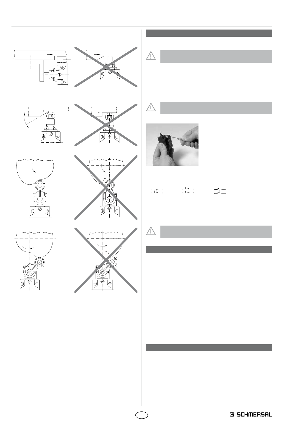
3.4 Actuation of the position switches
Top plunger
A Stop
Roller plunger
max. 30°
Cam disc
4. Electrical connection
4.1 General information for electrical connection
The electrical connection may only be carried out by
authorised personnel in a de-energised condition.
The contact labelling can be found in the wiring compartment of the
switch. For the cable entry, suitable cable glands with an appropriate
degree of protection must be used. After wiring, dust and soiling must
be removed from the wiring compartment. The safety switches with
thermoplastic enclosure of the 236/256 series are double-insulated.
The use of a protective ground connector therefore is not authorised.
According to IEC 60204-1, the versions with connector
must only be used in PELV circuits.
Z/T 236: opening the cover
4.2 Contact variants
The contacts are shown in a non-actuated condition.
front side
Trailing edge
Z/T 235-11Z
Z/T 236-11Z
Z/T 255-11Z
Z/T 256-11Z
Z/T 235-02Z
Z/T 236-02Z
Z/T 255-02Z
Z/T 256-02Z
Position switches with two NO contacts (-20) are not suitable
for safety functions.
T 235-20Z
T 236-20Z
T 255-20Z
T 256-20Z
5. Set-up and maintenance
5.1 Functional testing
The safety function of the safety components must be tested.
The following conditions must be previously checked and met:
1. Check the switch enclosure for damage
2. Check the free movement of the actuating element
3. Check the integrity of the cable entry and connections
5.2 Maintenance
A regular visual inspection and functional test, including the following
steps, is recommended:
1. Check the free movement of the actuating element
2. Remove particles of dust and soiling
3. Check cable entry and connections
Damaged or defective components must be replaced.
6. Disassembly and disposal
6.1 Disassembly
The safety switchgear must be disassembled in a de-energised
condition only.
6.2 Disposal
The safety switchgear must be disposed of in an appropriate manner
in accordance with the national prescriptions and legislations.
4
EN

Operating instructions
Position switches
7. EU Declaration of conformity
EU Declaration of conformity
Z/T 235/236
Z/T 255/256
Original K.A. Schmersal GmbH & Co. KG
We hereby certify that the hereafter described components both in their basic design and construction conform
to the applicable European Directives.
Name of the component: Z/T 235, Z/T 236,
Type: See ordering code
Description of the component: Positive break position switch for safety functions
Relevant Directives: Valid up to
Afxing of the CE conformity mark:
Möddinghofe 30
42279 Wuppertal
Germany
Internet: www.schmersal.com
Z/T 255, Z/T 256
or position switch without safety function
Machinery Directive
Low Voltage Directive
RoHS-Directive
1)
for safety components, whose type plate is
labelled as "Safety component"
2)
for position switches without safety function
1)
2)
April 19, 2016
2006/42/EC
2006/95/EC
2011/65/EU
Valid as of
April 20, 2016
2006/42/EC
2014/35/EU
2011/65/EU
Applied standards: DIN EN 60947-5-1:2010
Person authorised for the compilation
of the technical documentation:
Place and date of issue: Wuppertal, 23 February 01, 2016
ZT235-E-EN
Oliver Wacker
Möddinghofe 30
42279 Wuppertal
Authorised signature
Philip Schmersal
Managing Director
The currently valid declaration of conformity can be
downloaded from the internet at www.schmersal.net.
EN
5

K.A. Schmersal GmbH & Co. KG
Möddinghofe 30, D - 42279 Wuppertal
Postfach 24 02 63, D - 42232 Wuppertal
Phone: +49 - (0)2 02 - 64 74 - 0
Telefax: +49 - (0)2 02 - 64 74 - 1 00
E-Mail: info@schmersal.com
Internet: http://www.schmersal.com
 Loading...