

SRB 031LC/0.6 sec
Operating instructions
Safety-monitoring module
1
EN
EN
Operating instructions...................... pages 1 to 6
Translation of the original operating instructions
1 About this document
1.1 Function
This operating instructions manual provides all the information you need
for the mounting, set-up and commissioning to ensure the safe operation
and disassembly of the safety-monitoring module. The operating instructions must be available in a legible condition and a complete version in
the vicinity of the device.
1.2 Target group: authorised qualied personnel
All operations described in this operating instructions manual must
be carried out by trained specialist personnel, authorised by the plant
operator only.
Please make sure that you have read and understood these operating
instructions and that you know all applicable legislations regarding
occupational safety and accident prevention prior to installation and
putting the component into operation.
The machine builder must carefully select the harmonised standards
to be complied with as well as other technical specications for the
selection, mounting and integration of the components.
1.3 Explanation of the symbols used
Information, hint, note:
This symbol is used for identifying useful additional information.
Caution: Failure to comply with this warning notice could
lead to failures or malfunctions.
Warning: Failure to comply with this warning notice could
lead to physical injury and/or damage to the machine.
1.4 Appropriate use
The products described in these operating instructions are developed to
execute safety-related functions as part of an entire plant or machine. It
is the responsibility of the manufacturer of a machine or plant to ensure
the proper functionality of the entire machinery or plant.
The safety-monitoring module must be exclusively used in accordance
with the versions listed below or for the applications authorised by the
manufacturer. Detailed information regarding the range of applications
can be found in the chapter "Product description".
1.5 General safety instructions
The user must observe the safety instructions in this operating instruc-
tions manual, the country-specic installation standards as well as all
prevailing safety regulations and accident prevention rules.
Further technical information can be found in the Elan
catalogues or in the online catalogue on the Internet:
www.schmersal.net.
The information contained in this operating instructions manual is
provided without liability. Subject to technical modications.
There are no residual risks, provided that the safety instructions as well
as the instructions regarding mounting, commissioning, operation and
maintenance are observed.
1.6 Warning about misuse
In case of inadequate or improper use or manipulations of
the safety-monitoring module, personal hazards or damage
to machinery or plant components cannot be excluded.
The relevant requirements of the standard EN 1088 must
be observed.
14.12.2009 / Index: 471/09 / Teile-Nr. 1180277-EN
Content
1 About this document
1.1 Function . . . . . . . . . . . . . . . . . . . . . . . . . . . . . . . . . . . . . . . . . . . . . .1
1.2 Target group: authorised qualied personnel. . . . . . . . . . . . . . . . . . 1
1.3 Explanation of the symbols used . . . . . . . . . . . . . . . . . . . . . . . . . . .1
1.4 Appropriate use . . . . . . . . . . . . . . . . . . . . . . . . . . . . . . . . . . . . . . . .1
1.5 General safety instructions . . . . . . . . . . . . . . . . . . . . . . . . . . . . . . .1
1.6 Warning about misuse . . . . . . . . . . . . . . . . . . . . . . . . . . . . . . . . . . .1
1.7 Exclusion of liability . . . . . . . . . . . . . . . . . . . . . . . . . . . . . . . . . . . . . 2
2 Product description
2.1 Ordering code . . . . . . . . . . . . . . . . . . . . . . . . . . . . . . . . . . . . . . . . .2
2.2 Special versions. . . . . . . . . . . . . . . . . . . . . . . . . . . . . . . . . . . . . . . . 2
2.3 Destination and use . . . . . . . . . . . . . . . . . . . . . . . . . . . . . . . . . . . . .2
2.4 Technical data . . . . . . . . . . . . . . . . . . . . . . . . . . . . . . . . . . . . . . . . .2
2.5 Safety classication . . . . . . . . . . . . . . . . . . . . . . . . . . . . . . . . . . . . .3
3 Mounting
3.1 General mounting instructions . . . . . . . . . . . . . . . . . . . . . . . . . . . . .3
3.2 Dimensions . . . . . . . . . . . . . . . . . . . . . . . . . . . . . . . . . . . . . . . . . . .3
4 Electrical connection
4.1 General information for electrical connection. . . . . . . . . . . . . . . . . .3
5 Operating principle and settings
5.1 LED functions. . . . . . . . . . . . . . . . . . . . . . . . . . . . . . . . . . . . . . . . . .3
5.2 Terminal description (see Fig. 1) . . . . . . . . . . . . . . . . . . . . . . . . . . . 3
6 Set-up and maintenance
6.1 Functional testing. . . . . . . . . . . . . . . . . . . . . . . . . . . . . . . . . . . . . . . 3
6.2 Maintenance . . . . . . . . . . . . . . . . . . . . . . . . . . . . . . . . . . . . . . . . . .3
7 Disassembly and disposal
7.1 Disassembly. . . . . . . . . . . . . . . . . . . . . . . . . . . . . . . . . . . . . . . . . . .4
7.2 Disposal . . . . . . . . . . . . . . . . . . . . . . . . . . . . . . . . . . . . . . . . . . . . . .4
8 Appendix
8.1 Wiring examples . . . . . . . . . . . . . . . . . . . . . . . . . . . . . . . . . . . . . . .4
8.2 Start conguration . . . . . . . . . . . . . . . . . . . . . . . . . . . . . . . . . . . . . . 4
8.3 Sensor conguration . . . . . . . . . . . . . . . . . . . . . . . . . . . . . . . . . . . .4
8.4 Actuator conguration . . . . . . . . . . . . . . . . . . . . . . . . . . . . . . . . . . .5
8.5 EC Declaration of conformity . . . . . . . . . . . . . . . . . . . . . . . . . . . . . .6

2
Operating instructions
Safety-monitoring module SRB 031LC/0,6 sec
EN
1.7 Exclusion of liability
We shall accept no liability for damages and malfunctions resulting from
defective mounting or failure to comply with this operating instructions
manual. The manufacturer shall accept no liability for damages resulting
from the use of unauthorised spare parts or accessories.
For safety reasons, invasive work on the device as well as arbitrary re-
pairs, conversions and modications to the device are strictly forbidden;
the manufacturer shall accept no liability for damages resulting from
such invasive work, arbitrary repairs, conversions and/or modications
to the device.
2 Product description
2.1 Ordering code
This operating instructions manual applies to the following types:
SRB 031LC/0.6 sec
Factory-set drop-out delay: 0.6 seconds
Only if the information described in this operating instructions
manual are realised correctly, the safety function and therefore
the compliance with the Machinery Directive is maintained.
2.2 Special versions
For special versions, which are not listed in the order code below 2.1,
these specications apply accordingly, provided that they correspond to
the standard version.
2.3 Destination and use
The safety-monitoring modules for integration in safety circuits are
designed for tting in control cabinets. They are used for the safe
evaluation of the signals of positive break position switches or magnetic
safety sensors for safety functions on sliding, hinged and removable
safety guards as well as emergency stop control devices and AOPD's.
The safety function is dened as the delayed opening of the enabling
circuits 17-18, 27-28 and 37-38 when the inputs S11-S12 and/or
S11-S22 are opened. The safety relevant current paths with the output
contacts 17-18, 27-28 and 37-38 meet the following requirements under
observation of a B
10d
value assessment (also refer to "Requirements to
DIN EN ISO 13849-1"):
– control category 3 – PL d to DIN EN ISO 13849-1
– corresponds to SIL 2 to DIN EN 61508-2
– corresponds to SILCL 3 to DIN EN 62061
(corresponds to control category 4 to DIN EN 954-1)
To determine the Performance Level (PL) of the entire safety function
(e.g. sensor, logic, actuator) to DIN EN ISO 13849-1, an analysis of all
relevant components is required.
2.4 Technical data
General data:
Standards: IEC/EN 60204-1, EN 60947-5-1;
EN ISO 13849-1, IEC/EN 61508
Climate resistance: EN 60068-2-78
Fixing: Snaps onto standard DIN rails
to DIN EN 60715
Terminal designations: EN 60947-1
Material of the enclosure: glass-bre reinforced thermoplastic,
ventilated
Material of the contacts: AgSnO, self-cleaning, positive drive
Weight: 230 g
Start conditions Automatic or start button
Feedback circuit (Y/N): Yes
Drop-out delay: 600 ms ± 30%
Pull-in delay: ≤ 30 ms
Mechanical data:
Connection type: Screw terminals
Cable section: min. 2 mm
2
/ max. 2 mm
2
Connecting cable: rigid or exible
Tightening torque
for the terminals:
0.6 Nm
With removable terminals (Y/N): No
Mechanical life: 10 million operations
Electrical life: Derating curve available on request
Resistance to shock: 10 g / 11 ms
Resistance to vibrations
to EN 60068-2-6:
10 ... 55 Hz, amplitude 0.35 mm
Ambient conditions:
Ambient temperature: –25°C … +45°C
Storage and transport
temperature:
–40°C … +85°C
Protection class: Enclosure: IP 40,
Terminals: IP 20,
Wiring compartment: IP 54
Air clearances and creepage
distances to IEC/EN 60664-1:
4 kV/2 (basic insulation)
EMC rating: to EMC Directive
Electrical data:
Contact resistance in new state: max. 100 mΩ
Power consumption: max. 1.7 W / 1.9 VA
Rated operating voltage U
e
: 24 VDC –15%/+20%,
residual ripple max. 10%
Max. fuse rating of the
operating voltage:
internal F1: T 1.25 A
Monitored inputs:
Cross-wire detection (Y/N): No
Wire breakage detection (Y/N): Yes
Earth leakage detection (Y/N): Yes
Number of NO contacts: 0
Number of NC contacts: 2
Cable lengths: 1,500 m with 1.5 mm²
2,500 m with 2.5 mm²
Conduction resistance: max. 40 Ω
Outputs:
Number of safety contacts: 3
Number of auxiliary contacts: 1
Number of signalling outputs: 0
Switching capacity of the
safety contacts:
17-18; 27-28; 37-38:
max. 250 V, 6 A ohmic (inductive in
case of appropriate protective wiring)
Switching capacity of the
auxiliary contacts:
45-46: 24 VDC / 2 A
Fuse rating of the
safety contacts:
6.3 A slow blow
Recommended fuse for
the auxiliary contacts:
2 A slow blow
Utilisation category to
EN 60947-5-1:
AC-15 / DC-13: EN 60947-5-1
Dimensions (H/W/D): 100 mm x 22.5 mm x 121 mm
The data specied in this manual are applicable when the component
is operated with rated operating voltage U
e
±0%.

3
SRB 031LC/0,6 sec
Operating instructions
Safety-monitoring module
EN
2.5 Safety classication
Standards: EN ISO 13849-1, IEC 61508,
EN 60947-5-1
PL: Stop 1: up to d
Control category: Stop 1: up to 3
DC: Stop 1: < 66% (low)
CCF: > 65 points
SIL: Stop 1: up to 2
Service life: 20 years
B10d value (for one channel): Low voltages range 20%: 20,000,000
40%: 7,500,000
60%: 2,500,000
80%: 1,000,000
Maximum load 100%: 400,000
MTTF
B d x x
h
s/h3600
d
10d op op
op
n
0,1 x n
op
t
cycle
For an average annual demand rate of nop = 126,720 cycles
per year,
Performance Level PL e can be obtained at maximum load.
nop = average number of activations per year
dop = average number of operating days per year
hop = average number of operating hours per day
t
cycle
= average demand rate of the safety function in s
(e.g. 4 × per hour = 1 × per 15 min. = 900 s)
(Specications can vary depending on the application-specic
parameters hop, dop and t
cycle
as well as the load.)
3 Mounting
3.1 General mounting instructions
Mounting: snaps onto standard DIN rails to EN 60715.
Snap the bottom of the enclosure slightly tilted forwards in the
DIN rail and push up until it latches in position.
3.2 Dimensions
All measurements in mm.
Device dimensions (H/W/D): 100 x 22.5 x 121 mm
4 Electrical connection
4.1 General information for electrical connection
Wiring examples: see appendix
The electrical connection may only be carried out by
authorised personnel in de-energised condition.
5 Operating principle and settings
5.1 LED functions
• K1: Status channel 1
• K2: Status channel 2
• UB: Status operating voltage (LED is on, when the operating
voltage on the terminals A1-A2 is ON)
• Ui: Status internal operating voltage (LED is on, when the
operating voltage on the terminals A1-A2 is ON and the fuse
has not been triggered)
5.2 Terminal description (see Fig. 1)
Voltages: A1
A2
+24 VDC/24 VAC
0 VDC/24 VAC
Inputs: S11-S12
S11-S22
Input channel 1 (+)
Input channel 2 (+)
Outputs: 17-18
27-28
37-38
First safety enabling circuit (STOP 1)
Second safety enabling circuit (STOP 1)
Third safety enabling circuit (STOP 1)
Start: X1-X2
45-46
Feedback circuit and external reset
Auxiliary NC contact
U
B
U
i
K1
K2
SRB
031LC/
0,6s
37 27 17 45
X1 S12 S11 A1
38 28 18 46
X2 S22 A2
Fig. 1
6 Set-up and maintenance
6.1 Functional testing
The safety function of the safety-monitoring module must be tested.
The following conditions must be previously checked and met:
1. Correct xing
2. Check the integrity of the cable entry and connections
3. Check the safety-monitoring module's enclosure for damage.
4. Check the electrical function of the connected sensors and
their inuence on the safety-monitoring module and the
downstream actuators
6.2 Maintenance
A regular visual inspection and functional test, including the following
steps, is recommended:
1. Check the correct xing of the safety-monitoring module
2. Check the cable for damages
3. Check electrical function
Damaged or defective components must be replaced.
4
Operating instructions
Safety-monitoring module SRB 031LC/0,6 sec
EN
8.3 Sensor conguration
Single-channel emergency stop circuit with command devices
to DIN EN ISO 13850 (EN 418) and EN 60947-5-5 (Fig. 5)
• Wire breakage and earth leakage in the control circuits are detected.
• Possible control categories:
– 1 to EN 954-1
– 2 – PL d to DIN EN ISO 13849-1
Dual-channel emergency stop circuit with command devices
to DIN EN ISO 13850 (EN 418) and EN 60947-5-5 (Fig. 6)
• Wire breakage and earth leakage in the control circuits are detected.
• Cross-wire shorts between the control circuits are not detected.
• Possible control categories:
– 3 to EN 954-1
– 4 to EN 954-1 (with protected cable laying)
– 4 – PL e to DIN EN ISO 13849-1 (with protected cable laying)
S12
S11
S22
S12
S12
S11
S22
S11
Fig. 5 Fig. 6
Single-channel guard door monitoring circuit with interlocking
devices to EN 1088 (Fig. 7)
• At least one contact with positive break required
• Wire breakage and earth leakage in the control circuits are detected.
• Possible control categories:
– 1 to EN 954-1
– 2 – PL d to DIN EN ISO 13849-1
Dual-channel guard door monitoring circuit with interlocking
device to EN 1088 (Fig. 8)
• At least one contact with positive break required
• Wire breakage and earth leakage in the control circuits are detected.
• Cross-wire shorts between the monitoring circuits are not detected.
• Possible control categories:
– 3 to EN 954-1
– 4 to EN 954-1 (with protected cable laying)
– 4 – PL e to DIN EN ISO 13849-1 (with protected cable laying)
S12
S11
S22
S12
S12
S11
S22
S11
Fig. 7 Fig. 8
7 Disassembly and disposal
7.1 Disassembly
The safety-monitoring module must be disassembled in a de-energised
condition only.
7.2 Disposal
The safety-monitoring module must be disposed of in an appropriate
manner in accordance with the national prescriptions and legislations.
8 Appendix
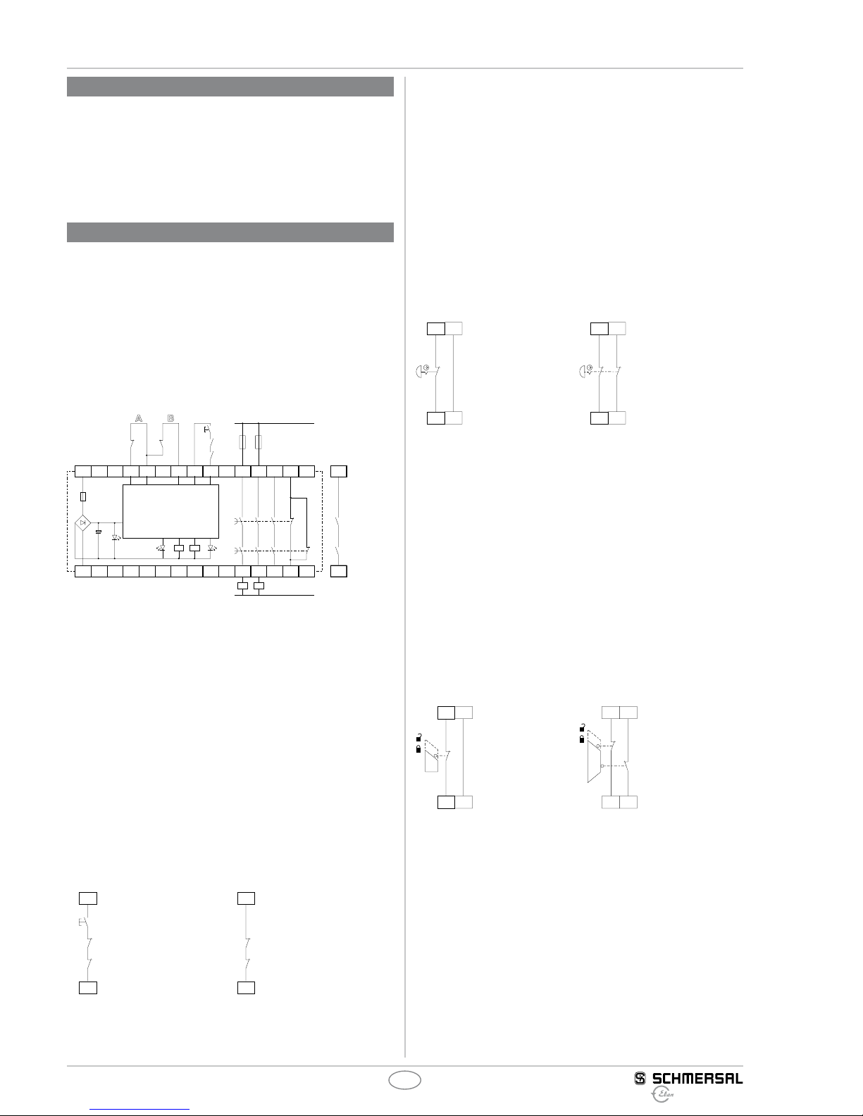
8.1 Wiring examples
Dual-channel control, shown for a guard door monitor; with two
contacts A and B, where at least one is a positive break contact;
with external reset button J (see Fig. 2)
• Relay outputs: Suitable for 2-channel control, for increase in capacity
or number of contacts by means of contactors or relays with positiveguided contacts.
• The control system recognises wire-breakage and earth faults in
the monitoring circuit.
• S = Feedback circuit
S12 S11 S22 X1 X2 17 27 37A1
A2 18 28 38
J
S
K
B
L1
N
K
A
Ui
F1
K2K1
K1
K2
45
46
K
A
K
A
K
B
K
B
a)
Fig. 2 a) Logic
8.2 Start conguration
External reset button (non-monitored start) (see Fig. 3)
• The external reset button is integrated in the feedback circuit in series.
• The safety-monitoring module is activated upon actuation of the reset
button.
Automatic start (see Fig. 4)
• The automatic start is programmed by connecting the feedback circuit
to the terminals X1/X2. If the feedback circuit is not required, establish
a bridge.
• Caution: Not admitted without additional measure due to the risk of
gaining access by stepping behind!
• When the SRB 031LC / 0.6 sec safety-monitoring module is used
with the operating mode "Automatic start", an automatic restart after a
shutdown in case of emergency must be prevented by the upstream
control to EN 60204-1 paragraph 9.2.5.4.2 and 10.8.3.
X2
X1
K
A
J
K
B
X2
X1
K
A
K
B
Fig. 3 Fig. 4

5
SRB 031LC/0,6 sec
Operating instructions
Safety-monitoring module
EN
8.4 Actuator conguration
Single-channel control (see Fig. 9)
• Suitable for increase in capacity or number of contacts by means of
contactors or relays with positive-guided contacts.
• If the feedback circuit
is not required, establish a bridge.
• S = Feedback circuit and external reset in serie
Dual-channel control with feedback circuit (Fig. 10)
• Suitable for increase in capacity or number of contacts by means of
contactors or relays with positive-guided contacts.
• If the feedback circuit is not required, establish a bridge.
• S = Feedback circuit and external reset in serie
X1 X2 17
18
K
A
K
A
K
A
S
L1
N
X1 X2 17
18
K
B
K
A
K
B
K
A
K
B
L1
N
K
A
S
Fig. 9 Fig. 10

6
Operating instructions
Safety-monitoring module SRB 031LC/0,6 sec
EN
SRB031LC-B-EN
8.5 EC Declaration of conformity
EC Declaration of conformity
Translation of the original declaration of conformity
valid as of December 29, 2009
Elan Schaltelemente GmbH & Co. KG
Im Ostpark 2 · 35435 Wettenberg
Germany
Internet: www.elan.de
We hereby certify that the hereafter described safety components both in its basic design and
construction conforms to the applicable European Directives.
Place and date of issue: Wuppertal, October 6, 2009
Authorised signature
Heinz Schmersal
Managing Director
Name of the safety component: SRB 031LC
Description of the safety component: Safety-monitoring module for emergency
stop circuits and guard door monitoring
Harmonised EC-Directives: 2006/42/EC EC-Machinery Directive
2004/108/EC EMC-Directive
Person authorized for the compilation of the
technical documentation:
Ulrich Loss
Möddinghofe 30
42279 Wuppertal
Notied body, which approved the full quality
assurance system, referred to in Appendix X,
2006/42/EC:
TÜV Rheinland Industrie Service GmbH
Alboinstraße 56
12103 Berlin
ID n°: 0035
Elan Schaltelemente GmbH & Co. KG
Im Ostpark 2, D - 35435 Wettenberg
Postfach 1109, D - 35429 Wettenberg
Telefon: +4 9 (0)6 41 9848-0
Telefax: +49 (0)641 9848-420
E-Mail: info-elan@schmersal.com
Internet: www.elan.de
Appendix
Note
The currently valid declaration of conformity can be
downloaded from the internet at www.schmersal.net.
 Loading...