


EN
Operating instructions. . . . . . . . . . . .pages 1 to 20
Original
SLC 420
SLG 420
Operating instructions
Safety light curtain/safety light grid
EN
1
1. About this document
1.1 Function
This operating instructions manual provides all the information you
need for the mounting, set-up and commissioning to ensure the safe
operation and disassembly of the safety switchgear. The operating
instructions must be available in a legible condition and a complete
version in the vicinity of the device.
1.2 Target group: authorised qualified personnel
All operations described in this operating instructions manual must
be carried out by trained specialist personnel, authorised by the plant
operator only.
Please make sure that you have read and understood these operating
instructions and that you know all applicable legislations regarding
occupational safety and accident prevention prior to installation and
putting the component into operation.
The machine builder must carefully select the harmonised standards
to be complied with as well as other technical specifications for the
selection, mounting and integration of the components.
Content
1 About this document
1.1 Function.............................................1
1.2 Target group: authorised qualied personnel ................1
1.3 Explanation of the symbols used..........................2
1.4 Appropriate use.......................................2
1.5 General safety instructions ..............................2
1.6 Warning about misuse..................................2
1.7 Exclusion of liability ....................................2
2 Product description
2.1 Ordering code . . . . . . . . . . . . . . . . . . . . . . . . . . . . . . . . . . . . . . . .2
2.1.1 Safety light curtain (Standard)............................2
2.1.2 Safety light grid (Standard) . . . . . . . . . . . . . . . . . . . . . . . . . . . . . . 2
2.1.3 Safety light curtain (IP69K) . . . . . . . . . . . . . . . . . . . . . . . . . . . . . . 2
2.1.4 Safety light grid (IP69K) ................................2
2.2 Special versions ......................................3
2.3 Included in delivery . . . . . . . . . . . . . . . . . . . . . . . . . . . . . . . . . . . .3
2.3.1 Included in delivery of SLC/SLG 420 Standard...............3
2.3.2 Included in delivery of SLC/SLG 420 IP69K . . . . . . . . . . . . . . . . . 3
2.4 Destination and use....................................3
2.5 Technical data ........................................3
2.5.1 Technical data IP69K (additions)..........................3
2.6 Response time (reaction time) ...........................4
2.7 Effective resolution ....................................4
2.8 Safety classication....................................5
2.9 Functions............................................5
2.9.1 Protective mode ......................................5
2.9.2 Restart interlock (manual reset) ..........................5
2.9.3 Fixed blanking SLC 420 ................................5
2.9.4 Floating blanking SLC 420 ..............................6
2.9.5 Floating blanking SLG 420 ..............................6
2.9.6 Contactor control (EDM) . . . . . . . . . . . . . . . . . . . . . . . . . . . . . . . . 6
2.9.7 Start interlock ........................................7
2.10 Self-test .............................................7
2.11 Beam coding A .......................................7
3 Mounting
3.1 General conditions ....................................7
3.2 Protection eld and approach . . . . . . . . . . . . . . . . . . . . . . . . . . . .7
3.3 Alignment ...........................................8
3.4 Setting mode .........................................8
3.5 Safety distance .......................................8
3.5.1 Minimum distance to reecting surfaces ...................11
3.6 Dimensions . . . . . . . . . . . . . . . . . . . . . . . . . . . . . . . . . . . . . . . . .12
3.6.1 Dimensions transmitter and receiver SLC 420 (Standard) .....12
3.6.2 Dimensions transmitter and receiver SLG 420 (Standard) . . . . . 12
3.6.3 Dimensions transmitter and receiver SLC 420 IP69K .........13
3.6.4 Dimensions transmitter and receiver SLG 420 IP69K.........13
3.7 Scope of delivery and accessories .......................14
3.7.1 Included in delivery . . . . . . . . . . . . . . . . . . . . . . . . . . . . . . . . . . . 14
3.7.2 Optional accessories ..................................14
4 Electrical connection
4.1 Wiring example default................................15
4.2 Activation of the contactor control (EDM) without PC software..16
4.3 Connector conguration Receiver, Transmitter & Cable .......16
5 Set-up and maintenance
5.1 Check before start-up .................................17
5.2 Maintenance ........................................17
5.3 Regular check .......................................17
5.4 Half-yearly inspection .................................17
5.5 Cleaning ...........................................17
6 Diagnostic
6.1 LED status information ................................18
6.2 Fault diagnostic ......................................19
6.3 Extended diagnostic ..................................19
7 Disassembly and disposal
7.1 Disassembly ........................................19
7.2 Disposal............................................19
8 Appendix
8.1 Contact ............................................19
9 EU Declaration of conformity
x.000 / 09.2016 / v.A. - 103010741-EN / B / 2016-09-21 / AE-Nr. 6553
Version 2.0
2
Operating instructions
Safety light curtain/safety light grid
SLC 420
SLG 420
EN
1.3 Explanation of the symbols used
Information, hint, note:
This symbol is used for identifying useful additional information.
Caution: Failure to comply with this warning notice could
lead to failures or malfunctions.
Warning: Failure to comply with this warning notice could
lead to physical injury and/or damage to the machine.
1.4 Appropriate use
The products described in these operating instructions are developed to
execute safety-related functions as part of an entire plant or machine. It
is the responsibility of the manufacturer of a machine or plant to ensure
the correct functionality of the entire machine or plant.
The safety switchgear must be exclusively used in accordance with
the versions listed below or for the applications authorised by the
manufacturer. Detailed information regarding the range of applications
can be found in the chapter "Product description".
1.5 General safety instructions
The user must observe the safety instructions in this operating
instructions manual, the country-specific installation standards as well
as all prevailing safety regulations and accident prevention rules.
Further technical information can be found in the Schmersal
catalogues or in the online catalogue on the Internet:
www.schmersal.net.
The information contained in this operating instructions manual is
provided without liability and is subject to technical modifications.
The entire concept of the control system, in which the
safety component is integrated, must be validated to
EN ISO 13849-2.
There are no residual risks, provided that the safety instructions as well
as the instructions regarding mounting, commissioning, operation and
maintenance are observed.
Additional measures could be required to ensure that the electrosensitive device does not present a dangerous breakdown, when other
forms of light beams are available in a special application (e.g. use
of wireless control devices on cranes, radiation of welding sparks or
effects of stroboscopic lights).
1.6 Warning about misuse
In case of improper use or manipulation of the safety
switchgear, personal hazards or damages to machinery or
plant components cannot be excluded when safety switchgear is used. The relevant requirements of the standard
EN ISO 13855 must be observed.
Only if the information described in this operating instructions
manual are realised correctly, the safety function and therefore
the compliance with the Machinery Directive is maintained.
1.7 Exclusion of liability
We shall accept no liability for damages and malfunctions resulting from
defective mounting or failure to comply with this operating instructions
manual. The manufacturer shall accept no liability for damages
resulting from the use of unauthorised spare parts or accessories.
For safety reasons, invasive work on the device as well as arbitrary
repairs, conversions and modifications to the device are strictly
forbidden; the manufacturer shall accept no liability for damages
resulting from such invasive work, arbitrary repairs, conversions and/or
modifications to the device.
2. Product description
2.1 Ordering code
This operating instructions manual applies to the following types:
2.1.1 Safety light curtain (Standard)
SLC420-E/R➀-➁-RFB-
➂
No. Option Description
➀
xxxx Protection field heights in mm available lengths:
0170, 0250, 0330, 0410, 0490, 0570, 0650, 0730,
0810, 0890, 0970, 1050, 1130, 1210, 1290, 1370,
1450, 1530*, 1610*, 1690*, 1770*
➁
14 Resolution 14 mm
30 Resolution 30 mm
50 Resolution 50 mm
➂
Range 0,3 m ... 7 m
only for resolution 14 mm
Range 0,3 m ... 10 m
only for resolution 30 and 50 mm
H Range 0,3 m ... 18 m, High range
only for resolution 30 mm
Note
* Protection field heights from 1530 to 1770 mm
only with resolution of 30 and 50 mm
2.1.2 Safety light grid (Standard)
SLG420-E/R➀-RF-
➁
No. Option Description
➀
Distance between outermost beams:
0500-02 500 mm, 2-beam
0800-03 800 mm, 3-beam
0900-04 900 mm, 4-beam
➁
Range 0,3 m ... 18 m
H Range 8 m ... 50 m, High range
2.1.3 Safety light curtain (IP69K)
SLC420-E/R➀-➁-69-RFB
No. Option Description
➀
xxxx Protection field heights in mm available
lengths: 0170, 0250, 0330, 0410, 0490,
0570, 0650, 0730, 0810, 0890, 0970, 1050,
1130, 1210, 1290, 1370, 1450
➁
14 Resolution 14 mm
with a range of 0.3 m … 7 m
30 Resolution 30 mm
with a range of 0.3 m … 10 m
2.1.4 Safety light grid (IP69K)
SLG420-E/R➀-69-RF
No. Option Description
➀
Distance between outermost beams:
0500-02 500 mm, 2-beam
0800-03 800 mm, 3-beam
0900-04 900 mm, 4-beam
Range 0,3 m ... 18 m

3
SLC 420
SLG 420
Operating instructions
Safety light curtain/safety light grid
EN
2.2 Special versions
For special versions, which are not listed in the order code below 2.1,
these specifications apply accordingly, provided that they correspond to
the standard version.
2.3 Included in delivery
2.3.1 Included in delivery of SLC/SLG 420 Standard
- Sensors E, R
- Mounting kit MS-1030
- Test rod
- Operating instructions DE/EN
2.3.2 Included in delivery of SLC/SLG 420 IP69K
- Sensors E, R
- Mounting kit MS-1038
- 5 m long connection cable,
permanently integrated on the transmitter and receiver
- Test rod
- Operating instructions DE/EN
2.4 Destination and use
The SLC 420 is a non-contact, self-testing safety guard, which is used
for the protection of hazardous points, hazardous areas and machine
accesses. If one or more light beams are interrupted, the hazardous
movement must be stopped.
The user must evaluate and design the safety chain in
accordance with the relevant standards and the required
safety level.
2.5 Technical data
Standards: EN 61496-1; EN 61496-2;
EN ISO 13849; EN 62061
Material of the enclosure: Aluminium
Number of beams: 2 … 144 beams
Protection field heights:
- SLC 420 with resolution 14 mm: 170 mm … 1450 mm,
- SLC 420 with resolution 30 mm: 170 mm … 1770 mm,
- SLC 420 with resolution 50 mm: 170 mm … 1770 mm,
- SLG 420: 500 mm, 800 mm, 900 mm
Detection ability for test rod:
- SLC 420: 14 mm, 30 mm, 50 mm
- SLG 420: 2 beams with resolution 500 mm 1)
3 beams with resolution 400 mm 1)
4 beams with resolution 300 mm
1)
Range of the protection field:
- SLC 420 with resolution 14 mm: 0.3 … 7.0 m
- SLC 420 with resolution 30 und 50 mm: 0.3 … 10.0 m
- SLC 420 with resolution 30 mm (High range): 0.3 … 18.0 m
- SLG 420: 0.3 … 18.0 m
- SLG 420 (High range): 8.0 … 50.0 m
Response time:
- Beam coding (normal): 1 - 48 beams = 10 ms
49 - 144 beams = 20 ms
- Beam coding A: 1 - 48 beams = 15 ms
49 - 144 beams = 27 ms
Rated operating voltage: 24 VDC ±10% (PELV) supply unit
to EN 60204 (power drop > 20 ms)
Rated operating current: 250 mA max. + 2 x 250 mA each OSSD
Wave length of the sensor: 870 nm
Safety outputs:
Test cycle time: 750 ms
Test impulse length: 200 µs
Safety outputs: 2 x PNP-type semi-conductor,
short-circuit proof
Switching voltage HIGH 2): 15 … 26.4 V
Switching voltage LOW 2): 0 … 2 V
Switching current: 0 ... 250 mA
Leakage current 3): 1 mA
Load capacity: 200 nF
Load capacity 4): 2 H
Admissible conduction resistance between OSSD and load: 2.5 Ω
Supply cable: 1 Ω
Contactor control (EDM):
Input voltage HIGH (inactive): 17 … 26.4 V
Input voltage LOW (active): 0 … 2 V
Input current HIGH: 3 … 10 mA
Input current LOW: 0 … 2 mA
Input restart interlock
Input voltage HIGH (active): 17 … 26.4 V
Input voltage LOW (inactive): 0 … 2 V
Input current HIGH: 3 … 10 mA
Input current LOW: 0 … 3 mA
Functions: contactor control,
beam blanking fixed and floating,
setting mode
Operating modes: protective mode,
start and restart interlock
Signal times:
- Contactor control: 50 … 500 ms, adjustable
- Authorized operation restart interlock: 100 ms to 1500 ms,
Signal acquisition with falling edge
- Start interlock: 250 … 1500 ms, adjustable
LED indications:
- Transmitter: Transmitting, status
- Receiver: OSSD ON, OSSD OFF, restart,
signal reception, blanking, multifunction
Connection: M12 connector plug with metal thread,
receiver 8-pole, transmitter 4-pole
Ambient temperature: −25° C … + 50° C
at −25° C: Reduction of range by −10%
Storage temperature: −25° C … + 70° C
Interface: Diagnostics and function setting
Protection class: IP67 (IEC 60529)
Resistance to vibration: 10 … 55 Hz to IEC 60068-2-6
Resistance to shock: 10 g, 16 ms, to IEC 60028-2-29
Year of construction: as of 2015 version 2.0
1)
Resolution = beam distance + beam diameter 10 mm
2)
To EN 61131-2
3)
In case of failure, the leakage current flows to the OSSD cable.
The downstream control element must recognise this state as LOW.
A safety PLC must detect this state.
4)
The load induction generates an induced voltage during the
switch-off, which compromises the downstream components
(spark quenching element).
2.5.1 Technical data IP69K (additions)
For the IP69K versions, the same technical data is valid as described in
point 2.5, with the exception of the following details:
Material of the enclosure: Aluminium
- Protective tube: PMMA plastic tubes
- End plugs: PA 6
- Membrane: V4A, Gore Tex membrane M12 x 1.5
Protection field heights:
- SLC 420 IP69K with resolution 14 mm: 170 mm … 1450 mm
- SLC 420 IP69K with resolution 30 mm: 170 mm … 1450 mm
- SLG 420 IP69K: 500 mm, 800 mm, 900 mm
Range of the protection field:
- SLC 420 IP69K with resolution 14 mm: 0.3 … 7 m
- SLC 420 IP69K with resolution 30 mm: 0.3 … 10 m
- SLG 420 IP69K: 0.3 … 18 m
Connection: screwed cable gland M16 x 1.5
cable connector M12 x 1; 4-pole fixed to transmitter,
M12 x 1; 8-pole fixed to receiver integrated
Ambient temperature: −10° C … +50° C
Protection class: IP69K
4
Operating instructions
Safety light curtain/safety light grid
SLC 420
SLG 420
EN
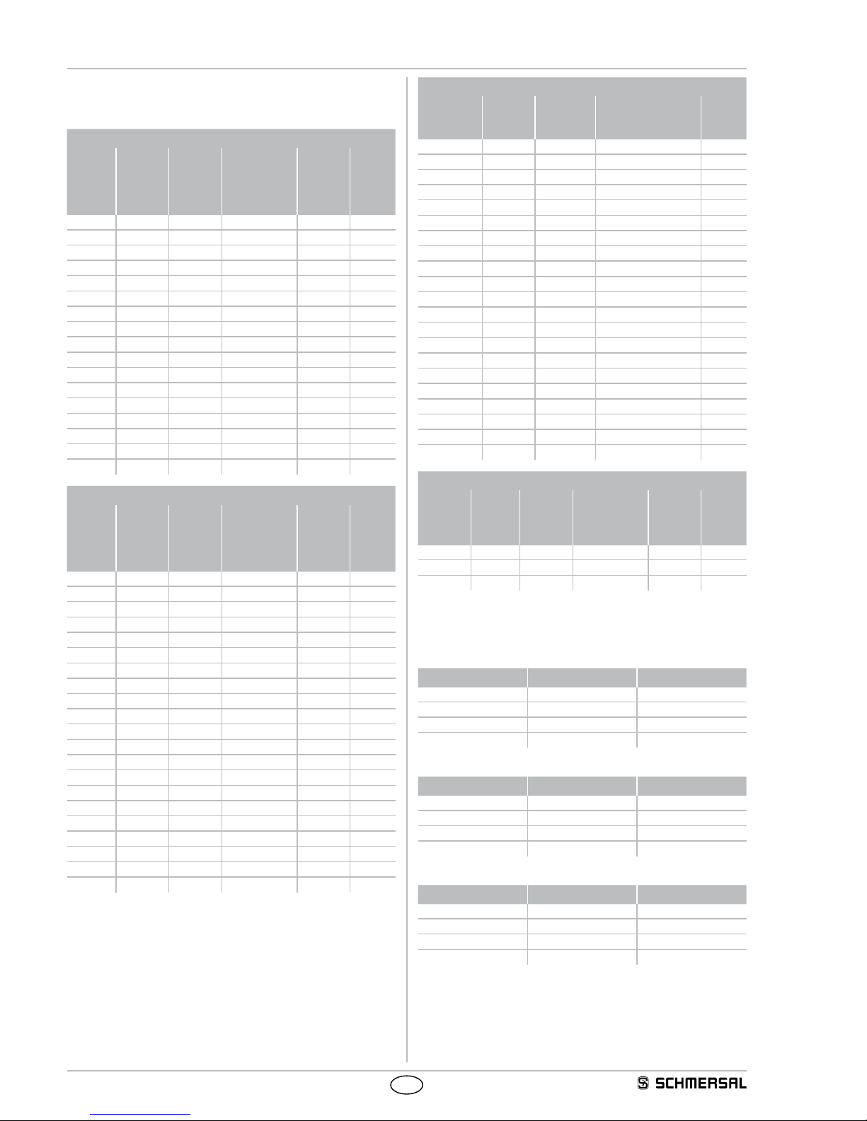
2.6 Response time (reaction time)
The response time depends on the hight of the protection field, the
resolution, the number of light beams and the beam coding.
SLC 420 Resolution 14 mm
Pro-
tection
field
height
[mm]
Beams
[Number]
Res-
ponse
time
[ms]
Response
time with
beam coding
A
[ms]
Weight
Standard
[kg]
Weight
IP69K
[kg]
170 16 10 15 0.9 1.6
250 24 10 15 1.2 1.9
330 32 10 15 1.5 2.3
410 40 10 15 1.8 2.6
490 48 10 15 2.0 3.0
570 56 20 27 2.3 3.3
650 64 20 27 2.5 3.7
730 72 20 27 2.8 4.1
810 80 20 27 3.1 4.5
890 88 20 27 3.4 4.8
970 96 20 27 3.6 5.2
1050 104 20 27 3.9 5.6
1130 112 20 27 4.2 6.0
1210 120 20 27 4.5 6.4
1290 128 20 27 4.7 6.8
1370 136 20 27 5.0 7.2
1450 144 20 27 5.2 7.6
SLC 420 Resolution 30 mm
Pro-
tection
field
height
[mm]
Beams
[Number]
Res-
ponse
time
[ms]
Response
time with
beam coding
A
[ms]
Weight
Standard
[kg]
Weight
IP69K
[kg]
170 8 10 15 0.9 1.6
250 12 10 15 1.2 1.9
330 16 10 15 1.5 2.3
410 20 10 15 1.8 2.6
490 24 10 15 2.0 3.0
570 28 10 15 2.3 3.3
650 32 10 15 2.5 3.7
730 36 10 15 2.8 4.1
810 40 10 15 3.1 4.5
890 44 10 15 3.4 4.8
970 48 10 15 3.6 5.2
1050 52 20 27 3.9 5.6
1130 56 20 27 4.2 6.0
1210 60 20 27 4.5 6.4
1290 64 20 27 4.7 6.8
1370 68 20 27 5.0 7.2
1450 72 20 27 5.2 7.6
1530 76 20 27 5.5 ---
1610 80 20 27 5.8 ---
1690 84 20 27 6.1 ---
1770 88 20 27 6.3 ---
SLC 420 Resolution 50 mm
Protection
field height
[mm]
Beams
[Number]
Response
time
[ms]
Response time with
Beam coding A
[ms]
Weight
[kg]
170 4 10 15 0.9
250 6 10 15 1.2
330 8 10 15 1.5
410 10 10 15 1.8
490 12 10 15 2.0
570 14 10 15 2.3
650 16 10 15 2.5
730 18 10 15 2.8
810 20 10 15 3.1
890 22 10 15 3.4
970 24 10 15 3.6
1050 26 10 15 3.9
1130 28 10 15 4.2
1210 30 10 15 4.5
1290 32 10 15 4.7
1370 34 10 15 5.0
1450 36 10 15 5.2
1530 38 10 15 5.5
1610 40 10 15 5.8
1690 42 10 15 6.1
1770 44 10 15 6.3
SLG 420
Beams
[Number]
Beam
dis-
tance
[mm]
Res-
ponse
time
[ms]
Response time
with beam
coding A
[ms]
Weight
Standard
[kg]
Weight
IP69K
[kg]
2 500 10 15 2.5 3.7
3 400 10 15 3.5 5.1
4 300 10 15 3.6 5.2
2.7 Effective resolution
The effective resolution in case of activated blanking of floating beams
can be found in the following table:
Blanked beams Physical resolution Effective resolution
1 14 24
2 14 34
3 14 44
4 14 54
Blanked beams Physical resolution Effective resolution
1 30 48
2 30 68
3 30 88
4 30 108
Blanked beams Physical resolution Effective resolution
1 50 88
2 50 128
3 50 168
4 50 208
5
SLC 420
SLG 420
Operating instructions
Safety light curtain/safety light grid
EN
2.8 Safety classification
Standards: EN ISO 13849-1, EN 62061
PL: up to e
Control category: up to 4
PFH value: 6.19 x 10⁻⁹ / h
SIL: up to 3
Service life: 20 years
2.9 Functions
The system consists of a receiver and a transmitter. For the described
functions, no further switching elements are required. For the
diagnostics and function selection, a PC-software is offered as an
accessory.
For the diagnostics or the setting of parameters with a PC, the BUS
converter NSR-0801 is required (not included in scope of delivery).
The system has the following features:
• Protective mode (automatic start after release of the protection field)
• Start interlock
• Restart Interlock (manual reset)
• Contactor control (EDM)
• Beam coding
• Blanking of fixed protection field areas
• Blanking of movable protection field areas
Factory setting
The system features many functions without needing any additional
devices. The following table gives an overview of the possible functions
and the factory settings configuration.
Function Factory
setting
Configuration
Protective mode not active External wiring
Restart interlock
(manual reset)
not active External wiring
Blanking
fixed/floating
not active With BUS converter
NSR-0801 and PC-software
Contactor control
(EDM)
not active With BUS converter
NSR-0801 and PC-software
Start interlock not active With BUS converter
NSR-0801 and PC-software
Beam coding A not active With BUS converter
NSR-0801 and PC-software
2.9.1 Protective mode
The protective mode switches the OSSD outputs to ON state
(protection field not interrupted), without external release of a switching
device. The protected operation is activated with an electrical
connection between pin 1 and pin 6 of the receiver
This type of protection generates an automatic restart of the machine if
the protection field is not interrupted.
This operating mode may only be chosen in conjunction
with the restart interlock (manual reset) of the machine.
This operating mode must not be chosen, when persons
can step behind the protection field.
With a new start of the system a 24 VDC H signal on the
input of pin 1 causes the operating mode to change to the
setting mode.
2.9.2 Restart interlock (manual reset)
The restart interlock (manual reset) prevents an automatic enabling of
the outputs (OSSD's ON state) after switch-on of the operating voltage
or an interruption of the protection field. The system switches the
outputs only to ON state, when an external command device (restart
button) generates an enabling signal at the restart input (receiver).
The operating mode restart interlock is activated with an electrical
connection between pin 5 and pin 6 on the receiver.
The command devices (enabling button) must be installed
outside of the hazardous area. The hazardous area must be
easily visible to the user.
By default neither the restart interlock (manual reset) nor
the protective mode is active. You must choose one of
both operating modes to enable the OSSD outputs. If no
type of protection is selected, you will obtain the following
signalisation through the LED status indication in the
receiver:
LED OSSD OFF (red) + LED restart (yellow) flashing
2.9.3 Fixed blanking SLC 420
The SLC 420 can blank stationary parts in the protection field.
Multiple protection field areas can be blanked. If small changes
are made within the fixed blanking area, each time 1 beam can be
additionally blanked to increase the tolerance. Refer to the chapter
"Floating blanking".
Fixed blanking area
E1 R1
The range of the fixed blanking can be arbitrarily chosen in the
protection field.
The first beam line, which realises the optical synchronisation and is
located immediately behind the diagnostic window, cannot be blanked.
The area of the fixed blanking must not be modified after the teachin process. Any change of the area or removal of the part from the
protection field will be detected by the system. As a result, the outputs
are disabled (locked). This locking can be neutralised by executing a
new teach-in process in accordance with the actual beam interruptions.
The function is activated by means of the NSR-0801 BUS
converter and a PC or laptop. If the function is activated, the
LED blanking in the diagnostic window of the receiver starts
flashing.
• The remaining lateral areas must be protected against
intrusion by means of mechanical covers.
• The lateral covers must be fixed with the object.
• Partial covers are not authorised.
• After the fixed blanking, the protection field must be tested
by means of the test rod.
• The restart interlock function of the safety light curtain or
the machine must be activated.

6
Operating instructions
Safety light curtain/safety light grid
SLC 420
SLG 420
EN
2.9.4 Floating blanking SLC 420
The SLC 420 can blank movable parts in the protection field.
Cylinder for material ejection
The function enables an arbitrary floating blanking of partial areas in the
protection field. The first beam, which is located immediately behind
the diagnostic window, cannot be blanked.
The SLC 420 can blank one or more beams in the protection field. A
combination of fixed and floating blanking is possible.
This function allows for an interruption of the protection height without
the outputs being disabled in case of material movement in the
protection field, e.g. material ejection or process-controlled material
movement. In this way, the physical resolution changes into an effective
resolution. This effective resolution must be used to calculate the
safety distance. Use formula (1) to calculate the safety distance with
the effective resolution if a maximum of 2 light beams are blanked; use
formula (3) indicated in the "Safety distance" chapter if more than 2 light
beams are blanked.
The number of beams to be blanked is limited by the software, see
Table Effective resolution.
In a system with a physical resolution of 14 mm, the effective resolution
changes to a value of 34 mm with floating blanking of two beams. The
effective resolution must be permanently known and well visible on the
information label of the receiver.
The muting is configured using the BUS converter
NSR-0801 and a PC / Laptop. If the function is activated,
the LED blanking in the diagnostic window of the receiver
starts flashing.
Perform a new calculation of the safety distance with the
effective resolution. Adjust the safety distance in accordance
with your calculation.
The Standard IEC/TS 62046 describes the measures that
may be necessary to protect persons from hazards due to
protected areas that are blanked.
2.9.5 Floating blanking SLG 420
The SLG 420 can blank movable objects in the protection eld.
4
3
2
1
R1E1
The function of floating blanking is allowed for only one beam taking
into consideration the protective function. This function can be used for
temporary beam suppression due to environmental conditions.
The first beam line, which realises the optical synchronisation and is
located immediately behind the diagnostic window, cannot be blanked.
The function is activated by means of the NSR-0801 BUS
converter and a PC or laptop. If the function is activated,
the LED blanking in the diagnostic window of the receiver
starts flashing.
• The blanking of beams is not available for an SLG 420
with 2 beams!
• The blanking of one beam at the most in the SLG 420
3-beam version or the SLG 420 4-beam version is available,
provided that the protective function is taken into account.
• The restart interlock (manual reset) function of the safety
light grid or the machine must be activated.
• The standard IEC/TS 62046 includes information, which
describes possibly required additional measures to prevent
a person from reaching a hazard through the blanking areas
of a protection field.
• After configuration, the protection field must be checked by
a responsible person by means of a test rod; in addition to
that, this person must compare the size of the blanked area
to the object size and if necessary provide for additional
covers or a larger distance of the safety guard with regard
to the hazardous point.
2.9.6 Contactor control (EDM)
The contactor control monitors the controlled switching elements
(auxiliary contacts of the contactors) of both outputs. This monitoring
is realised after each interruption of the protection field and prior to the
restart (enabling) of the outputs. In this way, malfunctions of the relays
are detected, e.g. contact welding or contact spring breakage. If the
light curtain detects a malfunctioning of the switching elements, the
outputs are locked, i.e. after elimination of the failure, a Power Reset is
required. The auxiliary contacts must only be connected, when the
function is activated!
After the solving of a fault, a system start must be
performed (voltage reset)
The contactor control is not activated upon delivery. This
function is activated by means of the NSR-0801 BUS
converter and a PC or laptop.
Activation of the contactor control (EDM) without software
The contactor control can be activated without PC software as of
firmware version 1.23, by means of cable bridges (refer to chapter
Parameterisation of the Contactor Control without PC software).
7
SLC 420
SLG 420
Operating instructions
Safety light curtain/safety light grid
EN
2.9.7 Start interlock
The start interlock prevents an automatic start of the machine when the
supply voltage is switched on. After enabling the start interlock - by the
one-time interruption of the protection field -, this protective function is
deactivated until the next power reset.
The start interlock is not activated upon delivery. This
function is activated by means of the NSR-0801 BUS
converter and a PC or laptop.
2.10 Self-test
The system performs a complete self-test within 2 seconds after the
operating voltage has been switched on. If the protection field is not
interrupted, the system switches to the ON condition. In case of an
error, the outputs at the receiver do not switch to the ON state. The LED
OSSD OFF starts flashing, thus emitting an error message. For more
information, refer to chapter Fault diagnosis.
During operation, the system continuously executes a self-test. Safetyrelevant faults are detected within the cycle time and cause the outputs
to be switched off.
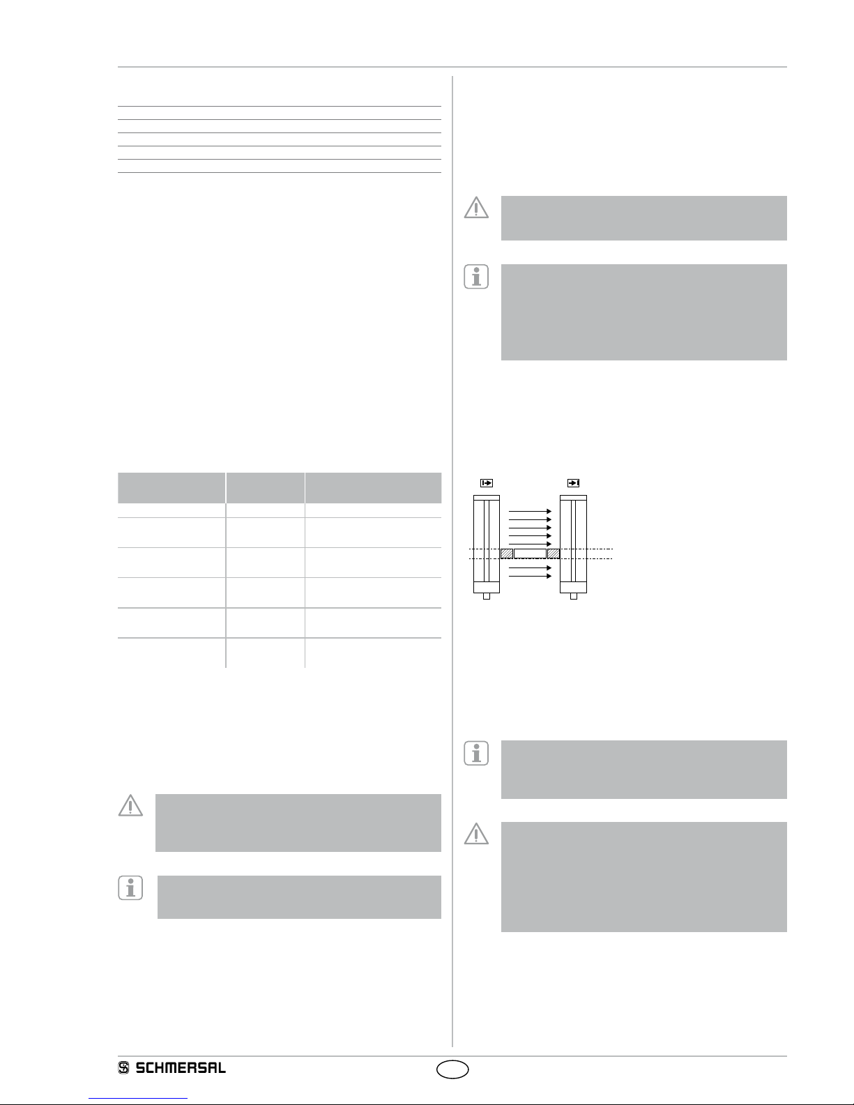
2.11 Beam coding A
The beam coding of the safety light curtain must be adjusted, when
systems operating in each other's vicinity and a set-up as shown in
the image below (no interference) is impossible. With beam coding
A, a receiver can distinguish the beams of the transmitter with the
same beam coding A, which are destined to this particular receiver,
from foreign beams. The beam coding A must be set for each sensor
(receiver and transmitter) individually. The function is activated by
means of the NSR-0801 BUS converter and a PC or laptop.
If adjacent systems are operated without beam coding A,
the user is at risk.
EERR
No interference
ERRE
Interference:
beam coding A required!
• The beam coding A avoids mutual interference of adjacent systems.
• The beam coding A is permanently shown by the transmitter and the
receiver by means of flashing LED's (refer to LED status information).
The response time of the system is increased when beam
coding A is used. To this end, the safety distance must be
adjusted to the hazardous movement. Refer to chapter
Response time.
3. Mounting
3.1 General conditions
The following guidelines are provided as a preventative warning notice
to ensure safe and appropriate handling. These guidelines are an
essential part of the safety instructions and therefore must always be
observed and respected.
• The SLC must not be used on machines, which can be
stopped electrically in case of emergency.
• The safety distance between the SLC and a hazardous
machine movement must always be observed and respected.
• Additional mechanical safety guards must be installed so that
the operator has to pass by the protection field to reach the
hazardous machine parts.
• The SLC must be installed so that the personnel always must
be within the detection zone when operating the machine. An
incorrect installation can lead to serious injuries.
• Never connect the outputs to +24VDC. If the outputs are
wired to +24VDC, they are in ON state, as a result of which
they are unable to stop a hazardous situation occurring on the
application/machine.
• The safety inspections must be conducted regularly.
• The SLC must not be exposed to inflammable or explosive
gasses.
• The connecting cables must be connected in accordance with
the installation instructions.
• The fixing screws of the end caps and the mounting angle
must be firmly tightened.
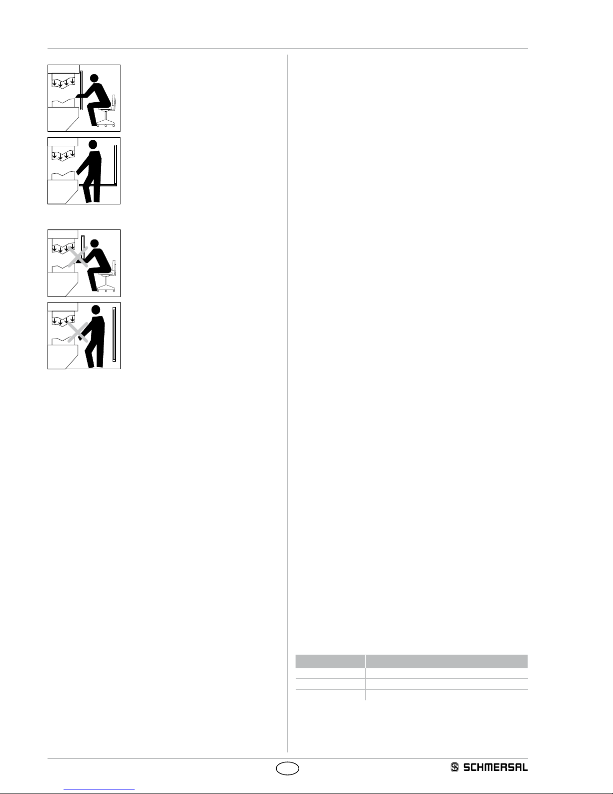
3.2 Protection field and approach
The protection field of the SLC consists of the entire range located
between the protection field markings of transmitter and receiver.
Additional protective devices must ensure that the operator has to pass
by the protection field to reach the hazardous machine parts.
The SLC must be installed so that personnel are always located within
the detection zone of the safety device when operating the hazardous
machine parts to be secure.
8
Operating instructions
Safety light curtain/safety light grid
SLC 420
SLG 420
EN
Correct installation
Hazardous machine parts can only be reached
after passing through the protection field.
Persons between the protection field and
hazardous machine parts must be prevented
(protection against stepping over).
Unauthorised installation
Hazardous machine parts can be reached
without passing through the protection field.
Persons between the protection field and
hazardous machine parts is enabled.
3.3 Alignment
Procedure in automatic operating mode:
1. The transmitter and the receiver must be fitted parallel to each other
and at the same height.
2. Turn the transmitter and monitor the diagnostic window of the
receiver. Fix the light curtain, when the LED OSSD ON (green) is on
and the LED signal reception (orange) is off.
3. Determine the max. rotating angle to the left and to the right, at which
the LED OSSD ON (green) is on and tighten the mounting screws in
central position. Make sure that the LED signal reception (orange) is
not on or flashing.
3.4 Setting mode
The alignment of the sensors is carried out using the setting mode.
Activating setting mode
If +24 V is on the input (pin 1, receiver) "Release restart interlock" at
system start for at least two seconds (by pressing the button restart),
the system changes over to the setting mode of operation.
The signal strength at the receiver is indicated with the signal strength
LED (colour orange) through light pulses. The better the alignment, the
higher the frequency of the light pulses. The alignment is optimal when
the light pulses switch over to continuous light.
If there is no optical synchronisation between the transmitter and the
receiver, a light pulse is emitted every 3 seconds. The setting mode is
ended by a system start ( +UB OFF/ON).
Additional signalling with the SLG 420 by the status light
In this mode the signal strength of the beam is signalled to the status
indicator with the lowest value through light pulses (colour yellow).
The better the alignment, the higher the frequency of the light
pulses. The alignment is correct when the light pulses switch over to
continuous light.
3.5 Safety distance
The safety distance is the minimum distance between the protection
field of the safety light curtain and the hazardous area. The safety
distance must be observed to ensure that the hazardous area cannot
be reached before the hazardous movement has come to standstill.
Calculation of the safety distance to EN ISO 13855
The safety distance depends on the following elements:
• Stopping time of the machine (calculation by run-on time
measurement)
• Response time of the machine and the safety light curtain and the
downstream relay (entire safety guard)
• Approach speed
• Resolution of the safety light curtain
• Vertical or horizontal installation
Safety light curtain SLC 420
The safety distance for resolutions 14 mm up to 40 mm (vertical
installation) is calculated by means of the following formula:
(1) S = K x T + C [mm]
S = Safety distance [mm]
K = Approach speed 2000 mm/s
T = Total reaction time (machine run-on time, reaction time of the safety
guard, relays, etc.)
d = Resolution of the safety light curtain
C = additional distance depending on the resolution,
C = 8 (d - 14) [mm]
If value S <= 500 mm after the calculation of the safety distance, then
use this value.
If the value S >= 500 mm then redetermine the distance S using an
approach speed K of 1600 mm/s:
(2) S = 1600 mm/s * T + 8 (d - 14) [mm]
If the new value S > 500 mm, use this value as safety distance.
If the new value S < 500 mm, use a minimum distance of S = 500 mm.
Example:
Reaction time of the safety light curtain = 10 ms
Resolution of the safety light curtain = 14 mm
Stopping time of the machine = 330 ms
S = 2000 mm/s * (330 ms + 10 ms) + 8(14 mm - 14 mm)
S = 680 mm
S = > 500 mm, therefore new calculation with K = 1600 mm/s
S = 544 mm
Calculation of the safety distance for SLG 420 and SLC 420 with a
resolution d > 40 mm
(3) S = ( 1600 mm/s * T ) + 850 mm
S = Safety distance [mm]
T = Stopping time of the machine + reaction time of the
safety light curtain
K = Approach speed 1600 mm/s
C = Additional distance 850 mm
The following mounting heights must be observed:
Number of beams Mounting height above reference level in mm
2 400, 900
3 300, 700, 1100
4 300, 600, 900.1200

9
SLC 420
SLG 420
Operating instructions
Safety light curtain/safety light grid
EN
Safety distance to the hazardous area
S
Hazardous
point
Transmitter
Receiver
Command device
Authorised operation
Mechanical protection
Direction from which
the hazardous area
is accessed
The safety distance between the safety light curtain and the
hazardous point must always be respected and observed. If
a person reaches the hazardous point before the hazardous
movement has come to a standstill, he or she is exposed to
serious injuries.
Safety distance to the hazardous area
Limit of the hazardous point
Safety distance (S)
Protection field
marking
Tool - upper part
Signal to stop the
hazardous movement
Standstill of the
hazardous movement
t
n
= tB - t
A
Tool - lower part
t
A
S
t
B
≤ 75 mm = max. distance for protection against stepping over
To prevent persons from stepping over the protection field this dimension must be
imperatively respected and observed.
The formulae and calculation examples are related to the vertical set-up
(refer to drawing) of the light curtain with regard to the hazardous point.
Please observe the applicable harmonised EN standards and possible
applicable national regulations.
To calculate the minimum distances of the safety guards with
regards to the hazardous point, the EN ISO 13855 must be
observed.
If reaching through the protection field is possible, take care
with the calculation of the safety distance and add an amount
as per norm EN ISO 13855.
The norm EN ISO 13855 defines two types of safety distances,
- Access through the protection area with an additional distance C,
according to the resolving power
- Access over the protection area with an additional distance CRO
according to table 1
If it is possible to reach through the hazardous area (vertical alignment)
then both values C and C
RO
have to be determined. The larger of the
two values is to be used for calculating the safety distance. Calculating
the safety distance with CRO:
S
CRO
= K x T + C
RO
K = Approach speed
T = Total reaction time (machine run-on time, reaction time of the safety
guard, relays, etc.)
CRO = Additional distance due to reaching through the hazardous area
with parts of body, see table 1 for value
1
2
3
KxT
S
RO
C
RO
a
b
1 Safety sensor
2 Hazardous point
3 Floor
a Height of the hazardous point
b Height of the topmost beam of the safety sensor

10
Operating instructions
Safety light curtain/safety light grid
SLC 420
SLG 420
EN
Reaching through the protective area of a non-contact functioning guard system (extract EN ISO 13855)
Height of the
hazardous point
a [mm]
Height b of the upper edge of the protection area of the non-contact functioning guard system
900 1000 1100 1200 1300 1400 1600 1800 2000 2200 2400 2600
Additional distance CRO to the hazardous area [mm]
2600 0 0 0 0 0 0 0 0 0 0 0 0
2500 400 400 350 300 300 300 300 300 250 150 100 0
2400 550 550 550 500 450 450 400 400 300 250 100 0
2200 800 750 750 700 650 650 600 550 400 250 0 0
2000 950 950 850 850 800 750 700 550 400 0 0 0
1800 1100 1100 950 950 850 800 750 550 0 0 0 0
1600 1150 1150 1100 1000 900 850 750 450 0 0 0 0
1400 1200 1200 1100 1000 900 850 650 0 0 0 0 0
1200 1200 1200 1100 1000 850 800 0 0 0 0 0 0
1000 1200 1150 1050 950 750 700 0 0 0 0 0 0
800 1150 1050 950 800 500 450 0 0 0 0 0 0
600 1050 950 750 550 0 0 0 0 0 0 0 0
400 900 700 0 0 0 0 0 0 0 0 0 0
200 600 0 0 0 0 0 0 0 0 0 0 0
0 0 0 0 0 0 0 0 0 0 0 0 0
Schedule 1
a = Height of the hazard spot [mm]
b = Height of the upper edge of the protection area of the AOPD
CRO = Additional distance to the hazardous area [mm]
Determination of the additional distance CRO from the table:
1) Locate the height of the upper edge of the hazardous area a (left table column)
2) Locate the height of the protection area b (upper table row)
3) CRO is to be taken from the crossing point of both exes
If the known value for a and b is between the table values, the next higher value is to be used.
11
SLC 420
SLG 420
Operating instructions
Safety light curtain/safety light grid
EN
Example: Calculation of the safety distance, vertical installation
Total response time T = 220 ms, resolving capability d = 30 mm, height
of the hazardous area 1400 mm, height of the protection area above
the floor 1600 mm
S = K * T + C = 2000 mm/s * 220 ms + 8 (30 -14) = 568 mm
(S > 500 mm, following K = 1600 mm/s)
S = K * T + C = 1600 mm/s * 220 ms + 8 (30 -14) = 480 mm
(S < 500 mm, following S = 500 mm) S = 500 mm
Safety distance C
RO
S
CRO
= K x T + CRO = 1600 mm/s x 220 ms + 650 mm = 1002 mm
S
CRO
> S i.e.
Safety distance S = 1002 mm
If the safety distance of 1002 mm is too large for the application, the
protection field height can be increased from 1600 mm to 1800 mm, this
makes the value CRO = 0 mm (table 1).
Result: By adjusting the protection field height to the value
1800 mm above the floor results in a safety distance: S = 500 mm
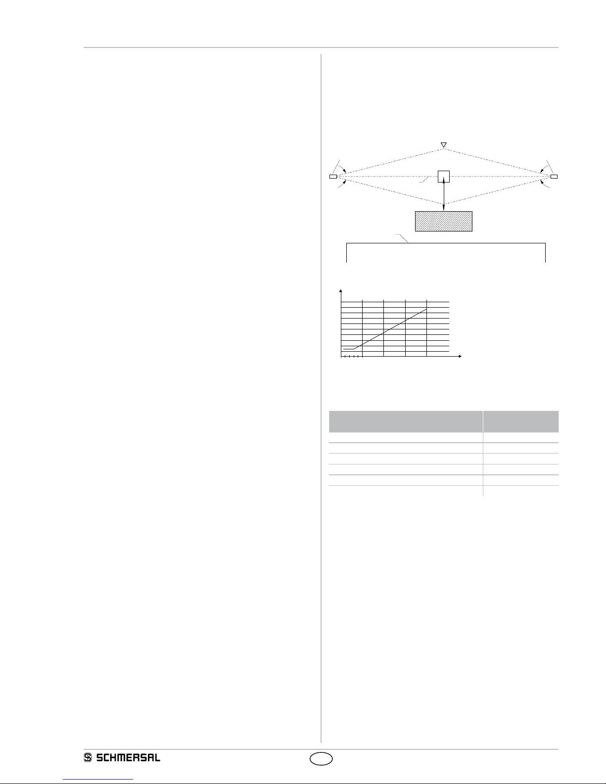
3.5.1 Minimum distance to reflecting surfaces
During the installation, the effects of reflecting surfaces must be taken
into account. In case of an incorrect installation, interruptions of the
protection field could possibly not be detected, which could lead to
serious injuries. The hereafter-specified minimum distances with regard
to reflecting surfaces (metal walls, floors, ceilings or parts) must be
imperatively observed.
8° 8°
a= 262 mm
Access direction
Receiver
Obstacle
Optical axis
Transmitter
Reflecting body
(e.g. Material container)
Limit of the
hazardous point
a=130mm
5° 5°
Safety distance a
a [mm]
D [m]
03510
100
200
300
400
500
600
700
800
900
1000
15 20
Calculate the minimum distance to reflecting surfaces as a function of
the distance with an aperture angles of ± 2.5° degrees or use the value
from the table below:
Distance between transmitter and receiver
[m]
Minimum distance a
[mm]
0.2 … 3.0 130
4 175
5 220
7 310
10 440
15 660
Formula: a = tan 2.5° x L [mm]
a = Minimum distance to reflecting surfaces
L = Distance between transmitter and receiver

12
Operating instructions
Safety light curtain/safety light grid
SLC 420
SLG 420
EN
3.6 Dimensions
3.6.1 Dimensions transmitter and receiver SLC 420 (Standard)
All measurements in mm.
49,6
48,7
42
31,5
6
80
86
A
B
C
Type A
Protected
height
B
Mounting
dimension
C
Total
lenght
SLC420-E/R0170-XX-RFB 170 288 324
SLC420-E/R0250-XX-RFB 250 368 404
SLC420-E/R0330-XX-RFB 330 448 484
SLC420-E/R0410-XX-RFB 410 528 564
SLC420-E/R0490-XX-RFB 490 608 644
SLC420-E/R0570-XX-RFB 570 688 724
SLC420-E/R0650-XX-RFB 650 768 804
SLC420-E/R0730-XX-RFB 730 848 884
SLC420-E/R0810-XX-RFB 810 928 964
SLC420-E/R0890-XX-RFB 890 1008 1044
SLC420-E/R0970-XX-RFB 970 1088 1124
SLC420-E/R1050-XX-RFB 1050 1168 1204
SLC420-E/R1130-XX-RFB 1130 1248 1284
SLC420-E/R1210-XX-RFB 1210 1328 1364
SLC420-E/R1290-XX-RFB 1290 1408 1444
SLC420-E/R1370-XX-RFB 1370 1488 1524
SLC420-E/R1450-XX-RFB 1450 1568 1604
SLC420-E/R1530-XX-RFB 1530 1648 1684
SLC420-E/R1610-XX-RFB 1610 1728 1764
SLC420-E/R1690-XX-RFB 1690 1808 1844
SLC420-E/R1770-XX-RFB 1770 1888 1924
3.6.2 Dimensions transmitter and receiver SLG 420 (Standard)
All measurements in mm.
L2
42
L1
51
B
C
31;5
A
97
86
49,6
48,7
6
80
Type A
Beam
distance
B
Mounting
dimension
C
Total
lenght
L1 L2
SLG420-E/R0500-02-RF 500 648 684 349 303
SLG420-E/R0800-03-RF 400 948 984 249 203
SLG420-E/R0900-04-RF 300 1088 1124 209 203
L1 = Mounting distance (mm) between floor and slotted hole centre
(short end cap)
L2 = Mounting distance (mm) between floor and slotted hole centre
(diagnostic window)

13
SLC 420
SLG 420
Operating instructions
Safety light curtain/safety light grid
EN
3.6.3 Dimensions transmitter and receiver SLC 420 IP69K
All measurements in mm.
60
B
80
A
C
D
42
91
54
Type A
Protec-
ted
height
B
Sensor
length
C
Mounting
dimension
D
Total
length
SLC420-E/R0170-xx-69-RFB 170 267 315 351
SLC420-E/R0250-xx-69-RFB 250 347 395 431
SLC420-E/R0330-xx-69-RFB 330 427 475 511
SLC420-E/R0410-xx-69-RFB 410 507 555 591
SLC420-E/R0490-xx-69-RFB 490 587 635 671
SLC420-E/R0570-xx-69-RFB 570 667 715 751
SLC420-E/R0650-xx-69-RFB 650 747 795 831
SLC420-E/R0730-xx-69-RFB 730 827 875 911
SLC420-E/R0810-xx-69-RFB 810 907 955 991
SLC420-E/R0890-xx-69-RFB 890 987 1035 1071
SLC420-E/R0970-xx-69-RFB 970 1067 1115 1151
SLC420-E/R1050-xx-69-RFB 1050 1147 1195 1231
SLC420-E/R1130-xx-69-RFB 1130 1227 1275 1311
SLC420-E/R1210-xx-69-RFB 1210 1307 1355 1391
SLC420-E/R1290-xx-69-RFB 1290 1387 1435 1471
SLC420-E/R1370-xx-69-RFB 1370 1467 1515 1551
SLC420-E/R1450-xx-69-RFB 1450 1547 1595 1631
3.6.4 Dimensions transmitter and receiver SLG 420 IP69K
All measurements in mm.
80
104
A
C
D
B
60
42
A1
Type A
Beam
dis-
tance
A1
Beam
posi-
tion
B
Sen-
sor
length
C
Mounting
dimensi-
on
D
Total
length
SLG420-E/R0500-02-69-RF 500 71 627 675 711
SLG420-E/R0800-03-69-RF 400 71 927 975 1011
SLG420-E/R0900-04-69-RF 300 111 1067 1115 1151

14
Operating instructions
Safety light curtain/safety light grid
SLC 420
SLG 420
EN
3.7 Scope of delivery and accessories
3.7.1 Included in delivery
Test rod PLS
The test rod, according to the resolution is used for testing the
protection field.
Mounting kit MS-1030 (SLC/SLG 420 Standard)
The mounting kit consists of 4 steel angles and 16 fixing screws.
14,5
42
18,9
20
6,5
40
32
52
Mounting kit MS-1038 (SLC/SLG 420 IP69K)
The mounting kit consists of 4 pcs V4A stainless steel brackets
and 16 pcs V4A fastening screws
14,5
42
18,9
20
6,5
40
32
52
21
¤5,5
Integrated status indication (only SLG 420)
The status indication at the receiver indicates the switching condition of
the outputs OSSD1 and OSSD2.
Green = Outputs in ON state (H-signal 24V)
Red = Outputs in OFF state (L-signal 0V)
Yellow = Restart Interlock released / Setting mode
18
30
¤
20
3.7.2 Optional accessories
Centre fixing MS-1051
Mounting kit consists of 2 steel angles, 4 screws and 4 T-slot nuts for
central fixing
40
42
20
14,5 18,9
32
20
38
Connecting cable for transmitter
Item Number Designation Description Length
1207741 KA-0804 Female connector M12,
4-pole
5 m
1207742 KA-0805 Female connector M12,
4-pole
10 m
1207743 KA-0808 Female connector M12,
4-pole
20 m
Connecting cable for Receiver
Item Number Designation Description Length
1207728 KA-0904 Female connector M12,
8-pole
5 m
1207729 KA-0905 Female connector M12,
8-pole
10 m
1207730 KA-0908 Female connector M12,
8-pole
20 m
BUS converter NSR-0801
Converter for parameterisation and diagnostics. Detailled information
can be found in the operating instructions manual of the NSR-0801.
Included in delivery: integrated connecting cable, PC-software USB 2.0
connection (L x W x H, 122 x 60 x 35 mm), dimensions exclude cable.
MSD4 Vibration damper
Kit consisting of: 8 vibration dampers 15 x 20 mm, 8 cylinder head
screws M5 with hexagon socket, 8 spring washers
The MSD4 vibration damper kit is recommend to be used for damping
vibrations and oscillations (such as presses and stamps) on the
SLC/SLG. In this way, the availability of the SLC/SLG is increased.
15
SLC 420
SLG 420
Operating instructions
Safety light curtain/safety light grid
EN
4. Electrical connection
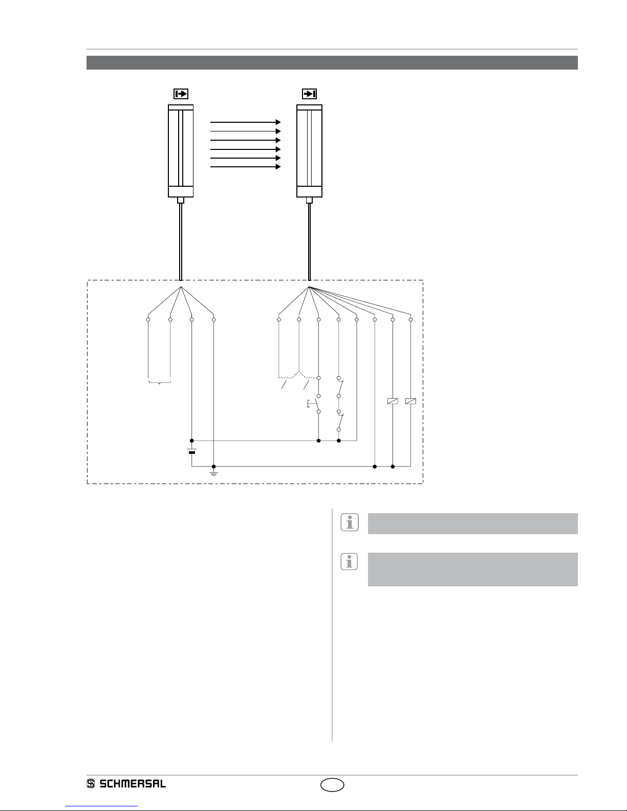
4.1 Wiring example default
5
Kn 1
Kn 2
S 1
K1 K2
6
1
8
2
7
3
4
Schützkontrolle/EDM(RD)
DIAG IN (WH)
DIAG IN (GY)
DIAG OUT (PK)
Freigabe WA (WH)
DIAG OUT (BK)
0 V DC (BU)
0 V DC (BU)
OSSD 1 (GN)
OSSD 2 (YE)
+24 V DC (BN)
+24 V DC (BN)
Brücke 1
Brücke 2
Erdung
E1
Nur für Diagnose
1
2
3
4
DIAG IN (WH)
DIAG OUT (BK)
Only for Diagnostic
DIAG IN (GY)
Bridge 1
DIAG OUT (PK)
+24 VDC (BN)
0 VDC (BU)
Release/restart
interlock (WH)
Bridge 2
+24 VDC (BN)
Contactor control/EDM (RD)
OSSD 2 (YE)
OSSD 1 (GN)
0 VDC (BU)
Earth connection
Restart interlock (manual reset) (bridge 1)
By bridging DIAG IN (pin 5) and DIAG OUT (pin 6), the restart interlock
(manual reset) is activated.
Protective mode (bridge 2)
By bridging DIAG OUT (pin 6) and enable (pin 1), the automatic
protective mode is activated. Do not connect S1.
K1, K2: Relay for processing the switching outputs
OSSD 1,OSSD 2
Kn1, Kn2: Auxiliary contacts of the last switching relay (optional)
signals at input EDM (pin 8): only to be connected when
the function is activated
S1: Command device for restart (optional)
E1: Power supply 24 VDC +/-10%
For proper functioning, the operating mode restart interlock
or operating mode automatic is to be wired.
Upon delivery, the "contactor control" function is deactivated.
The function is activated by means of the NSR0801 BUS
converter and the PC software.

16
Operating instructions
Safety light curtain/safety light grid
SLC 420
SLG 420
EN
4.2 Activation of the contactor control (EDM) without PC software
The contactor control can be activated without PC software as of
firmware version 2.0 in diagnostic mode by means of cable bridges.
To activate the EDM function without PC software, proceed in the
following way:
Establish the connections in accordance with the wiring diagram,
see below.
Both outputs OSSD1 and OSSD2 of the light curtain must be
separated from the machine control.
S1
E1
24VDC
27
13
4
The parameter configuration EDM is activated for at least 2 seconds
when the system starts if there is a wire link between OSSD 1 ➔ OSSD2
and a +24V level on the input restart interlock.
The active operating mode parameterisation is signalled by the cyclical
changing of the red, yellow and green LEDs until the restart interlock
button is no longer being pressed.
The parameterisation can now be made by pressing the button.
• If the red and greed LEDs flash at the same time, this indicates that
the EDM function is active, if only the red LED flashes then the EDM
function is not active.
• Holding down the button from 2.5 to 6 seconds changes the state of
the EDM function between active and not active and saves the current
selection.
After the parameterisation, the link OSSD1 ➔ OSSD2 is to be removed
and a system start is to be carried out (+ 24V, OFF/ON). If the EDM
function is parameterised with the wire link, the max. value of 500 ms is
set for the signal delay. This value can be adjusted using the PC software
/ NSR-0801.
If the parameterisation is missing the process can be repeated.
4.3 Connector configuration Receiver, Transmitter & Cable
RECEIVER
SLC: Connector
male M12 / 8 pol.
Signal
Designation Description
5
8
4
3
2
1
7
6
1 WH Restart Input
2 BN 24 VDC Power supply
3 GN OSSD 1 Safety output 1
4 YE OSSD 2 Safety output 2
5 GY Diagnostic IN Input diagnostic data
6 PK Diagnostic OUT Output Diagnostic data
7 BU 0 VDC Power supply
8 RD Contactor
control EDM
Input
Cable: Connector
female M12 / 8 pole
5
8
4
3
2
1
7
6
TRANSMITTER
SLC: Connector
male M12 / 4 pol.
Signal
Designation Description
3
2
1
4
1 BN 24 VDC Power supply
2 WH Diagnostic IN Input diagnostic data
3 BU 0 VDC Power supply
4 BK Diagnostic OUT Output Diagnostic data
Cable: Connector
female M12 / 4 pole
3
2
1
4
The colour codes are only valid for the cable types
mentioned below "optional accessories".

17
SLC 420
SLG 420
Operating instructions
Safety light curtain/safety light grid
EN
5. Set-up and maintenance
5.1 Check before start-up
Prior to start-up, the following items must be checked by the
responsible person.
Wiring check prior to start-up
1. If a power supply is used then it must comply with IEC 60449 PELV
and should be able to bridge a loss of power for at least 20 ms as
per EN 60204.
2. Presence of a voltage supply with correct polarity at the SLC.
3. The connecting cable of the transmitter is correctly connected to the
transmitter and the connecting cable of the receiver correctly to the
receiver.
4. The double insulation between the light curtain output and an
external potential is guaranteed.
5. The outputs OSSD1 and OSSD2 are not connected to +24 VDC.
6. The connected switching elements are not connected to the +24
VDC and do not exceed the allowable load on the safety output.
There are no short circuits between the safety switching outputs.
7. If two or more SLC are used within close range compared to each
other, an alternating arrangement must be observed. Any mutual
interference of the systems must be prevented.
Switch the SLC on and check the operation in the following way:
The component performs a system test during approx. 2 seconds after
the operating voltage has been switched on. After that, the outputs are
enabled if the protection field is not interrupted. The LED "OSSD ON"
at the receiver is on.
In case of incorrect functionality, please follow the instructions
listed in the chapter Fault diagnostic.
5.2 Maintenance
Do not use the SLC before the next inspection is
terminated. An incorrect inspection can lead to serious
and mortal injuries.
Conditions
For safety reasons, all inspection results must be archived. The
operating principle of the SLC and the machine must be known in order
to be able to conduct an inspection. If the fitter, the planning technician
and the operator are different persons, please make sure that the user
has the necessary information at his disposal to be able conduct the
maintenance.
5.3 Regular check
A regular visual inspection and functional test, including the following
steps, is recommended:
1. The component does not have any visible damages.
2. The optics cover is not scratched or soiled.
3. Hazardous machinery parts can only be accessed by passing
through the protection field of the SLC.
4. The staff remains within the detection area, when works are
conducted on hazardous machinery parts.
5. The safety distance of the application exceeds the mathematically
calculated one.
Operate the machine and check whether the hazardous movement
stops under the hereafter-mentioned circumstances.
6. Hazardous machine parts do not move when the protection field is
interrupted.
7. The hazardous machine movement is immediately stopped, when
the protection field is interrupted with the test rod immediately before
the transmitter, immediately before the receiver and in the middle
between the transmitter and the receiver.
8. No hazardous machine movement when the test rod is within the
protection field.
9. The hazardous machine movement comes to standstill, when the
voltage supply of the SLC is switched off.
5.4 Half-yearly inspection
The following items must be checked every six months or when a
machine setting is changed.
1. Machine stops or does not inhibit any safety function.
2. No machine modification or connection change, which affects the
safety system, has taken place.
3. The outputs of the SLC are correctly connected to the machine.
4. The total response time of the machine does not exceed the
response time calculated during the first putting into operation.
5. The cables, the connectors, the caps and the mounting angles are in
perfect condition.
5.5 Cleaning
If the optics cover of the sensors is extremely soiled, the OSSD outputs
can be disabled. Clean with a clean, soft cloth with low pressure.
The use of agressive, abrasive or scratching cleaning agents, which
could attack the surface, is prohibited.
18
Operating instructions
Safety light curtain/safety light grid
SLC 420
SLG 420
EN
6. Diagnostic
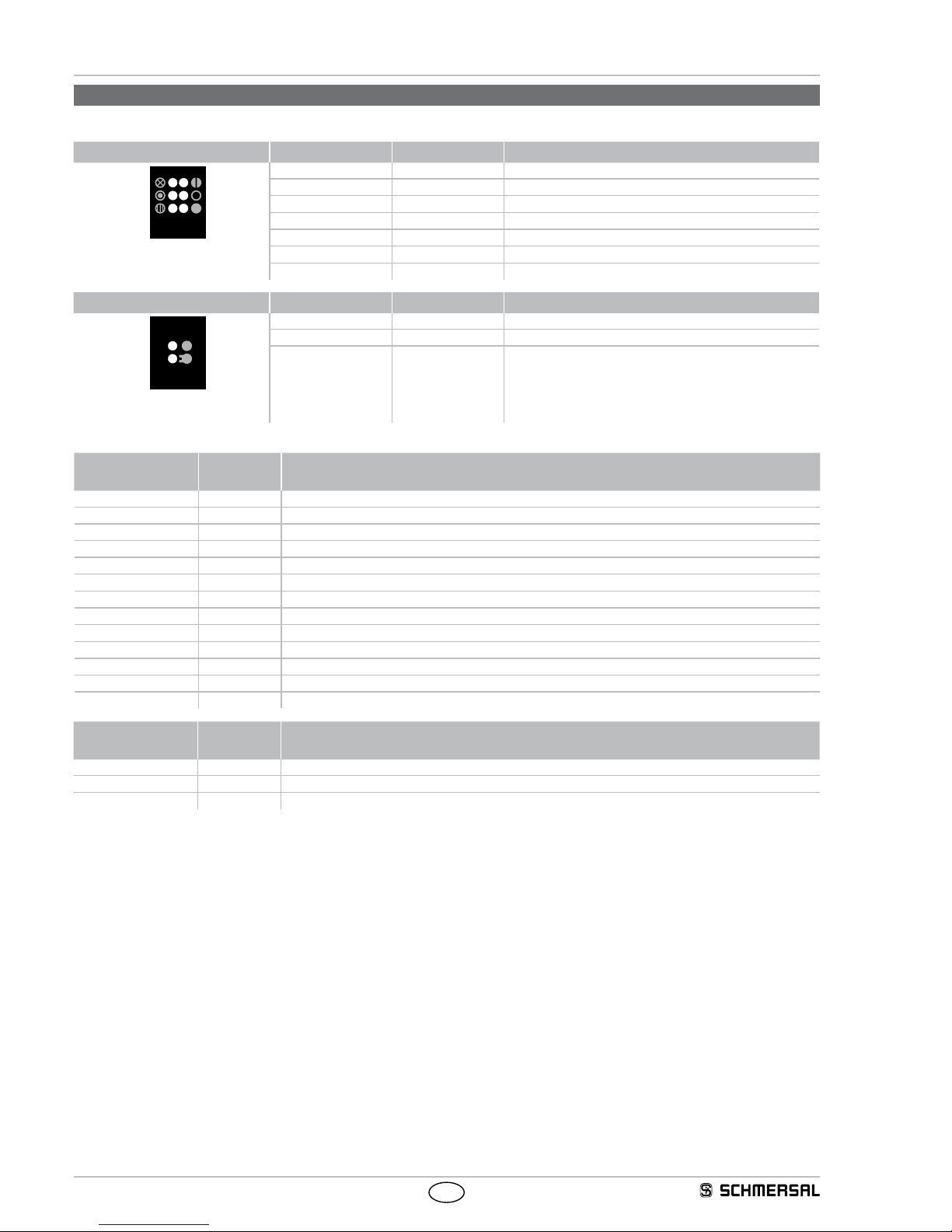
6.1 LED status information
Receiver Function LED colour Description
Multifunction
Blanking
Signal reception
Restart
OSSD OFF
OSSD ON
Protection
field
Multifunction yellow-green Function display, Beam coding
Blanking blue Protection field(s) inactive (blanking)
Signal reception orange Evaluation of the signal reception, signal quality set-up mode
Restart yellow Input for command device, AOPD is waiting for enable signal
OSSD OFF red Safety switching output in OFF state
OSSD ON green Safety switching output in ON state
Transmitter Function LED colour Description
Transmitting
Protection
field
Status
Transmitting orange Transmitter active
Status green Function display, Beam coding
Receiver
LED Status LED Description
OSSD ON On Protection field clear
flashing Diagnostic mode active
OSSD OFF On Safety switching output in OFF state
flashing Diagnostic mode active, error output refer to Fault diagnostic table
Restart On Start or restart interlock (manual reset) active, signal expected at input restart interlock
Signal reception ON/flashing Signal reception too low, check alignment and installation height between transmitter and receiver
Cleaning the black profile cover, set-up mode - signal state indicator
Blanking 1 flash Fixed blanking of the protection field(s)
2 flash Floating blanking, max. 1 beam
3 flash Floating blanking, more beams
4 flash Floating (max. 1 beam) and fixed blanking of protection field(s)
5 flash Variable (multiple beams) and fixed blanking of protection field(s)
Multifunction flashing Beam coding A is active
Transmitter
LED Status LED Description
Transmitting On Standard operation, transmitter active
flashing Configuration error
Status flashing Beam coding A is active

19
SLC 420
SLG 420
Operating instructions
Safety light curtain/safety light grid
EN
6.3 Extended diagnostic
By means of the optional SLC 420 configuration software and the
NSR-0801 BUS converter, an extended diagnostic can be executed.
The software provides the status information of the component and can
represent the individual light beams. This feature enables an optimal
adjustment of the light curtain. The diagnostic mode is signalled by
the OSSD ON and OSSD OFF LED‘s at the receiver. In diagnostic
mode, protective mode is disabled, the ODDS outputs being locked.
The change from diagnostic mode to protective mode is automatically
realised after voltage reset, when the BUS converter is no longer
integrated and the connecting cable of the sensor is reconnected.
7. Disassembly and disposal
7.1 Disassembly
The safety switchgear must be disassembled in a de-energised
condition only.
7.2 Disposal
The safety switchgear must be disposed of in an appropriate manner in
accordance with the national prescriptions and legislations.
8. Appendix
8.1 Contact
Consultancy / Sales:
K.A. Schmersal GmbH & Co. KG
Möddinghofe 30
D-42279 Wuppertal
Tel:+49 (0) 202 64 74 -0
Fax:+49 (0) 202 64 74- 100
You will also find detailed information regarding our product variety on
our website: www. schmersal.com
Repair handling / shipping:
Safety Control GmbH
Am Industriepark 2a
D-84453 Mühldorf / Inn
Tel.: +49 (0) 8631-18796-0
Fax: +49 (0) 8631-18796-1
6.2 Fault diagnostic
After the operating voltage for the light barrier has been switched on, the safety-monitoring module performs an internal self-test. When a fault is
detected, a corresponding flashing pattern is emitted at the receiver through the LED OSSD OFF (red). Each fault display is followed by a onesecond delay.
LED OSSD OFF Fault feature Action
Red and yellow LEDs
flash together
Wiring error for function selection
(restart interlock, automatic mode)
Check connection at the receiver, bridge 1 or bridge 2 must be wired
(refer to Wiring)
1 x flash Wiring fault Bridge operating mode, check wiring and signal level
2 x flashes Fault with the external power supply UB = 24V / DC ± 10%, power source and primary voltage check.
A system reset is performed after three error indications.
3 x flashes Error input contactor control Check connection at contactor control input, check short-circuit
to +UB and 0V. Check function status
4 x flashes Errors at the OSSD outputs Check the connections of both outputs, short-circuit of both OSSDs,
connection to signal level 0V or 24V, deactivate cross-wire short
monitoring downstream of the system inputs
5 x flashes Error configuration data Check and save the parameter setting with the BUS converter
NSR-0801
6 x flashes Error blanking Check the blanked area(s) with the selected parameterisation,
repeat the configuration in the parameter setting (PC software)
and adapt if necessary
7 flashes Other errors, diagnostic Restart the system, exchange components if there is a
permanent fault diagnosis

20
EN
SLC/SLG420-B-EN
Operating instructions
Safety light curtain/safety light grid
SLC 420
SLG 420
9. EU Declaration of conformity
K. A. Schmersal GmbH & Co. KG
Möddinghofe 30, D - 42279 Wuppertal
Postfach 24 02 63, D - 42232 Wuppertal
Phone: +49 - (0)2 02 - 64 74 - 0
Telefax: +49 - (0)2 02 - 64 74 - 1 00
E-Mail: info@schmersal.com
Internet: http://www.schmersal.com
Place and date of issue: Mühldorf, September 15, 2016
Authorised signature
Klaus Schuster
Managing Director
Authorised signature
Christian Spranger
Managing Director
EU Declaration of conformity
Original Safety Control GmbH
Am Industriepark 2a
84453 Mühldorf / Inn
Germany
We hereby certify that the hereafter described components both in their basic design and construction conform
to the applicable European Directives.
Name of the component: SLC 420 / SLG 420
SLC 420 IP69K / SLG 420 IP69K
Type: See ordering code
Description of the component: Safety light curtain / safety light grid
Relevant Directives: Machinery Directive
EMC-Directive
RoHS-Directive
2006/42/EC
2014/30/EU
2011/65/EU
Applied standards: EN 61496-1:2013,
EN 61496-2:2013,
EN ISO 13849-1:2008 + AC:2009
EN 62061:2005 + A1:2013
Notied body for the prototype test: TÜV Nord Cert GmbH
Langemarckstr. 20, 45141 Essen
ID n°: 0044
EC-prototype test certicate: No. 440205013144611
Person authorized for the compilation
of the technical documentation:
Oliver Wacker
Möddinghofe 30
42279 Wuppertal
The currently valid declaration of conformity can be
downloaded from the internet at www.schmersal.net.
 Loading...