


Operating instructions
Multifunctional safety controller
Operating instructions. . . . . . . . . . . .pages 1 to 20
EN
Original
PROTECT SELECT
PROTECT SELECT OEM
Content
1 About this document
1.1 Function ..............................................2
1.2 Target group: authorised qualied personnel..................2
1.3 Explanation of the symbols used ...........................2
1.4 Appropriate use ........................................2
1.5 General safety instructions ...............................2
1.6 Warning about misuse ...................................2
1.7 Exclusion of liability .....................................2
2 Product description
2.1 Ordering code .........................................2
2.2 Special versions........................................2
2.3 Destination and use .....................................2
2.4 Technical data .........................................3
2.5 Safety classication .....................................4
3 Mounting
3.1 General mounting instructions .............................4
3.2 Disassembly...........................................4
3.3 Disposal ..............................................4
4 Electrical connection
4.1 General information for electrical connection..................4
4.2 Power supply ..........................................4
4.3 Start level.............................................4
4.4 Sensor level ...........................................4
4.5 Actuator level ..........................................5
5 Operating principle and settings
5.1 Connection / operating elements ...........................6
5.2 Description of the terminals ...............................6
5.3 Start level.............................................6
5.4 Sensor level ...........................................6
5.5 Actuator level ..........................................7
5.6 Project planning ........................................7
5.7 Conguration ..........................................7
6 Set-up and maintenance
6.1 Operating the safety module ..............................9
6.2 Putting into operation for the rst time .......................9
6.3 Conguration ..........................................9
6.4 Behaviour in the case of faults.............................9
6.5 Maintenance .........................................10
7 Menu structure
7.1 Menu structure - Safety module...........................10
8 Appendix
8.1 Application programs ...................................11
8.2 Error message, warning and status indication................19
9 EU Declaration of conformity
x.000 / 04.2016 / v.A. - 101218873-EN / H / 2016-04-27 / AE-Nr. 6010
EN
1

Operating instructions
Multifunctional safety controller
PROTECT SELECT
PROTECT SELECT OEM
1. About this document
1.1 Function
This operating instructions manual provides all the information you
need for the mounting, set-up and commissioning to ensure the safe
operation and disassembly of the safety-monitoring module. The
operating instructions must be available in a legible condition and a
complete version in the vicinity of the device.
This document constitutes operating instructions within the meaning of
the Machine Directive 2006/42/EC Annex I, Article 1.7.4.
1.2 Target group: authorised qualified personnel
All operations described in this operating instructions manual must
be carried out by trained specialist personnel, authorised by the plant
operator only.
Only install and commission the device once you have read and
understood these instructions and are acquainted with the applicable
regulations on machine safety and accident prevention. The selection
and installation of the devices and the technical incorporation into the
control system require qualified knowledge of the pertinent laws and
requirements set out in standards.
1.3 Explanation of the symbols used
Information, hint, note:
This symbol is used for identifying useful additional information.
Caution: Failure to comply with this warning notice could
lead to failures or malfunctions.
Warning: Failure to comply with this warning notice could
lead to physical injury and/or damage to the machine.
1.7 Exclusion of liability
We shall accept no liability for damages and malfunctions resulting from
defective mounting or failure to comply with the operating instructions
manual. The manufacturer shall accept no liability for damages resulting from the use of unauthorised spare parts or accessories.
For safety reasons, invasive work on the device as well as arbitrary repairs, conversions and modifications to the device are strictly forbidden;
the manufacturer shall accept no liability for damages resulting from
such invasive work, arbitrary repairs, conversions and/or modifications
to the device.
2. Product description
2.1 Ordering code
This operating instructions manual applies to the following types:
Standard-version: PROTECT SELECT
OEM-version: PROTECT SELECT OEM
2.2 Special versions
For special versions, which are not listed in the order code below 2.1,
these specifications apply accordingly, provided that they correspond to
the standard version. For special versions, the supplementary operating
instructions are to be observed.
2.3 Destination and use
The safety module for integration in safety circuits is designed to fit in
control cabinets.
The safety module is for the safe evaluation of potential-free and OSSD
type sensors safety control equipment and safe analogue signals.
1.4 Appropriate use
The product described here has been developed to assume safetyoriented functions as part of an overall system or machine.
The safe state corresponds to the de-energised state.
It is the responsibility of the manufacturer of a machine or plant to
ensure the correct functionality of the entire machine or plant. The
safety-monitoring module must be exclusively used in accordance
with the versions listed below or for the applications authorised by the
manufacturer. Detailed information regarding the range of applications
can be found in the chapter 2.
1.5 General safety instructions
The user must observe the safety instructions in this operating
instructions manual, the country-specific installation standards as well
as all prevailing safety regulations and accident prevention rules.
Further technical information can be found in the Schmersal
catalogues or in the online catalogue on the Internet:
www.schmersal.net.
There are no residual risks, provided that the safety instructions as well
as the instructions regarding mounting, commissioning, operation and
maintenance are observed.
All information without guarantee. Subject to change.
1.6 Warning about misuse
If used incorrectly or not for the intended purpose or in the
case of tampering, danger to persons or damage to machine
and system parts from using the safety module cannot be
ruled out.
The logical switching of the inputs to the outputs is determined by a
pre-programmed application program. To be able to adapt to each of
the application uses the application program has adjustable parameters. Setting the parameters is done using the safety module with a
rocker switch in conjunction with a colour display.
The safety function is the safe shutdown of the safety outputs (Q0 to Q3
and QR1 to QR2) upon request via the safety inputs (I00 to I17 and AI0
to AI1) and in the event of a fault. In the switched off state the outputs
have no power this means that relay output contacts are open and
semiconductor outputs are non-conducting.
To determine the Performance Level (PL) of the entire safety function
(e.g. sensor, logic, actuator) to DIN EN ISO 13 849-1, an analysis of all
relevant components is required.
The safety-relevant current paths with the outputs Q0 to Q3 meet the
following requirements under observation of a B10d value assessment
(also refer to chapter 2.5 "Safety classification"):
– Category 4 – PL e to DIN EN ISO 13849-1
– corresponds to SIL CL 3 to DIN EN 62061
The entire concept of the control system, in which the safety
component is integrated, must be validated to the relevant
standards.
If the monitoring of an Emergency-Stop command device
is not implemented using the safety module PROTECT SELECT the monitoring must take place using another suitable
manner.
2
EN

Operating instructions
Multifunctional safety controller
PROTECT SELECT
PROTECT SELECT OEM
2.4 Technical data
General data
Standards: EN 60204-1 ; EN 60947-5-1; EN 62061;
ISO 13849-1; IEC 61508
Mounting: snaps onto standard DIN rail to EN 60715
Dimensions (W/H/D): 52.5 x 100 x 118 mm
Weight: 300 g
Readiness after switching on: approx. 6 s
Mechanical data
Terminal types: Spring force terminals or screw terminals
Cable section: 0.25...2.5 mm²
Connecting cable: rigid or flexible (including conductor ferrules)
Mechanical life: 107 operations
Electrical life: Derating curve available on request
Resistance to shock: to IEC 60068-2-29
Resistance to vibrations: to IEC 60068-2-6
Ambient conditions
Ambient temperature: −25 °C … +55 °C,
no condensation;
with vertical installed position
Storage and transport temperature: −25 °C … +75 °C,
no condensation
Climatic conditions: Humidity 15 % … 90 %,
no condensation
Protection class: IP20
Installation compartment: earthed, lockable switch cabinet
with class of protection IP54
Air clearances and creepage distances: EN 50178 (double insulation)
EMC rating: EN 61000-6-2; EN 61496-1;
EN 62061; IEC 61326-3-1
EMC interference radiation: EN 61000-6-4
Overvoltage category: III
Degree of pollution: 2
Electrical data
Rated operating voltage: 24 VDC +/− 10%
Fuse rating: 3 A slow blow external
Power consumption at 24 VDC: max. 500 mA, internally
fused plus load current
Safe digital inputs
Number: 18 single channel / up to 9 dual channel inputs
Voltage / current: 24 V; 6 mA
Level (nominal):
- Low: −3 V … 2.0 V
- High: 18 V … 28.8 V
Category / PL / SIL CL:
- Single channel, with minimum
Request interval = 30 h: Cat. 2 / PL d / SIL CL 2
- Dual channel: Cat. 4 / PL e / SIL CL 3
Safe analogue inputs
Number: 2
Measuring range voltage: 0 … 10 V
Voltage change: Sinusoidal: max. 2.8 Hz; max. 25 V/s
Measuring range current:
- with external shunt resistor: 0 … 20 mA
- 500 Ω / 0.5W / < 1%: 4 … 20 mA
Current change: Sinusoidal: max. 2.8 Hz; max. 50 mA/s
Input resistance: 10 kΩ
Safe analogue inputs
Category / PL / SIL CL:
- Single channel (If a cable break dominates): Cat. 3 / PL d / SIL CL 2
- Dual channel: Cat. 4 / PL e / SIL CL 3
Accuracy: 3%
Resolution: 12 Bit
Safe semi-conductor outputs
Number (p-/n-switching): 2
- Note: with OEM -version an activation of the second
p+n-switching output Q1/Q1N is possible.
In this case a derating must be observed.
Number (p switching): 2
Max. current at 24V: 0.7 A / output, resistive load,
short-circuit proof
Output teat pulse: type 0.5 ms; max. 2 ms,
with a capacitive load
Category / PL / SIL CL:
- Single channel, with minimum
Request interval = 47min: Cat. 2 / PL d / SIL CL 2
- Dual channel: Cat. 4 / PL e / SIL CL 3
Reaction times:
- Digital inputs: Switching off: < 30 ms
Switching on: < 45 ms
- Analogue inputs: Switching off: < 100 ms
Switching on: < 120 ms
- Note: The stable time must be added to the specified ON times.
Voltage drop:
- Residual current: < 1 V, < 2 mA
- Leakage current in the case of error: < 1 mA
Minimum operating current: > 5 mA
Required short-circuit current: 9 A
Safe relay outputs
Number: 2 (common access)
Contact load capacity (B
- AC1: 250 V / 4 A
- AC15: 230 V / 3 A
- DC 1: 24 V / 4 A
- DC 13: 24 V / 4 A / 0.1 Hz
Category / PL / SIL CL:
- Single channel: Cat. 1 / PL c / SIL CL 1
- Dual channel: Cat. 4 / PL e / SIL CL 3
Residual current at 24V: 4 A
Fuse rating: 4A gL/gG (for residual current)
Reaction times:
- Digital inputs: Switching off: < 50 ms
- Analogue inputs: Switching off: < 120 ms
- Note: The stable time must be added to the specified ON times.
Required short-circuit current: 1000 A to EN 60947-5-1
Rated isolated voltage: to EN 50178, double insulation
Signalling outputs
Number, optional: 4
Max. current at24V: 0.1 A, resistive load,
Test pulse outputs
Number: 3
Max. current at24V: 0.1 A, resistive load,
Switch-off test pulse: <1.5 ms
cULus LISTED 382E
Main supply: 24 V, Class 2
Consumption: 2.6 A
Ambient temperature: + 55°C
Semiconductor output current: sum 2.1 A
Relay output: C300, R300
values see below):
10d
Switching on: < 65 ms
Switching on: < 140 ms
conditionally short-circuit proof
conditionally short-circuit proof
EN
3

Operating instructions
MT
Bdxxhs/h3600
0,1 x n
op
t
cycle
Multifunctional safety controller
PROTECT SELECT
PROTECT SELECT OEM
2.5 Safety classification
Standards: EN ISO 13849-1; IEC 62061;
EN 60947-5-1; IEC 61508
PL: up to e
Control category: up to 4
DC: medium
CCF: > 65 points
SIL CL: up to 3
SFF: > 90 %
PFHd to IEC 61508: 1.78 x 10⁻⁸ 1/h
- Note: Valid for dual channel and 60% relay load.
Service life: 20 years
Hardware fault tolerance: 1
Mode of operation: High demand / continuous
MTTF
d (inputs+logic)
MTTF
d (semi-conductor outputs)
B
value (for one channel of the relay output): Low load range 20%:
10d
TF
d
For an average annual demand rate of nop = 126,720 cycles per year,
Performance Level PL e can be obtained at maximum load.
nop = average number of activations per year
d
= average number of operating days per year
op
hop = average number of operating hours per day
t
= typical demand of the safety function in s
cycle
(e.g. 4 × per hour = 1 × per 15 min. = 900 s)
(Specifications can vary depending on the application-specific
parameters hop, dop and t
The MTTFd value results as follows
Semi-conductor output: 1/MTTF
Relay output: 1/MTTF
: >100 years
: >100 years
10,000,000
40%: 7,500,000
60%: 2,500,000
80%: 1,000,000
Maximum load 100%: 400,000
10d op op
n
op
as well as the load.)
cycle
d(inputs+logic)
d(inputs+logic)
+ 1/MTTF
+ 1/MTTF
d(semi-conductor outputs)
d(relay)
4. Electrical connection
4.1 General information for electrical connection
The electrical connection may only be carried out by
authorised personnel in a de-energised condition!
4.2 Power supply
A1: 24 VDC ± 10% (via external safety fuse 3 A slow blow)
A2: GND, this must be connected to the protective earth (PE).
FE: Functional earth (short line where possible min. 1.5 mm²)
Requirements placed on the power supply unit
- Safety mains transformer in accordance with
DIN EN 61558 / VDE 0570 Part 2-6
- Switching power supply unit in accordance with
DIN EN 60950-1 and DIN EN 50178. The power supply
unit must be suitable to supply SELV current circuits in
accordance with DIN EN 60950-1.
The FE connection (functional ground) must be
connected to PE.
If A2 and PE do not have a connection, FE must be
connected to A2.
4.3 Start level
Number and terminal will depend on the application program
(see chapter 8.1).
4.4 Sensor level
Number and terminal will depend on the application program
(see chapter 8.1). All inputs are plus-switching.
Input circuits which have been deactivated via the parameter
assignment may not be connected.
3. Mounting
The safety module should only be installed and removed
when without power.
3.1 General mounting instructions
Snap the bottom of the enclosure slightly tilted backwards in the
DIN rail and push down until it latches in position.
Depending on requirements, the connectors can be coded
individually using the supplied coded pins.
Electrical power cables must be routed separately from
communication lines.
3.2 Disassembly
Unlock the bottom of the enclosure by means of a slotted screwdriver,
push up and hang out slightly tilted forwards.
3.3 Disposal
After the maximum service life of 20 years, the security module should
be disposed of properly in accordance with national laws and regulations.
2-channel potentialfree with cross-wire
monitoring
T0 T1
I00I01
2-channel potentialfree with NO and
NC contacts
T0 T1
I00I01
2--channel potentialfree without cross-wire
monitoring
24 VDC
I00I01
Safety mat
(4-wire)
T0 T1
I00I01
2-channel electronic
output (cross-wire
monitoring via sensor)
24 VDC
I00I01
1-channel potentialfree connection
first contact
T0 T1
I00I01
4
EN

Operating instructions
Multifunctional safety controller
PROTECT SELECT
PROTECT SELECT OEM
Proximity switches with Reed contacts (e.g. safety switches
such as the Schmersal BNS type series) may not be
connected to inputs (I0, I4, I12, I14) due to the alternative
function as signalling output. They must satisfy the following
technical requirements
– switching capacity: min. 240 mW
– switching voltage: min. 24 VDC
– switching current: min. 10 mA
When a safety mat is connected make sure that the clock
outputs are decoupled, for example via diodes.
When installing the cables the safe analogue inputs
AI0 / AI1 high frequency signal decoupling must be avoided.
Recommended cable type for the safe analogue inputs AI0 /
AI1: LAPP KABEL unitronic® FD CP (TP) plus 1 x 2 x 0.75
For inputs that are configured for antivalent (1NO/1NC)
evaluation, the NO contact must always be connected to the
input with the odd number.
With single-channel use the input with the odd number is
not used.
Test pulses
The correct function of the semi-conductor outputs is secured by a
cyclical test, i.e. all switched outputs are deactivated for approx. 0.5 ms
(in the event of capacitive loads the deactivation is for a maximum of 2
ms).
If contactors and coils are connected suitable protective
measures (free-wheeling diode, varistor or similar) must be
taken to protect the internal output switching.
If after a shutdown of max. 2 ms no HIGH signal is detected
on the semiconductor output (e.g. due to a capacitive load),
a system failure is the result.
If a subsequent assembly is disturbed by the test pulse
it can be eliminated by including a D/C filter in the circuit:
Typical values: 3…10 kΩ, 1000 nF
10…30 kΩ, 330 nF
The resulting signal delay is to be considered.
Signalling outputs
The terminals I0/Y0, I4/Y1, I12/Y2 and I14/Y3 may be used both as
safe input and as signalling output.
Which function is used will depend on the application program
(see chapter 8.1).
The signalling outputs Y0…Y3 are not safety-related.
When connecting safety door interlocks the door position
should be connected to the even input and magnet position
connected to the odd input.
4.5 Actuator level
2 x safe p-/n-switching semiconductor outputs (Q0/Q0N, Q1/Q1N)
with 24 VDC
2 x safe p-switching semiconductor outputs (Q2, Q3) with 24 VDC
2 x safe relay outputs (QR1, QR2) with common supply (QR0)
up to 250 VAC or 24 VDC
4 x operational optional message outputs (Y0 … Y 3) with 24 VDC
Relay outputs
250 V / 24 V
QR 1
QR 2
Semi-conductor
outputs
*1
Q0
K1
K2
GND GND
*1
QR 2
K1 K2
K1
Q1
*1
250 V / 24 V
QR 0
QR 1QR2
K2
QR 1QR2
K1 K2
GND GND
Q2 Q3
K1 K2
Q0N
*1 Measures for short circuit shutout against the supply are necessary
Q1 N
GND GND
EN
5
Operating instructions
Multifunctional safety controller
PROTECT SELECT
PROTECT SELECT OEM
5. Operating principle and settings
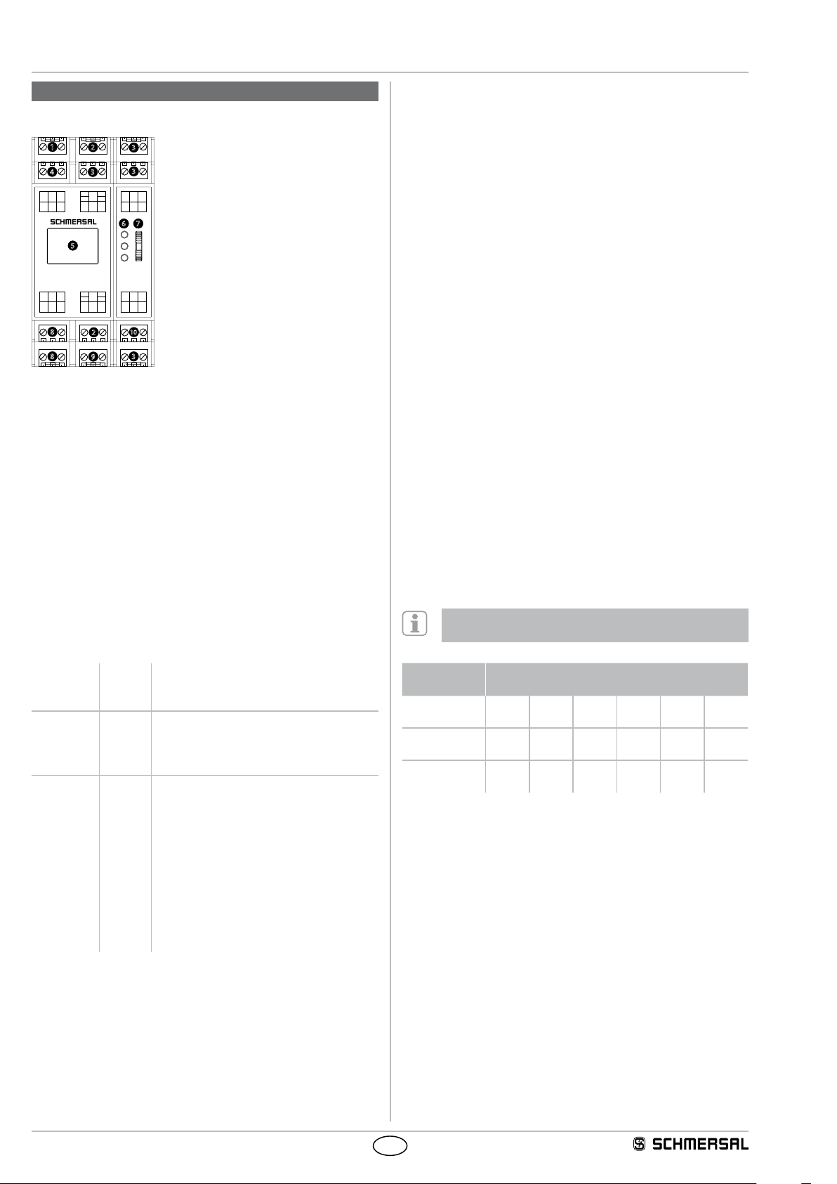
5.1 Connection / operating elements
1 Cycle outputs T0...T2
2
1
4
T1 T2
T0
A1
A2 FE
Q0 Q3 Q1N
Q0N
Q2 Q1
8
8
5
PROTECT
I0
Y0
I1
I12
Y2
3
3
3
I4
I2
I6 I8 I10
Y1
I7
I9 I11
I3
I5
6 7
2 Safe inputs /
optional signalling outputs
3 Safe inputs
4 Supply voltage
5 Graphic colour display
6 Status LEDs
7 Rocker switch
8 Safe semi-conductor outputs
U
B
Run
ERR
I14
I13
AI0
AGND
AI1
Y3
QR0QR2QR1
I15
I16I17
10
2
3
9
9 Safe relay outputs
10 Safe analog inputs
Operating the rocker switch
Up/down: Navigation through the menu and the input masks.
Press: Acceptance of the entry or confirmation of an action.
LED indications
UB lights up operating voltage applied
Run lights up operating mode
blinking Configuration mode or module has the factory
defaults (see initial parameterization)
ERR illuminates A fault is present (safe condition)
blinking There is a caution or warning
(Operation with possible limitations)
Fault / Warnings / Messages appear on the display in plain text.
Menu structure
The complete structure may be derived from Chapter 7.
5.2 Description of the terminals
5.3 Start level
Alternatively: auto-start or manual start (falling edge)
Optional: feedback circuit (EDM), start-up testing
Start-up test
After switching on the supply voltage again the protective device must
first be opened and closed again before the enable can be activated
with the start/RESET button.
5.4 Sensor level
18 safe digital inputs
Selectable: 1-channel of 2-channel, equivalent,
antivalent or deactivated.
Optional condition: Short circuit recognition,
discrepancy monitoring
2 safe analogue inputs
2 analogue safe 1-channel inputs each with 4 adjustable limit values
or 1 analogue safe 2-channel input with 4 adjustable limit values and
adjustable monitoring of the percentage (of maximum value = 4095)
channel deviation.
Discrepancy monitoring
After a request for a 2-channel protection device that is carried out by
only one of the input channels, both input channels must be opened
and closed again before the release with the START / RESET button
can be activated.
Cross-wire detection
Measure for detecting short circuits between the input channels for
2-channel operation. The cross-circuit detection is achieved here by
the use of clock outputs T0 ... T2 using floating safety sensors. The
assignment of the clock outputs to the inputs is fixed. The setting takes
place in the inputs menu.
To reach cat. 4 / PL e / SIL CL 3, cross-circuit detection
must be enabled in floating safety sensors.
Voltage A1
A2
FE
Inputs I0...I17
AI0
AI1
AGND
Outputs Q0, Q0N
Q1, Q1N
Q2
Q3
QR0
QR1
QR2
Y0...Y3
T0...T2
+24 VDC
0 VDC
functional earth connection
Safe digital inputs
Safe analogue input
Safe analogue input
Analogue ground
Safe semi-conductor output p-/n-switching
Safe semiconductor output p-/n-switching
(only available OEM-products)
Safe semi-conductor output p-switching
Safe semi-conductor output p-switching
Supply of safe relay output
Safe relay outputs
Safe relay outputs
Operational outputs (signalling output)
Clock outputs for the supply of safe digital
inputs for short-circuit recognition
Cycle outputs Digital inputs I00 … I17
(optional signalling outputs Y0 … Y3)
T0 closed I00
(Y0)
T1 closed I01 I04
I03 I06 I09 I12
(Y2)
I07 I10 I13 I16
(Y1)
T2 closed I02 I05 I08 I11 I14
(Y3)
Analogue limit values
The limit values are set with a number of between 0 to 4095.
The following conversion applies:
Limit value = Voltage [V] x 337
I15
I17
6
EN

Operating instructions
Multifunctional safety controller
PROTECT SELECT
PROTECT SELECT OEM
5.5 Actuator level
The actuator level consists of:
2x p-/n-switching safe outputs
2x p-switching safe outputs
2x safe relay outputs
4x optional signalling outputs
Each safe output can be switched off either without delay (Stop 0) or
delayed (Stop 1) via safe timer.
5.6 Project planning
The planner selects the suitable application program and stipulates the
necessary parameter assignment data. All information must be entered
by setting instructions for the person charged with commissioning. The
person charged with commissioning transfers this data to the safety
module, verifies the correct parameter assignment and wiring. The
following sequence must be observed for planning:
1. Definition of the safety function and determination of the
requisite PL / Cat. / SIL.
2. Selection of the suitable application program.
3. Assignment of the periphery to the terminals.
4. Stipulation of the necessary additional functions.
5. Stipulation of which inputs require cross-wire detection.
6. Analogue inputs: stipulation of the type and limit values.
If not used, lay AI0+AI1 to AGND and values to 4095.
7. Setting wiring plan.
8. Determination of the MSP code (see chapter 5.7).
9. Entry of the MSP code and additional functions in the
setting instructions.
10. Entry of the cross short settings in the setting instructions.
11. Entry of the requisite timer values.
12. Entry of the analogue settings.
13. Enter the desired PIN.
The following PINs are not allowed:
- 0000, 0001, 0815, 4711
- 1111, 2222, 3333, 4444, 5555, 6666, 7777, 8888, 9999
- 0123, 1234, 2345, 3456, 4567, 5678, 6789
- 9876, 8765, 7654, 6543, 5432, 4321, 3210
14. Sign setting instructions.
5.7 Configuration
Multifunctional sensor processor (MSP)
An input circle is analysed using a multifunctional sensor processor
MSP) which is parameter-assigned by a three-digit hexadecimal
number. The 1. position describes the sensor, the 2. position the
additional function and the 3. position the contact properties.
The entry of the MSP code is from right to left.
MSP
code
0 Sensor evaluation
1 Emergency stop
2 Safety switch
3 Interlock (electro-
4 Electronic solenoid
5 Non contact safety
6 Safety mat (4-wire)
7 AOPD e.g. SLC220
Sensor type
(1st position)
deactivated
command device
(contact) e.g. AZ16
mechanical, magnetic
and actuator switch)
e.g. AZM161
interlocks
e.g. AZM200,
AZM300, MZM100
switch e.g. BNS 260
e.g. SMS5
Electronic safety
sensors e.g. RSS36,
CSS sensors
Feature
- There is no evaluation of a connected sensor!
- Upon detection of a signal, an
error message is generated on
the screen!
- Upon detection of a signal, all
safety outputs are disabled!
Evaluation of the internal clock signals of the clock outputs T0 to T2
Setting = Cross-wire short
Evaluation of the internal clock signals of the clock outputs T0 to T2
Setting = Cross-wire short
- Direct activation of the interlock
(power supply for the magnet)
over the semiconductor outputs
Q0 / Q0N
- Evaluation of the internal clock
signals of the clock outputs T0
to T2
- Setting = Cross-wire short
- No simultaneous evaluation
of the solenoid and actuator
contacts
- The monitoring time is automatically set to infinity
- Direct activation of the interlock
(power supply for the magnet)
over the semiconductor outputs
Q0 / Q0N
- Evaluating signals of the safety
sensors
- No evaluation of the internal
clock signals of the clock outputs
T0 to T2
- Setting = Standard
- Simultaneous evaluation of the
solenoid and actuator contacts
- Evaluation of the internal clock
signals of the clock outputs T0
to T2
- Setting = Cross-wire short
- Evaluation of the internal clock
signals of the clock outputs T0
to T2
- Setting = Safety mat
- Evaluating signals of the safety
sensors
- No evaluation of the internal
clock signals of the clock outputs
T0 to T2
- Setting = Standard
- Test pulses by the sensor can be
tolerated
EN
7

Operating instructions
Multifunctional safety controller
PROTECT SELECT
PROTECT SELECT OEM
Additional functions (2nd Stelle)
MSP
Discrepancy error
code
0
1
2
3
4
5
6
7
8
9
A
B
C
D
E
F
Contact properties (3rd Stelle)
0 Equivalent (e.g. 2 NC contacts) Standard setting
1 Antivalent (e.g. 1 NC contact, 1 NO contact)
2 Single
Example, MSP code:
Emergency stop command device with active discrepancy monitoring,
feedback loop and 2 NC contacts.
MSP 0 A 1 = E-stop command device
monitoring
•
• •
• •
• • •
• •
• • •
• • •
• • • •
(e.g. 1 NC contact)
channel
3. position
If the additional function "Discrepancy monitoring" is not used
in a two-channel sensor, this should be especially justified in
the risk analysis.
Start-up test Feedback
•
• •
• •
• • •
2. position
1. position
circuit
Autostart
•
•
• •
Input sequence
from right to left
The interlock type always applies to all connected guard
interlocks.
Analog inputs
Dual Sensor 2-channel analysis of AI0 and AI1 with percentage
tolerance between the two channels.
Single sensor Single channel analysis of AI0 and AI1.
In addition to the input type, 4 limit values can be set for every input (if
“Dual Sensor“ is selected for both).
Inputs
Standard (S) No cross-wire detection for input active.
Cross-wire short (C) Cross-circuit detection for this input is active.
Safety mat (M) Connecting a 4-wire safety mat. Cross-circuit
detection for this input is active.
Times
Each MSP has a safety switch device input filter for bounce on
protective equipment, or detection of failures.
Monitoring time / discrepancy time
Maximum tolerated delay between the channels of a 2-channel input. If
exceeded a warning on the screen is displayed and the indicator light
Y3 flashes. Both channels must be opened to clear before the input can
be activated again. Unless otherwise specified, this time is set to 10s
(guard interlocks set to infinity).
Stable time
During the stable time (default value = 0.1 s) there is a debounce time,
which causes a turn-on delay. The release of the safety function only
takes place when both input contacts are switched stable for the
duration of the stabilizing time.
Operating situation
Input K1
Input K2
monitoring time
Door interlocking mechanisms have an infinite discrepancy,
this allows the additional function to be used for error
detection.
With an activated discrepancy monitoring the interlock has
to be opened after an unlocking request.
Kontakteigenschaft (3. position) = single-channel: The
input with the even number is always evaluated (e.g. sensor
on I02 and I03 the input I02 single-channel is evaluated).
The odd input must remain open.
Sensor type 0 (deactivate): With a HIGH signal to the
sensor inputs of a disabled sensor all safety clearances
are deactivated.
On deactivation of auto-start the function of monitored
start is selected.
Further Parameter
Interlock type
Power to unlock For spring-locked guard interlocks.
Power to lock For solenoid-locked guard interlocks.
Stable time
Authorised operation
Error
Fault situation
Input K1
Input K2
monitoring time
Stable time
Authorised operation
Error
The setting for the monitoring time / discrepancy time
and stable time must be greater than zero.
8
EN

Operating instructions
Multifunctional safety controller
PROTECT SELECT
PROTECT SELECT OEM
6. Set-up and maintenance
The person putting into operation for the first time makes the necessary
settings on the safety module using the setting instructions and then
verifies these. The following sequence is to be observed.
1. Make settings in accordance with the setting instructions.
2. Compare the read-back displays with the setting instructions.
3. Enter the parameter program CRC in the setting instructions.
4. Perform acceptance check (checking of function, correct wiring,
polarity of the actors, …. ).
5. Sign setting instructions and minutes of the acceptance check.
6. Add setting instructions and minutes of the acceptance check to the
machine documentation.
6.1 Operating the safety module
The safety module is operated using the rocker switch. If an entry us
emphasised by a coloured bar (cursor), the menu can be navigated
by moving the switch up and down. The current entry is selected by
pressing on it. If this is a parameter, the value can now be set (”up/
down“). The value is similarly accepted by pressing the rocker switch.
If you actuate “up” the first time you enter a menu, you will reach the
higher ranking menu. If the screen saver appears (a moving circle), this
is similarly left by pressing the rocker switch. The term ENTER used in
the further description for pressing the rocker switch.
6.2 Putting into operation for the first time
1. After switching on the start screen appears.
2. The request is then made to select the menu
language (default: English).
3. The necessity for a configuration / parameter
setting is displayed after ENTER.
4. Confirm by ENTER.
5. To conduct the configuration a PIN must be entered (factory default: 0000). The entry is made
SCHMERSAL
PROTECT
SELECT
Language
English
CAUTION!
Module needs to be
configured first!
Enter PIN
0000
number by number using the rocker switch (up/
down). The next number is reached by ENTER.
6. After correct entry the “Safety module configuration“ screen appears.
Configuration
Safety module
10. Now set the requisite values for the analogue
inputs and times.
11. Once all settings have been made leave the
menu by moving "Up" until the query "Save Yes/
No" appears. Confirm with "Yes". All parameters
Parameter
Analog inputs
Inputs
Times
Save Config?
YES
NO
are then shown on several screen pages (red
background). All parameters are marked with
"M" (modified). Check all values once more and
scroll further with "ENTER".
12. After display of “Readback completed“ you will
reach the PIN entry.
13. First enter the factory set PIN 0000.
14. Then you must enter and repeat the new PIN
from the settings instructions.
15. The CRC which is now shown must be entered
in the settings instructions.
Enter PIN
0000
Enter new PIN
3107
New CRC
Par-CRC: A5778EDB
Write down CRC!
Press button to
restart...
6.3 Configuration
The setting is made essentially as described in chapter 5.7.
Alternatively:
If the logo appears after switching on, the display of the set program
is first reached by pressing the rocker switch and then the main menu.
If no logo appears, but an SPS message, moving “Up” until you reach
the main menu. Select “Configuration“ here. The PIN to be entered is
now the one on the settings instructions. The sequence corresponds to
than of “Putting into operation for the first time”. For the final parameter
display with red background only altered values marked with a blue “M“
are shown and must be checked specially.
LED RUN
lights up: operating mode
blinking: Configuration mode or module has the factory
defaults (see initial parameterization)
7. Enter the menu by ENTER. Now select the
desired program and confirm with ENTER.
8. The list of the MSP codes now appears for the
input circuits. Set the corresponding code for
every MSP in accordance with the list. After
entry a plain text display of the selected settings
appears. ENTER moves back to the code list
display. If you navigate “up“ with the last MSP
code, the next menu appears.
9. If a guard lock is used the selection of the type
will appear (Power to unlock: Yes/no).
Program select
Prog 01
Prog 02
Prog 03
Prog 04
Input circuit code
MSP 01: 1 A 5
MSP 02: 3 6 8
MSP 03: 6 D 2
1 E 7
MSP 03: (1 E 7)
E-Stop 2K
NC/NC start
Feedback circuit
Start-up + Cycl. Test
Solenoid interlock
Power to unlock
6.4 Behaviour in the case of faults
In the event of a fault the following procedure is recommended
1. UB LED dark: Check voltage supply
2. ERR LED lights up/flashes: Analyse error message on the display
and arrange for appropriate actions.
3. ERR LED dark: Fault cannot be diagnosed by PROTECT SELECT.
Action: Check the external cabling
LED ERR
illuminated: There is a fault (safe condition)
blinking: There is a caution or warning
(Operation with possible limitations)
Fault/Warnings/Messages appear on the display in plain text.
EN
9

Operating instructions
Multifunctional safety controller
PROTECT SELECT
PROTECT SELECT OEM
6.5 Maintenance
A regular visual inspection and functional test, including the following
steps, is recommended:
1. Check the correct fixing of the safety module
2. Check the cable and device for damage/manipulation indications
3. Check electrical function
If relay outputs are used:
• For PLd (Cat 3) / SIL 2 (with HFT 1) at least every 12 months
or
• for PLe (Cat 3 or 4) / SIL 3 (with HFT 1) at least once a month.
Otherwise: at least once every 12 months.
Damaged or defective components must be replaced.
7. Menu structure
7.1 Menu structure - Safety module
Status
Safety module
Inputs
Display of status of the inputs.
Outputs
Display of status oft he outputs.
Analogue AI0
Display of the current analogue values and status
of the set limit values.
Analogue AI1
Display of the current analogue values and status
of the set limit values.
System
Operating duration
Display of the time at which the system was activated.
Warnings
If the ERR display flashes the warnings can
be shown here.
History
Display of the last changes of the inputs/outputs.
Error message
If the rocker switch is pressed in this menu,
a new start is possible.
Error code
Internal error code
Error message
Plain text message of the error code
Troubleshooting
Description of possible error cause and rectification measures
Restart
Trigger of a new start once the error has been eliminated.
Configuration
Enter PIN
Entry of the PIN codes so as be able to perform the
configuration.
Program select
Selection of one of the application programs. With the
SELECT version there is a description of the programs in
chapter 8. In the OEM version the customer-specific
documentation must be consulted.
Input circuits
Parameter assignment of the MSP in accordance
with chapter 5.7.
Solenoid interlocks
Selection of the guard interlock type (see chapter 5.7):
power to lock or power to unlock principle
If the configuration is left without saving the
old state remains valid.
Parameter
Analog inputs
Input type
Single sensor: Single channel
Dual sensor: Dual channel with
specification of the
tolerance of the channels.
Limit values
Limit values of the analogue inputs.
Inputs
Standard (S) 24 VDC for ON
Cross-wire short (C) Cycle signal for ON.
(see chapter 5.4)
Safety mat (M) For safety mats in
short circuit mode.
Times
Setting of the timer.
Adjustment
Contrast
Stipulation of the contrast.
Screen saver
Waiting time until the screen saver becomes active.
Language
Setting of the language.
Info
Firmware version
Specification of the firmware version used.
Hardware info
Identification of the hardware.
Program version
Specification of the program including the hash totals (CRC)
for program and parameter assignment.
Configuration
Display of the current configuration.
10
EN

Operating instructions
Multifunctional safety controller
PROTECT SELECT
PROTECT SELECT OEM
8. Appendix
8.1 Application programs
General
The safety enable can only be given if all activated input circuits are
closed and the analogue input values are below the limit values.
The programs listed here are valid only for the standard
variant PROTECT SELECT and version 2.0 of the application
program (printed safety seal "Appl V2.0").
If the CRC of the following application programs described in
this document deviates from the indicated product program
CRC then the following information in this operating manual
does not apply.
When using the START/RESET button, requirements of the
DIN EN ISO 13849-1:2008, Chapter 5.2.2. (manual reset)
must be considered.
With a parameter setting of "Emergency-Stop":
The START/RESET button (I15) must be activated at all
events after "Power On".
If no feedback circuit (EDM) is evaluated, then the
corresponding input to 24VDC must be set to ensure the
safety function of the activated / deactivated safe analogue
inputs.
During the sequence of the after travel time (STOP 1)
the actuation of all START/RESET buttons is ignored.
In case of a voltage drop or a system failure, the device
shut off immediately without delay.
Sensor level: Safe digital inputs
In the following application programs, there is the possibility for the
specified free sensors to include the following safety switching devices:
• Emergency stop command devices, electronic and safety switches
with contacts, safety interlocks, proximity sensors, AOPDs, muting
sensors and 4-wire safety mats.
According to EN 60204-1:2006, a manual reset is necessary
after triggering the emergency stop. If the emergency stop
is configured with the option auto-start, a manual reset must
be realised by other suitable measures.
Sensor level: Safe analogue inputs
Implemented in the following application programs for both analogue
secure inputs are the following functions, coupled to the 4 limit values:
1. Limit (AI0-0 and AI1-0): Additional release interlock
2. Limit (AI0-1 and AI1-1): No function implemented
3. Limit (AI0-2 and AI1-2): No function implemented
4. Limit (AI0-3 and AI1-3): Emergency Stop
Description:
• Additional release for the interlock:
If an interlock is parameterized and the two analogue input values are
below the first limit (AI0-0 and 0-AI1) and are among the remaining
limits, then the locking unit of the connected interlock can be unlocked.
• Emergency-Stop-Function:
If one of the analogue input values is above the fourth limit (AI0-3 or
AI1-3) then this corresponds to the triggering of the Emergency Stop.
Connect the non-required analogue inputs to AGND and
set the corresponding analogue limit values to 4095.
In the application programs, the error case of a wire break
in the analogue input is not controlled.
If it is necessary to control such the analogue input may
be used with the “Dual Sensor“ option.
Sensors and emergency stop command devices can be
reset in any order.
Actuator level
The actuator level for the subsequent application programs consists of:
1x p-/n-switching safe output Q0 / Q0N
2x p-switching safe outputs Q2 and Q3
2x Safe relay outputs QR1 and QR2
4x optional signalling outputs Y0 up to Y3
The number of shutdown paths depends on the application program
selected:
• There are a maximum of five shutdown paths available.
• Every safe shutdown path can have an individual shutdown delay
(Stop 1) assigned.
• The default times are set to 0.00 s, this means that the safe shutdown
paths are shutdown without delay (Stop 0).
The output times are allocated to the following timers:
Output Timer Designation Behaviour Default
Q0/Q0N T00 TOF 0 delayed OFF 0.00s
The number of free sensors depends on the program.
If all sensors have the auto-start option in a protective area,
then a START/RESET button for this protective area is not
necessary.
Sensors and emergency stop command devices can be
reset in any order.
Q2 T02 TOF 2 delayed OFF 0.00s
Q3 T03 TOF 3 delayed OFF 0.00s
QR1 T04 TOF 4 delayed OFF 0.00s
QR2 T05 TOF 5 delayed OFF 0.00s
Y2 T06 TON 1 delayed ON 0.00s
Timer T00 up to T29: 0…599.99 s Step: 10 ms
Timer T31 and 32: 0…59999 s (ca. 16.6 h) Step: 1 s
EN
11

Operating instructions
Multifunctional safety controller
PROTECT SELECT
PROTECT SELECT OEM
DESCRIPTION:
TOF: Timer, shutdown delay
TON: Timer, switch on delay
With the setting: Safety door
If an "interlock" selection is active, the output Q0/Q0N does
not behave like a safety release, because it is used to control
the solenoid
Safety interlocks, 2-channel floating:
with solenoid and interlock monitoring and direct control of the interlock
unit (magnet)
Power to unlock Power to lock
T2
Q0 Q0NA2A1
I02
T2
I02
A1Q0 A2 Q0N
Application program 01
Prog_01: A safety area, visible from control area,
enabling switches + operating mode selector switch,
4 x individual sensors,
1 x Emergency-Stop command device (variable sensors)
(CRC 9FB6)
Connection example
Terminal assignment of the digital inputs
I00 + I01 Operating mode selector switch
automatic: I00 = HIGH & I01 = LOW
manual: I00 = LOW & I01 = HIGH
I02 + I03 Enabling switches MSP 6 (Default value=0 0 0)
I04 + I05 1. sensor: MSP 2 (Default value=0 0 0)
I06 + I07 2. sensor: MSP 3 (Default value=0 0 0)
I08 + I09 3. sensor: MSP 4 (Default value=0 0 0)
I10 + I11 4. sensor: MSP 5 (Default value=0 0 0)
I12 Unlock solenoid interlock
I13 Feedback circuit
I14 --I15 START / RESET or latch
interlock
I16 + I17 Emergency stop
command device,
for I16 + I17 and
for I04 up to I11
MSP 1 (Default value=0 A 1)
T0
Interlock:
With electromechanical solenoid interlocks the magnet
contact must be open. With a purely electronic solenoid
interlock both inputs must have a LOW signal.
When using an electro-mechanical solenoid interlock the
contact for the actuator must always be wired to the even
input and the contact for the magnets on the odd input!
I03
T0
I03
Terminal assignment of the outputs
Q0, Q0N Stop 0 or Stop 1 with fail-safe timer T00
Option with selection "Latch": working or quiescent current
Q2 Stop 0 or Stop 1 with fail-safe timer T01
Q3 Stop 0 or Stop 1 with fail-safe timer T02
QR1 Stop 0 or Stop 1 with fail-safe timer T03
QR2 Stop 0 or Stop 1 with fail-safe timer T04
Terminal assignment of the signalling outputs
(optionally digital input)
Y0 (I00) --Y1 (I04) --Y2 (I12) --Y3 (I14) Signalling output: error message / status indication:
Manual mode: Flashing with 2Hz
Warning: Flashing with 1Hz
Error messages: Lights up
Program description
The application program is based on a monitored visible safety area.
There is only a general requirement that lock and unlock all controlled
interlocks.
The user has the option of connecting 4 individual sensors to the inputs
I04 to I11.
12
EN

Operating instructions
Multifunctional safety controller
PROTECT SELECT
PROTECT SELECT OEM
In addition, the inputs can be changed as individual sensors I16 and I17
together with the default setting "Emergency Stop command device".
This sensor evaluation for the inputs I16 and I17 have a higher priority
and will not be bridged by the "operation mode selector switch +
enabling device".
Via the inputs I00 and I01 an operating mode selector switch is evaluated.
The selection of the operating mode selector switch is as follows:
- Automatic mode: I00 = HIGH and I01 = LOW
- Manual mode: I00 = LOW and I01 = HIGH
When the operating mode selector switch is set to "manual mode",
the sensors can be bridged via the inputs I04 to I11 in their safety
monitoring via an enabling switch to the inputs I02 and I03.
The condition START / RESET via the input I15 is permanently
assigned to the inputs I16 + I17 and I04 to I11
The connected sensors I04 to I11 switch off the outputs Q0/Q0N,
Q2 and Q3, QR1 and QR2.
Digital inputs I12, I13, I15
• Input I12 (unlock interlock: " Open door request"):
Request to unlock the guard interlock so that the safety area can be
accessed.
• Input I13 (feedback circuit):
Feedback circuit from the actuators (e.g. guards, drive regulator,
inverter, valve terminal etc.) is switched as an additional condition to
the function macro.
• Input I15 (RESET for the Emergency-Stop command device and for
the sensors I04 to I11):
- Restart condition after the Emergency-Stop control device has been
actuated.
- Restart condition of the safety sensors, connected to the inputs I02
to I11.
- Request for locking the guard interlock after leaving the safety area
and the safety equipment has been closed.
Signalling outputs Y3
• Signaling output Y3:
for the information transfer that an error has occurred with an error
message or warning with a warning message on the display. This
message output can also be used to control a corresponding fault or
warning message lamp.
Also via the signaling output Y3 the message "Manual operation is
active" is transferred and displayed.
Safe semi-conductor outputs Q2, Q3
• Stop 0 or Stop 1:
All semiconductor outputs are linked to a safe timer (Timer Off Delay).
Stop 0: Timer = 0 seconds (Default value)
Stop 1: Timer should be actively adjusted to 0 seconds
Safe relay outputs QR1, QR2
• Stop 0 or Stop 1:
All relay outputs are linked to a safe timer (Timer Off Delay).
Stop 0: Timer = 0 seconds (Default value)
Stop 1: Timer should be actively adjusted to 0 seconds
Timers used
Name Function Timer Time [s]
TOF 0 Shut down delay for Q0/Q0N T00 0.00
TOF 2 Shut down delay for Q2 T02 0.00
TOF 3 Shut down delay for Q3 T03 0.00
TOF 4 Shut down delay for QR1 T04 0.00
TOF 5 Shut down delay for QR2 T05 0.00
Monitoring time for MSP 1 (E-Stop) T07 10.00
Monitoring time for MSP 2 T08 10.00
Monitoring time for MSP 3 T09 10.00
Monitoring time for MSP 4 T10 10.00
Monitoring time for MSP 5 T11 10.00
Monitoring time for MSP 6 T12 10.00
Stable time for MSP 1 (E-Stop) T13 0.10
Stable time for MSP 2 T14 0.10
Stable time for MSP 3 T15 0.10
Stable time for MSP 4 T16 0.10
Stable time for MSP 5 T17 0.10
Stable time for MSP 6 T18 0.10
Stable time for MSP 7 (analogue E-Stop) T19 1.00
Employment of this user program requires observation of
chapters 9.2.3, 9.2.4, 9.2.6.3 and 10.9 of EN 60204-1:2006.
Special requirements from these chapters must be realised
by a higher ranking control.
When changing the operating mode, the outputs initiate a
stop 0 or stop 1.
Signalling output Y3, error message / status indication:
Manual mode: Flashing with 2Hz
Warning: Flashing with 1Hz
Error messages: Lights up
Safe semi-conductor outputs Q0/Q0N
• Stop 0 or Stop 1:
All semiconductor outputs are linked to a safe timer (Timer Off Delay).
Stop 0: Timer = 0 seconds (Default value)
Stop 1: Timer should be actively adjusted to 0 seconds
• Additional function selection for a possible connected interlock:
Working current Yes / No
EN
On the inputs I04 to I11 (first to fourth sensor) there should
be no Emergency-Stop command device connected.
Emergency-Stop command devices are only allowed to be
connected to the inputs I16/I17.
After Power ON and after an operational mode change a
START/RESET is necessary.
The enable device is to be configured as a contact safety
switch (floating) with auto start.
Example: MSP code = 0 9 2 or 0 B 2
13

Operating instructions
Multifunctional safety controller
PROTECT SELECT
PROTECT SELECT OEM
Application program 02
Prog_02: Two safety areas, visible from control area,
2 x individual sensors for safety area 1,
3 x individual sensors for safety area 2,
1x Emergency-Stop command device (variable sensors)
(CRC 006F)
Connection example
Terminal assignment of the digital inputs
I00 START / RESET for safety area 1 (SB1)
I01 START / RESET for safety area 2 (SB2)
I02 + I03 1.1 Sensor (SB1): MSP 2 (Default value=0 0 0)
I04 + I05 1.2 Sensor (SB1): MSP 3 (Default value=0 0 0)
I06 + I07 2.1 Sensor (SB2): MSP 4 (Default value=0 0 0)
I08 + I09 2.2 Sensor (SB2): MSP 5 (Default value=0 0 0)
I10 + I11 2.3 Sensor (SB2): MSP 6 (Default value=0 0 0)
I12 Feedback for safety area 1 (SB1)
I13 Feedback for safety area 2 (SB2)
I14 --I15 START / RESET for I16 + I17
I16 + I17 Emergency stop
command device,
Terminal assignment of the outputs
Q0, Q0N Stop 0 or Stop 1 (SB1) with fail-safe timer T00
Q2 Stop 0 or Stop 1 (SB2) with fail-safe timer T01
Q3 Stop 0 or Stop 1 (SB2) with fail-safe timer T02
QR1 Stop 0 or Stop 1 (SB2) with fail-safe timer T03
QR2 Stop 0 or Stop 1 (SB2) with fail-safe timer T04
MSP 1 (Default value=0 A 1)
First and second safety areas
The inputs I16 and I17 (default setting: emergency stop) switch off all
the parent outputs Q0 to Q2 and from QR1 to QR2.
The condition START / RESET via the input I15 is permanently
assigned to the inputs I16 to I17.
In addition, the inputs can be changed as individual sensors I16 and I17
together with the default setting "Emergency Stop command device".
Digital inputs I00, I01, I13, I12, I15
• Input I00 (RESET), First safety area:
Restart condition of the safety sensors, connected to the inputs
I02 to I05.
• Input I00 (RESET), Second safety area:
Restart condition of the safety sensors, connected to the inputs
I06 to I11.
• Input I12 (feedback circuit). First safety area:
Feedback circuit from the actuators (e.g. guards, drive regulator,
inverter, valve terminal etc.) is switched as an additional condition to
the function macro.•
• Input I13 (feedback circuit). Second safety area:
Feedback circuit from the actuators (e.g. guards, drive regulator,
inverter, valve terminal etc.) is switched as an additional condition to
the function macro.•
• Input I15 (RESET for the Emergency-Stop command device with a
higher priority):
Restart condition after the Emergency-Stop control device has been
actuated.
High priority for all safety areas: Signalling output Y3
• Signaling output Y3:
for the information transfer that an error has occurred with an error
message or warning with a warning message on the display. This
message output can also be used to control a corresponding fault or
warning message lamp.
Terminal assignment of the signalling outputs
(optionally digital input)
Y0 (I00) --Y1 (I04) --Y2 (I12) --Y3 (I14) Signalling output: error message / status indication:
Error messages = ON
Warnings = Flashing ON with 1Hz
Program description
The application program is based on two monitored visible safety areas.
1. Safety area (SB1)
The user has the option of connecting 2 individual sensors to the inputs
I02 to I05 in the first safety area. The connected sensors I02 to I05
switch off the outputs Q0/Q0N.
The condition START / RESET via the input I00 is permanently
assigned to the inputs I02 to I05.
The feedback for the safety area 1 is implemented via the input I12.
2. Safety area (SB2)
The user has the option of connecting 3 individual sensors to the inputs
I06 to I11 in the second safety area. The connected sensors I06 to I11
switch off the outputs Q2 and Q3, QR1 and QR2.
The condition START / RESET via the input I01 is permanently
assigned to the inputs I06 to I11.
The feedback for the safety area 2 is implemented via the input I13.
1. Safety area: Safe semi-conductor outputs Q0/Q0N
• Stop 0 or Stop 1:
All semiconductor outputs are linked to a safe timer (Timer Off Delay).
Stop 0: Timer = 0 seconds (Default value)
Stop 1: Timer should be actively adjusted to 0 seconds
2. Safety area: Safe semi-conductor outputs Q2, Q3
• Stop 0 or Stop 1:
All semiconductor outputs are linked to a safe timer (Timer Off Delay).
Stop 0: Timer = 0 seconds (Default value)
Stop 1: Timer should be actively adjusted to 0 seconds
2. Safety area: Safe relay outputs QR1, QR2
• Stop 0 or Stop 1:
All relay outputs are linked to a safe timer (Timer Off Delay).
Stop 0: Timer = 0 seconds (Default value)
Stop 1: Timer should be actively adjusted to 0 seconds
14
EN

Operating instructions
Multifunctional safety controller
PROTECT SELECT
PROTECT SELECT OEM
Timers used
Name Function Timer Time [s]
TOF 0 Shut down delay for Q0/Q0N T00 0.00
TOF 2 Shut down delay for Q2 T02 0.00
TOF 3 Shut down delay for Q3 T03 0.00
TOF 4 Shut down delay for QR1 T04 0.00
TOF 5 Shut down delay for QR2 T05 0.00
Monitoring time for MSP 1 (E-Stop) T07 10.00
Monitoring time for MSP 2 T08 10.00
Monitoring time for MSP 3 T09 10.00
Monitoring time for MSP 4 T10 10.00
Monitoring time for MSP 5 T11 10.00
Monitoring time for MSP 6 T12 10.00
Stable time for MSP 1 (E-Stop) T13 0.10
Stable time for MSP 2 T14 0.10
Stable time for MSP 3 T15 0.10
Stable time for MSP 4 T16 0.10
Stable time for MSP 5 T17 0.10
Stable time for MSP 6 T18 0.10
Stable time for MSP 7 (analogue E-Stop) T19 1.00
Application program 03
Prog_03: One safety area, visible from control area,
5 x individual sensors,
1 x Emergency-Stop command device (variable sensors)
(CRC 055E)
Connection example
Terminal assignment of the digital inputs
I00 START / RESET
or latch interlock
I01 Unlock solenoid interlock
I02 + I03 1. sensor: MSP 2 (Default value=0 0 0)
I04 + I05 2. sensor: MSP 3 (Default value=0 0 0)
I06 + I07 3. sensor: MSP 4 (Default value=0 0 0)
I08 + I09 4. sensor: MSP 5 (Default value=0 0 0)
I10 + I11 5. sensor: MSP 6 (Default value=0 0 0)
I12 --I13 Feedback circuit
I14 --I15 START / RESET
or latch interlock
I16 + I17 Emergency stop
command device,
Terminal assignment of the outputs
Q0, Q0N Stop 0 or Stop 1 with fail-safe timer T00
Option with selection "Latch": working or quiescent current
Q2 Stop 0 or Stop 1 with fail-safe timer T01
Q3 Stop 0 or Stop 1 with fail-safe timer T02
QR1 Stop 0 or Stop 1 with fail-safe timer T03
QR2 Stop 0 or Stop 1 with fail-safe timer T04
for I02 up to I11
for I16 + I17
MSP 1 (Default value=0 A 1)
Terminal assignment of the signalling outputs
(optionally digital input)
Y0 (I00) --Y1 (I04) --Y2 (I12) without delay OFF / delayed ON with timer T06
Y3 (I14) Signalling output: error message / status indication:
Error messages = ON
Warnings = Flashing ON with 1Hz
Program description
The application program is based on a monitored visible safety area.
There is only a general requirement that lock and unlock all controlled
interlocks.
The user has the option of connecting 5 individual sensors to the
inputs I02 to I11. The condition START / RESET via the input I00 is
permanently assigned to the inputs I02 to I11.
In addition, the inputs can be changed as individual sensors I16 and
I17 together with the default setting "Emergency Stop command
device". The condition START / RESET via the input I15 is permanently
assigned to the inputs I16 to I17.
The connected sensors switch off the outputs Q0/Q0N, Q2 and Q3,
QR1 and QR2.
EN
15

Operating instructions
Multifunctional safety controller
PROTECT SELECT
PROTECT SELECT OEM
Digital inputs I00, I01, I13, I15
• Input I00 (RESET):
- Restart condition of the safety sensors, connected to the inputs
I02 to I11.
- Request for locking the guard interlock after leaving the safety area
and the safety equipment has been closed.
• Input I01 (unlock interlock: "Open door request"):
- Request to unlock the guard interlock so that the safety area can be
accessed.
• Input I13 (feedback circuit):
Feedback circuit from the actuators (e.g. guards, drive regulator,
inverter, valve terminal etc.) is switched as an additional condition to
the function macro.
• Input I15 (RESET for the Emergency-Stop command device):
Restart condition after the Emergency-Stop control device has been
actuated.
Signalling outputs Y2, Y3
• Signalling output Y2:
Function: Stop 0 and switch on delay via a safe timer such as control
of the operational input with drive regulators or inverters with the
function: Emergency-Stop ramp / quick stop / release regulator with
Emergency-Stop ramp
• Signaling output Y3:
for the information transfer that an error has occurred with an error
message or warning with a warning message on the display. This
message output can also be used to control a corresponding fault or
warning message lamp.
Safe semi-conductor outputs Q0/Q0N
• Stop 0 or Stop 1:
All relay outputs are linked to a safe shutdown delay timer
(Timer Off Delay).
• Additional function selection for a possible connected interlock:
Working current Yes / No
Safe semi-conductor outputs Q2, Q3 and
safe relay outputs QR1, QR2
• Stop 0 or Stop 1:
All relay outputs are linked to a safe shutdown delay timer
(Timer Off Delay).
Timers used
Name Function Timer Time [s]
TOF 0 Shut down delay for Q0/Q0N T00 0.00
TOF 2 Shut down delay for Q2 T02 0.00
TOF 3 Shut down delay for Q3 T03 0.00
TOF 4 Shut down delay for QR1 T04 0.00
TOF 5 Shut down delay for QR2 T05 0.00
TON 1 Run-up time for output Y2 T06 0.00
Monitoring time for MSP 1 (E-Stop) T07 10.00
Monitoring time for MSP 2 T08 10.00
Monitoring time for MSP 3 T09 10.00
Monitoring time for MSP 4 T10 10.00
Monitoring time for MSP 5 T11 10.00
Monitoring time for MSP 6 T12 10.00
Stable time for MSP 1 (E-Stop) T13 0.10
Stable time for MSP 2 T14 0.10
Stable time for MSP 3 T15 0.10
Stable time for MSP 4 T16 0.10
Stable time for MSP 5 T17 0.10
Stable time for MSP 6 T18 0.10
Stable time for MSP 7 (analogue E-Stop) T19 1.00
Application program 04
Prog_04: One safety area with muting, visible from control area,
1 x individual sensor,
1 x Emergency-Stop command device (variable sensors)
(CRC 003F)
Connection example
Terminal assignment of the digital inputs
I00 --I01 Muting: Stop monitoring time
I02 Muting sensor B2
I03 Muting sensor B1
I04 AOPD
I05 AOPD
I06 Muting sensor A2
I07 Muting sensor A1
I08 Activate override
I09 Unlock solenoid interlock
I10 + I11 Sensor 1: MSP 2 (Default value=0 0 0)
I12 --I13 Feedback circuit
I14 --I15 START / RESET for muting,
or latch interlock
I16 + I17 Emergency stop
command device,
Terminal assignment of the outputs
Q0, Q0N Stop 0 or Stop 1 with fail-safe timer T00
Option with selection "Latch": working or quiescent current
Q2 Stop 0 or Stop 1 with fail-safe timer T02
Q3 Stop 0 or Stop 1 with fail-safe timer T03
QR1 Stop 0 or Stop 1 with fail-safe timer T04
QR2 Stop 0 or Stop 1 with fail-safe timer T05
Terminal assignment of the signalling outputs
(optionally digital input)
Y0 (I00) Muting lamp
Y1 (I04) --Y2 (I12) delayed ON (timer T 06) / without delay OFF
Y3 (I14) Signalling output: error message / status indication:
Error messages = ON
Warnings = Flashing ON with 1Hz
Program description
The application program is based on a monitored visible safety area
with muting function.
There is only a general requirement that lock and unlock all controlled
interlocks.
The user has the option of connecting 1 individual sensor to the inputs
I10 to I11.
In addition, the inputs can be changed as individual sensors I16 and I17
together with the default setting "Emergency Stop command device".
The condition START / RESET via the input I15 is permanently
assigned to the inputs I16+I17, I10+I11 and for muting.
MSP 1 (Default value=0 A 1)
for I10+I11
and I16+I17
16
The delay for the signaling output Y2 (I12) is used for direct
control of the restart interlock and the controller release so
that the controller release with for example the drive regulator
or the inverted can be issued with a delay.
EN

Operating instructions
Multifunctional safety controller
PROTECT SELECT
PROTECT SELECT OEM
Digital inputs I09, I13, I15
• Input I09 (unlock interlock: "Open door request"):
- Request to unlock the guard interlock so that the safety area can be
accessed.
• Input I13 (feedback circuit):
Feedback circuit from the actuators (e.g. guards, drive regulator,
inverter, valve terminal etc.) is switched as an additional condition to
the function macro.
• Input I15 (RESET for the Emergency-Stop command device and for
the individual sensors and for the muting function):
- -Restart condition after the Emergency-Stop control device has been
actuated.
- Restart condition of the safety sensors, connected to the inputs
I10 to I11.
- Request for locking the guard interlock after leaving the safety area
and the safety equipment has been closed.
The muting function is implemented via the inputs I01 to I08.
Signalling outputs Y0, Y2, Y3
• Signalling output Y0:
Indication that the muting function is active.
• Signalling output Y2:
Function: Stop 0 and switch on delay via a safe timer such as control
of the operational input with drive regulators or inverters with the
function: Emergency-Stop ramp / quick stop / release regulator with
Emergency-Stop ramp
• Signaling output Y3:
for the information transfer that an error has occurred with an error
message or warning with a warning message on the display. This
message output can also be used to control a corresponding fault or
warning message lamp.
Timers used
Name Function Timer Time [s]
TOF 0 Shut down delay for Q0/Q0N T00 0.00
TOF 2 Shut down delay for Q2 T02 0.00
TOF 3 Shut down delay for Q3 T03 0.00
TOF 4 Shut down delay for QR1 T04 0.00
TOF 5 Shut down delay for QR2 T05 0.00
TON 1 Run-up time for output Y2 T06 0.00
Monitoring time for MSP 1 (E-Stop) T07 10.00
Monitoring time for MSP 2 T08 10.00
Stable time for MSP 1 (E-Stop) T13 0.10
Stable time for MSP 2 T14 0.10
Stable time for MSP 3 (analogue E-Stop) T19 1.00
MUT 1 Muting: monitoring time T31 600
MUT 2 Muting: Drop-out delay T20 5.00
MUT 3 Muting: Override time T21 5.00
MUT 4 Muting: sensor tolerance time T22 0.50
MUT 5 Muting: Error tolerance time T23 4.00
The delay for the signaling output Y2 (I12) is used for direct
control of the restart interlock and the controller release so
that the controller release with for example the drive regulator
or the inverter can be issued with a delay.
The requirements according to EN 61496-1 must
be observed.
Safe semi-conductor outputs Q0/Q0N
• Stop 0 or Stop 1:
All semiconductor outputs are linked to a safe timer (Timer Off Delay).
Stop 0: Timer = 0 seconds (Default value)
Stop 1: Timer should be actively adjusted to 0 seconds
• Additional function selection for a possible connected interlock:
Working current Yes / No
Safe semi-conductor outputs Q2, Q3
• Stop 0 or Stop 1:
All semiconductor outputs are linked to a safe timer (Timer Off Delay).
Stop 0: Timer = 0 seconds (Default value)
Stop 1: Timer should be actively adjusted to 0 seconds
Safe relay outputs QR1, QR2
• Stop 0 or Stop 1:
All relay outputs are linked to a safe timer (Timer Off Delay).
Stop 0: Timer = 0 seconds (Default value)
Stop 1: Timer should be actively adjusted to 0 seconds
The override function can be realized with a tip switch,
which must be mounted in a position where the danger
zones are visible.
The muting monitoring time should be set as short as
possible!
The muting delay (dropout delay) may only be applied
if the material is conveyed from the danger zone!
The muting delay should be kept as short as possible so
that the condition of the muting can be immediately removed
as soon as the material has left the safety zone..
Muting with dropout delay should not be used if the muting
sensor is installed in front of the protection area outside
the danger zone!
The timer value should be adapted to the application.
Standard requirements should be taken into account.
EN
17

Operating instructions
Multifunctional safety controller
PROTECT SELECT
PROTECT SELECT OEM
Operating principle: Muting
Muting is the temporary bypassing of a safety light barrier if required
by the duty cycle. There must be a voltage applied to the muting inputs
A1 and A2 or A2 and B1 or B1 and B2. Muting may only take place if
it is certain that during the duty cycle the hazardous area cannot be
reached or dangerous movements cannot take place. This is the case
when material passes through the safety light barrier of the protection
area and between the material and the safety light barrier nothing can
penetrate into the hazardous area or no dangerous movements can
take place. The difference between conveyed material and a person or
the recognition of a non dangerous movement condition occurs with two
separate and independent muting sensors.
Muting with 4 sensors
AOPDA1 A2 B1 B2
AOPDA1 A2 B1 B2
Maschine
Muting with 2 sensors
A1+B1 A2+B2
AOPDA1+A2 B1 +B2
A2+B2 A1+B1
AOPD
B1+B2
A1+A2
Maschine
Initial condition
The protection area is free which means that the light grid / ligth curtain
(AOPD) on the inputs I04+I05 is not interrupted and the muting sensors
A1/A2 (I02+I03) and B1/B2 (I06+I07) are not actuated and the rest of
the safety circuit (I10+I11 and I16+I17) is closed.
The safety monitoring is started when a falling edge occurs on the
input I15. The outputs muting are set (Q0 to Q3, QR1 to QR2).
Fault situation 1
a. The light grid (AOPD) is interrupted:
- The muting outputs are switched off.
- The safety release is withdrawn and a restart is prevented.
- The fault lamp (Y3) and the muting lamp (Y0) are not lit.
Fault situation 2
a. Only one muting sensor (e.g. A1) is singularly set:
- The muting outputs remain set.
- The muting monitoring time (MUT 1) starts.
- The muting sensor tolerance time (MUT 4) is started.
b. The one muting sensor (e.g. A1) remains singularly set:
- The muting sensor tolerance time (MUT 4) expires.
- The muting outputs are switched off.
- The safety release is withdrawn and a restart is prevented.
- The fault lamp (Y3) illuminates.
Fault situation 3
a. During muting (operational condition point 1 to 6):
- Fault after the muting monitoring has expired (MUT 1).
- The muting outputs are switched off.
- The safety release is withdrawn and a restart is prevented.
- The fault lamp (Y3) illuminates.
- The muting lamp (Y0) switched off without delay.
Override
a. With a HIGH signal on the Override input (I08) and if necessary
actuation of the START/RESET button, the override function can be
started which means the workpiece is moved out of the machine.
- The muting outputs are set.
- The warning message lamp (Y3) is switched off if necessary.
INFO:
The override function can be interrupted at any time by a LOW
signal on Override input (I08).
In addition, a time limit by the override time takes place, which automatically stops the timeout sequence. Which means the override
must be completed within the override time. The muting lamp (Y0)
is turned off during the override.
b. If the muting sensors and the light grids (AOPD) are free (initial
condition), the override function is terminated by a LOW signal on
the Override input (I08) and the operating situation is restored.
Operating situation
a. A workpiece moves into the system and first actuates muting
sensors A1/A2:
- The muting monitoring time starts
- The muting lamp (Y0) switches on.
- The muting outputs remain set.
b. The light grid (AOPD) is interrupted:
- The muting monitoring time continues.
- The muting lamp (Y0) remains on.
- The muting outputs remain set.
c. The workpiece now reaches both of the muting sensors B1/B2:
- The muting monitoring time continues.
- The muting lamp (Y0) remains on.
- The muting outputs remain set.
d. The workpiece leaves the muting sensors A1/A2:
- The muting monitoring time continues.
- The muting lamp (Y0) remains on.
- The muting outputs remain set.
e. The workpiece releases the light barrier (AOPD):
- The muting monitoring time continues.
- The muting lamp (Y0) remains on.
- The muting outputs remain set.
f. The workpiece leaves the muting sensors B1/B2:
- The muting monitoring time stops.
- The muting lamp (Y0) along with the Timer MUT 2 is switched off
with a delay.
- The muting outputs remain set.
18
EN

Operating instructions
Multifunctional safety controller
8.2 Error message, warning and status indication
PROTECT SELECT
PROTECT SELECT OEM
Prog_01
Prog_02
Prog_03
■
■ ■ ■ ■
■ ■ ■ ■
■ ■ ■ ■
■ ■ ■ ■
■ ■ ■ ■
■ ■ ■ ■
Display indications
(depending on the
application program)
Prog_04
Error -
operating mode selection
Error - single-channel
opening detected
Error -
antivalent safety switch
Error - dual-channel control
when single-channel is selected
Error - control of a disabled
sensor
Error - feedback circuit (EDM) The safety circuit is closed and the safe outputs are open: To restart the safety monitoring
Timeout -
Disturbed safety switch
Error - Muting A fault was detected in the muting sequence, which led to a halt (see fault case muting).
■
Comment
Both inputs on which the operating mode selector switch is connected have the same signal
(both HIGH or both LOW).
With a 2-channel sensor a 1-channel drop is detected. A restart is only possible if the sensor
is 2-channel open and then back to 2-channel closed
With a 2-channel equivalent sensor (2 NC) nonequivalence is detected. (Instead of 2 identical
signals one signal is opposite, for example, channel A = HIGH and channel B = LOW)
OR with a 2-channel nonequivalence sensor (1 NC and 1 NO) an equivalence is detected.
(Instead of 2 different signals, both signals are the same)
The inputs for sensors (e.g. I02 and I03) were set as 1-channel sensors (MSP Code,
3rd place = 2). On the deactivated odd input (here I03) a high signal is detected.
The inputs for sensors (e.g. I04 and I05) were not needed for the safety circuit and are set as
deactivated. At one or both inputs a HIGH signal is detected.
the high signal is absent at the corresponding input, which means the feedback loop of the
integrated actuator is not closed.
The time lag between the signal changes of the two channels of a 2-channel sensor was
larger than the set monitoring time.
Eliminate problem, press Override and confirm with START / RESET.
■ ■ ■
■ ■ ■ ■
■ ■ ■ ■
■ ■ ■ ■
■ ■ ■
■
Warning -
Interlock not locked
Warning -
Safety circuit open
Warning - Analogue Input:
Emergency-Stop active
Warning-
RESET necessary
Warning -
Analogue input:
Interlock not released
Manual operation is active At the inputs where the operating mode selector switch is connected, the position "Manual"
Setting the solenoid interlock parameters, for example, via the inputs I06 and I07:
The interlock (magnet) is driven, but the interlock does not lock.
Part or all of the connected sensor is / are not yet closed.
After exceeding the limits AI0-3 and AI1-3, an Emergency-Stop function was activated and the
safe outputs were switched off.
The safety circuit is closed. To restart the safety monitoring the START / RESET is missing.
When setting solenoid interlock parameters, for example, via the inputs I06 and I07 and
setting the limit parameters of AI0-0 and AI 1 0: After the limits AI0-0 and AI 1 0 are exceeded,
the solenoid interlock can be unlocked via the corresponding input. If an unlock request is trigger via the corresponding input and the limit AI0-0 and AI1-0 are not reached, then a warning
message is triggered.
has been detected, i.e. I00 = LOW and I01 = HIGH.
EN
19

Operating instructions
Multifunctional safety controller
9. EU Declaration of conformity
EU Declaration of conformity
PROTECT SELECT
PROTECT SELECT OEM
Original K.A. Schmersal GmbH & Co. KG
We hereby certify that the hereafter described components both in their basic design and construction conform
to the applicable European Directives.
Name of the component: PROTECT SELECT
Type: See ordering code
Description of the component: Multifunctional safety controller
Relevant Directives: Machinery Directive
Applied standards: EN ISO 13849-1:2008 + AC:2009,
Möddinghofe 30
42279 Wuppertal
Germany
Internet: www.schmersal.com
1)
SYS Firmware: 1.1.0 or higher
Hardware: CIFG or higher
EMC-Directive
RoHS-Directive
EN ISO 13850:2008,
EN 62061:2013,
IEC 61508-1..7:2010,
EN 60947-5-1:2004 + AC:2005 + A1:2009
1)
2006/42/EC
2014/30/EU
2011/65/EU
Notied body, which approved
the full quality assurance system,
referred to in Appendix X, 2006/42/EC:
Person authorized for the compilation
of the technical documentation:
Place and date of issue: Wuppertal, 20 April 2016
PROTECT-SELECT-D-EN
K. A. Schmersal GmbH & Co. KG
Möddinghofe 30, D - 42279 Wuppertal
Postfach 24 02 63, D - 42232 Wuppertal
TÜV Rheinland Industrie Service GmbH
Alboinstr. 56, 12103 Berlin
ID n°: 0035
Oliver Wacker
Möddinghofe 30
42279 Wuppertal
Authorised signature
Philip Schmersal
Managing Director
The currently valid declaration of conformity can be
downloaded from the internet at www.schmersal.net.
The PROTECT SELECT OEM is supplied with a separate
declaration of conformity.
Phone: +49 - (0)2 02 - 64 74 - 0
Telefax: +49 - (0)2 02 - 64 74 - 1 00
E-Mail: info@schmersal.com
Internet: http://www.schmersal.com
20
EN
 Loading...