

Page 1
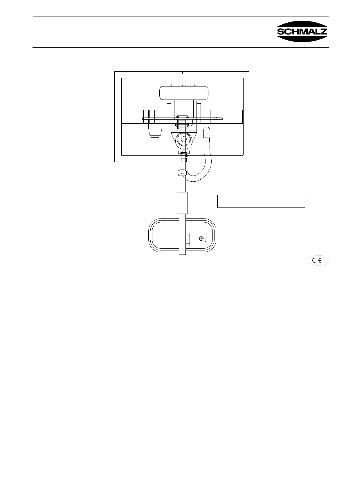
Operating Manual
VACUMASTER Multi-Serie
BA 30.30.01.00221-00
J. Schmalz GmbH
Aacher Straße 29
D - 72293 Glatten
Tel +49 +7443 / 2403 - 0
Fax +49 +7443 / 2403 - 259
http://www.schmalz.de
e-mail: [email protected]
VACUMASTER MULTI 400-1
Please keep this manual for future use
Status 03.2013 Page 1 / 18
Page 2
Operating Manual
VACUMASTER Multi-Serie
BA 30.30.01.00221-00
J. Schmalz GmbH
Aacher Straße 29
D - 72293 Glatten
Tel +49 +7443 / 2403 - 0
Fax +49 +7443 / 2403 - 259
http://www.schmalz.de
e-mail: [email protected]
Table of Contents
1 Safety
1.1 Instructions for the Company
1.2 Instructions for the Installation, Maintenance and Operating Personnel
1.3 Hazard Alert Messages in this Manual
1.4 Installation Site Requirements
1.5 Intended Use
1.6 Emissions
1.7 Special Hazards
1.8 Workplaces
1.9 Instructions for the Operator
1.10 Equipment for Personal Protection
1.11 Behaviour in Emergencies
1.12 Checking the safety devices
2 Technical Data
3 Description
3.1 Components of the Lifting Device
3.2 Blower with Reversing Device
3.3 Swivelling Unit (only MULTI ...-90°)
3.4 Controls
3.5 Suction boxes / pads
4 Installation
4.1 General
4.2 Adjusting the Load Suspension Device
5 Safety
5.1 Safety Instructions
5.2 Lifting Loads
5.3 Swivelling Loads
5.4 Releasing Loads
5.5 Switch on / off the back suction pad row
5.6 Moving the Lifting Device with the Chain Hoist
6 Troubleshooting
7 Maintenance
7.1 General
7.2 Maintenance
7.3 Checking the Air Gap of the Spring-Pressure Brake (only MULTI ...-90°)
7.4 Adjusting the spring-pressure brake
7.5 Changing the Oil in the Gearbox of the Swivel Unit (only MULTI ...-90°)
7.6 Vacuum blower
7.7 Suction Pads / Seals
7.8 Leak Test
7.9 Inspection by a Qualified Person
8 Notes on the nameplate
9 Guarantee, spare and consumable parts
Status 03.2013 Page 2 / 18
Page 3
Operating Manual
VACUMASTER Multi-Serie
BA 30.30.01.00221-00
J. Schmalz GmbH
Aacher Straße 29
D - 72293 Glatten
Tel +49 +7443 / 2403 - 0
Fax +49 +7443 / 2403 - 259
http://www.schmalz.de
e-mail: [email protected]
Appendix
Operating Manual Blower Gebl K10 DG 14
Spare Part List Blower Gebl K10 DG 14
Electrical Connection Diagram
EU - Conformity Declaration
Special features:
The unit is equipped with the following special feature(s):
.......................................................................................................................
.......................................................................................................................
.......................................................................................................................
.......................................................................................................................
.......................................................................................................................
(See the Appendix for special operating instructions and spare parts.)
If the special features require a separate list of spare parts or parts subject
of consumption, the corresponding list in section "Spare parts" is invalid.
Status 03.2013 Page 3 / 18
Page 4
Operating Manual
VACUMASTER Multi-Serie
Chapter 1
Safety
J. Schmalz GmbH
Aacher Straße 29
D - 72293 Glatten
Tel +49 +7443 / 2403 - 0
Fax +49 +7443 / 2403 - 259
http://www.schmalz.de
e-mail: [email protected]
1.1 Instructions for the
Company
Lifting devices of the series VACUMASTER have been manufactured according
to current technical standards and are safe. Still, they will present hazards
if they are not operated by qualified or at least trained staff,
if they are used contrary to the approved applications (see 1.4)
Problems can arise
for the health and life of operators and other persons,
for the lifting device and other valuable goods.
1.2 Instructions for the
Installation,
Maintenance and
Operating Personnel
The device must be installed and maintained by qualified personnel, mechanics
and electricians. Any work on the electrical equipment may be carried out only
by a qualified electrician.
Each person in your company involved in the installation, start-up, operation,
maintenance, and repair of the device
must have read and understood the operating instructions
and especially the chapter "Safety" therein.
Your company must ensure by internal measures
that the operators of the lifting device are properly trained,
that they have read and understood the operating instructions,
that the operating instructions will be available to them at any time.
The responsibilities for the tasks carried out with the device must be clearly
organized and observed. Ambiguity regarding responsibilities must not exist.
1.3 Hazard Alert
Messages in this
Manual
The hazard alert messages in this manual are labelled as follows:
Danger
Identifies imminent hazard. If you do not avoid it, death or severe injury
will result.
Caution
Identifies a potentially hazardous situation. If you do not avoid it, minor or
moderate injury can result.
1.4 Installation Site
Requirements
The lifting device must not be operated in rooms with explosive atmosphere.
It must be connected to the power supply of the crane or to the construction
machine it is used with. Thus it will be switched on and off together with the
respective machine.
The ambient temperature must be between +0°C and 40 °C
(if this temperature range is exceeded talk to the manufacturer).
Ensure by internal instructions and checks that the installation site is totally
clean and well organized.
1 Safety
BA 30.30.01.00221-00 Status 03.2013 Page 4/18
Page 5
Operating Manual
VACUMASTER Multi-Serie
Chapter 1
Safety
J. Schmalz GmbH
Aacher Straße 29
D - 72293 Glatten
Tel +49 +7443 / 2403 - 0
Fax +49 +7443 / 2403 - 259
http://www.schmalz.de
e-mail: [email protected]
1.5 Intended Use
Lifting devices series VACUMASTER MULTI are designed to lift and transport flat
and slightly bent boards of various materials, e.g. wood, particle board,
sheet-metal or plastic boards. The boards may have porous surfaces.
When using lifting devices with a single suction box the load have to be flat.
Caution
The maximum lifting capacity must not be exceeded.
Observe the name plate.
Danger
Transport of persons and animals with the load or the lifting device
itself is forbidden!
Unauthorized alteration of the lifting device is forbidden for safety
reasons!
The operating, maintenance and service instructions in this manual
must be observed.
1.6 Emissions
The equivalent continuous sound pressure level of the lifting device is
below 75 dB(A).
1.7 Special Hazards
Danger
Since the load is retained by a vacuum it will fall off as soon as this
vacuum is lost.
This happens in a sudden power failure. An alarm signal switches on.
When power fails immediately put the load down if possible. If this is not
possible, immediately leave the dangerous area near the load
Danger
The device generates a very strong suction which can draw in hair and
clothing. Do not look into the suction opening when the device is
switched on. Parts of body can be sucked in.
1.8 Workplaces
The workplace of the operator is in front of the control handle. Stand in a
position that allows you to keep a constant eye on the vacuum pressure gauge.
1.9 Instructions for the
Operator
As an operator of the lifting device you must be trained before start-up.
You must have read and understood the operating instructions and especially
the chapter "Safety".
Be sure, that only authorized persons use the device. You are responsible for
others in the operating range of the equipment.
Local safety requirements are fully applicable. Safety instructions in this
document are complementary to the rules in force and do not supersede the
latter.
1.10 Equipment for
Personal Protection
When operating the device always wear:
safety shoes (with steel top),
tough gloves.
1.11 Behaviour in
Emergencies
An emergency situation exists when
power suddenly fails (device switches off), a horn signal sounds.
the vacuum pressure drops below -0.125 bar to the red section on the scale
of the pressure gauge, a horn signal sounds.
Put the load down immediately if possible. If this is not possible, immediately
leave the dangerous area near the load. It will fall off!
BA 30.30.01.00221-00 Status 03.2013 Page 5/18
Page 6
Operating Manual
VACUMASTER Multi-Serie
Chapter 1
Safety
J. Schmalz GmbH
Aacher Straße 29
D - 72293 Glatten
Tel +49 +7443 / 2403 - 0
Fax +49 +7443 / 2403 - 259
http://www.schmalz.de
e-mail: [email protected]
1.12 Checking the safety
devices
The lifting device is equipped with following guards:
pressure gauge
alarm signal (acoustical)
covering of the toothed quadrant (only MULTI ...-90°)
pinion protection at the swivel gear (only MULTI ...-90°)
Check these guards
at the beginning of each shift (when operating in shifts),
once a week (when operating continually).
Checking the suction
hoses and hose clamps:
Check all suction hoses and clamps for proper mounting, if necessary retighten
the clamps.
Checking the warning
signal :
Switch on the lifting device.
Place it on a board, suck the board..
Danger
Attention: Only suck on the piece do not lift it !
The piece can loosen by the check an fall down !
When the vacuum pressure has been built up create a leakage spot on
the seal of the suction box.
The vacuum pressure indicated by the gauge decreases. When the
pointer reaches the red danger zone the warning signal must switch
on
Checking covers
(only MULTI ...-90°)
Check whether the covering of the toothed quadrant and the pinion
protection at the swivel gear are solid mounted.
Correct faults before operating the device. If faults occur during operation,
switch the device off and correct the faults before continuing work with the
device.
BA 30.30.01.00221-00 Status 03.2013 Page 6/18
Page 7
Operating Manual
VACUMASTER Multi-Serie
Chapter 2
Technical Data
J. Schmalz GmbH
Aacher Straße 29
D - 72293 Glatten
Tel +49 +7443 / 2403 - 0
Fax +49 +7443 / 2403 - 259
http://www.schmalz.de
e-mail: [email protected]
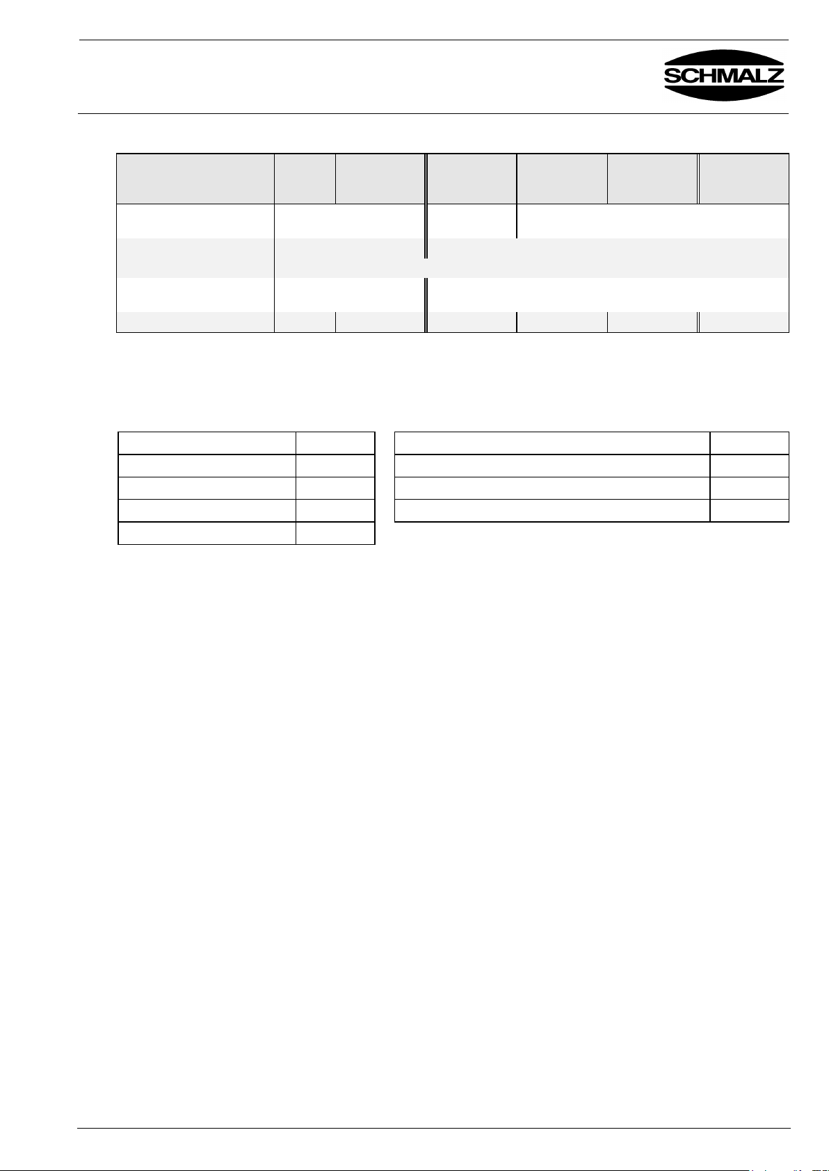
Type
VM
MULTI
400-1
VM MULTI
400-2
VM MULTI
400/150-90°-1
VM MULTI
400/300-90°-1
VM MULTI
400/300-90°-2
VM MULTI
400/300-90°-8
Maximum permissible
load*
400 kg
400 kg horiz.
150 kg vert.
400 kg horizontal
300 kg vertical
Handling
horizontal lifting
horizontal lifting & 90°-swivelling
Electric (Blower)
50 Hz: 3~ 230/400 V; 0,95 kW (optional 60 Hz: 3~ 255/440 V; 1,6 kW)
Electric (swivelling motor)
- 50 Hz: 3~ 230/400 V; 0,25 kW
60 Hz: 3~ 250/440 V; 0,25 kW
Weight
ca. 75 kg
ca. 105 kg
ca. 105 kg
ca. 130 kg
ca. 135 kg
ca. 120 kg
Frequency of network
50 Hz
Underpressure max.
180 mbar
Voltage / Blower
230/400 V
Noise Level
72 dB
Voltage / Reversing valve
24 V
Admissible tensile load on the suspension bolt
600 kg
Motor capacity
0,95 kW
Admissible support load on the suspension bolt
600 kg
Suction capacity
168 m³/h
2 Technical Data
*The maximum permissible load is specified for a vacuum of –125 mbar with all suction pads applied to the
workpiece. A coefficient of friction of µ=0.5 between the suction pads and the workpiece is assumed
(if necessary, determine the actual friction factor!!).
BA 30.30.01.00221-00 Status 03.2013 Page 7/18
Page 8
Operating Manual
VACUMASTER Multi-Serie
Chapter 3
Description
J. Schmalz GmbH
Aacher Straße 29
D - 72293 Glatten
Tel +49 +7443 / 2403 - 0
Fax +49 +7443 / 2403 - 259
http://www.schmalz.de
e-mail: [email protected]
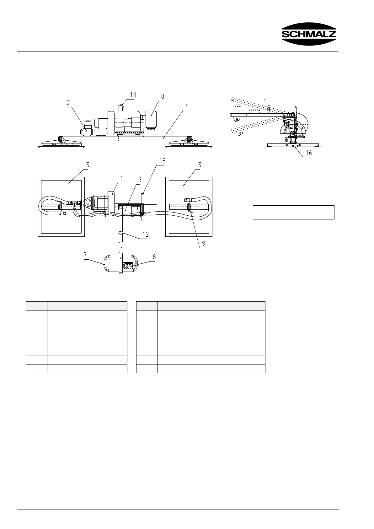
Pos.
Description
Pos.
Description
1
Blower
8 Switch box
2
Reversing Device
9 Clamping lever
3
Swivelling Unit
12
Pressure gauge
4
Load Suspension Device
13
Eye bolt
5
Suction box / Suction pad
14
Horn
6
Controls
15
Pinion protection
7
Operating handle
16
Limit switch for workpiece inquiry
MULTI 400/300-90°-2
/14
3 Description
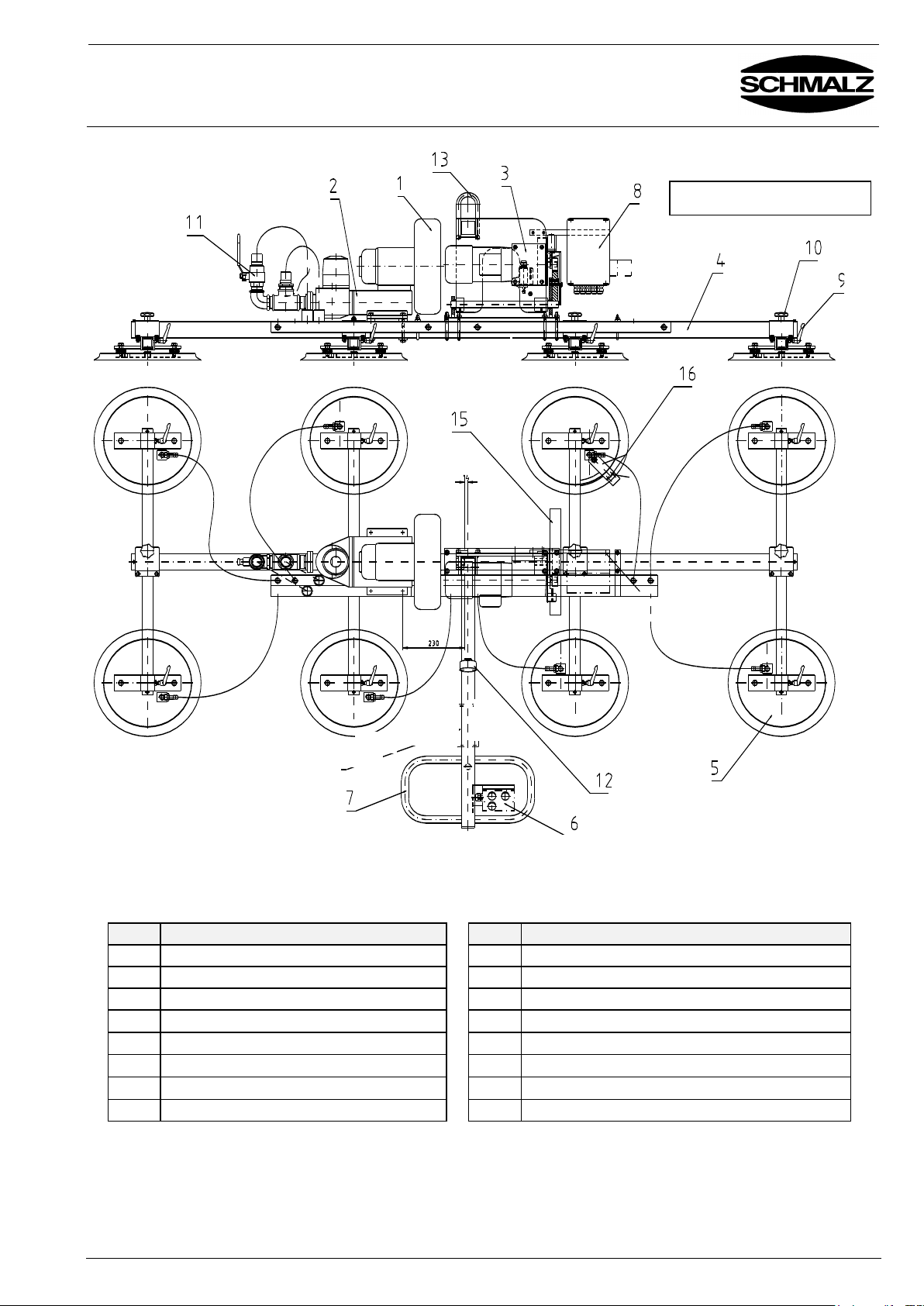
3.1 Components of the Lifting Device
The parts with safety function appear in bold type
BA 30.30.01.00221-00 Status 03.2013 Page 8/18
Page 9
Operating Manual
VACUMASTER Multi-Serie
Chapter 3
Description
J. Schmalz GmbH
Aacher Straße 29
D - 72293 Glatten
Tel +49 +7443 / 2403 - 0
Fax +49 +7443 / 2403 - 259
http://www.schmalz.de
e-mail: [email protected]
Pos.
Description
Pos.
Description
1
Blower
9 Clamping lever
2
Reversing Device
10
Star grip
3
Swivelling Unit
11
Ball valve
4
Load Suspension Device
12
Pressure gauge
5
Suction pad
13
Eye bolt
6
Controls
14
Horn
7
Operating handle
15
Pinion protection
8
Switch box
16
Limit switch to inquiry work pieces
MULTI 400/300-90°-8
/14
The parts with safety function appear in bold type
BA 30.30.01.00221-00 Status 03.2013 Page 9/18
Page 10
Operating Manual
VACUMASTER Multi-Serie
Chapter 3
Description
J. Schmalz GmbH
Aacher Straße 29
D - 72293 Glatten
Tel +49 +7443 / 2403 - 0
Fax +49 +7443 / 2403 - 259
http://www.schmalz.de
e-mail: [email protected]
3.2 Blower with
Reversing Device
The blower produces the vacuum for the lifting device. It is fitted with a silencer
each on the sucking an the exhaust side. If a power failure occurs, its heavy
impeller produces a reserve vacuum for a short period. The blower motor must
be ventilated sufficiently. A motor overload switch protects the blower from
overload (see operating manual in appendix).
A reversing valve is connected to the suction side of the blower. It can quickly
change the blower from suction to pressure mode.
3.3 Swivelling Unit
(only MULTI ...-90°)
The swivelling unit swivels the load and support rail by max. 90°. This allows
you to put down boards vertically that you lifted up horizontally and vise versa.
An electrical motor with a swivelling gear box drives the unit. A springloaded
brake stops the swivelling.
In the beginning a thin grease residue may show on the drive shaft and air relief
valve. This is normal and no reason to worry.
3.4 Controls
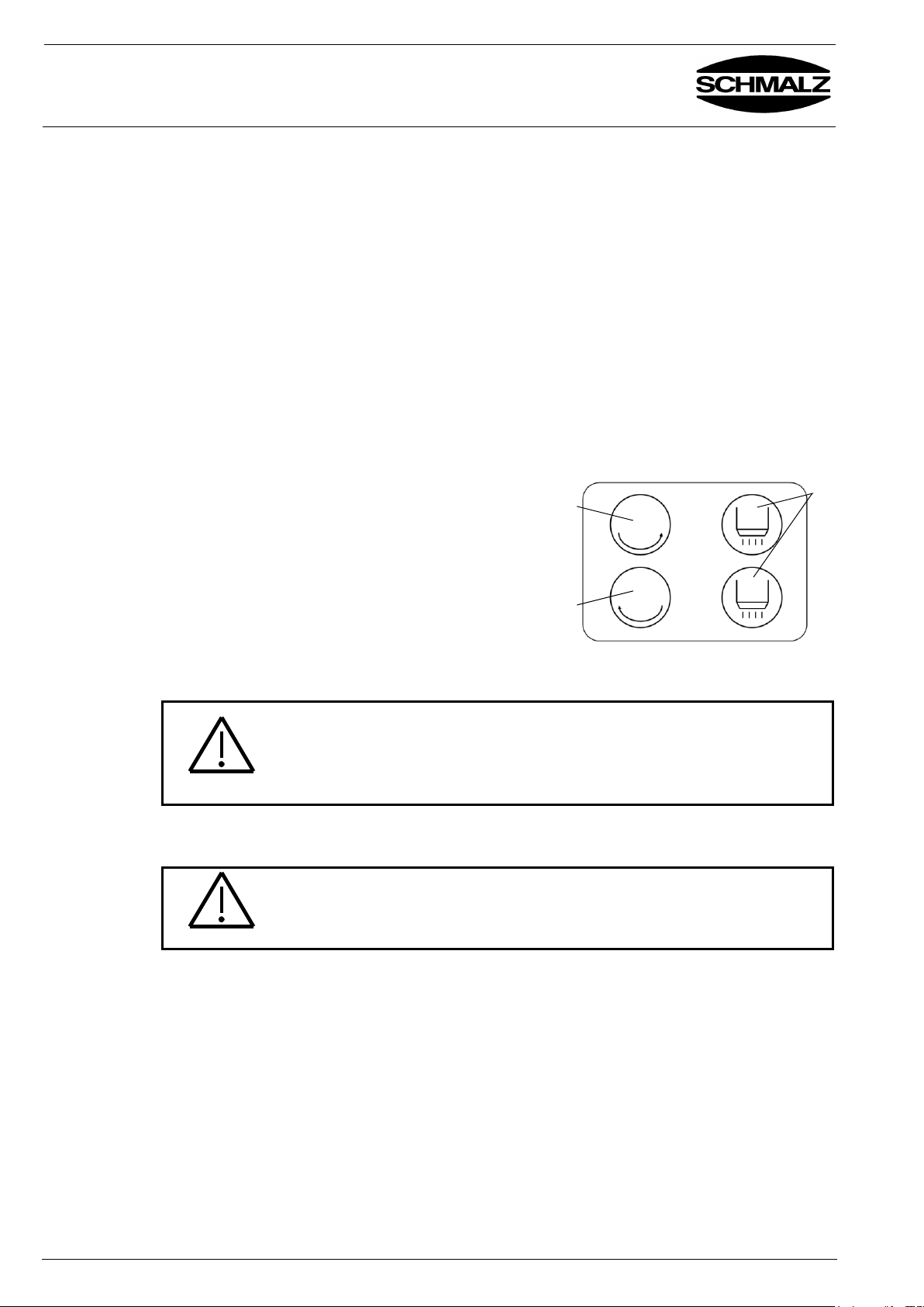
The controls are mounted right of the manipulator handle. It comprises the
following controls.
Button "Swivel vertically" (1),
Button "Swivel horizontally" (2),
2x "Release" button (3); the device
operates in suction mode unless these
buttons are activated. Both "Release"
buttons must be pressed simultaneously.
The buttons for swivelling are only
mounted by the types MULTI ...-90°.
3.5 Suction boxes / pads
The various suction boxes / pads apply the vacuum to the load. They are
designed to lift various items.
Danger
All suction boxes / pads have to rest on the workpiece and suction it.
Exception MULTI 400/300-90°-8:
All suction pads of the front suction pad row have to rest on the work
peace. Attention: The max. lifting capacity degrease on the halve.
Deactivate suction pads which did not suck on the load. In the other case no
vacuum can be generated.
Active or deactivate the suction pads only when no load is sucked on.
Danger
When activating or deactivating the suction pads when a load is lifted,
the vacuum breaks down all of a sudden, the load falls down.
1 2 3
BA 30.30.01.00221-00 Status 03.2013 Page 10/18
Page 11
Operating Manual
VACUMASTER Multi-Serie
Chapter 4
Installation
J. Schmalz GmbH
Aacher Straße 29
D - 72293 Glatten
Tel +49 +7443 / 2403 - 0
Fax +49 +7443 / 2403 - 259
http://www.schmalz.de
e-mail: [email protected]
4.1 General
The device must be installed and maintained by qualified personnel, mechanics
and electricians. Any work on the electrical equipment may be carried out only by a
qualified electrician.
.
Danger
The electrical connection must be made behind the disconnecting switch or
maintenance switch and in front of the main switch or emergency-stop
switch of the crane. When the main switch of the crane or the emergencystop switch are activated, the lifting unit must not switch off as this may be
dangerous
Installation
Suspend the lifting device from the suspension eye bolt on the crane or hoist
used. Fasten it safely! Observe the weight of the lifting device and the
maximum carrying capacity!
Pull the supply cable with plug from the control box. Connect the cable to the
power supply of the crane or hoist according to local regulations.
This job must be done by a qualified electrician.
Be sure, that the power supply is switched off!
Check rotation
direction
Before starting operation you have to check the rotation direction of the blower:
Switch on the blower.
Watch the fan of the blower motor. It must turn in the direction indicated by the
arrow on the motor housing.
If it rotates in the opposite direction, transpose the power connection of the
supply line.
Recheck the rotation direction.
4.2 Adjusting the Load
Suspension Device
The load suspension device is firmly screwed to the unit’s body.
Before starting operation check the screwed connections for proper fixing.
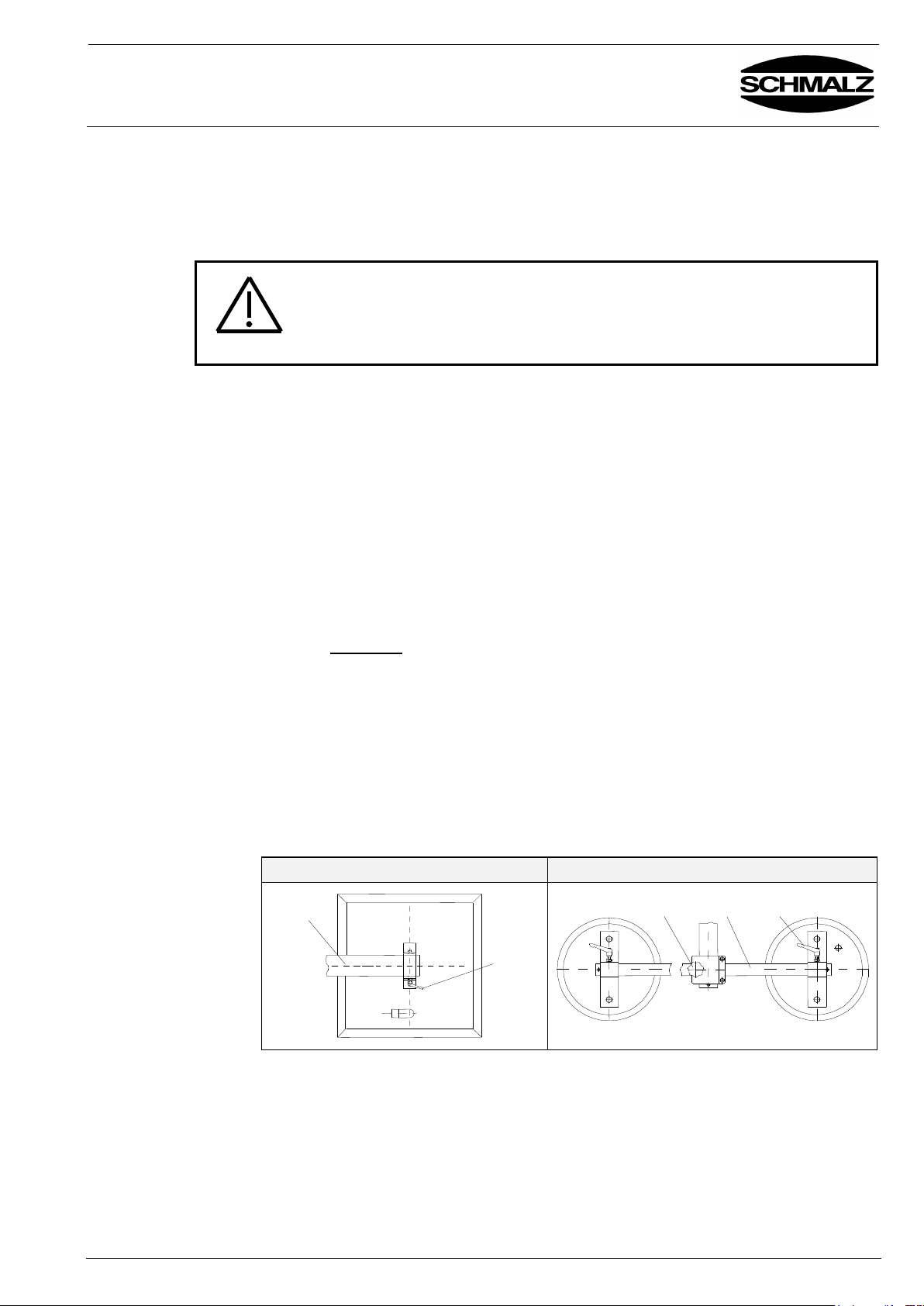
To alter the adjustments loosen the star-grip handles (2) / clamping lever (3) on the
glide shoes by one revolution. Adjust the rail or suction box to the desired position
and retighten the star-grip handle / clamping lever.
Be sure the load suspension device is adjusted symmetrically. Thereafter check
the vacuum connections (hoses).
All types except Multi 400/300-90°-8
Multi 400/300-90°-8
1
2
1
2
3
4 Installation
BA 30.30.01.00221-00 Status 03.2013 Page 11/18
Page 12
Operating Manual
VACUMASTER Multi-Serie
Chapter 5
Operation
J. Schmalz GmbH
Aacher Straße 29
D - 72293 Glatten
Tel +49 +7443 / 2403 - 0
Fax +49 +7443 / 2403 - 259
http://www.schmalz.de
e-mail: [email protected]
5.1 Safety Instructions
Local safety requirements are fully applicable. The following safety instructions are
complimentary to the rules in force and do not supersede the latter:
Wear safety shoes and gloves.
Never exceed the maximum lifting capacity of the device. Never exceed the
maximum lifting capacity of the crane or hoist used. Consider the weight of the
lifting device. Observe the name plate.
Do not stand below the load. Always keep clear of the load.
Never carry people or animals with the load or the lifting device itself!
Operate only when you can view the entire working area. Look out for other
persons in the working area. Never manoeuvre loads above people.
Do not let go of the handle whilst lifting a load.
Do not pull loads to the side or drag them along with the lifting device.
Do not rip loose loads that have become jammed.
When there is a power failure put the load down immediately if possible.
Immediately leave the danger area near the load.
Apply suction and lift only to appropriate loads (check for stability and porosity).
Always keep an eye on the pressure gauge. Never lift loads when the vacuum
is below -0.125 bar. When the pointer of the pressure gauge moves into the red
danger zone below -0.125 bar, put the load down immediately.
When the horn blows, put the load down immediately.
Land workpieces only on free, level surfaces. Otherwise they can slip away
when you land them.
Land load only when it has touched down entirely and safely. Fingers away
from the load when you land it. Severe bruises!
Always distribute load evenly on the suction surfaces.
Check all seals, suction hoses and claps daily.
Eliminate leakages before initiation.
Caution
The following operating steps must be checked by a qualified mechanic
prior to use of the device by the operating personnel. Correct faults before
start-up.
5.2 Lifting Loads
Warning
Switch the lifting device on.
Position the lifting device directly above the load. Do not pull sideways.
Distribute load evenly.
Put the lifting device down on the load. It suck on by itself.
Watch the pressure gauge. As soon as -0.125 bar has been reached you can
lift the load. Never lift the load before. It would fall off.
Caution
When lifting be sure to lift only one piece of the items to be lifted. Before lifting,
carefully remove other pieces sticking to the one you want to lift. Use a
screwdriver to do that. Do not separate them with your hands. Severe bruises!
5.3 Swivelling Loads
(only MULTI ...-90°)
Warning
Push the Button "Swivel vertically" (1) resp. "Swivel horizontally" (2).
Do not stand in the swivelling area!
Please pay attention by swivelling that the load does not crash against anything.
!! Accident hazard !!
5 Safety
BA 30.30.01.00221-00 Status 03.2013 Page 12/18
Page 13
Operating Manual
VACUMASTER Multi-Serie
Chapter 5
Operation
J. Schmalz GmbH
Aacher Straße 29
D - 72293 Glatten
Tel +49 +7443 / 2403 - 0
Fax +49 +7443 / 2403 - 259
http://www.schmalz.de
e-mail: [email protected]
5.4 Releasing Loads
Lower the load to a safe and vacant, level surface. When placing the load
vertically, make sure it is properly guided and cannot slip away or tip over.
Danger
Press both "Release" buttons (3). The load detaches itself.
Keep hands away from the load when activating a "Release" button.
Crushing hazard!
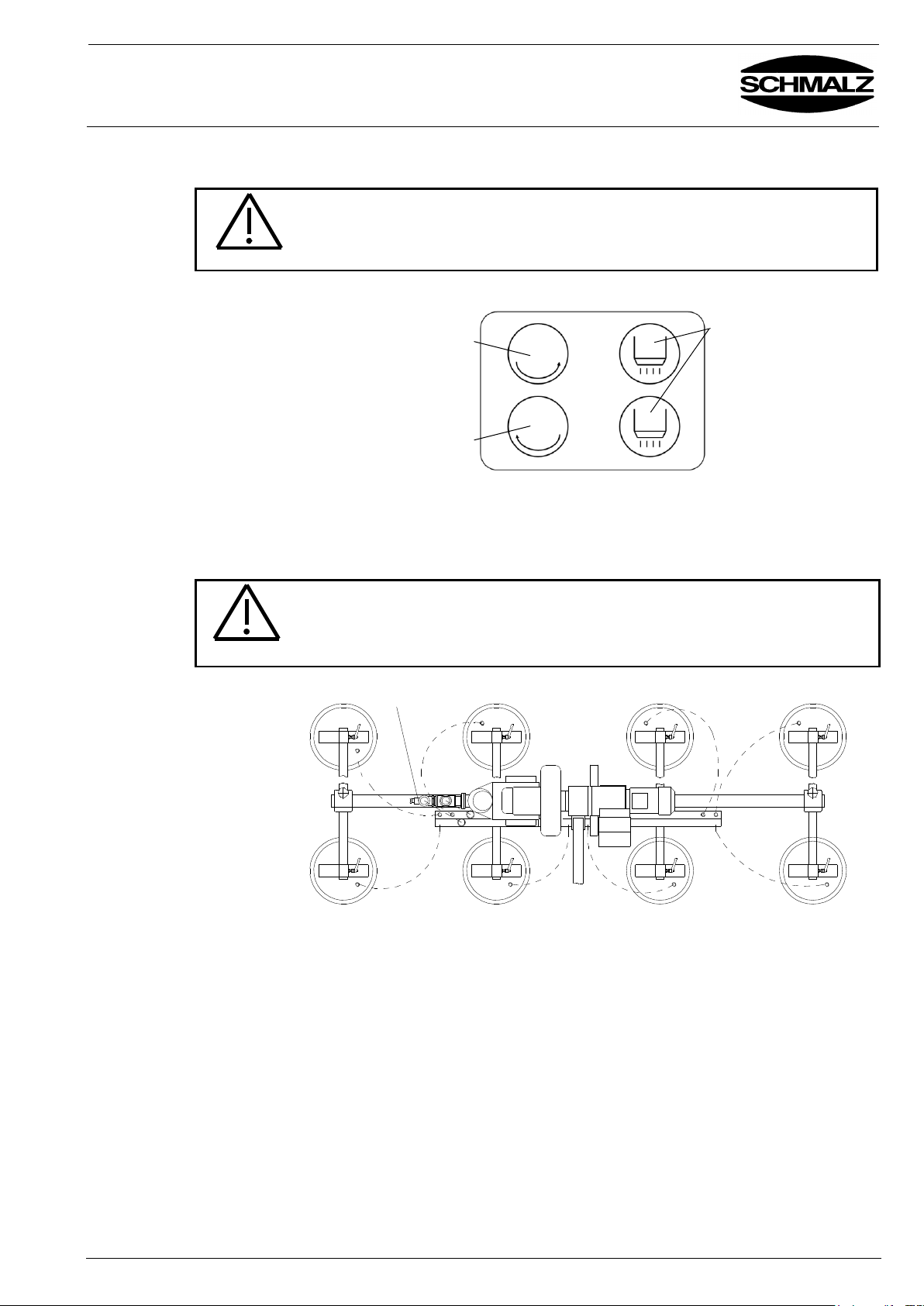
Hold both "Release" buttons (3) and raise the lifting device.
5.5 Switch on / off the
back suction pad
row
To remove boards from racks the back suction pad row can be switch on an off
with the ball valve (only MULTI 400/300-90°-8).
Attention: only switch on and off the back suction pad row in no-load condition.
Warning
Deactivating the back suction pad row reduces the load carrying capacity of
the device by the half
Front suction pad row
Back suction pad row
ball valve
5.6 Moving the Lifting
Device with the
Chain Hoist
Do not jerkily drive the lifting device because the device with the sucked on load
could get in rotation or pendulum motion.
Accident hazard !
1 2 3
BA 30.30.01.00221-00 Status 03.2013 Page 13/18
Page 14
Operating Manual
VACUMASTER Multi-Serie
Chapter 6
Trouble Shooting
J. Schmalz GmbH
Aacher Straße 29
D - 72293 Glatten
Tel +49 +7443 / 2403 - 0
Fax +49 +7443 / 2403 - 259
http://www.schmalz.de
e-mail: [email protected]
6 Troubleshooting
The device must be installed and maintained by qualified personnel,
mechanics and electricians. Any work on the electrical equipment may be
carried out only by a qualified electrician.
After each repair or maintenance job check the guards as described in the
Operating Manual “Safety”.
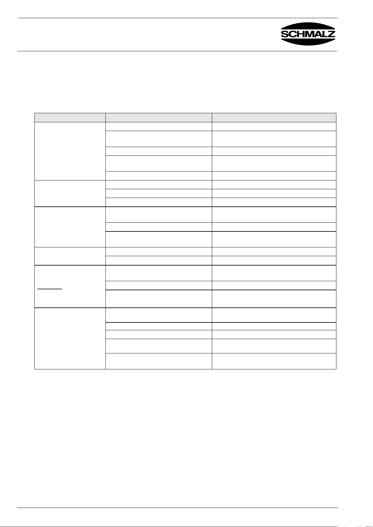
Error
Cause
Remedy
Blower does not run
wrongly connected
check and correct connection
motor overload switch tripped
check, motor for defect, thermal overload?
(let it cool down), clean dust filter
power on two phases only
check connection and fuse
current consumption too high
Check motor for defect, thermal overload?
(let it cool down), clean dust filter
power supply failure
Check supply line
Blower runs, but does
not suck
wrong rotation direction
Check and correct connection
reversing unit do not work
Check control reverse jammed, clean it.
filter get choked
Replace / clean filter
Blower dropped out
power on two phases only
Check connection and fuses
Check current consumption
supply power failure
Check supply line
current consumption too high
Check motor for defect, thermal overload?
(let it cool down), clean dust filter
Gear motor does not
run
supply power failure
Check supply line
gear motor defective
Repair / replace gear motor
Vacuum pressure does
not reach -0.125 bar
DANGER!
Do not lift the item. It will
fall off!
workpiece has cracks, openings or is
porous
- - -
seal damaged
Glue it, replace seal
pressure gauge defective
replace pressure gauge
Horn blows without a
recognizable reason
Workpiece has cracks or openings
or is porous
Such workpieces cannot be handled with
this lifting device
Sealing lip / suction pad is damaged
Replace the sealing lip / suction pad
hose defective / connectors not tight
replace components
Vacuum switch defective or set
wrongly
Call customer service
Limit switch to inquiry work pieces
defective
Check connection, readjust / replace
BA 30.30.01.00221-00 Status 03.2013 Page 14/18
Page 15
Operating Manual
VACUMASTER Multi-Serie
Chapter 7
Maintenance
J. Schmalz GmbH
Aacher Straße 29
D - 72293 Glatten
Tel +49 +7443 / 2403 - 0
Fax +49 +7443 / 2403 - 259
http://www.schmalz.de
e-mail: [email protected]
7.1 General
The device must be installed and maintained by qualified personnel,
mechanics and electricians. Any work on the electrical equipment may be
carried out only by a qualified electrician.
The fan, reversing and turning unit must not be opened during the
guarantee period as this will entail loss of guarantee cover.
After each repair or maintenance job check the guards as described in
chapter "Safety".
Use cleaning agent to clean the device (do not use petrol (gasoline) or
aggressive or corrosive fluids to clean the device. The hoses will otherwise
become leaky or be destroyed).
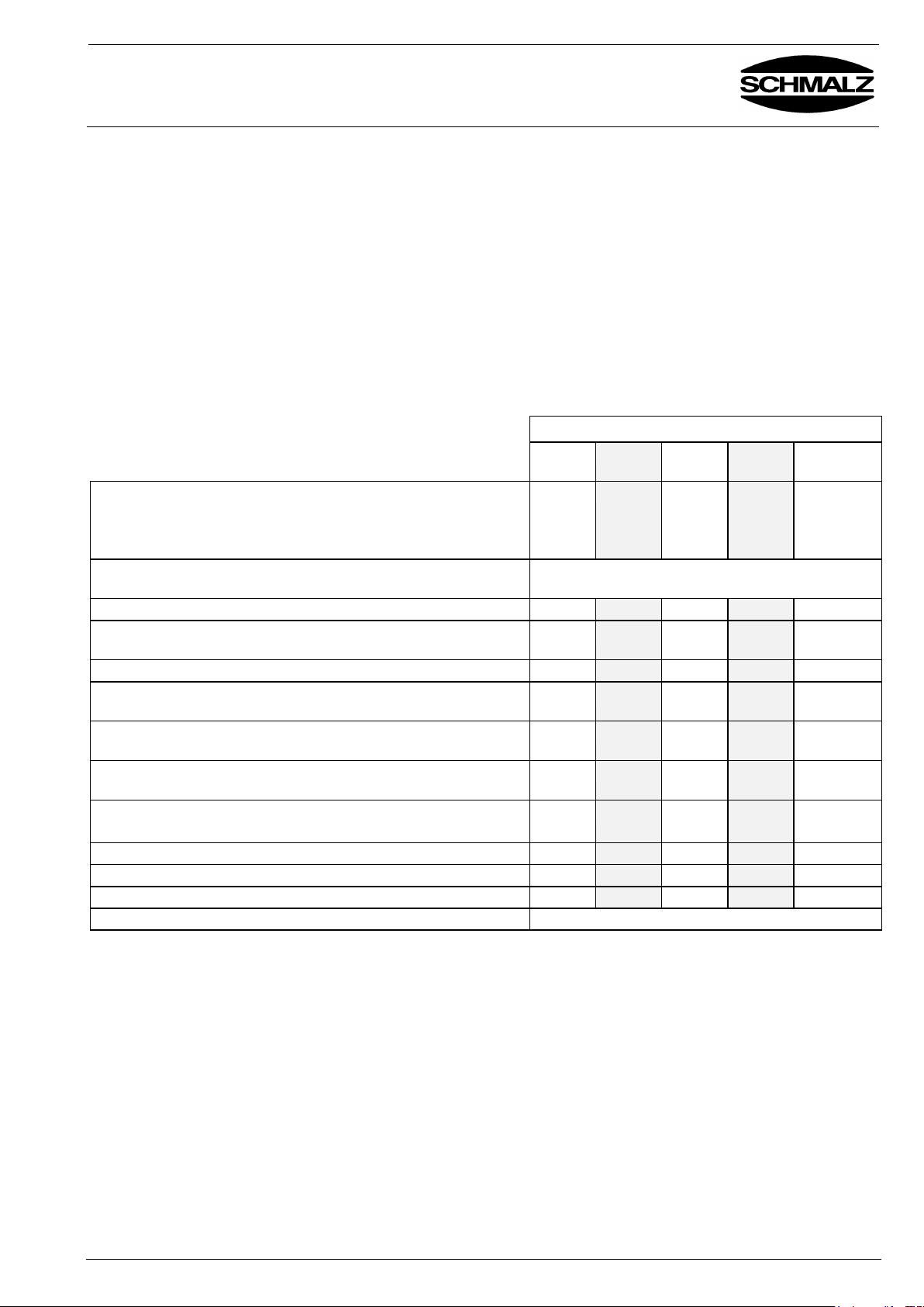
7.2 Maintenance
Interval
Daily
Weekly
Monthly
Every 6
months
Every 12
months
Inspect the safety devices:
- Vacuum gauge OK?
- Warning device actuated at correct pressure/vacuum value?
- On swivelling devices: gearwheel cover securely fitted?
X X
Inspect and maintain the blower and reversing unit as
described in the operating instructions
See operating instructions for blower and reversing
unit
Electrical equipment OK? Cable glands tight?
X
Vacuum hoses in good condition (no cracks, not kinked, no
abrasion, free of leaks)?
X X
All connections (hose clamps, etc.) tight?
X
Instruction plate, rating plate and load plate still mounted on the
device?
X
Operating instructions available?
Operating personnel familiar with operating instructions?
X
Inspect load-carrying part (such as suspension) for
deformation, wear and other damage.
x
Clean and inspect suction pads. Must be free of cracks, lip
must be smooth, etc. Replace if necessary.
X
X
Is the inspection sticker up to date?
X
General condition of the device.
X
Leak test
X X
On swivelling units: change gearbox oil.
See section 7.6
7.3 Checking the Air Gap
of the Spring-Pressure
Brake
(only MULTI ...-90°)
Due to wear, the braking power of the spring-pressure brake may be reduced
considerably.
If you notice that the load does not immediately stop moving when the swivel
valve is released, the air gap of the brake must be adjusted without delay.
(This air gap may not exceed 0.6 mm.)
7 Maintenance
BA 30.30.01.00221-00 Status 03.2013 Page 15/18
Page 16
Operating Manual
VACUMASTER Multi-Serie
Chapter 7
Maintenance
J. Schmalz GmbH
Aacher Straße 29
D - 72293 Glatten
Tel +49 +7443 / 2403 - 0
Fax +49 +7443 / 2403 - 259
http://www.schmalz.de
e-mail: [email protected]
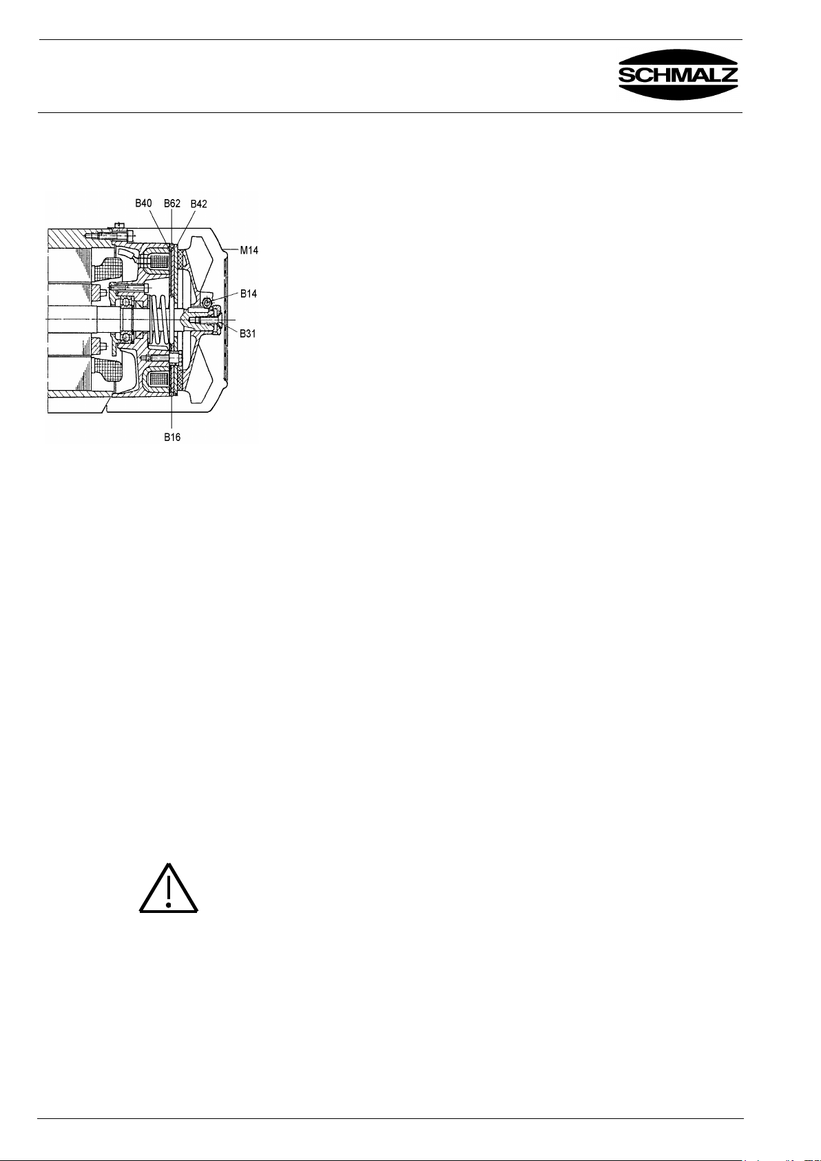
7.4 Adjusting the springpressure brake
(only Multi ...-90°)
Remove the actuator cover M14.
Loosen the actuator clamping screws B14.
Remove the O-Ring B62 and insert shims B40 between the armature
plate B42 and the plate B16 (thickness of shims B40: 0.25 - 0.30 mm).
Tighten screw B31 until the shims can still just be removed.
Tighten the actuator clamping screws B14 uniformly, beginning with the
screw opposite the key slot (tightening torque: 5.5 Nm).
Tighten screw B31 again.
Remove the shims B40.
Install the actuator cover M14.
Test the operation of the brake.
Brake type: EFB 2
Nominal braking torque: 7.5 Nm
Air gap, max.: 0.6 mm
Adjusting shims: 0.25 - 0.30 mm
Pressure spring color: black
7.5 Changing the Oil in the
Gearbox of the Swivel
Unit (only MULTI ...-90°)
The oil in the gearbox of the swivel head must be changed after 10,000
operating hours or after three years, whichever occurs sooner. Oil capacity:
0.2 litres. To change the oil, first open and clean the gearbox and check the
condition of all parts subject to wear. Fit new shaft sealing rings.
The specifications apply for operation under normal conditions, at ambient
temperatures in the range -10°C to +40°C.
Recommended oil: Aral Degol BMB 680. At temperatures in the range -10°C
to -20°C, use Degol BMB 220+, at temperatures below -20°C BMB 46+.
Equivalent oil types:
Aral Degol BMB 220
BP Energol GR-xP 220
Calypsol Bison Oel MSR 114
ESSO Spartan EP-220
Houghton Molygear 115
Mobil Mobilgear 630
Shell Omala 220
Before assembly, clean the housing gaskets and apply a plastic sealing
compound (such as Dirko).
Refill the gearbox. Never mix mineral and synthetic oils.
7.6 Vacuum blower
See operating manual in appendix.
7.7 Suction Pads / Seals
Warning
Remove items and contaminations such as adhesives, glue, saw dust, dust
etc. sticking to the seals at least once a week. Use glycerine to clean the
seals.
Immediately replace damaged seals (tears, holes, waves).
BA 30.30.01.00221-00 Status 03.2013 Page 16/18
Page 17
Operating Manual
VACUMASTER Multi-Serie
Chapter 7
Maintenance
J. Schmalz GmbH
Aacher Straße 29
D - 72293 Glatten
Tel +49 +7443 / 2403 - 0
Fax +49 +7443 / 2403 - 259
http://www.schmalz.de
e-mail: [email protected]
7.8 Leak Test
Check the device for leaks once per month.
Place the suction pads on an airtight, smooth surface such as a sheet of
metal.
Switch on the vacuum blower and suck on the workpiece.
A vacuum of at least –0.15 bar has to be reached.
If you don´t reach this vacuum, check:
the suction pads, seals, hoses, connections for damage or leaks,
if so, clean or replace it.
7.9 Inspection by a
Qualified Person
Accident prevention rules require a yearly inspection of lifting device and crane by
a qualified person.
BA 30.30.01.00221-00 Status 03.2013 Page 17/18
Page 18
Operating Manual
VACUMASTER Multi-Serie
Chapter 8 / 9
Nameplate / Spare and
consumable parts
J. Schmalz GmbH
Aacher Straße 29
D - 72293 Glatten
Tel +49 +7443 / 2403 - 0
Fax +49 +7443 / 2403 - 259
http://www.schmalz.de
e-mail: [email protected]
8 Notes on the
Nameplate
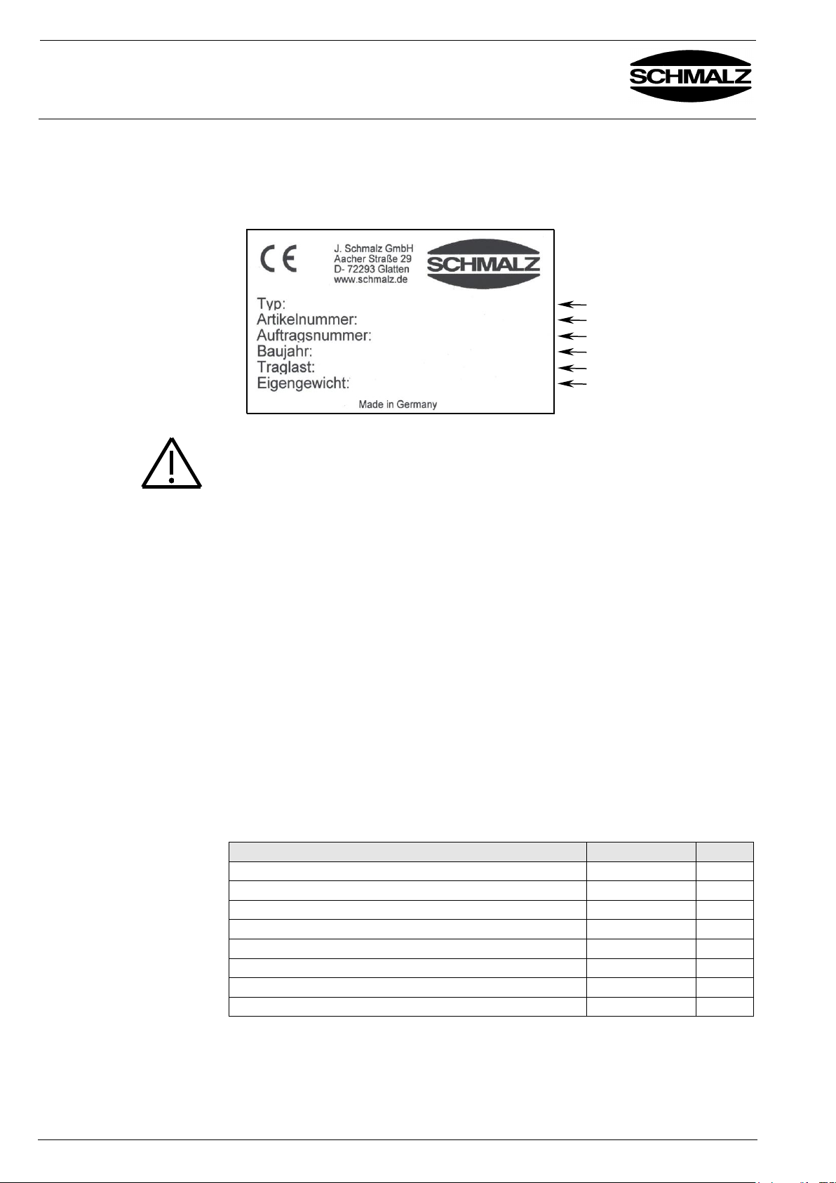
On the nameplate the main data for the lifting device is indicated.
The nameplate is firmly connected to the device. Its position is shown in the
"Spare parts list".
The nameplate contains the following information:
Seite / Page 1/1 03.2000
Fax +49 +7443 / 2403 - 259
e-mail: schmalz@schmalz.de
Type
Device Number
Order Number
Year of construction
Max. lifting capacity
Weight of device
Caution
Type, no. and year of construction are vital for identification of the unit. Indicate
these when ordering spares or filing claims and other inquiries.
The max. lifting capacity indicates for which maximum load the device can be
used. The max. load must not be exceeded.
This equipment is guaranteed in accordance with our General Conditions of
Business. This also applies to spare parts where these are original parts supplied
by us.
We will assume no liability for damage caused by the use of non-original spare
parts and accessories.
Wear and consumable parts are not covered by the guarantee.
The most important spare and consumable parts are shown in the following list.
Abbreviations: - Spare part = E
- Consumable part = V
- Consumable-part assembly, contains consumable parts = VB
Description
Article-No.
Legende
Vacuum gauge VAM 63/250 H
10.07.02.00006
E
Seal for suction box 1500 x 800
12.01.02.10261
V
Sealing lip for suction box 1000 x 675
12.01.01.10094
V
Suction pad SPL 400 (Multi 400/300-90°-8)
10.01.01.01138
V
Seal for suction pad SPL 400 (Multi 400/300-90°-8)
10.01.01.01136
V
Warning device complete
10.07.05.00002
E
Vacuum switch VS-V-A-PNP-S for warning device
10.06.02.00062
E
Operating housing, safety device for wrong operation
12.02.05.10046
E
9 Guarantee, spare and consumable parts
BA 30.30.01.00221-00 Status 03.2013 Page 18/18
 Loading...