

Page 1
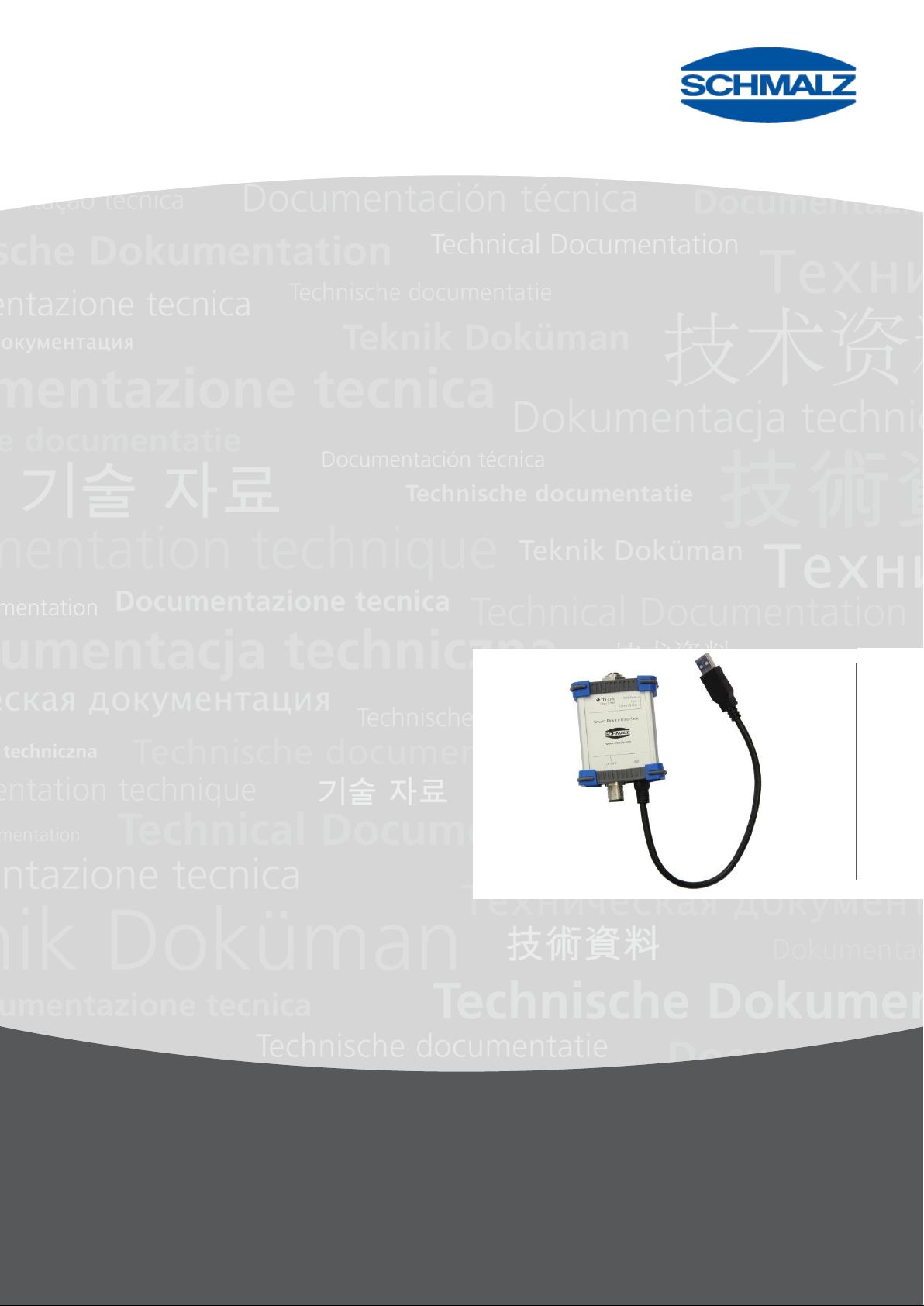
Innovative Vacuum for Automation
EN
Operating Instructions
Smart Device Interface SDI-USB
30.30.01.00953/01 | 04.2016
www.schmalz.com
Page 2

Note
These operating instructions were originally written in German and have been translated into English.
Store in a safe place for future reference.
We reserve the right to make technical changes. No responsibility is taken for printing or other types of
errors.
Published by
© J. Schmalz GmbH, 04.2016
This document is protected by copyright. J. Schmalz GmbH retains the rights established thereby.
Reproduction of the contents, in full or in part, is only permitted within the limits of the legal provisions
of copyright law. Any modifications to or abridgments of the document are prohibited without explicit
written agreement from J. Schmalz GmbH.
Contact
J. Schmalz GmbH
Aacher Strasse 29
D-72293 Glatten, Germany
Tel. +49 (0) 7443 2403-0
Fax +49 (0) 7443 2403-259
[email protected]
www.schmalz.com
Contact information for Schmalz companies and trade partners worldwide can be found at
www.schmalz.com/ vertriebsnetz
www.schmalz.com
Page 3

Contents
Smart Device Interface SDI-USB
1 Safety Instructions ............................................................................................... 4
1.1 Classification of safety instructions ................................................................................... 4
1.2 Warnings and Mandatory symbols .................................................................................... 4
1.3 General safety instructions ................................................................................................ 5
1.4 Intended use ...................................................................................................................... 5
2 Product Description ............................................................................................. 6
2.1 General .............................................................................................................................. 6
2.2 Included in delivery ............................................................................................................ 6
2.3 Frontview and Interfaces ................................................................................................... 7
3 Design and function ............................................................................................ 8
3.1 Design ............................................................................................................................... 8
3.2 Function ............................................................................................................................. 8
3.3 Display elements ............................................................................................................... 8
4 Electrical connection ........................................................................................... 9
4.1 Connecting the SDI-USB electrically ................................................................................. 9
4.1.1 Supply and interface .......................................................................................................... 9
4.2 USB connection diagram ................................................................................................... 9
4.3 IO-Link connection diagram ............................................................................................10
5 Technical data ................................................................................................... 10
5.1 Ambient conditions ..........................................................................................................10
6 Installing software ............................................................................................. 11
6.1 Installing software ............................................................................................................11
6.2 Installation .......................................................................................................................11
7 Maintenance...................................................................................................... 17
7.1 Cleaning ..........................................................................................................................17
7.2 Troubleshooting ...............................................................................................................17
7.3 Disposal ...........................................................................................................................17
8 Conformity Declaration ...................................................................................... 18
www.schmalz.com
Page 4

SAFETY INSTRUCTIONS
WARNING
Type and source of the Danger
Consequence
►
Remedial action
CAUTION
Type and source of danger
Consequence
►
Remedial action
Note/Information
Warning symbol
Description
Mandatory
symbol
Description
Warning of environmental damage
Adhere to the operating instructions
1 Safety Instructions
1.1 Classification of safety instructions
Only the instructions that are used in the following operating instructions are listed.
Warning
This warning informs the user of a risk that could result in death or serious injury if it is not avoided.
Caution
This warning informs the user of a risk that could result in damage to property if it is not avoided.
General notes
This symbol is used when important notes and information regarding use of the machine/the
system/the device are provided.
1.2 Warnings and Mandatory symbols
Explanation of the warning symbols used in the operating instructions.
4 | EN www.schmalz.com 30.30.01.00953/01
Page 5
SAFETY INSTRUCTIONS
WARNING
Ignoring the general safety guidelines
Personal injuries / damage to plants/systems
►
The operating instructions contain important information on using the SDI-USB.
Read the operating instructions thoroughly and keep them for later reference.
►
The system may only be connected and operations started once the operating
instructions have been read and understood.
►
Use only the connections, mounting holes and attachment materials that have
been provided
►
Carry out mounting or disassembly work only when the device is disconnected
from the power supply.
►
Installation may only be carried out by qualified specialist personnel,
mechanics and electricians. Qualified specialist personnel are persons who
have the knowledge and experience – including knowledge of applicable
regulations – necessary to enable them to recognize possible dangers and
implement the appropriate safety measures while performing the tasks
►
General safety regulations, European standards and VDE guidelines must be
observed and complied with.
►
It is not permitted to make changes to system components.
►
Protect the components from damage of any kind.
1.3 General safety instructions
1.4 Intended use
The SDI-USB serves as an interface between an IO-Link device and a Laptop or PC with a Windows
operating system. Together with the SDI-USB-HMI software program, IO-Link devices can be
operated, read out and parameterized..
SCHMALZ does not accept any liability for any direct or indirect losses or damages that result from
using the product. This applies, in particular, to any use of the product that is is not in accordance with
the intended purpose and to any use that is not described or mentioned in this documentation.
30.30.01.00953/01 www.schmalz.com EN | 5
Page 6

PRODUCT DESCRIPTION
2 Product Description
2.1 General
The SDI-USB is an IO-Link Class B - USB master.
2.2 Included in delivery
Schmalz part number 21.10.02.00017 is included in delivery.
1 SDI-USB Art-No. 21.10.02.00013
1 M12 cable, 5-pole Art-No. 21.04.05.00158
1 mains power adapter Art-No. 21.07.01.00070
1 SDI-USB operating instructions Art-No. 30.30.01.00953
1 USB-Stick with the latest Operator Software-version
for Laptops and PCs Art-No. 21.10.02.00008
Accessories (not included in scope of delivery):
1 cable ASV IO-L-A 2xB-M12-5 10.02.02.04436
for SX(M)Pi / x-Pump with connection
2x M12 - 5 pins (Y-type) only
1 cable ASK-S B-M12-8 1000 M12-4 PUR 21.04.05.00167
for SX(M)Pi / x-Pump with connection M12 - 8 pins only
6 | EN www.schmalz.com 30.30.01.00953/01
Page 7
PRODUCT DESCRIPTION
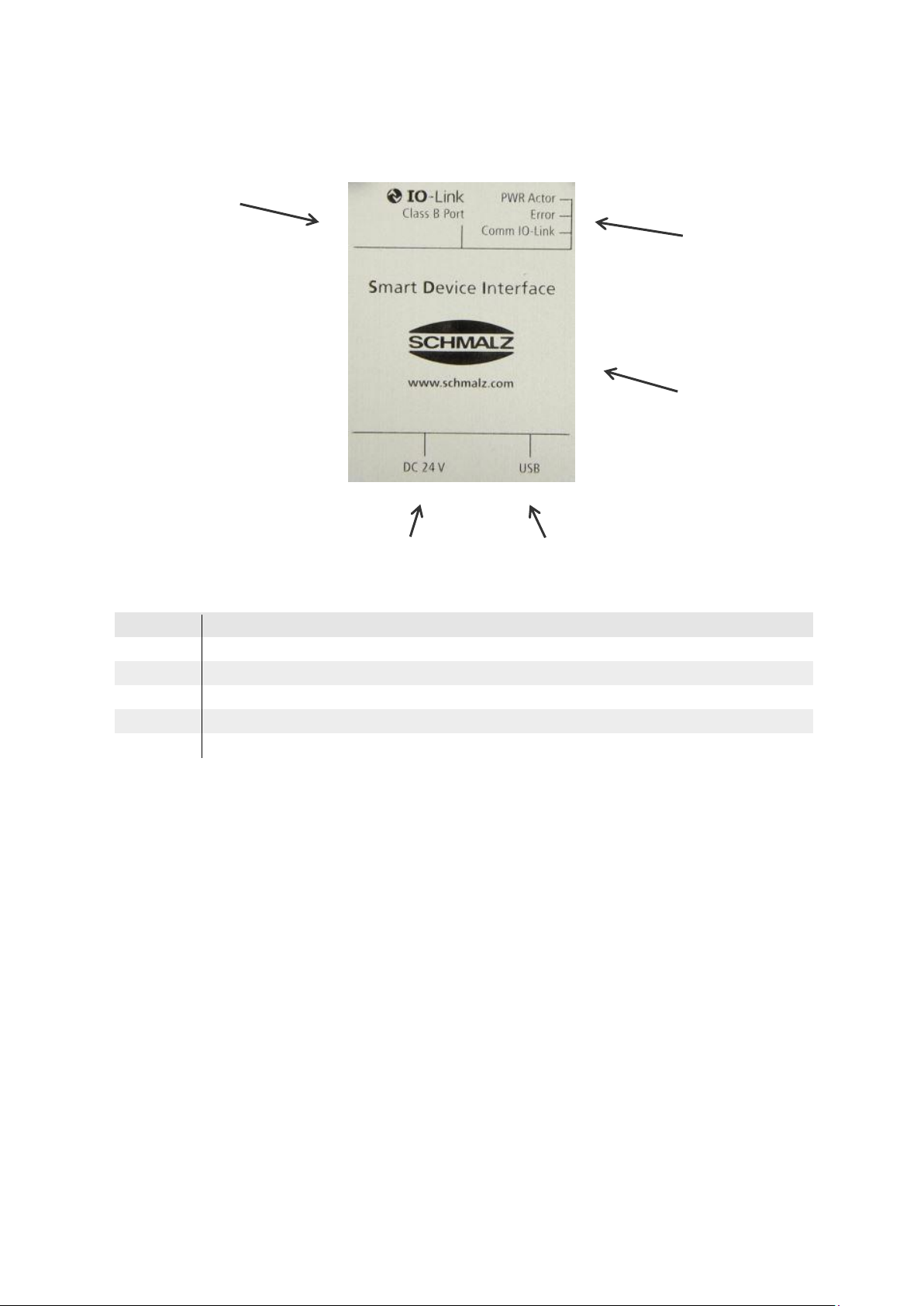
Item
Description
1
M12-Socket for IO-Link Port Class B (Connection for IO-Link-Device)
2
Status LEDs (location: lateral)
3
USB-Cable connection to Laptop
4
M12 Connection for power supply
5
Manufacturer
1 2 3 4 5
2.3 Frontview and Interfaces
CE marking, device type and order number are listed on the product label (see back side).
30.30.01.00953/01 www.schmalz.com EN | 7
Page 8
DESIGN AND FUNCTION
Item
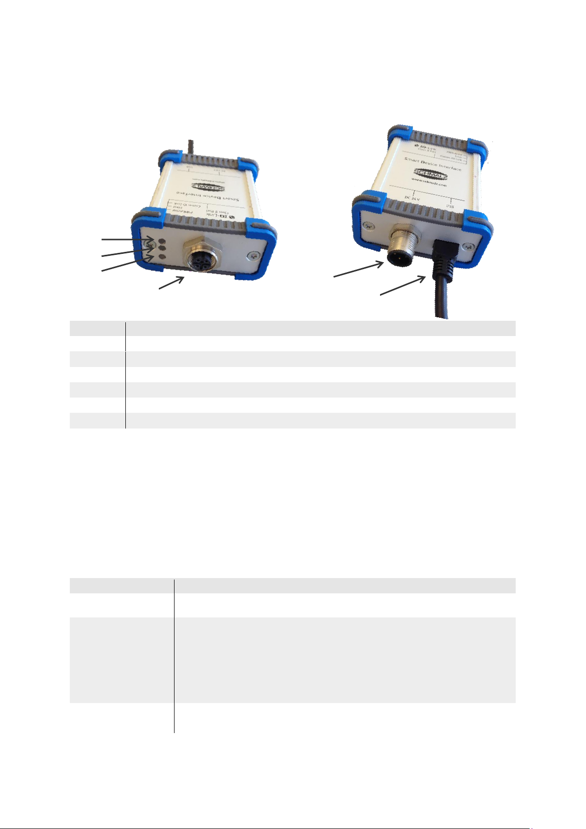
Description
1
Supply voltage DC 24 V, M12 connection for external Power Supply
2
USB A, connection to PC / Laptop
3
LED green: "communication IO-Link". LED yellow: “SIO – Mode”
4
LED red: "Error"
5
LED green: “Power on, Power supply connected”
6
M12 socket, connection for IO-Link device
Function display
Description
PWR
LED off No operation
Port1 (C/Q)
IO-Link display
LED green Flashing slowly No IO-Link connection
present
Lit Data exchange taking place
via the IO-Link connection
(Operate)
LED yellow SIO – Mode high
Error
LED red Error display Short circuit or
Data transfer error
1
2
3
4
5
6
3 Design and function
3.1 Design
3.2 Function
The SDI-USB serves as an interface between an IO-Link device and a Laptop or PC with a Windows
operating system. Together with the SDI-USB-HMI software program, IO-Link devices can be
operated, read out and parameterized..
3.3 Display elements
8 | EN www.schmalz.com 30.30.01.00953/01
Page 9
ELECTRICAL CONNECTION
CAUTION
Incorrect supply voltage
Damage to the device
►
If external power required, operate the SDI-USB with the mains power adapter
provided only
Establish all electrical connections before starting the software
Always connect the mains power adapter provided to the DC 24 V socket of the
SDI-USB and connect the mains power adapter to the supply voltage
Contact
Signal
Description
1
+5V
VBUS +5 V DC/500 mA
2
D-
Data–
3
D+
Data+
USB A
4
GND
Ground (0 V)
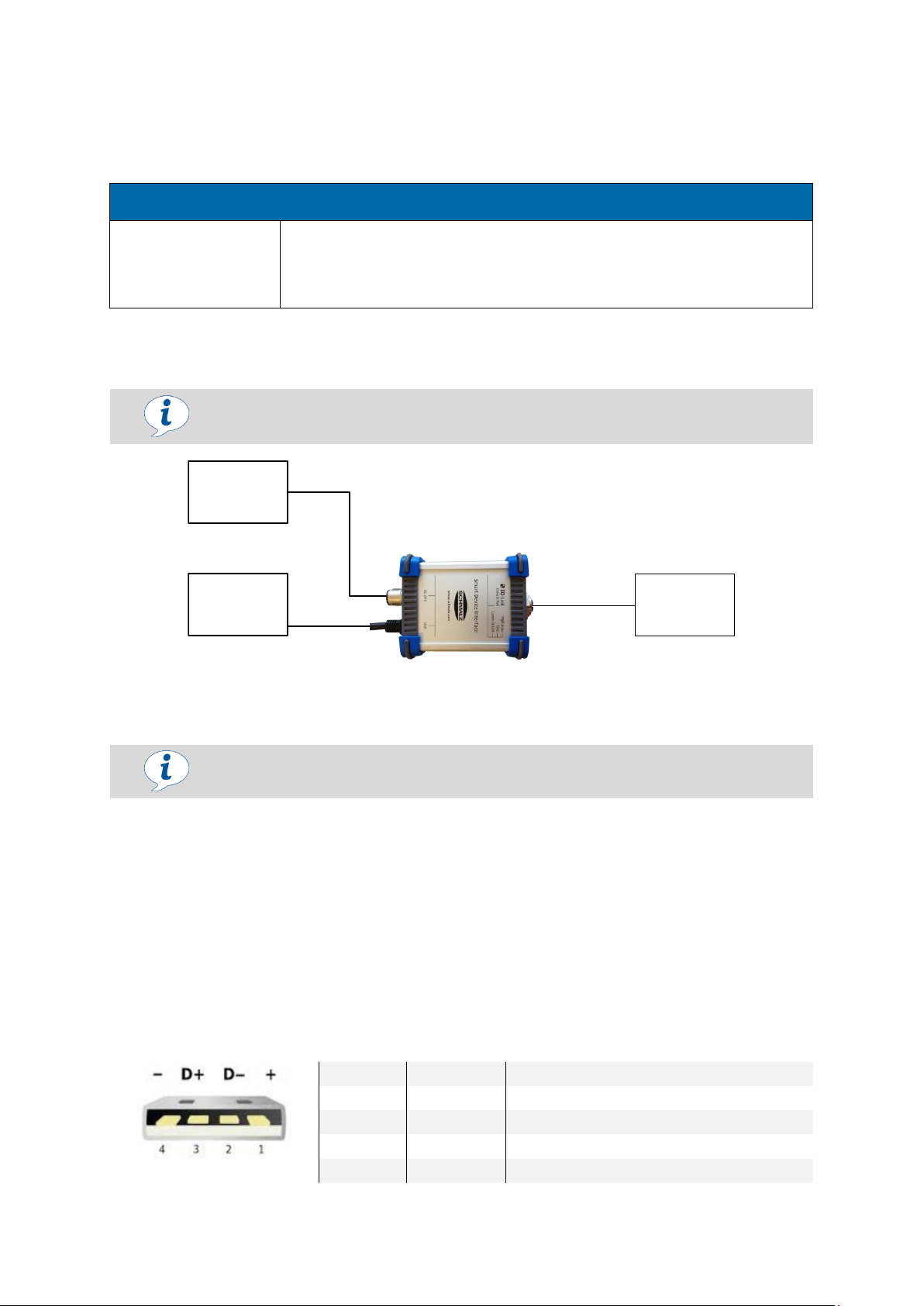
PC
SDI
IO-Link-
device
Power
supply
24V/1A
USB-Cable
M12-Cable
4 Electrical connection
4.1 Connecting the SDI-USB electrically
Ensure that there is no voltage
Connect the SDI-USB to the USB-Socket of the PC/Laptop
Connect the IO-Link device to the M12 socket of the SDI-USB via the M12 cable provided
4.1.1 Supply and interface
USB: PC connection (USB ≤ 500 mA corresponds to DC 24 V / 80 mA)
Socket: Connection of an external mains power adapter (DC 24 V / 1 A)
M12 socket, 5-pole, A-coded, with pin assignments of IO-Link Class B
* For devices with a power requirement higher than 1000mA on the actuator side a corresponding power supply must be used
Polarity reversal protection is ensured
4.2 USB connection diagram
30.30.01.00953/01 www.schmalz.com EN | 9
Page 10
TECHNICAL DATA
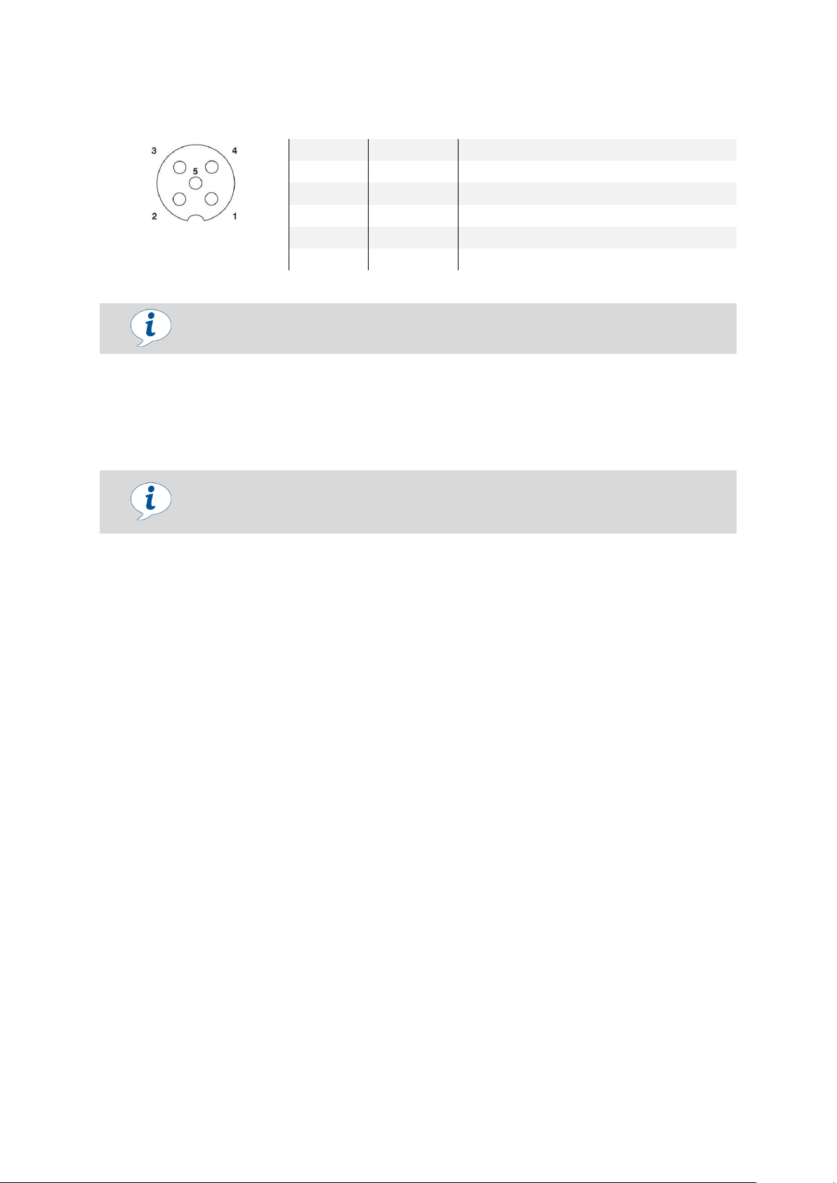
Contact
Signal
Description
1
+24V DC
Sensor supply voltage up to 80 mA
2
+24V DC
Actuator supply voltage up to 2000 mA *
3
0V
GNDS supply voltage
M12 socket, 5-pole
A-coded
4
Port1 (C/Q)
IO-Link 5 0V
GNDA supply voltage
The SDI-USB does not have potential separation between sensor and actuator
voltage
You can download, save and print the associated online data sheet with technical
data, dimensions and connection diagram of your SDI-USB from
www.schmalz.com.
4.3 IO-Link connection diagram
* For devices with a power requirement higher than 1000mA on the actuator side a corresponding power supply must be used
5 Technical data
Supply voltage DC 24 V Connection for the power supply provided
LED function display (yellow) "PWR/USB"
USB A PC connection via the USB cable provided
LED function display (green) "Port 1 (C/Q)"
LED function display (red) "Error"
M12 connector Connection IO-Link device
5.1 Ambient conditions
Protection class III
Ambient temperature range
o Operation 0 °C … +45 °C
o Storage 0 °C … +60 °C
Degree of protection IP 43
10 | EN www.schmalz.com 30.30.01.00953/01
Page 11

INSTALLING SOFTWARE
6 Installing software
6.1 Installing software
The SDI-USB operator software from Schmalz is required for parameterization of the IO-Link device
via the SDI-USB.
Admin-privileges are required to install the software.
6.2 Installation
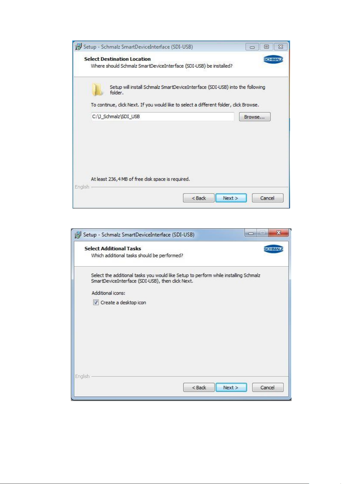
1. Start installation of the SDI-USB Operator Software via the "setup.exe" file. The following view
appears:
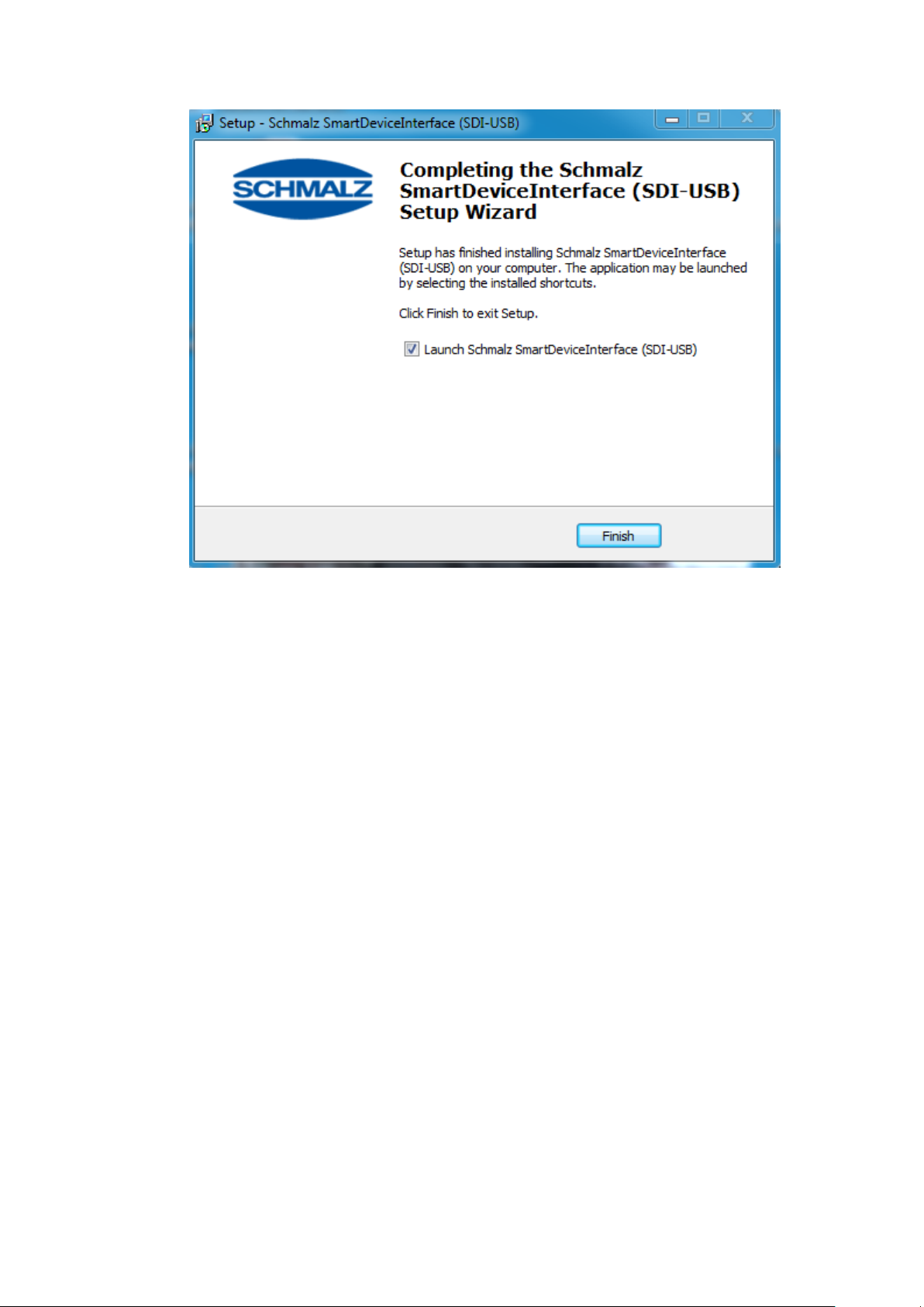
2. Install the program according to the installation wizard.
30.30.01.00953/01 www.schmalz.com EN | 11
Page 12

INSTALLING SOFTWARE
12 | EN www.schmalz.com 30.30.01.00953/01
Page 13
INSTALLING SOFTWARE
30.30.01.00953/01 www.schmalz.com EN | 13
Page 14

INSTALLING SOFTWARE
14 | EN www.schmalz.com 30.30.01.00953/01
Page 15
INSTALLING SOFTWARE
30.30.01.00953/01 www.schmalz.com EN | 15
Page 16

INSTALLING SOFTWARE
With
administrative
privileges
16 | EN www.schmalz.com 30.30.01.00953/01
Page 17
MAINTENANCE
Display
Possible Cause
Troubleshooting
Red LED "Error" is illuminated
Data transfer error
Transfer the data again
Short-circuit
1.) Disconnect device and
reconnect
2.) Replace the SDI-USB
CAUTION
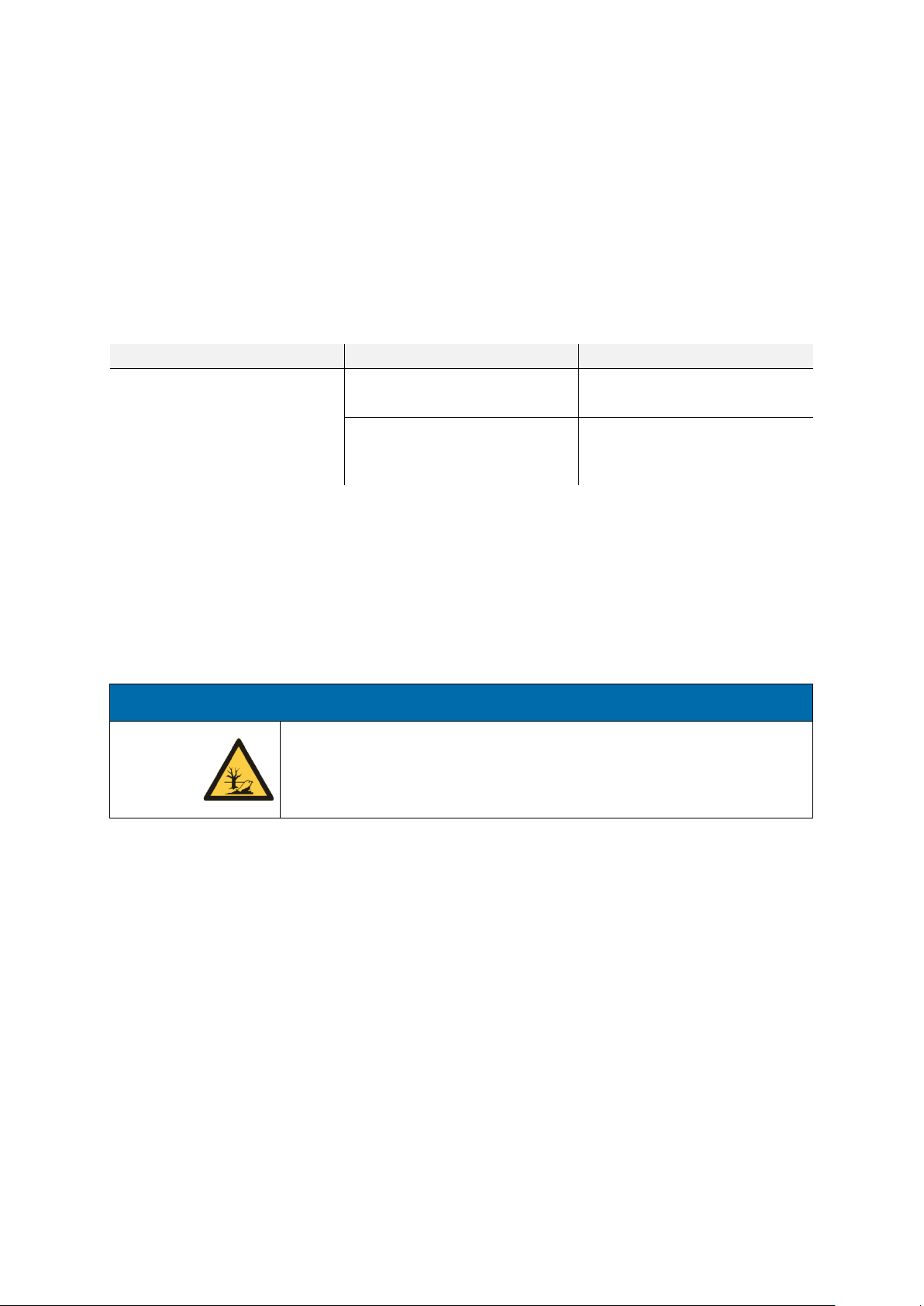
Improper disposal of replaced components
Environmental damage
►
Disposal according to country-specific guidelines
7 Maintenance
7.1 Cleaning
SCHMALZ devices are maintenance-free. Schmalz recommendation: check screw unions and plug
connections of the device at regular intervals.
7.2 Troubleshooting
7.3 Disposal
After being exchanged or after final decommissioning, components and assemblies are to be disposed
of in accordance with country-specific guidelines.
30.30.01.00953/01 www.schmalz.com EN | 17
Page 18
CONFORMITY DECLARATION
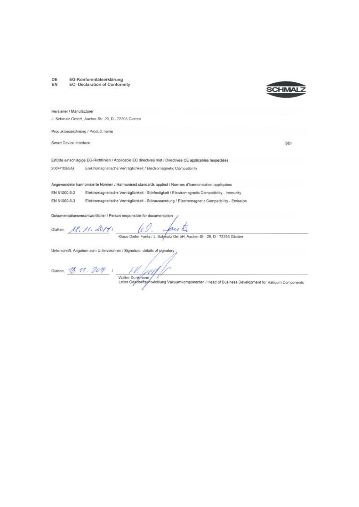
8 Conformity Declaration
18 | EN www.schmalz.com 30.30.01.00953/01
 Loading...