

Page 1
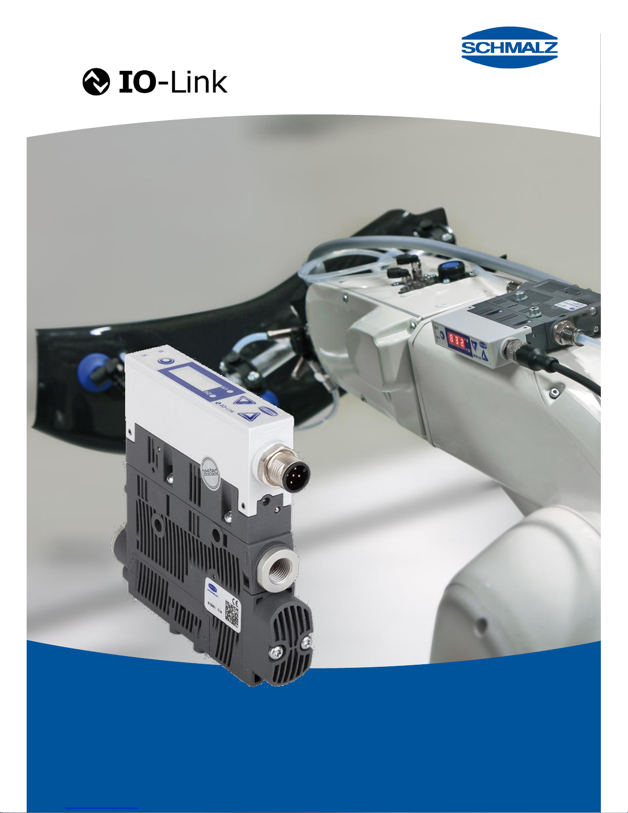
Innovative Vacuum for Automation
EN
SCPSi-2
Eco-Nozzle Technology
Operating instructions
30.30.01.00762
Page 2

SCHMALZ SCPSI - 2
CONTENTS
1 Safety Instructions ................................................................................................. 1-5
Important symbols ............................................................................................................................ 1-5
General safety instructions ............................................................................................................... 1-5
Intended use ..................................................................................................................................... 1-6
Installation and operation ................................................................................................................. 1-7
2 Product Overview ................................................................................................... 2-8
General description of functions ...................................................................................................... 2-8
Vacuum generation (picking up the workpiece) ............................................................................... 2-8
Blow-off (depositing the workpiece) ................................................................................................. 2-9
IO-Link .............................................................................................................................................. 2-9
Versions ............................................................................................................................................ 2-10
Ejector version PNP or NPN .......................................................................................................... 2-10
Electrical connection ...................................................................................................................... 2-10
Ejector design ................................................................................................................................... 2-11
Operating and display elements ..................................................................................................... 2-12
3 Description of Functions ..................................................................................... 3-14
Operating modes .............................................................................................................................. 3-14
Control concept for NO ejectors ..................................................................................................... 3-16
Control concept for NC ejectors ..................................................................................................... 3-16
General functions ............................................................................................................................. 3-17
Manual mode .................................................................................................................................. 3-17
Set-up mode ................................................................................................................................... 3-18
Monitoring the system vacuum ...................................................................................................... 3-18
Zero-point adjustment of the sensor (calibration) .......................................................................... 3-18
Control function .............................................................................................................................. 3-19
Deactivating the control shutoff function ........................................................................................ 3-19
Blow-off modes ............................................................................................................................... 3-20
Signal output .................................................................................................................................. 3-21
Selecting the vacuum unit .............................................................................................................. 3-21
Switch-off delay of the H2 component check signal ...................................................................... 3-22
ECO-Mode ..................................................................................................................................... 3-22
PIN for write protection ................................................................................................................... 3-23
Write protection with Device Access Locks .................................................................................... 3-23
Reset to factory settings ................................................................................................................. 3-24
Counter ........................................................................................................................................... 3-24
Voltage monitoring ......................................................................................................................... 3-25
Evaluating the inlet pressure .......................................................................................................... 3-25
Setting the blow-off volume flow .................................................................................................... 3-26
Production setup-profiles ................................................................................................................ 3-26
Condition Monitoring [CM] .............................................................................................................. 3-27
Monitoring the valve switching frequency ...................................................................................... 3-27
Monitoring the control threshold ..................................................................................................... 3-27
Monitoring the evacuation time ...................................................................................................... 3-28
Monitoring leakage ......................................................................................................................... 3-28
Monitoring the dynamic pressure ................................................................................................... 3-28
Evaluating the leakage level .......................................................................................................... 3-29
Measurement of the evacuation time t0 .......................................................................................... 3-29
Measurement of the evacuation time t1 .......................................................................................... 3-29
Page 3

SCHMALZ SCPSI - 2
Autoset ........................................................................................................................................... 3-29
Energy monitoring [EM] ................................................................................................................... 3-30
Percentual air consumption measurement..................................................................................... 3-30
Absolute air consumption measurement ........................................................................................ 3-30
Energy consumption measurement ............................................................................................... 3-30
Predictive Maintenance [PM] ........................................................................................................... 3-31
Measurement of the leakage .......................................................................................................... 3-31
Measurement of the dynamic pressure .......................................................................................... 3-31
Quality assessment ........................................................................................................................ 3-31
Performance calculation ................................................................................................................. 3-31
Diagnostic buffer .............................................................................................................................. 3-32
EPC data buffer ................................................................................................................................. 3-32
4 Operating and Menu Concepts ........................................................................... 4-33
Vacuum display ................................................................................................................................ 4-33
Individual functions.......................................................................................................................... 4-33
Supply voltage ................................................................................................................................ 4-33
Operating mode display ................................................................................................................. 4-34
Error display ................................................................................................................................... 4-34
Main menu ......................................................................................................................................... 4-35
Setting the parameters in the main menu ...................................................................................... 4-36
Zero-point adjustment (calibration) ................................................................................................ 4-36
Configuration menu ......................................................................................................................... 4-37
Setting the parameters in the configuration menu ......................................................................... 4-39
Entering the PIN ............................................................................................................................. 4-39
Executing the “reset to factory settings” function ........................................................................... 4-39
System menu .................................................................................................................................... 4-40
Viewing data in the system menu .................................................................................................. 4-40
Viewing the counters ...................................................................................................................... 4-40
Software version ............................................................................................................................. 4-41
Serial number ................................................................................................................................. 4-41
Article number ................................................................................................................................ 4-41
5 Operating Mode .................................................................................................... 5-42
SIO operating mode ......................................................................................................................... 5-42
Overview......................................................................................................................................... 5-42
Mounting ......................................................................................................................................... 5-43
Pneumatic connection .................................................................................................................... 5-43
Electrical connection ...................................................................................................................... 5-44
Pin assignment of the connection plug .......................................................................................... 5-45
Projektieren .................................................................................................................................... 5-46
Start of operations .......................................................................................................................... 5-46
Warnings and errors ....................................................................................................................... 5-47
IO-Link mode ..................................................................................................................................... 5-48
Overview......................................................................................................................................... 5-48
Mounting ......................................................................................................................................... 5-49
Pneumatic connection .................................................................................................................... 5-49
Electrical connection ...................................................................................................................... 5-50
Pin assignment of the connection plug .......................................................................................... 5-51
Project planning .............................................................................................................................. 5-51
Process data .................................................................................................................................. 5-53
Parameter data ............................................................................................................................... 5-54
Configuration server ....................................................................................................................... 5-54
Start of operations .......................................................................................................................... 5-55
System status light ......................................................................................................................... 5-60
Warnings and errors ....................................................................................................................... 5-60
Page 4

SCHMALZ SCPSI - 2
EPC-Values in the Process data .................................................................................................... 5-61
6 Maintenance .......................................................................................................... 6-62
General maintenance ....................................................................................................................... 6-62
Exterior soiling ................................................................................................................................ 6-62
Silencer........................................................................................................................................... 6-62
press-in Screens ............................................................................................................................ 6-62
Warranty, spare parts and wearing parts ...................................................................................... 6-62
Spare and wearing parts ................................................................................................................ 6-63
Troubleshooting ............................................................................................................................... 6-63
Accessories ...................................................................................................................................... 6-63
7 Technical Data ...................................................................................................... 7-64
Electrical parameters ....................................................................................................................... 7-64
Display parameters .......................................................................................................................... 7-65
Mechanical data ................................................................................................................................ 7-65
General parameters ....................................................................................................................... 7-65
Materials used ................................................................................................................................ 7-66
Mechanical parameters .................................................................................................................. 7-66
Dimensions ..................................................................................................................................... 7-67
Pneumatic circuit diagrams ............................................................................................................ 7-68
Overview of display symbols .......................................................................................................... 7-69
Factory settings ................................................................................................................................ 7-71
8 Conformity Declaration ........................................................................................ 8-72
Page 5
SCHMALZ SCPSI - 2
1-5
1 SAFETY INSTRUCTIONS
IMPORTANT SYMBOLS
This symbol indicates important information and instructions.
Caution!
This symbol indicates a potentially dangerous situation.
If it is not avoided, slight or minor injuries may result.
Danger!
This symbol indicates an immediate hazard.
If it is not avoided, death or serious injuries may result.
GENERAL SAFETY INSTRUCTIONS
These operating instructions contain important information on using the ejector. Please
read the operating instructions thoroughly and keep them for later reference.
Never look into any open or closed vacuum vents (e.g. vacuum connections or suction pads).
Serious injuries could occur as a result. Eyes can be sucked in.
Compressed air can cause closed containers to explode. A vacuum can cause closed
containers to implode.
The ejector may only be operated with a silencer. Never look into the exhaust air jet of
the silencer.
The ejector emits noise. We recommend wearing ear protection.
This device is not intended for use with hazardous dust, oil mist, vapors or aerosols,
etc. If drawn in, these materials will enter the exhaust air and may result in poisoning.
Use only the connections, mounting holes and attachment materials that have been
provided.
Carry out mounting and removal only when the device is in an idle, depressurized state.
No person may sit or stand in the area in which the load is to be transported.
No person may sit or stand in the danger zone while the machine or system is in auto-
matic mode.
Components may be installed by trained specialist personnel only.
Page 6

SCHMALZ SCPSI - 2
1-6
Specialist personnel must be familiar with current safety rules and requirements. For
example, these apply to the use of components such as solenoid valves and pressure
switches as well as to controllers used in devices, machines and systems.
Specialist personnel must also be familiar with the system’s control concept. In particu-
lar, they must be familiar with the system’s redundant control components and feed-
back signals.
INTENDED USE
The ejector is designed to generate a vacuum for gripping and transporting objects when
used in conjunction with suction pads. Neutral gases in accordance with EN 983 are approved as evacuation media. Neutral gases include air, nitrogen and inert gases (e.g. argon, helium and neon). Aggressive gases or media such as acids, acid fumes, bases, biocides, disinfectants or detergents are not permitted.
The ejector is not suitable for transporting or sucking through liquids or bulk material such as granulates.
Personal injury or damage to the ejector may occur.
Page 7
SCHMALZ SCPSI - 2
1-7
INSTALLATION AND OPERATION
For safe installation and trouble-free operation, please observe and comply with the following points:
The ejector may only be operated using power supply units with protected
extra-low voltage (PELV). The system must incorporate safe electrical cutoff of the power supply in compliance with EN60204.
Do not operate the ejector in environments where there is a risk of
explosion.
Risk of fire and explosion.
Output signals (discrete signals as well as IO-Link signals) can change
when the power supply is switched on or the M12 connectors are plugged
in. Depending on the function of the machine/system, this can result in
serious personal injury or damage to the equipment.
The device may not be operated outside its specified performance limits.
Doing so may cause it to malfunction or be destroyed.
During installation and maintenance, make sure that the ejector is disconnected
and depressurized and that it cannot be switched on again without authorization.
Personal injury or damage to the ejector may occur.
Protect the ejector from damage at all times.
No modifications may be made to the ejector.
Opening the ejector will damage the “tested” labels. This voids the warranty.
Connection symbols and labels are located on the ejector.
These must be observed.
Only the intended connections may be used.
Pneumatic and electrical line connections must be securely connected and attached to
the ejector.
The ejector may be installed in any position.
If these instructions are not observed, malfunctions, material damage and serious injury
– including fatal injury – may result.
If the ejector is no longer operative, the components must be disposed of in an ecologi-
cally sound manner.
Page 8

SCHMALZ SCPSI - 2
2-8
2 PRODUCT OVERVIEW
GENERAL DESCRIPTION OF FUNCTIONS
VACUUM GENERATION (PICKING UP THE WORKPIECE)
The ejector is designed for vacuum handling of parts in combination with suction systems.
The Venturi nozzle is activated and deactivated via the suction signal input. In the NO ver-
sion, the Venturi nozzle is deactivated when the suction input signal is present. In the NC
version, the Venturi nozzle is activated when the suction input signal is present.
An integrated sensor records the vacuum generated by the Venturi nozzle. This is evaluated by an electronics system and appears on the display. The measured value serves as
the basis for the air saving function, switching the output and the many analysis functions
of the energy process control system.
The ejector has an integrated air-saving function. The ejector automatically regulates the
vacuum while in suction mode. The electronics system switches the Venturi nozzle off
when the switching point H1 set by the user is reached.
If small volumes are to be evacuated, the set switching point H1 might be
exceeded considerably before the vacuum is switched off. This system behavior
does not constitute an error.
When objects with dense surfaces are picked up, the integrated non-return valve prevents
the vacuum from dropping. If leakage causes the system vacuum to drop below the switching point H1-h1, the Venturi nozzle is switched on again.
The supply voltage is monitored by the electronics system. If the supply voltage falls below
approx. 19.2 V, this is indicated by an error message. It cannot be ensured that the ejector
will operate as intended below this voltage threshold.
The supply voltage’s maximum permitted upper limit of approx. 26.4 V is also monitored.
The display will indicate any value in excess of this limit.
Page 9

SCHMALZ SCPSI - 2
2-9
BLOW-OFF (DEPOSITING THE WORKPIECE)
In blow-off mode, the vacuum circuit of the ejector is supplied with compressed air. This
ensures that the vacuum drops quickly, depositing the workpiece quickly as well. Blow-off
mode can be controlled externally or internally.
When controlled externally, blow-off mode is activated by the “blow-off” signal input.
When controlled internally (automatic blow-off), the blow-off valve is actuated for a defined
period after suction mode is exited.
With the externally controlled automatic blow-off, the “Blow-off” valve is activated for a set
amount of time once the “Blow-off” signal input is received.
The ejector also has a manual mode. In this mode, suction and blow-off can be
controlled using the keys on the ejector’s foil keypad. See the “Manual mode”
section for more details.
IO-LINK
The ejector can be operated in IO-Link mode to enable intelligent communication with a
controller.
The ejector’s parameters can be set remotely using IO-Link mode. The energy and process control (EPC) function is also available in IO-Link mode.
Energy and process control (EPC) is divided into 3 modules:
Condition monitoring (CM): Condition monitoring to increase system availability
Energy monitoring (EM): Energy monitoring to optimize the vacuum system’s energy
consumption
Predictive maintenance (PM): Predictive maintenance to increase the performance and
quality of the gripper systems
Page 10

SCHMALZ SCPSI - 2
2-10
VERSIONS
Each ejector has a specific item designation (e.g. SCPSi-2-07-G2-NO-M12).
The item designation can be broken down as follows:
Type
Perfomance
class
Pneumatic
connection
Idle position
Electrical
connection
SCPSi
2-07
2-09
2-14
G2
(2x G1/8“)
S2 (8/6mm)
S4 (6/4mm)
NO
Normally open
NC
Normally closed
M12
1xM12, 5-pin
The most important components are described below.
EJECTOR VERSION PNP OR NPN
The behavior of the ejector’s electrical inputs and output can be adjusted on the device
and therefore does not depend on the version.
The ejectors are factory set to PNP.
ELECTRICAL CONNECTION
The electrical connection is established using a 5-pin M12 plug that supplies the ejector
with voltage, and contains the two input signals and the output signal. The inputs and output are not electrically isolated from one another.
Page 11
SCHMALZ SCPSI - 2
2-11
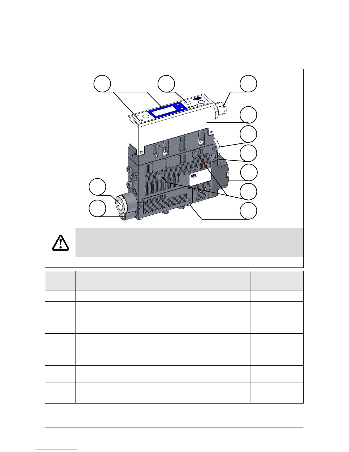
EJECTOR DESIGN
3
4
1 5
6
8
7
9
10
2
10
Only screw unions with cylindrical G-threads can be used at pos. 4 and pos. 8.
We recommend using washers on the mounting holes.
Do not look into the exhaust outlet (compressed air) during operation
Position
Description
Max. tightening
torque
1
Process state display: suction / blow-off / vacuum value
2 Controls
3 Blow-off valve screw
4 G1/8" vacuum connection (label: 2 [V])
4 Nm
5
M12 electrical connection
Hand-tight
6
Controller
7
Mounting holes
2 Nm
8
Compressed air connection
G1/8" in H version (label: 1 [P])
4 Nm
9
Silencer cover
0,5 Nm
10
Exhaust outlet (label 3 and Silencer cover)
Page 12
SCHMALZ SCPSI - 2
2-12
OPERATING AND DISPLAY ELEMENTS
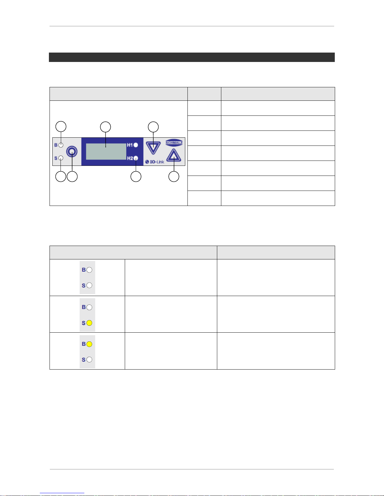
The 3 keys, the three-digit display and 4 additional LEDs ensure simple operation of the
ejector.
Position
Description
7
1 5
6 3 2 4
1
Display
2
LEDs for threshold values H1/H2
3
MENU button
4
UP button
5
DOWN button
6
LED Process state „Suction“
7
LED Process state „Blow-off“
LEDS PROCESS STATE
The “Suction” and “Blow-off” process states are each assigned an LED.
Process state LEDs
Ejector status
LEDs are both off
No suction on ejector
Suction LED
is continuously lit
Ejector is in suction state or being controlled
Blow-off LED
is continuously lit
Ejector blows off
Page 13
SCHMALZ SCPSI - 2
2-13
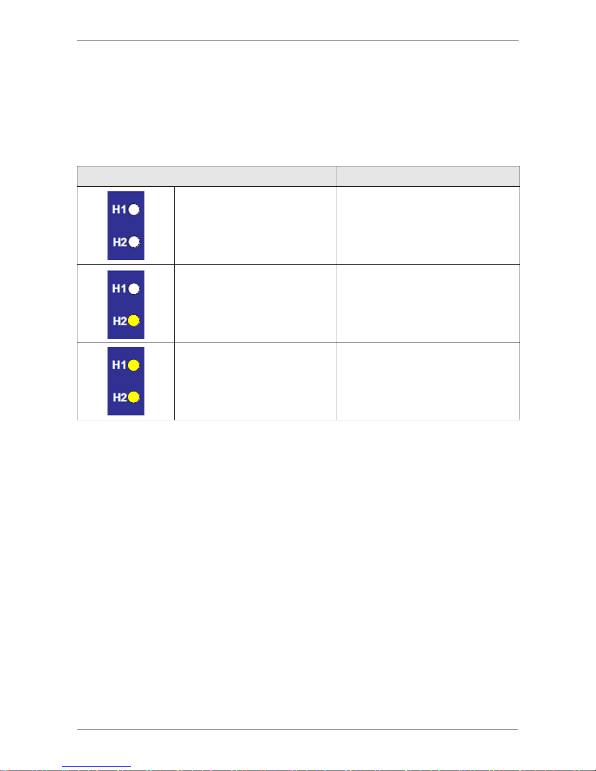
LEDS FOR THRESHOLD VALUES H1/H2
During conventional suctions cycles, the LEDs shows the current level of the system vacuum relative to the switching points H1 and H2. Their display behavior is independent of
the switching functions or assignment of the output; it is also independent of whether the
condition monitoring function is active.
.
Threshold value LEDs
Ejector status
LEDs are both off
Rising vacuum:
Vacuum < H2
Falling vacuum:
Vacuum < (H2-h2)
H2 LED is continuously lit
Rising vacuum:
Vacuum > H2 and < H1
Falling vacuum:
Vacuum > (H2-h2) and < (H1-h1)
LEDs are both continuously lit
Rising vacuum:
Vacuum > H1
Falling vacuum:
Vacuum > (H1-h1)
Page 14
SCHMALZ SCPSI - 2
3-14
3 DESCRIPTION OF FUNCTIONS
OPERATING MODES
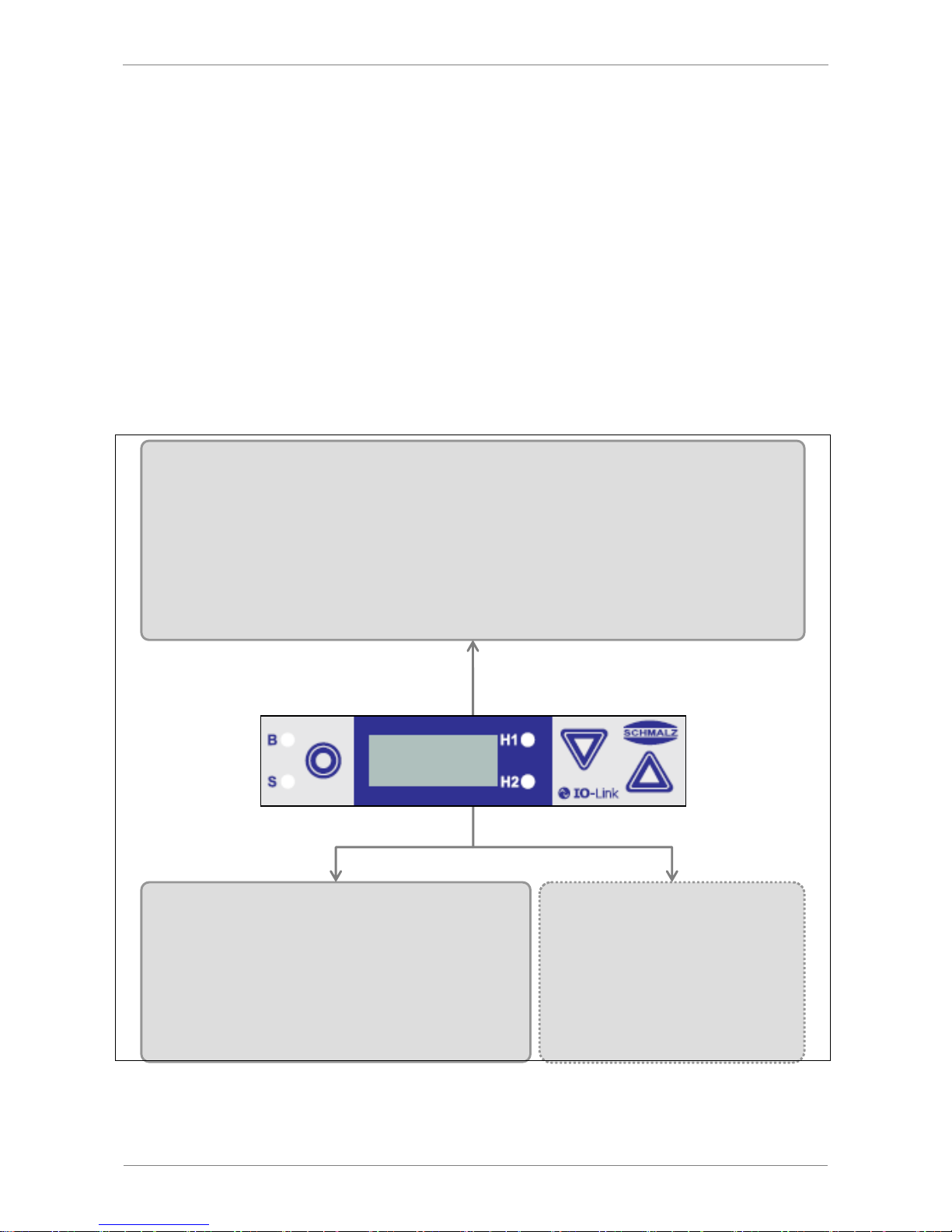
The ejectors are differentiated according to their start position when in the idle state: NO
(normally open) and NC (normally closed).
When the ejector is connected to the power supply, the ejector is in automatic mode and
ready for operation. This is the normal operating mode, in which the ejector is operated by
the system controller. A differentiation is made between SIO mode and IO-Link mode.
In addition to automatic mode, you can also use the keys on the ejector to switch to manual mode using the buttons on the foil keypad.
Parameterization of the ejector is always performed in automatic mode.
A U T O M A T I C – M O D E
P A R A M E T R I Z A T I O N
M A N U A L M O D E
Page 15
SCHMALZ SCPSI - 2
3-15
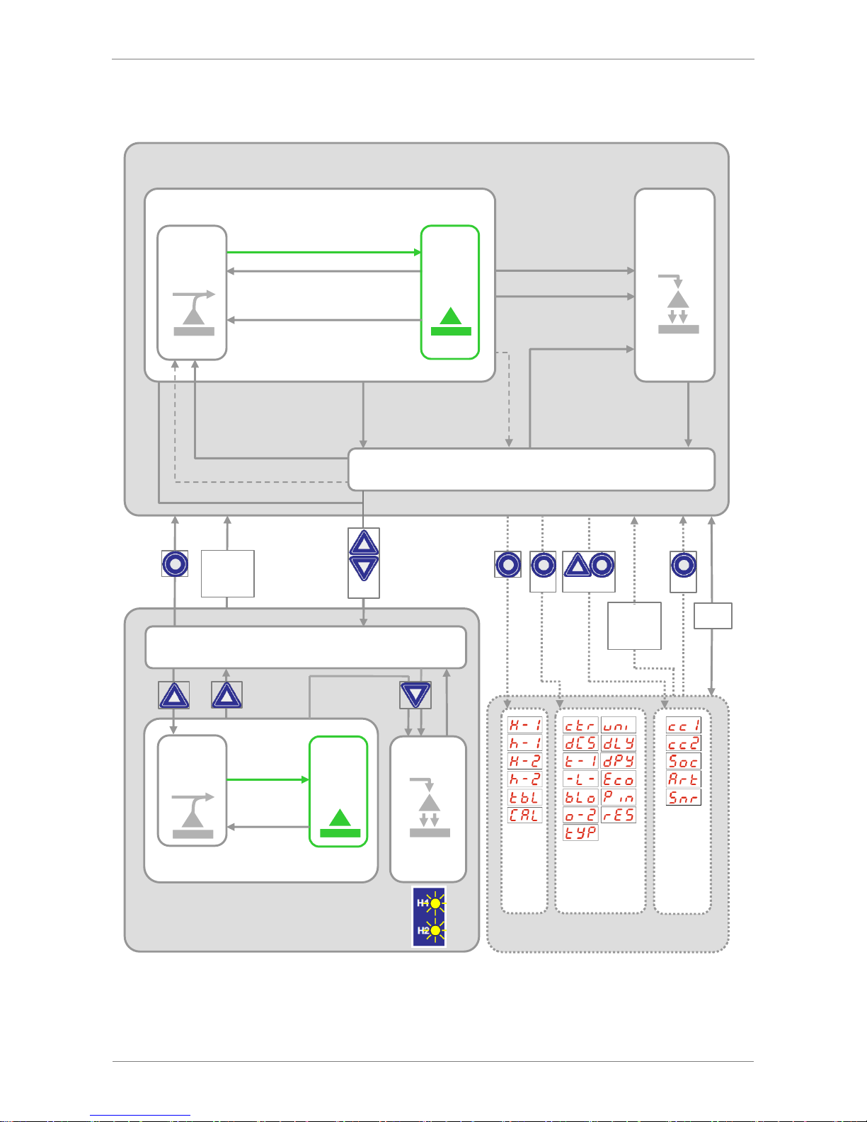
A U T O M A T I C – M O D E
P A R A M E T E R I Z A T I O N
Main-
menu
Configuration-
menu
Suction OFF
Auto blow-off
NC, NO:
[bLo = J-t]
Blow-off ON
NC, NO:
IN2 = on
M A N U A L M O D E
Blow-off
Suction ON
NC : IN1 = on
NO : IN1 = off
Suction OFF
NC : IN1 = off
NO : IN1 = on
Blow-off OFF
NC, NO:
IN2 = off
Pneumatically OFF
Counter-
menu
Pneumatically OFF
NC:
Power
failure
NO: Power failure
Suction
Venturi-
nozzle
active
Venturi-
nozzle
inactive
Vacuum
H1
Vacuum
< H1-h1
Air-saving function
Blow-off
Suction
Air-saving function [ctr = on]:
Vacuum H1
Vacuum < H1-h1
Valve protection funktion:
Switching frequency > 6/3s
Venturi-
nozzle
active
Venturi-
nozzle
inactive
> 3 s
> 3 s
IO-Link
> 3s
> 2 s
No
button
> 2 min
Change in
External
signal
Page 16
SCHMALZ SCPSI - 2
3-16
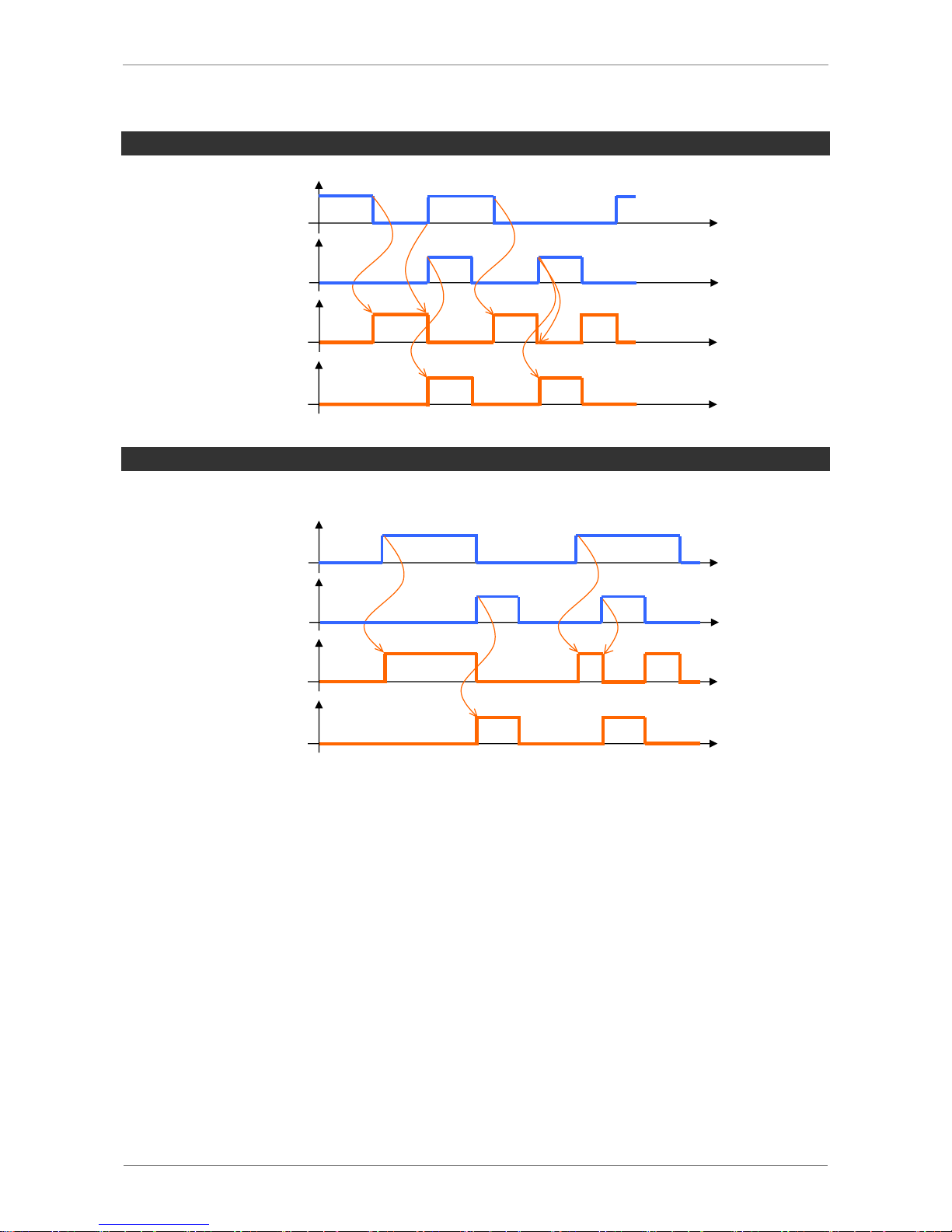
CONTROL CONCEPT FOR NO EJECTORS
1
0
0 bar
- p
1
0
0 bar
p
„ Suction“ [IN1]
„ Blow-off“ [IN2]
„Suction“ Mode
„Blow-off“ Mode
CONTROL CONCEPT FOR NC EJECTORS
1
0
0 bar
- p
1
0
0 bar
p
„ Suction“ [IN1]
„ Blow-off“ [IN2]
„Suction“ Mode
„Blow-off“ Mode
Page 17
SCHMALZ SCPSI - 2
3-17
GENERAL FUNCTIONS
MANUAL MODE
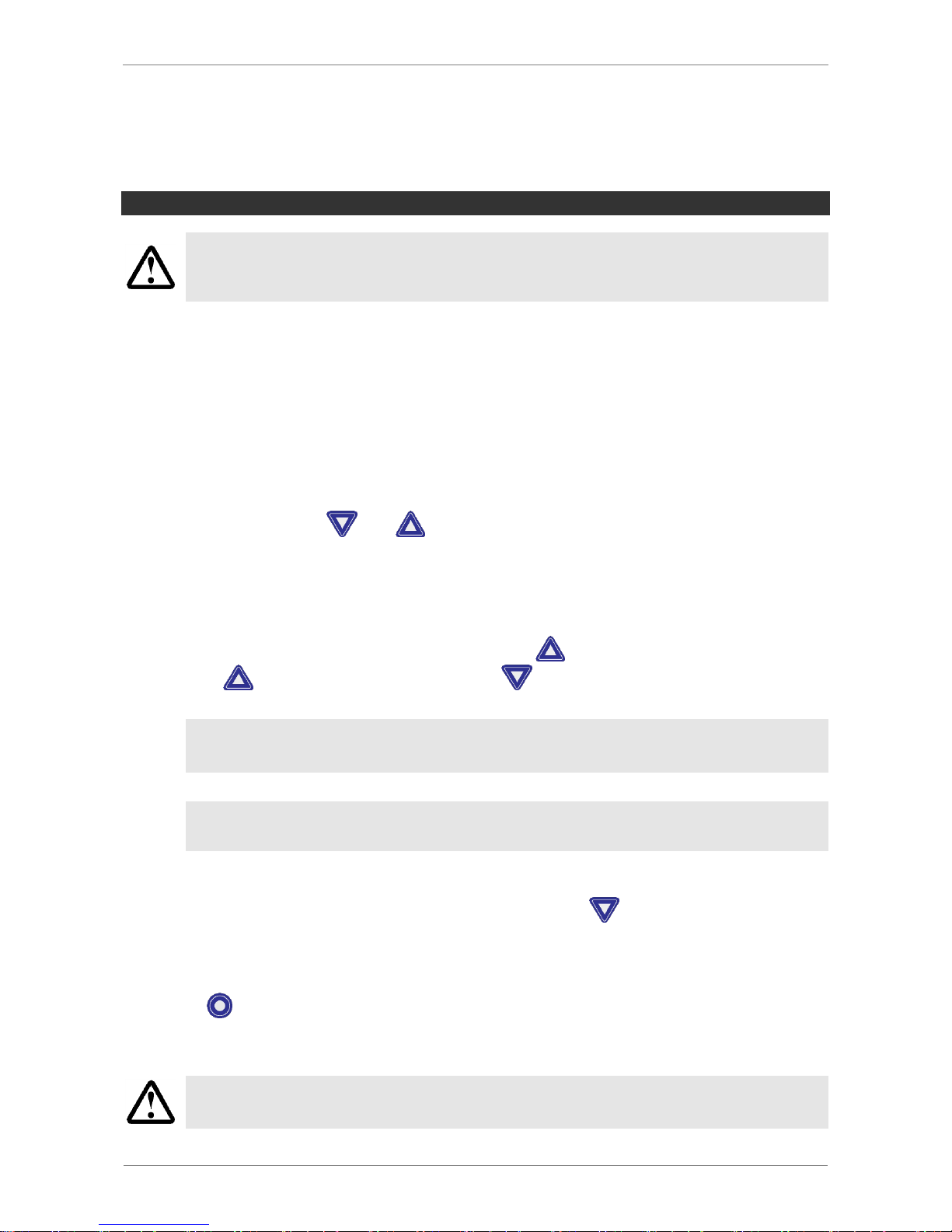
The output signals may change during set-up in manual mode.
Ensure that the machine or system does not start moving as a result.
Personal injury or damage to the ejector could result.
In manual mode, the “Suction” and “Blow-off” ejector functions can be controlled independently of the higher-level controller using the buttons on the operating panel.
In this operating mode, the H1 and H2 LEDs both flash.
Because the valve protection function is deactivated in manual mode, this function can be
used to locate and rectify leaks in the vacuum circuit.
ACTIVATING MANUAL MODE
Activate manual mode as follows:
Press and hold the and buttons together for more than 3 seconds.
During activation, [-M-] will appear.
When manual mode is activated, the current process state will initially be maintained.
MANUAL SUCTION
In manual mode, suction is activated by pressing the button. Exit suction mode by
pressing the
button again or by pressing the button.
If the air-saving function is activated ([ctr=on] or [ctr=ONS]), this is also activated in manual mode.
The valve protection function is not active in manual mode.
MANUAL BLOW-OFF
Blow-off mode is activated in manual mode by pressing the button. This mode remains
active as long as the button is pressed.
DEACTIVATING MANUAL MODE
Press the key to exit manual mode.
The operating mode will also be exited if the status of the external signal inputs changes.
This automatic exiting of manual mode due to changes in external signals can
cause the object being handled to move (due to suction or blow-off).
Page 18

SCHMALZ SCPSI - 2
3-18
SET-UP MODE
Similar to manual mode, set-up mode can be used to locate and rectify leaks in the vacuum circuit because the valve protection function is deactivated and because the control
function is not deactivated even if the control frequency increases.
In this operating mode, the H1 and H2 LEDs both flash.
Setup mode is switched on and off using the process data output (PDO). The suction and
blow-off process bits always have priority.
This function is only available in IO-Link mode.
MONITORING THE SYSTEM VACUUM
Every ejector has an integrated sensor for monitoring the current system vacuum. The vacuum level provides information on the process and has an effect on the following signals
and parameters:
Threshold value LED H1
Threshold value LED H2
Signal output H2
Vacuum analog value
Process data bits H1
Process data bits H2
The threshold values and the corresponding hysteresis values can be set under the menu
items [H-1], [h-1], [H-2] and [h-2] or via IO-Link.
ZERO-POINT ADJUSTMENT OF THE SENSOR (CALIBRATION)
Because the production conditions for the internally integrated sensor can vary, we
recommend calibrating the sensor once it is installed in the ejector.
The pressure circuit of the system must be ventilated to ambient pressure before a zeropoint adjustment can be made to the pressure sensor.
The zero point can only be shifted within a range of 3% from the end value of
the measurement range.
If the permissible limit of 3% is exceeded, the [E3] error code is shown in the
display.
The function for zero-point adjustment of the sensor is performed in the basic menu under
[CAL] or using IO-Link.
Page 19

SCHMALZ SCPSI - 2
3-19
CONTROL FUNCTION
With this function, the ejector allows you to save compressed air or prevent a too powerful
vacuum from being generated. Vacuum generation is interrupted once the configured
threshold value H1 is reached. If leakage causes the vacuum to fall below the hysteresis
threshold H1-h1, vacuum generation resumes.
The following operating modes can be set for the control function in the configuration
menu under the [ctr] menu item or via IO-Link.
NO CONTROL (CONTINUOUS SUCTION)
The ejector produces continuous suction with maximum power. This setting is recommended for very porous workpieces, which would otherwise cause the vacuum generator
to switch on and off continually due to the high rate of leakage.
The control function setting for this operating mode is [oFF].
This setting ([ctr = oFF]) is only possible when control shutoff is deactivated
[dCS = oFF].
CONTROL
The ejector switches off the vacuum generator when the threshold H1 is reached and switches it back on when the vacuum falls below the threshold H1-h1. This setting is particularly recommended for suction-tight workpieces.
The control function setting for this operating mode is [on].
CONTROL WITH LEAK MONITORING
This operating mode is the same as the previous mode, with the addition that the leakage
rate within the system is measured and compared to the configurable limit value [-L-]. If
the actual leakage rate exceeds the limit value more than twice in succession, the control
function is deactivated and the ejector switches to continuous suction.
In this mode, the control function should be set to [onS]
When the [onS] function is activated, [-L-] is activated in the configuration
menu.
DEACTIVATING THE CONTROL SHUTOFF FUNCTION
With this function, the automatic control shutoff caused by condition monitoring functions
can be deactivated.
The function can be set in the configuration menu under the [dCS] menu item or via IOLink.
Page 20

SCHMALZ SCPSI - 2
3-20
If the function [dCS = oFF] is selected, the ejector switches to continuous suction mode if
the leakage rate and the valve switching frequency are too high.
With the [dCS = on] setting, continuous suction is deactivated and the ejector continues
in control mode despite high leakage and a control frequency greater than 6/3 s.
If the control shutoff function is deactivated [dCS = on], the suction valve may
be switched very frequently.
This can destroy the ejector.
The setting [dCS = on] is only possible when the control function
[ctr = on] or [ctr = onS] is set.
In cases of undervoltage or power failure, the ejector switches to continuous
suction according to the particular ejector version (NO/NC/IMP), even if conti-
nuous suction was deactivated with the [dCS = on] setting.
BLOW-OFF MODES
This function is used to switch among the three blow-off modes.
The function can be set in the configuration menu under the [bLo] menu item or via IO-
Link.
EXTERNALLY CONTROLLED BLOW-OFF
The blow-off valve is controlled directly via the blow-off signal input. The ejector switches
to blow-off mode for as long as the signal is present.
The blow-off function setting for this operating mode is [-E-].
INTERNALLY TIME-CONTROLLED BLOW-OFF
The blow-off valve is controlled automatically for the time period [tbL] after the ejector
exits suction mode. This function makes it possible to save an output on the controller.
The blow-off function setting for this operating mode is [I-t].
The “Blow-off” mode can still be activated in [I-t] mode using the “Blow-off” signal input.
EXTERNALLY TIME-CONTROLLED BLOW-OFF
The blow-off pulse is controlled externally via the blow-off input. The blow-off valve is controlled for the configured time [tbL]. A longer input signal does not increase the blow-off
duration.
The blow-off function setting for this operating mode is [E-t].
Page 21

SCHMALZ SCPSI - 2
3-21
The length of the blow-off time [tbL] is set in the main menu. This menu item is
hidden in the [-E-] operating mode.
The number displayed indicates the blow-off time in seconds. Blow-off times
from 0.10 s to 9.99 s can be set.
SIGNAL OUTPUT
The ejector has a signal output. The signal output can be configured using the corresponding menu item.
OUTPUT FUNCTION
The signal output can be switched between [no] (normally open) and [nc] (normally
closed).
You can switch it in the configuration menu using the [o-2] menu item, or set it using the
IO-Link.
The function of the switching threshold H2/h2 (component check) is assigned to the OUT 2
signal output.
OUTPUT TYPE
The output type can be used to switch between PNP and NPN.
The signal inputs are also configured with this function.
The outputs/inputs can be switched using the [tYP] menu item in the configuration menu,
or via IO-Link.
SELECTING THE VACUUM UNIT
This function can be used to select the units for the displayed vacuum values from the
following three units.
The function can be set in the configuration menu under the [uni] menu item or via IOLink.
BAR
The vacuum values are displayed in mbar.
The setting for these units is [-bA].
PASCAL
The vacuum values are displayed in kPa.
The setting for these units is [-PA].
Page 22

SCHMALZ SCPSI - 2
3-22
INCH OF HG
The vacuum values are displayed in inHg.
The setting for this unit is [-iH].
The function can be set using the configuration menu under the menu item [uni] or can be
set via IO-Link.
Selection of the vacuum unit only affects the display of the ejector. The units of
the parameters that can be accessed via IO-Link are not affected by this setting.
SWITCH-OFF DELAY OF THE H2 COMPONENT CHECK SIGNAL
You can use this function to set a switch-off delay for the H2 component check signal. This
can be used to handle short drops in the vacuum circuit.
The length of the switch-off delay is set for both outputs together via the [dlY] menu item
in the configuration menu or via IO-Link. Values of 10, 50 or 200 ms can be selected; a
value of 0 (= off) must be set to deactivate this function.
The switch-off delay affects the OUT2 discrete output, the process data bit in IOLink and the H2 status display
If the OUT2 output is configured as a normally open contact [no], there will be
an electrical switch-off delay. On the other hand, if it is configured as a normally
closed contact [nc], there will be an equivalent switch-on delay.
ECO-MODE
The ejector offers the option to switch off the display to save energy. If eco mode is activated, the display is switched off and the power consumption is reduced after 2 minutes if
no buttons are pressed.
A red dot in the lower right corner of the display indicates that the display has been switched off. The display can be reactivated by pressing any key. The display will also be
reactivated if there is an error message.
ECO mode can be activated and deactivated in the configuration menu under the [Eco]
menu item or via IO-Link.
If you activate ECO mode using IO-Link, the display will immediately enter energy-saving mode.
Page 23
SCHMALZ SCPSI - 2
3-23
PIN FOR WRITE PROTECTION
A PIN code can be used to prevent the parameters from being changed using the user
menu. The current settings are still displayed.
The PIN is set to 000 on delivery, meaning access to the parameters is not locked. A valid
PIN between 001 and 999 must be entered in order to activate the write protection.
If write protection is activated with a customer-specific PIN, the desired parameters can be
changed within one minute after the correct code is entered. If no changes are made
within one minute, write protection is automatically reactivated. A PIN of 000 must be set
to permanently deactivate the lock.
Full access is still possible via IO-Link even if a PIN is enabled. The current PIN can also
be read out and changed/deleted (PIN = 000) via IO-Link.
The PIN is entered in the configuration menu under the menu item [PIN] or via IO-Link.
A PIN is recommended because carrying out parameterization while the ejector
is in operation can change the status of signal inputs and outputs.
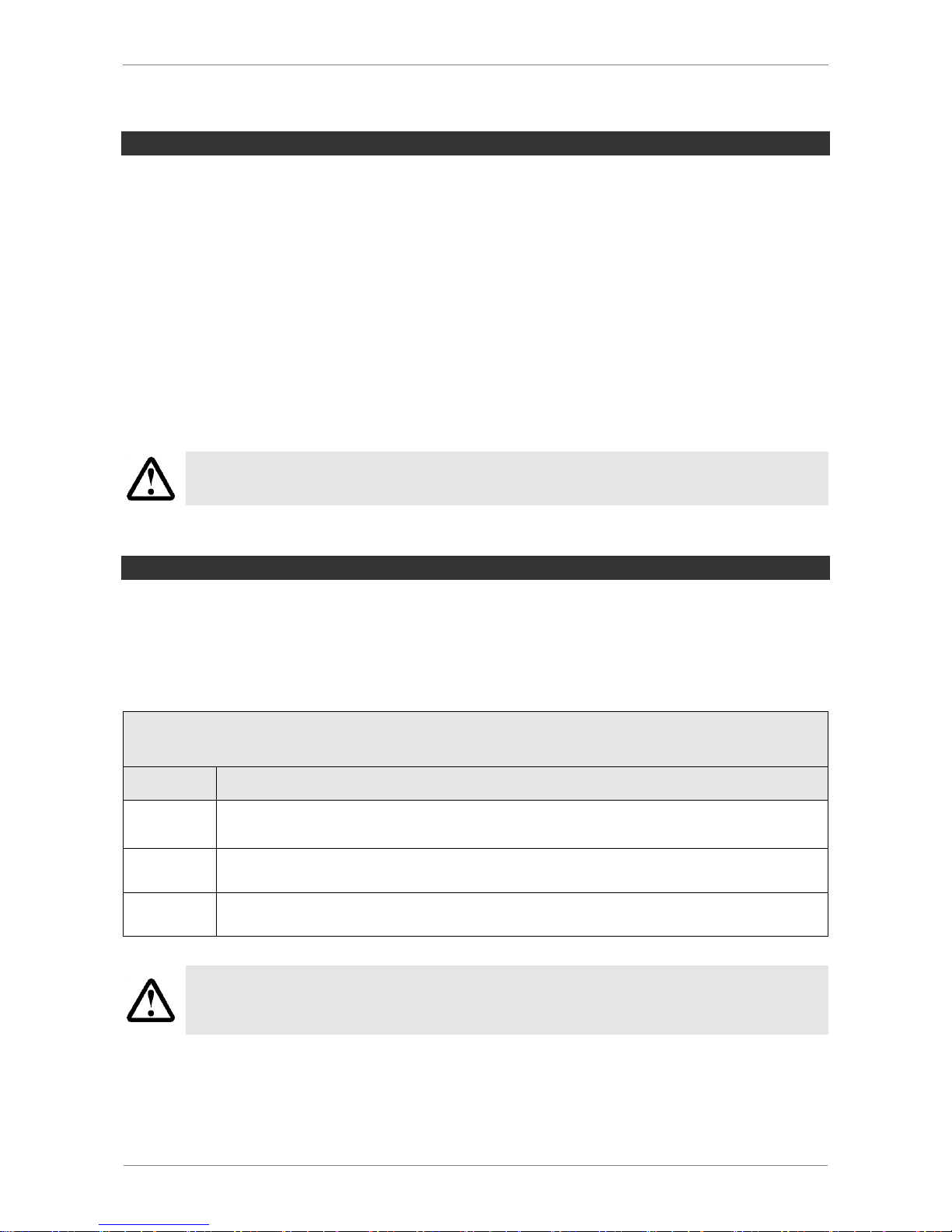
WRITE PROTECTION WITH DEVICE ACCESS LOCKS
In IO-Link mode, the “Device Access Locks” default parameter is available to prevent
changes to other parameter values using the user menu or IO-Link.
You can also prevent use of the data storage mechanism described in IO-Link Standard
V1.1.
Coding of the Device Access Locks
Bit
Meaning
0
Parameter write access locked
(Parameters cannot be changed via IO-Link)
1
Data storage locked
(Data storage mechanism is not triggered)
2
Local parametrization locked
(Parameters cannot be changed via the user menu)
Previous locking of the menu using the Device Access Locks parameter will be
retained in the SIO operating mode. It can only be removed using IO-Link, not in
the menu itself.
Page 24
SCHMALZ SCPSI - 2
3-24
RESET TO FACTORY SETTINGS
This function restores the ejector configurations of the initial setup and the settings of the
active production setup profile to the factory settings.
This function does not affect counter readings, the zero-point adjustment of the sensor or
the “Application Specific Tag” IO-Link parameter.
The function is carried out in the configuration menu under the [rES] menu item or via IOLink.
The factory settings of the ejector can be found in the appendix.
The function for restoring the factory settings does not affect the currently inactive production setup profiles.
Restoring the factory settings will change the switching points and the configuration of the signal output. This can change the status of the ejector system.
COUNTER
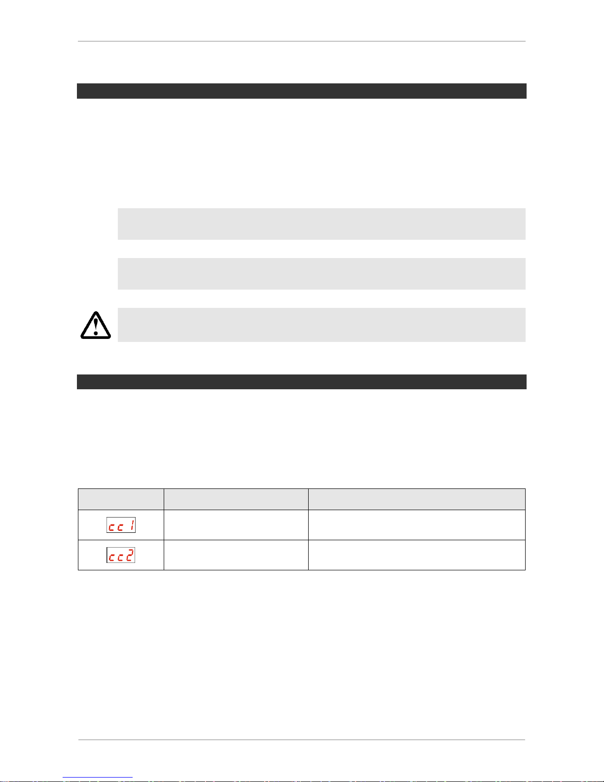
The ejector has two internal counters that cannot be deleted: [cc1] and [cc2].
Counter 1 increases with each valid pulse at the “Suction” signal input, meaning that it
counts all the suction cycles during the ejector’s service life. Counter 2 increases each ti-
me the “Suction” valve is switched on. As a result, the average switching frequency of the
air saving function can be determined using the difference between counters 1 and 2.
Symbol
Funktion
Beschreibung
Counter1
Counter for suction cycles
(suction signal input)
Counter2
Counter for the suction valve switching frequency
The counters can be read out using the system menu or IO-Link.
Page 25

SCHMALZ SCPSI - 2
3-25
VOLTAGE MONITORING
All ejector types have an internal voltage monitor. If the supply voltage falls below the
permitted threshold, the ejector has the E07 error status. This appears in the display, and
prevents menu operation and response to the signal inputs. The component check output
retains its normal functionality. The current supply voltage can still be viewed using the
key.
The pneumatic state of the ejector changes as follows:
NO EJECTOR TYPE
The ejector switches to „Suction“ mode
NC EJECTOR TYPE
The ejector switches to “Pneumatically OFF” mode
The control function is canceled if the voltage drops while suction is active.
In addition, an excessive supply voltage will be detected and a corresponding error message will be generated.
EVALUATING THE INLET PRESSURE
The supply pressure level in the system cannot be measured by the ejector itself. However, it is possible to send the current measured value of the inlet pressure from the system controller to the device via IO-Link.
In this case, the ejector evaluates the pressure value and activates a condition monitoring
warning if the value is not optimal. If the pressure is considerably too low or too high, an
error message is also generated.
A pressure value must also be transferred to enable an estimate of the volume of compressed air consumed in the suction cycle to be made in the area of energy monitoring.
Page 26
SCHMALZ SCPSI - 2
3-26
SETTING THE BLOW-OFF VOLUME FLOW
+
-
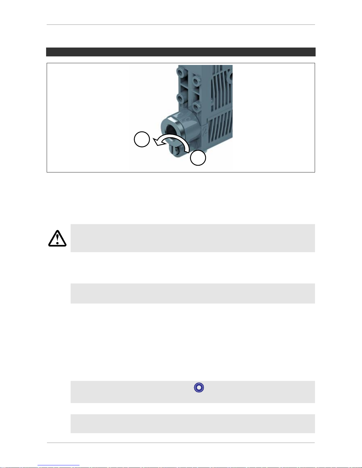
There is a valve screw below the vacuum connection (2). This valve screw can be used to
set the blow-off volume flow.
Turning the screw clockwise reduces the volume flow. Turning the screw counterclockwise
increases the volume flow.
The valve screw is equipped with a stop on both sides.
Do not turn the valve screw past the stops. A minimum volume flow of approx.
10% is always necessary for technical reasons.
The blow-off volume flow can be set between 10% and 100%.
PRODUCTION SETUP-PROFILES
Additional functions in IO-Link mode:
The functions described below are only available in IO-Link mode
The ejector can store up to four different production setup profiles (P-0 to P-3). All important data for workpiece handling is stored in these profiles. The profiles are selected
using the PDO byte 0 process data byte. This gives users a quick, convenient option for
adjusting the parameters to different workpiece properties.
The currently selected data set is displayed in the parameter data under “Production
Setup”. These are also the current parameters the ejector is working with, which can be
viewed using the menu.
If you select the basic menu by pressing , the parameter data set currently
being used will appear briefly in IO-Link mode.
In the default setting and in SIO mode, the P-0 production setup profile is selected.
Page 27
SCHMALZ SCPSI - 2
3-27
CONDITION MONITORING [CM]
Additional functions in IO-Link mode:
The functions described below are only available in IO-Link mode
MONITORING THE VALVE SWITCHING FREQUENCY
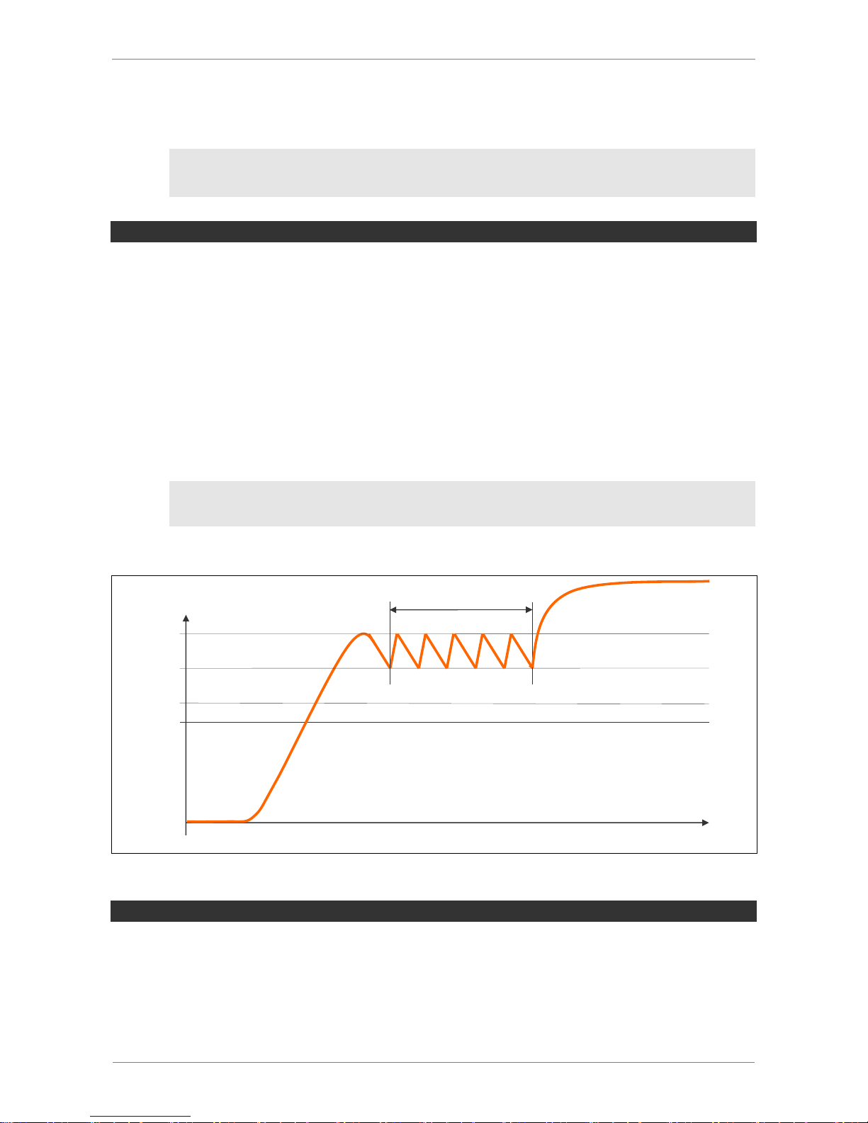
If the air-saving function is activated ([ctr = on] or [ctr = onS]) and the leakage rate in
the gripper system is high, the ejector is constantly switching between the “Venturi nozzle
active” and “Venturi nozzle inactive” states. The number of valve switching procedures
thus increases rapidly within a short time. In order to protect the ejector and increase its
service life, the ejector switches the air-saving function off automatically at a switching frequency of > 6/3 seconds and activates continuous suction (i.e., the ejector then remains in
the “Venturi nozzle active” state).
The basic monitoring of valve protection function is also active in the SIO mode.
In IO-Link mode, the appropriate condition monitoring warning is also set. In addition, thesystem status light switches to yellow.
The [dCS = ON] setting prevents continuous suction.
Vacuum
mbar
time
s
H1
H1-h1
H2
H2-h2
Vacuum On
> 6/3s
MONITORING THE CONTROL THRESHOLD
If the switching point H1 is never reached during the suction cycle, the “H1 not reached”
condition monitoring warning will be triggered and the system status light will switch to yellow.
This warning is available at the end of the current suction phase and remains active until
the next suction cycle.
Page 28
SCHMALZ SCPSI - 2
3-28
MONITORING THE EVACUATION TIME
If the measured evacuation time t1 (from H2 to H1) exceeds the specified value
[t-1], the “Evacuation time longer than t-1” condition monitoring warning will be triggered
and the system status light will switch to yellow.
The specified value for the max. permitted evacuation time can be set in the configuration
menu under [t-1] or using IO-Link. Setting the value to 0 (= off) deactivates monitoring.
The maximum permitted evacuation time setting is 9.99 s.
MONITORING LEAKAGE
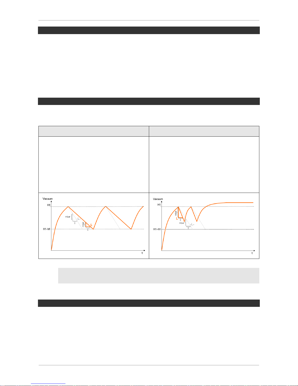
In control mode (ctr = onS), the drop in the vacuum level within a certain time is monitored (mbar/s). A distinction is made between two states.
Leckage L < [-L-]
Leckage L > [-L-]
If the leakage rate is less than the set value
[-L-] in mbar/s, the vacuum level continues
to fall until the switching point H1-h1 and
then the ejector resumes suction (normal
control mode).
The condition monitoring warning is not activated and there is no effect on the system
status light.
If the leakage rate is greater than the value
[-L-], the ejector immediately reacts to cor-
rect the vacuum level.
If the permitted leakage is exceeded twice,
the ejector switches to continuous suction.
The condition monitoring warning is acti-
vated and the system status light switches
to yellow.
The [dCS = ON] setting prevents continuous suction.
MONITORING THE DYNAMIC PRESSURE
If possible, a dynamic pressure measurement is taken at the start of every suction cycle.
The result of this measurement is compared to the threshold values set for H1 and H2.
If the dynamic pressure is greater than (H2 – h2) but less than H1, the corresponding condition monitoring warning will be set and the system status light will switch to yellow.
Page 29
SCHMALZ SCPSI - 2
3-29
EVALUATING THE LEAKAGE LEVEL
This function determines the average leakage during the last suction cycle, divides it into
subareas and makes it available as a parameter via IO-Link.
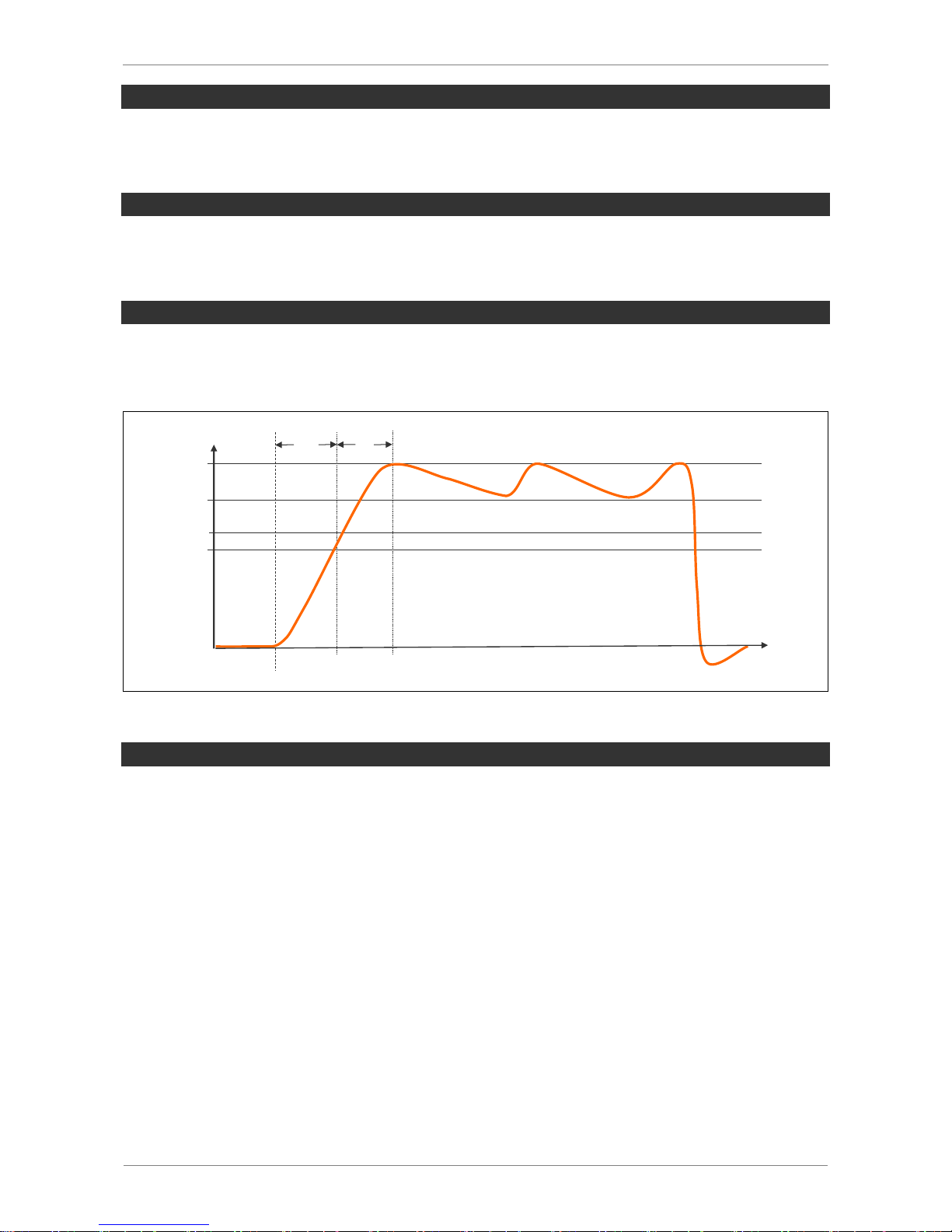
MEASUREMENT OF THE EVACUATION TIME t0
This measures the time (in ms) from the beginning of a suction cycle, started by the
command “Suction ON”, until the switching threshold H2 is reached.
MEASUREMENT OF THE EVACUATION TIME t1
This measures the time (in ms) from when the switching threshold H2 is reached until the
switching threshold H1 is reached.
Vacuum
mbar
H1
H1-h1
H2
H2-h2
Vacuum On
t0 t1
time
s
AUTOSET
The CM Autoset IO-Link function in the process output data allows the condition monitoring parameters for maximum permitted leakage (-L-) and evacuation time (t-1) to be set
automatically. The actual values from the last suction cycle are combined with additional
tolerance and stored.
Page 30

SCHMALZ SCPSI - 2
3-30
ENERGY MONITORING [EM]
Additional functions in IO-Link mode:
The functions described below are only available in IO-Link mode
The ejector offers functions for measuring and displaying the energy consumption to help
further optimize the energy efficiency of vacuum gripper systems.
The values are determined from comparison tables according to current process
parameters. Although the ejector is not a calibrated measuring devices, the values can be used as a reference and for relative measurements.
PERCENTUAL AIR CONSUMPTION MEASUREMENT
All ejectors calculate the percentual air consumption of the last suction cycle. This value
corresponds to the ratio of the active suction/blow-off times to the total duration of the suction cycle.
ABSOLUTE AIR CONSUMPTION MEASUREMENT
An externally recorded pressure value can supplied using the IO-Link process data. If this
value is available, not only a percentage-based air consumption measurement, but also an
absolute air consumption measurement can be performed.
The actual air consumption of a suction cycle is calculated by taking into account the system pressure and the nozzle size.
An absolute air consumption measurement can only be made using a pressure
value supplied externally via IO-Link.
ENERGY CONSUMPTION MEASUREMENT
The ejector determines the electrical energy consumed during a suction cycle, including
the energy it consumes itself and the energy consumed by the valve coils.
Page 31

SCHMALZ SCPSI - 2
3-31
PREDICTIVE MAINTENANCE [PM]
Additional functions in IO-Link mode:
The functions described below are only available in IO-Link mode
For early detection of wear and other impairments to the vacuum gripper system, the ejector features functions for detecting trends in the system’s quality and performance. Leakage and dynamic pressure are measured for this purpose.
MEASUREMENT OF THE LEAKAGE
This measures the leakage (drop in vacuum level per unit of time in mbar/s) after the control function has halted suction because the threshold value H1 was reached.
MEASUREMENT OF THE DYNAMIC PRESSURE
This measures the system vacuum achieved during unobstructed intake. The duration of
the measurement is approx. 1 s. To perform a valid dynamic pressure value evaluation, it
is therefore necessary to allow the ejector to suck in air unobstructed for at least 1 s after
suction begins, i.e., the suction cell must not yet be covered by a component.
Measured values that are above the threshold value H1 are output as 0 mbar to indicate
that a valid dynamic pressure measurement could not be performed.
Measured values that are greater than the threshold value (H2 – h2) but less than the
threshold value H1 trigger a condition monitoring event.
QUALITY ASSESSMENT
To evaluate the entire gripper system, the ejector calculates a quality assessment value
based on the measured leakage in the system.
The greater the leakage in the system, the poorer the quality of the gripper system. Accordingly, low leakage leads to a high quality assessment value.
PERFORMANCE CALCULATION
Similar to the quality assessment, the performance calculation is used to assess the system state. The measured dynamic pressure can be used as a measure of the performance
of the gripper system.
Optimally designed gripper systems lead to low dynamic pressures and thus high performance; poorly designed systems result in low performance values.
Dynamic pressure measurements that are greater than the threshold value (H2– h2) always result in a performance rating of 0%. A performance rating of 0% is also issued for a
dynamic pressure of 0 mbar (which serves as an indication that the measurement was not
valid).
Page 32

SCHMALZ SCPSI - 2
3-32
DIAGNOSTIC BUFFER
The condition monitoring warnings described above and the general error messages from
the device are saved in a diagnostic buffer.
The content of this memory is made up of the last 38 events, starting with the most recent,
and can be read out via an IO-Link parameter. For each event, the current reading of the
suction cycle counter cc1 is also saved to allow subsequent temporal assignment of the
events to other processes in the system. See the associated IO-Link Data Dictionary for
the actual data display of the diagnostic buffer.
The recording of these events is also active in SIO mode and the contents of the memory
is retained after a power failure. The memory is deleted manually using the IO-Link system
command “Clear diagnostic buffer” or also by restoring the factory settings on the device.
EPC DATA BUFFER
The ejector provides a ten-stage data buffer to enable long-term monitoring and trend analysis of the most important key figures in a handling process. The current measurement
values for the evacuation time t1, the leakage rate and the dynamic pressure (vacuum
during unobstructed intake) determined during the suction cycle can be saved in this buffer.
The values are saved automatically, always together with the execution of the Autoset
function in condition monitoring described above. For each data record, the current reading of the suction cycle counter cc1 is also saved to allow subsequent temporal assignment to other processes in the system. The contents of the EPC data buffer can be read
out via an IO-Link parameter. See the associated IO-Link Data Dictionary for the actual
data display of this buffer. The contents of the memory remains intact after a power failure.
Page 33
SCHMALZ SCPSI - 2
4-33
4 OPERATING AND MENU CONCEPTS
The unit is operated via four buttons on the foil keypad. Settings are made using software
menus. The operating structure is divided into settings in the main menu and in the configuration menu. Configuring the ejector in the main menu is sufficient for standard applications. An extended configuration menu is available for applications with special requirements.
If settings are changed, this can cause undefined changes to the system status
for a shot period of time (approx. 50 ms) in certain situations.
VACUUM DISPLAY
The ejector is in display mode when the menus are not being accessed. The current vacuum or the current system pressure is displayed.
If there is overpressure in the suction circuit, this is indicated by the ejector with the display
“-FF”. This normally always happens in blow-off mode.
An excessive vacuum value (outside of the measurement range) is indicated by the display“FFF”.
INDIVIDUAL FUNCTIONS
In display mode, a specific function is assigned to each key.
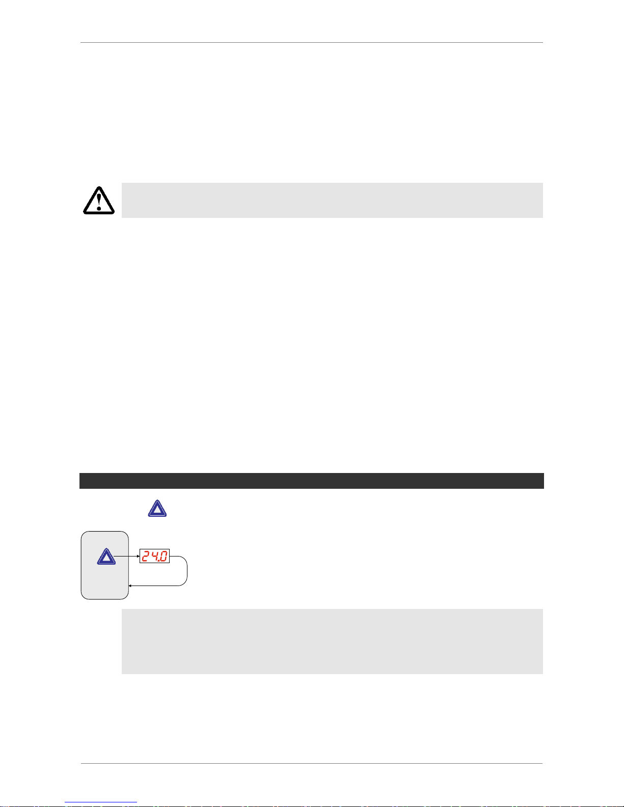
SUPPLY VOLTAGE
Pressing the key displays the supply voltage currently applied to the ejector.
Supply
voltage
3 sec.
The display returns to the vacuum display after 3 s.
The ejector is not a calibrated measuring device, but the voltage displayed can
still be used as a reference value and for comparative measurements.
Page 34
SCHMALZ SCPSI - 2
4-34
OPERATING MODE DISPLAY
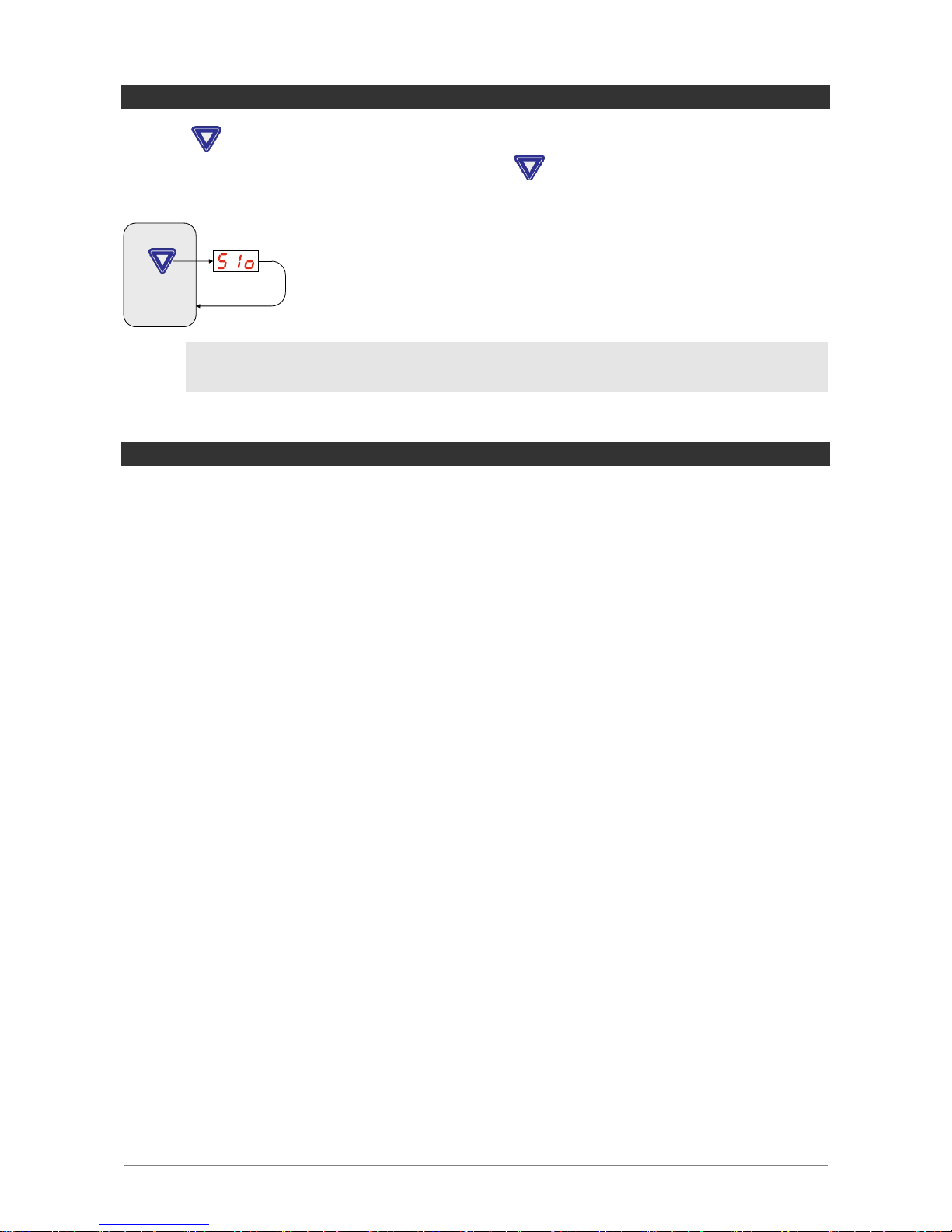
Pressing displays the current operating mode, either standard I/O (SIO) mode or IOLink mode. In IO-Link mode, you can also press again to view the IO-Link Standard
(1.0, 1.1) currently in use.
3 sec
Operating
mode
The display returns to the vacuum display after 3 s.
ERROR DISPLAY
If an error occurs, it appears on the display in the form of an error code (E number). The
ejector’s response to an error depends on the type of error.
You can find a list of possible errors and the corresponding codes in Sec. 7.
Any operation being performed in the menu will be interrupted if an error occurs. The error
code can also be opened as a parameter using IO-Link.
Page 35
SCHMALZ SCPSI - 2
4-35
MAIN MENU
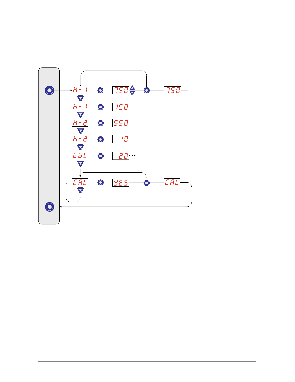
All settings for standard ejector applications can be read and changed using the main
menu.
> 2 sec.
> 2 sec.
> 2 sec.
Value flashes
to confirm
Continue
to h-1
Setting the
value
flashing
flashing
Switching point for the
air saving function
Hysteresis
of air-saving function
Switching point for the
component check
Hysteresis of the
component check
Blow off time, only
activated for E-t or l-t
Calibration of the
vacuum sensor
Functions shown in dotted lines are only available in certain functional scenarios.
Page 36
SCHMALZ SCPSI - 2
4-36
SETTING THE PARAMETERS IN THE MAIN MENU
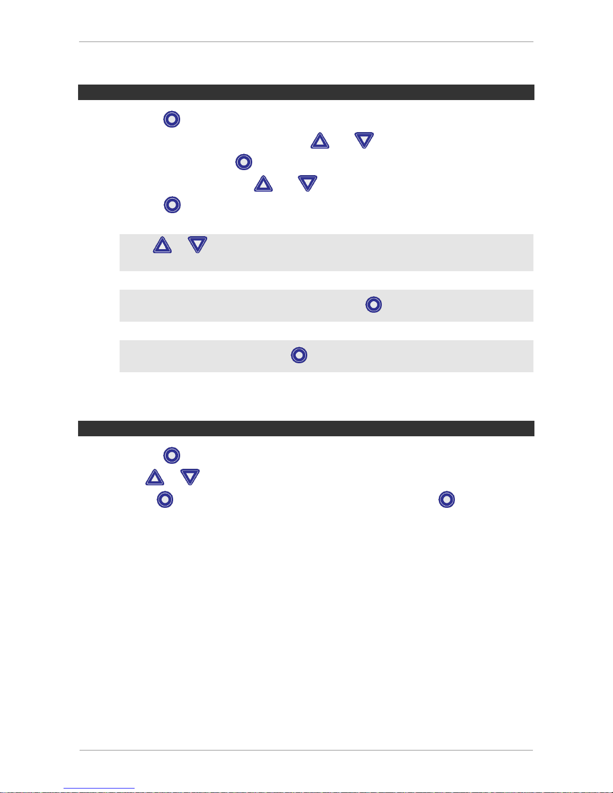
Briefly press the button to set the parameters in the main menu.
Select the desired parameter using the and buttons.
Confirm by pressing the button.
Change the value using the and buttons.
Press the button > 2 s to save the changed value.
If the or button is pressed for approx. 3 seconds, the value to be changed begins to quickly scroll through the available options.
If you exit the changed value by briefly pressing , the value will not be aplied.
To exit the basic menu press the key > 2 s.
ZERO-POINT ADJUSTMENT (CALIBRATION)
Briefly press the button to adjust the zero point of the integrated sensors.
Press or until [CAL] appears in the display.
Use the key to confirm, and once [YES] appears, press the key > 2 s. The
vacuum sensor is only calibrated
Page 37
SCHMALZ SCPSI - 2
4-37
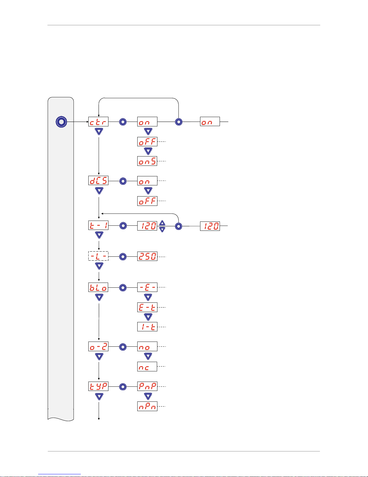
CONFIGURATION MENU
An extended configuration menu is available for applications with special requirements.
The operating structure is as follows:
back to ctr
flashing
> 2 sec.
> 2 sec.
> 3 sec.
back to t-1
flashing
Air saving function
Control shutoff
deactivated
No continuous suction
Max. permitted
evacuation time
Evaluation only in
IO-Link
Max. permitted
leakage Only activated with onS
Blw-off function
External time control,
internal time control
Output function
Signal type of the inputs and outputs
Page 38
SCHMALZ SCPSI - 2
4-38
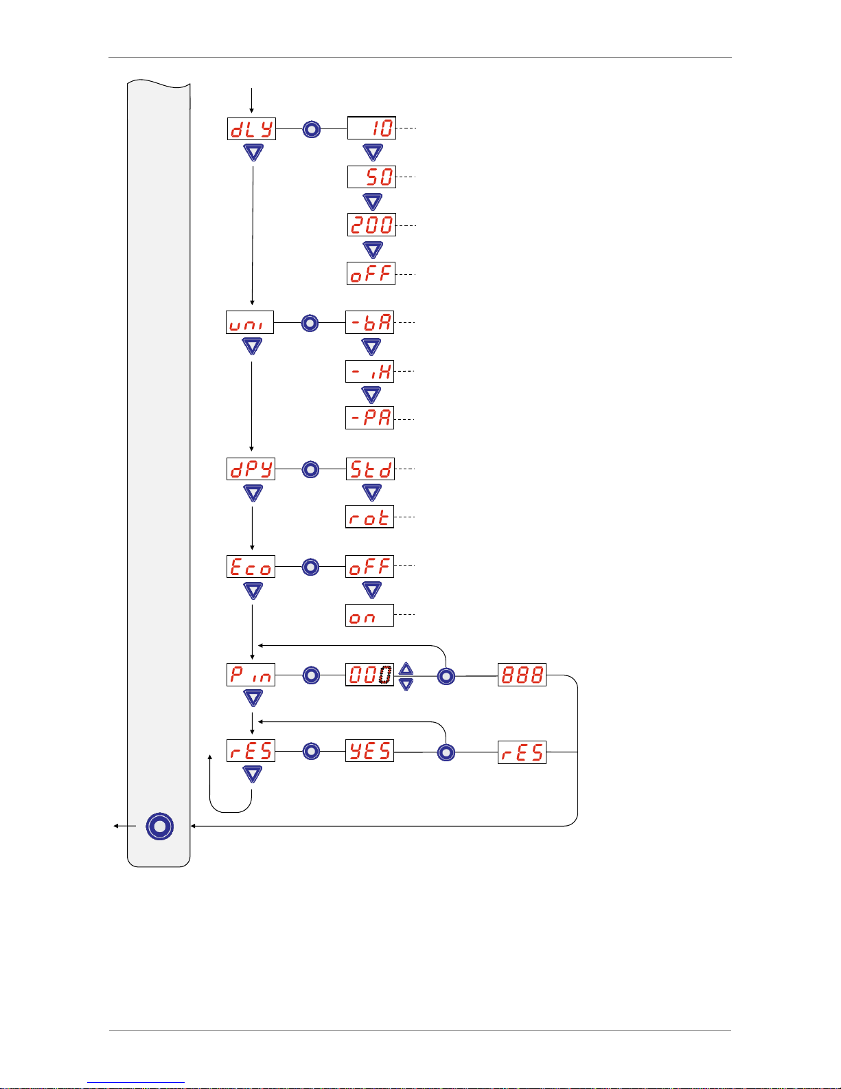
> 2 sec.
> 2 sec.
> 2 sec.
1st digit
flashes
flashing
flashing
Switch-Off Delay of the
signal H2
Vacuum unit displayed
180° display rotation
Display in ECO mode
Locking the menu
using a PIN
Press menu for 2 sec.
=> Save
Briefly press menu
=> Cancel
Restoring the
factory settings
Page 39

SCHMALZ SCPSI - 2
4-39
SETTING THE PARAMETERS IN THE CONFIGURATION MENU
Press the button for longer than 3 s to set the parameters in the configuration menu.
During activation, [-C-] will appear.
Select the desired parameter using the and buttons.
Confirm by pressing the button.
Change the value using the or button.
Press the button > 2 s to save the changed value.
If the or button is pressed for approx. 3 seconds, the value to be changed begins to quickly scroll through the available options.
If you exit the changed value by briefly pressing , the value will not be aplied.
To exit the configuration menu press the key > 2 s.
ENTERING THE PIN
Press the for longer than 3 s to enter the PIN.
Use the and buttons to select the [Pin] menu item.
Confirm by pressing the button.
Enter the first digit of the PIN code using the and buttons.
Confirm by pressing the button.
Enter the remaining digits in the same way.
Press the button for longer than 2 seconds to save the PIN.
[Loc] flashes in the display and the configuration menu is exited.
EXECUTING THE “RESET TO FACTORY SETTINGS” FUNCTION
Press the button for longer than 3 seconds to execute this function.
Use the and buttons to select the [rES] menu item.
Use the key to confirm, and once [YES] appears, press the key > 2 s. The
ejector is now restored to the factory settings.
After confirmation, the display flashes for three seconds and then automatically returns to
display mode.
Page 40
SCHMALZ SCPSI - 2
4-40
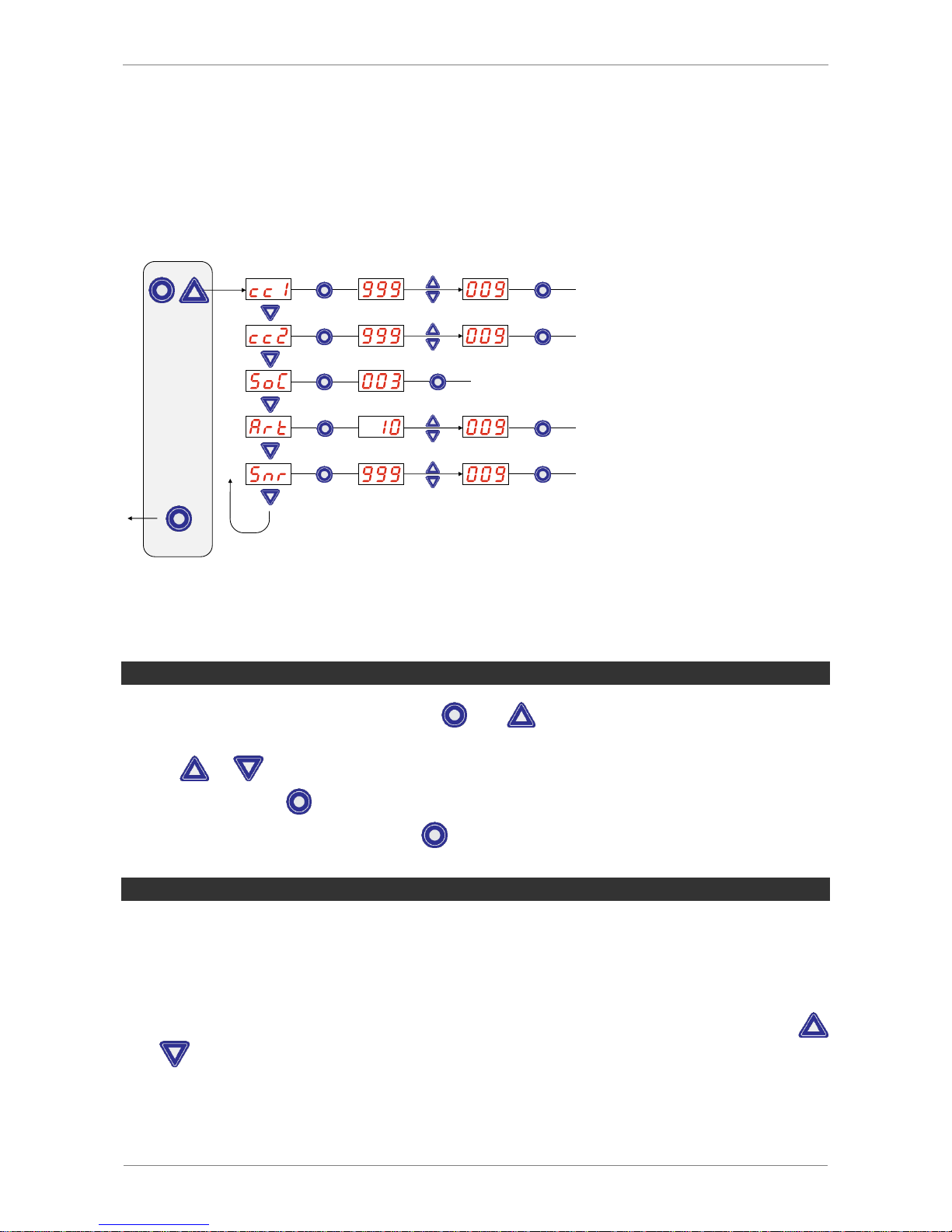
SYSTEM MENU
A special menu is available for reading out system data such as counters, software version, part numbers and serial numbers. The operating structure is as follows:
back to cc1
X * 10
6
> 3 sec.
> 2 sec.
back to cc2
back to SoC
back to Art
back to Snr
X * 10
0
X * 10
6
X * 10
0
X * 10
6
X * 10
0
Counter 1
Counter 2
Software version
Part number
Serial number
VIEWING DATA IN THE SYSTEM MENU
To view data in the system menu, press and at the same time for more than 3 seconds. During activation, [-S-] will appear.
Use or to select the value to be displayed
Confirm using the key. The value is displayed
To exit the system menu, press the key > 2 s
VIEWING THE COUNTERS
This menu item displays the [cc1] (suction cycles) and [cc2] (number of valve switches)
counters.
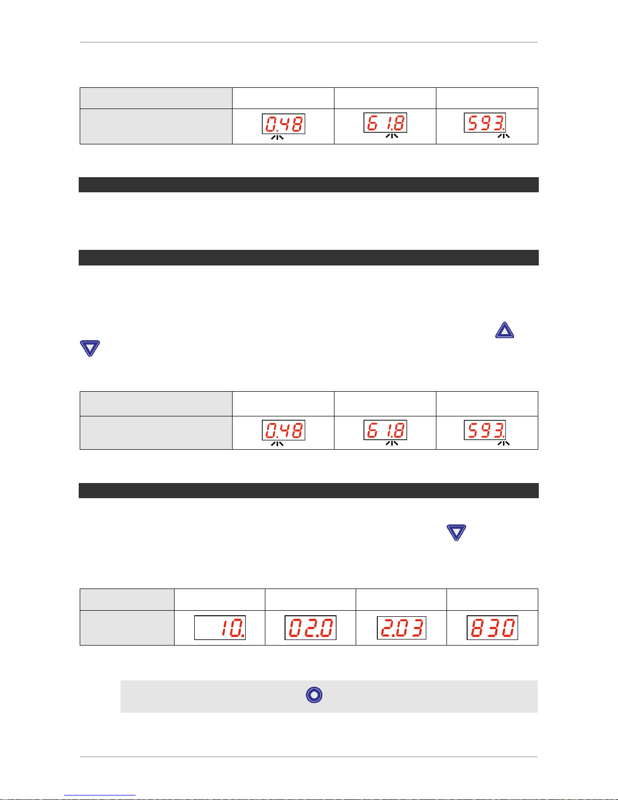
The last three decimal places of the total counter value are displayed. The decimal point at
the far right flashes. This corresponds to the three-digit block with the lowest significance.
The remaining decimal places of the total counter value can be displayed using the
and buttons. The decimal points indicate which three-digit block of the total counter
value is shown in the display.
Page 41
SCHMALZ SCPSI - 2
4-41
The total counter value consists of all the three-digit blocks together:
Displayed places
106
103
100
Block of digits
The current total counter value in this example is 48 618 593.
SOFTWARE VERSION
The software version indicates the software currently running on the internal controller.
SERIAL NUMBER
The serial number indicates the period in which the ejector was manufactured.
The last three decimal places of the serial number are displayed. The decimal point at the
far right flashes. This corresponds to the three-digit block with the lowest significance.
The remaining decimal places of the serial number can be displayed using the and
buttons. The decimal points indicate which three-digit block of the serial number is
shown in the display.
The serial number consists of all the three-digit blocks together:
Displayed places
106
103
100
Block of digits
The current serial number in this example is 48 618 593.
ARTICLE NUMBER
The part number both appears on the label on the ejector, and is stored electronically.
The first two places of the article number are shown initially. Press the button to dis-
play the remaining places of the article number. The decimal points displayed are part of
the article number. The article number consists of 11 places in total.
The part number consists of 4 digit blocks with 11 numbers.
1 2 3
4
Block of digits
The article number in this example is 10.02.02.003830.
To exit the system menu, press the key > 2s.
Page 42

SCHMALZ SCPSI - 2
5-42
5 OPERATING MODE
All ejectors of the SCPSi series have two operating modes. Users can choose between
direct connection to inputs and outputs (serial I/O = SIO mode) or connection through the
communication line (IO-Link).
By default, the ejector always runs in SIO mode, but it can be switched in and out of IOLink mode by an IO-Link master at any time.
SIO OPERATING MODE
OVERVIEW
When the ejector is operated in SIO mode, all signal inputs and outputs are connected to a
controller either directly or via intelligent connection boxes.
In addition to the power supply connection, this mode requires two signal inputs and one
signal output, via which the ejector communicates with the controller.
This means that the ejector’s basic suction and blow-off functions, as well as the “Component check” feedback function, can be used.
Ejector inputs
Ejector output
Suction ON/OFF
Blow-off ON/OFF
Feedback H2 (component check)
The “Blow-off” signal does not have to be used if the ejector is operated with internal time
control in blow-off mode. This allows operation on a single port in a configurable terminal
box (using 1xDO and 1xDI).
The parameters are set and the internal counters are read exclusively via the operating
and display elements.
Neither the condition monitoring (CM) events, nor the energy monitoring (EM) and predictive maintenance (PM) functions are available in SIO mode.
Page 43
SCHMALZ SCPSI - 2
5-43
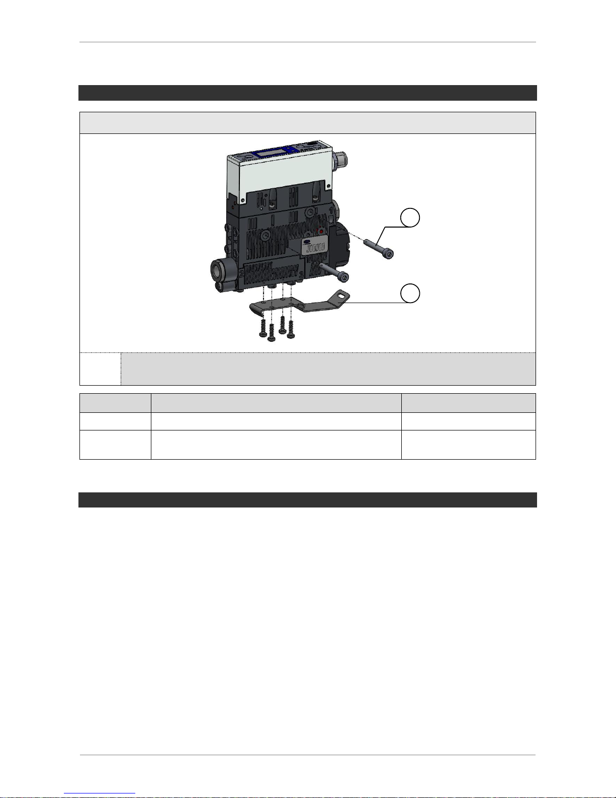
MOUNTING
SCPSi-2 …
1
2
We recommend using washers when mounting the securing screws.
Position
Description
Max. tightening torque
1
M4 securing screw
2 Nm
2
Top-hat rail clamp for TS35 top-hat rail, incl. plastic
tapping screws (optional)
0,5 Nm
PNEUMATIC CONNECTION
Use only well-maintained compressed air (air or neutral gas according to EN 983, fil-
tered to 5 µm, oiled or unoiled).
High-quality compressed air is important to ensure a long service life for the ejector.
Dirt particles or foreign bodies in the ejector connections, hoses or pipelines can lead to
partial or complete ejector malfunction.
Hoses and pipelines should be laid such that distances are minimized.
If the internal diameter on the compressed air side is too small, insufficient compressed
air will be supplied. This prevents the ejector from performing as specified in the performance data.
Excessive flow resistance occurs if the internal diameter on the vacuum side is too
small. This leads to both a reduction in suction capacity and increased evacuation
times. Blow-off times are also lengthened.
Hose lines must be laid without bends or crimps.
Only use hoses or pipes with the internal diameters recommended for the ejector. If this
is not possible, use the next largest internal diameter.
Page 44
SCHMALZ SCPSI - 2
5-44
RECOMMENDED LINE CROSS-SECTIONS (INTERNAL DIAMETERS)
SCPSi
performance class
Line cross-section (internal diameter) [mm]1)
Compressed air side
Vacuum side
07
2
4
09
4
4
14
4
6
1)
Based on a maximum hose length of 2 m. For longer hoses, the cross-section should be correspondingly larger.
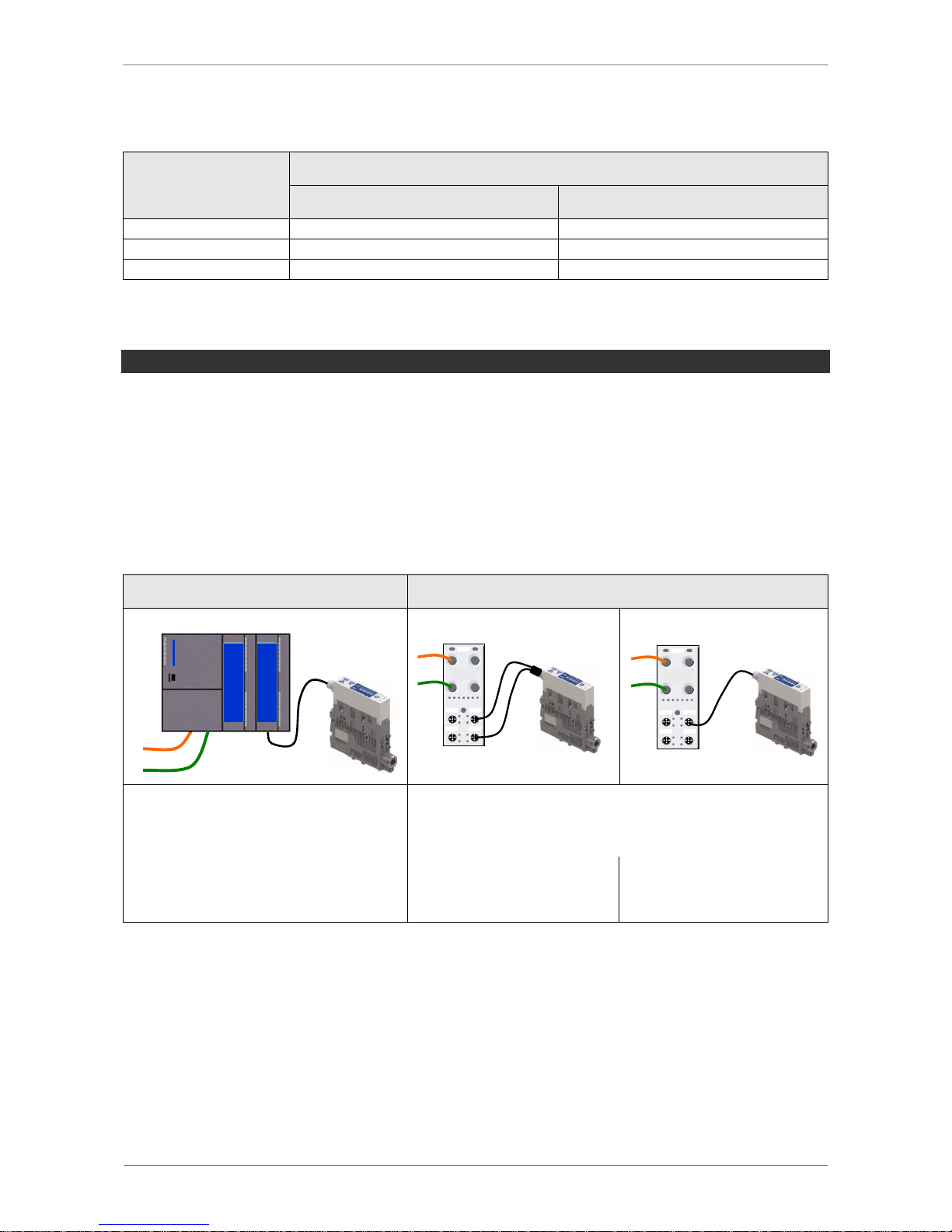
ELECTRICAL CONNECTION
The electrical connection of the ejector consists of an 5-pin M12 connector.
The plug connector may not be connected or disconnected while voltage is applied.
The ejector may only be operated using power supply units with protected extra-low
voltage (PELV). The system must incorporate safe electrical cut-off of the power supply
in compliance with EN60204.
The lines for the power supply, the signal inputs and the signal output can have a ma-
ximum length of 30 meters.
Direct connection
Connection via I/O box
Schmalz connection lines may be
used to connect the ejector directly
to the controller.
Schmalz connection distributors and Schmalz
connection lines may be used to connect the ejector
to IO boxes.
Art. no. 21.04.05.00080 (5-pin)
Art.-No.
10.02.02.03490
M12-5 to 2xM12, 1m
Art.-No.
21.04.05.00158
M12-5 to M12-5, 1m
BUS
US / UA
BUS
I/O
US / UA
BUS
I/O
Page 45
SCHMALZ SCPSI - 2
5-45
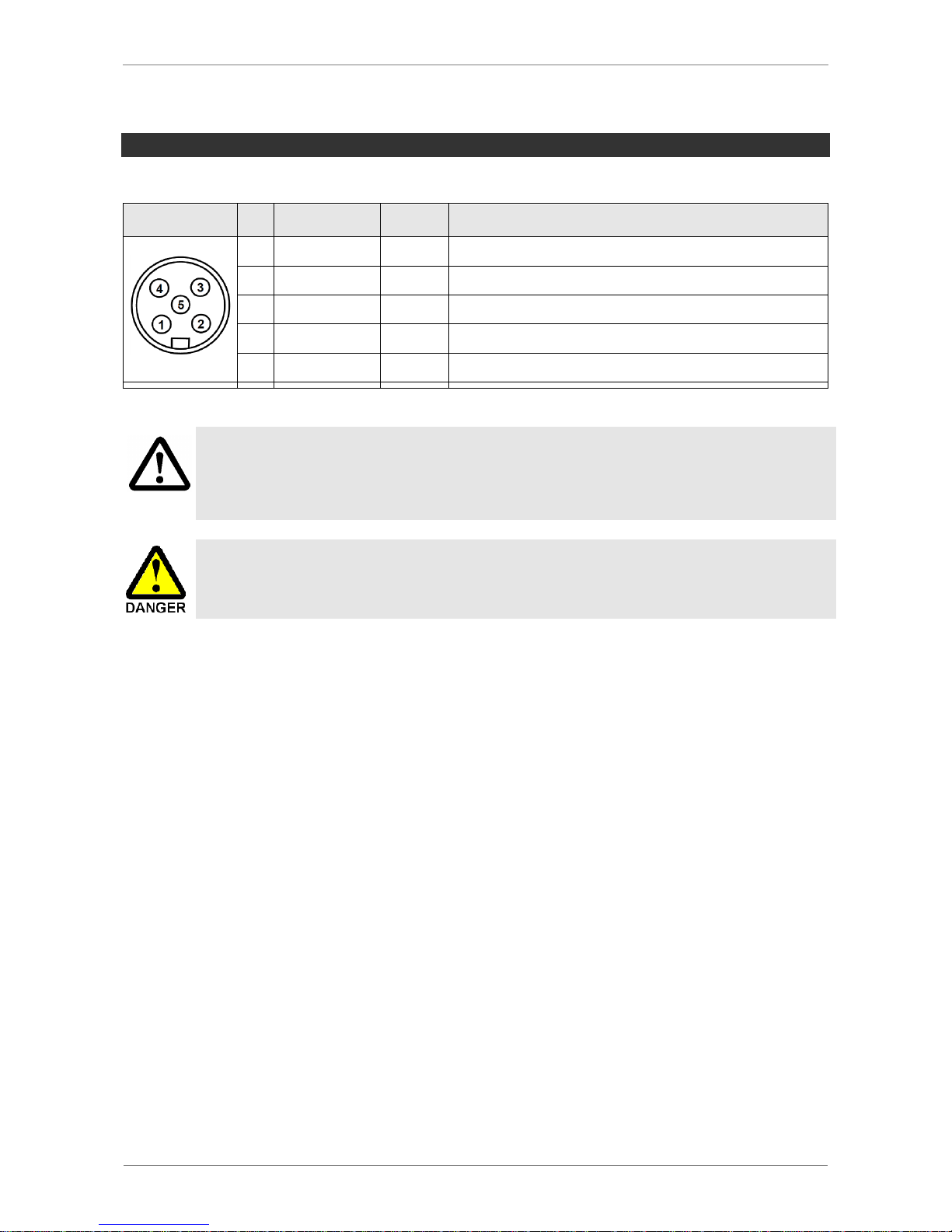
PIN ASSIGNMENT OF THE CONNECTION PLUG
M12 5-PIN CONNECTOR
Plug
Pin
Lead color
1)
Symbol
Function
1
Brown
U
S/A
Supply voltage for sensors/actuators
2
White
IN1
“Suction” signal input
3
Blue
Gnd
S/A
Ground for sensors/actuators
4
Black
OUT
“Component check” signal output (H2/h2)
5
Gray
IN2
“Blow-off” signal input
1)
When Schmalz connection line is used, art. no. 21.04.05.00080
Vorsicht
Vorsicht
The system may only be operated using power supply units with protected extra-low voltage (PELV) and safe electrical cut-off of the operating voltage, in accordance with EN60204.
Do not forcibly connect or disconnect plug connectors.
The signal output may change if the supply voltage is switched on or the M12
plug connector is plugged in. Depending on the function of the machine/system,
this can result in serious personal injury or damage to the equipment.
Page 46
SCHMALZ SCPSI - 2
5-46
PROJEKTIEREN
For operation of the ejector, all process signals must be wired in parallel. This means that
three lines for the process signals are required for each ejector.
PROCESS DATA INPUT
Signal
Symbol
Parameter
0
OUT 1
Switching point H2 (component check)
PROCESS DATA OUTPUT
Signal
Symbol
Parameter
0
IN 1
Suction ON/OFF
1
IN 2
Blow-off ON/OFF
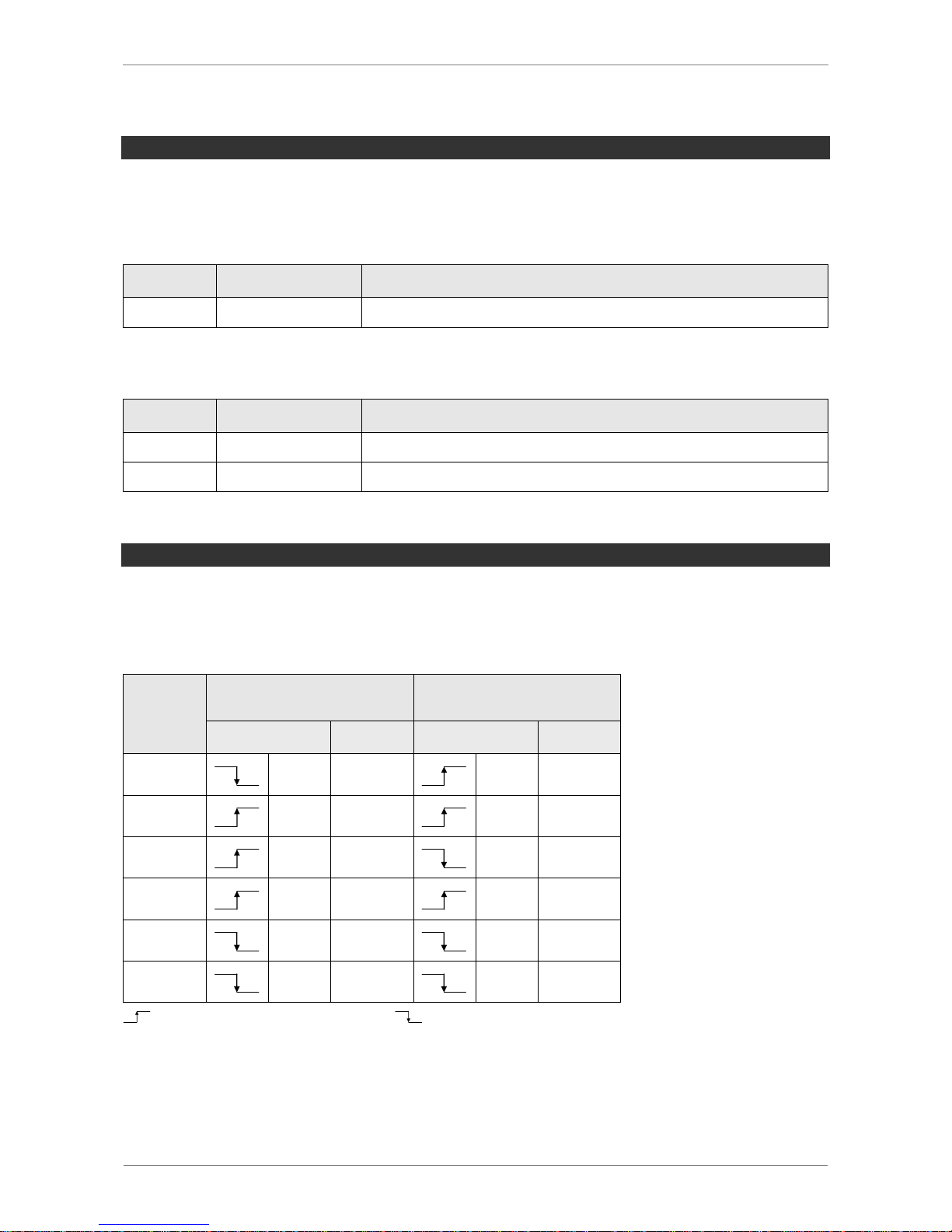
START OF OPERATIONS
A typical handling cycle is divided into three steps: pick-up, blow-off and the idle state.
During the pick-up step, output 2 is monitored to determine whether a sufficient vacuum
has been established.
Step
SCPS – xx – NO – xx
SCPS – xx – NC – xx
Signal
State
Signal
State
1
IN1
Saugen
EIN
IN1
Saugen
EIN
2
OUT2
Vakuum
> H2
OUT2
Vakuum
> H2
3
IN1
Saugen
AUS
IN1
Saugen
AUS
4
IN2
Abblasen
EIN
IN2
Abblasen
EIN
5
IN2
Abblasen
AUS
IN2
Abblasen
AUS
6
OUT2
Vakuum
< (H2-h2)
OUT2
Vakuum
< (H2-h2)
Signal status switches from inactive to active |
Signal status switches from active to inactive
Page 47
SCHMALZ SCPSI - 2
5-47
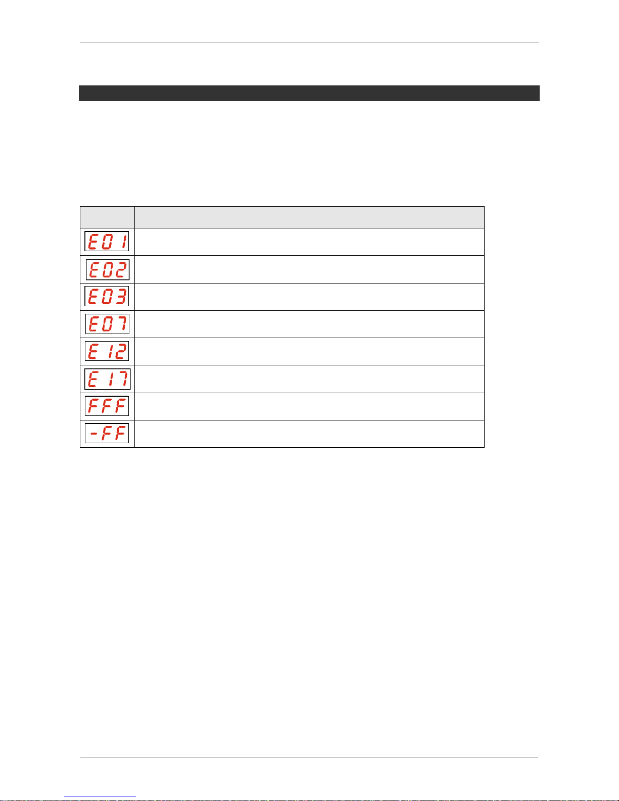
WARNINGS AND ERRORS
WARNINGS
Warnings are only available via IO-Link.
ERROR
Error messages from the ejector are shown in the display.
Symbol
Error code
Electronics error - EEPROM
Electronics error – internal communication
Zero point of vacuum/pressure sensor adjusted outside of 3% FS
Supply voltage is too low
Short-circuit at output 2
Supply voltage is too high
Current vacuum or pressure exceeds the measurement range
Excess pressure in the vacuum circuit
Page 48

SCHMALZ SCPSI - 2
5-48
IO-LINK MODE
OVERVIEW
When operating the ejector in IO-Link mode (digital communication), only the power supply
and the communication line must be connected to a controller directly or via intelligent
connection boxes.
The communication line for IO-Link (C/Q line) must always be connected to an IO-Link
master port (point-to-point connection). It is not possible to connect multiple C/Q lines to
only one IO-Link master port.
When the ejector is connected via IO-Link, a number of additional functions are available
beyond the basic functions of the ejector (suction, blow-off, feedback signals, etc.). This
includes but is not limited to:
Current vacuum and pressure value
Selection of four production profiles
Errors and warnings
Ejector system status display
Access to all parameters
Counters
Condition monitoring
Energy monitoring
Predictive Maintenance
In this mode, all adjustable parameters can be read, changed and written to the ejector
directly using the higher-level controller.
The condition and energy monitoring results can be evaluated to produce trend analyses
and to provide direct information on the current handling cycle.
The ejector supports the IO-Link revision 1.1 with four bytes of input data and two bytes of
output data.
It is also compatible with IO-Link masters that use the 1.0 revision. In this case, one byte
of input data and one byte of output data are supported.
The exchange of process data between the IO-Link master and the ejector is cyclical. Parameter data (acyclical data) is exchanged by the user program in the controller using
communication modules.
Page 49
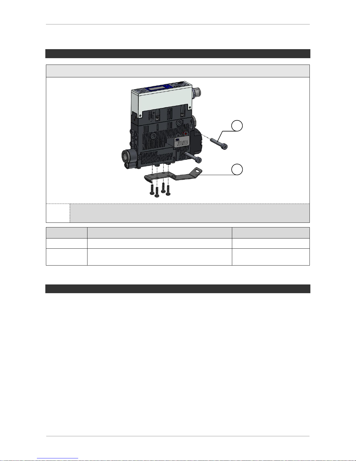
SCHMALZ SCPSI - 2
5-49
MOUNTING
SCPSi-2 …
1
2
We recommend using washers when mounting the securing screws.
Position
Description
Max. tightening torque
1
M4 securing screw
2 Nm
2
Top-hat rail clamp for TS35 top-hat rail, incl. plastic
tapping screws (optional)
0,5 Nm
PNEUMATIC CONNECTION
Use only well-maintained compressed air (air or neutral gas according to EN 983, fil-
tered to 5 µm, oiled or unoiled).
High-quality compressed air is important to ensure a long service life for the ejector.
Dirt particles or foreign bodies in the ejector connections, hoses or pipelines can lead to
partial or complete ejector malfunction.
Hoses and pipelines should be laid such that distances are minimized.
If the internal diameter on the compressed air side is too small, insufficient compressed
air will be supplied. This prevents the ejector from performing as specified in the performance data.
Excessive flow resistance occurs if the internal diameter on the vacuum side is too
small. This leads to both a reduction in suction capacity and increased evacuation
times. Blow-off times are also lengthened.
Hose lines must be laid without bends or crimps.
Only use hoses or pipes with the internal diameters recommended for the ejector. If this
is not possible, use the next largest internal diameter.
Page 50
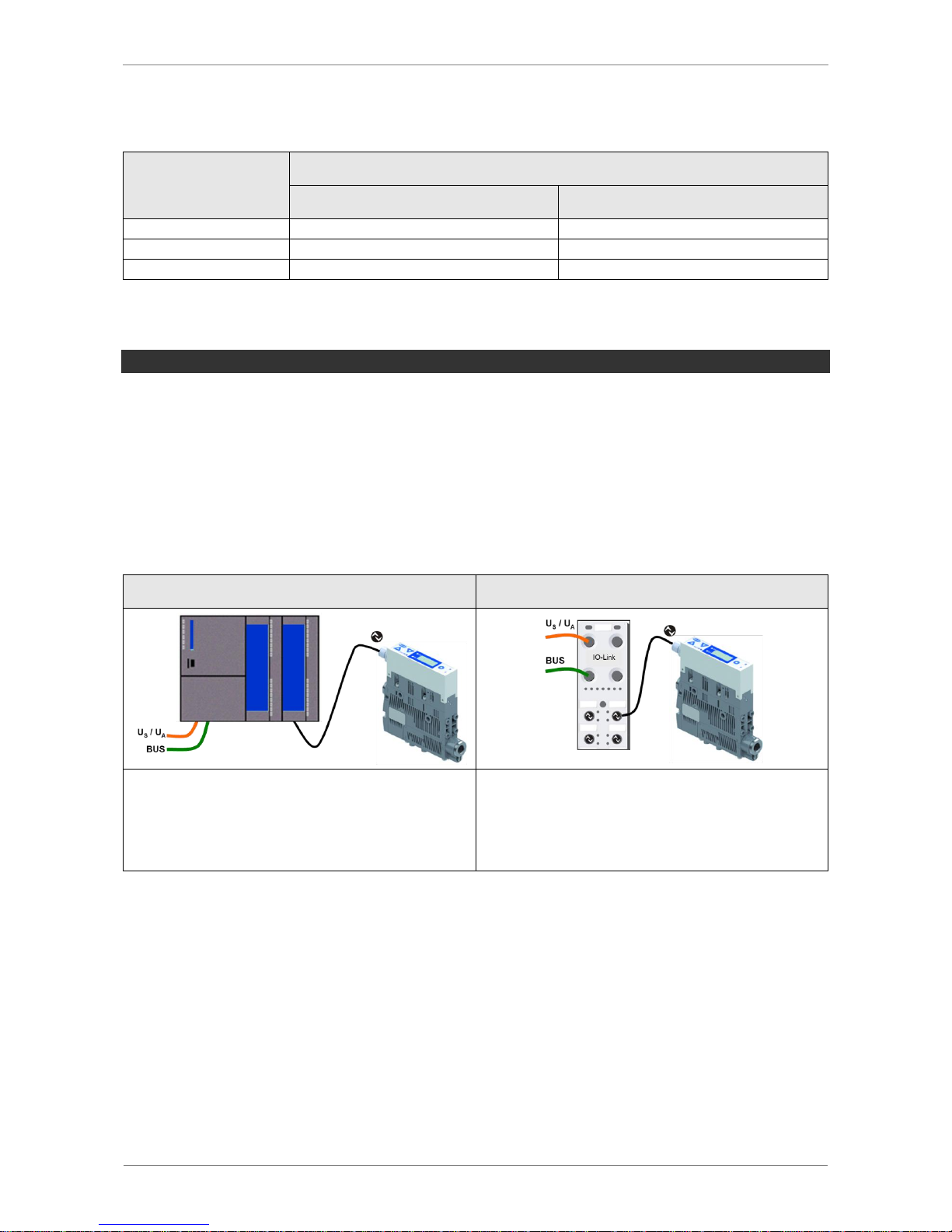
SCHMALZ SCPSI - 2
5-50
RECOMMENDED LINE CROSS-SECTIONS (INTERNAL DIAMETERS)
SCPSi
performance class
Line cross-section (internal diameter) [mm]1)
Compressed air side
Vacuum side
07
2
4
09
4
4
14
4
6
1)
Based on a maximum hose length of 2 m. For longer hoses, the cross-section should be correspondingly larger.
ELECTRICAL CONNECTION
The electrical connection of the ejector consists of an 5-pin M12 connector.
The plug connector may not be connected or disconnected while voltage is applied.
The ejector may only be operated using power supply units with protected extra-low
voltage (PELV). The system must incorporate safe electrical cut-off of the power supply
in compliance with EN60204.
The lines for the power supply, the signal inputs and the signal output can have a ma-
ximum length of 20 meters.
Direct connection
Connection via I/O box
A Schmalz connection line may be used to
connect the ejector directly to the controller.
Art.-No. 21.04.05.00080
A Schmalz connection line may be used to
connect the ejector to IO-Link master boxes.
Art.-No. 21.04.05.00158
Page 51
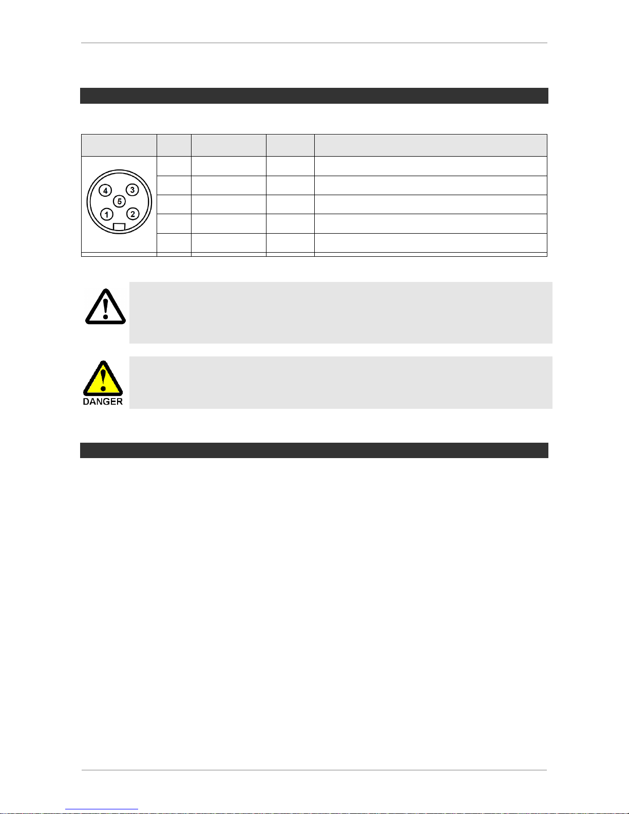
SCHMALZ SCPSI - 2
5-51
PIN ASSIGNMENT OF THE CONNECTION PLUG
M12 5-PIN CONNECTOR
Plug
Pin
Lead color
1)
Symbol
Function
1
Brown
U
S/A
Power supply Sensor / Actuator
2
White
-
-
3
Blue
Gnd
S/A
Sensor / Actuator ground
4
Black
C/Q
IO-Link communication line
5
Gray
-
-
1)
When Schmalz connection line is used, art. no. 21.04.05.00080
Vorsicht
Vorsicht
The system may only be operated using power supply units with protected extra-low voltage (PELV) and safe electrical cut-off of the operating voltage, in accordance with EN60204.
Do not forcibly connect or disconnect plug connectors.
The signal output may change if the supply voltage is switched on or the M12
plug connector is plugged in. Depending on the function of the machine/system,
this can result in serious personal injury or damage to the equipment.
PROJECT PLANNING
To operate the ejector in IO-Link mode, you only need to connect an IO-Link connection
line (C/Q) in addition to the power supply. Each ejector therefore only requires one line for
all process and parameter data.
The ports on an IO-Link master typically have to be switched to IO-Link mode first. This is
done using the configuration tool supplied by the manufacturer of the master or controller.
The port can be configured generically for IO-Link by entering the correct process data
length for the IO-Link device and possibly also storing standard settings for the required
manufacturer ID and device ID in the master.
Alternatively, the electronic device description file, or IODD, can be used. To do this, an
IO-Link configuration tool from the master manufacturer must be available into which the
IODD is imported. This kind of tool displays all process and parameter data for the device
in a meaningful format and enables convenient offline parameterization or also observation
during operation.
Page 52
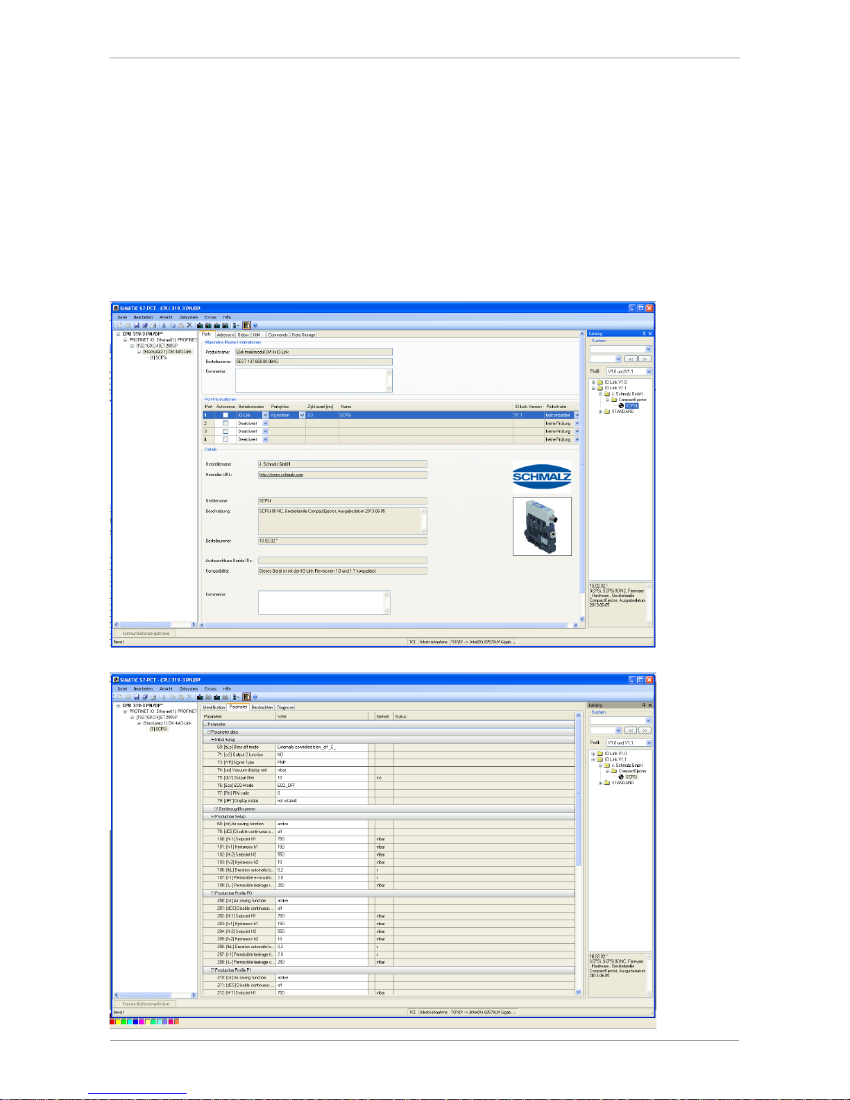
SCHMALZ SCPSI - 2
5-52
For the devices in the SCPSi series, the IODD is available to download in two versions
from www.schmalz.com:
IODD in accordance with the revision 1.1, for use with current IO-Link masters The full
range of functions is available with 4 bytes of input data and 2 bytes of output data
IODD in accordance with the revision 1.0, for use with older IO-Link masters (legacy
mode). The range of functions is slightly limited; the process data is limited to 1 byte of
input data and 1 byte of output data.
For example, when using Siemens components, the IODD for the ejector is displayed as
follows in the program S7-PCT.
Page 53
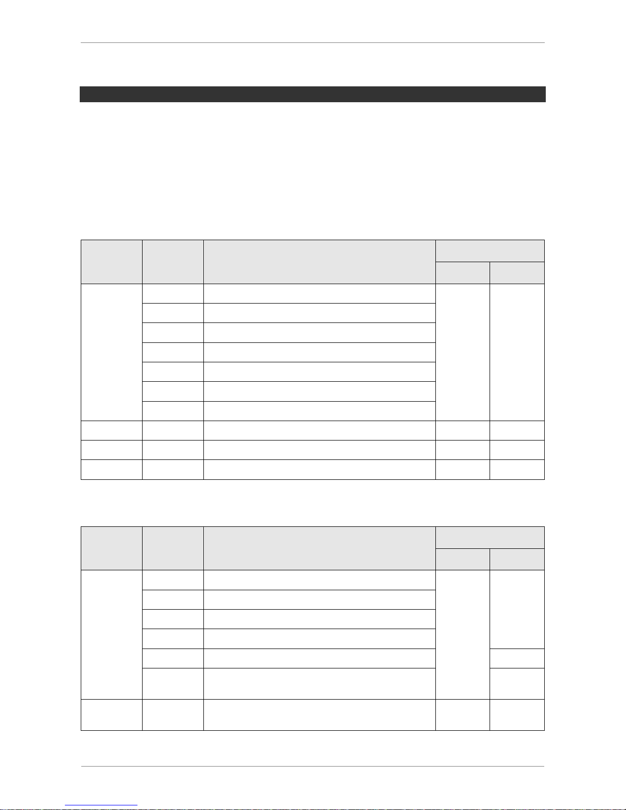
SCHMALZ SCPSI - 2
5-53
PROCESS DATA
Once communication with an IO-Link master has been established, the master begins the
automatic cyclic exchange of process data. The master receives new process output data
(PDO) from the controller or field bus level and passes this on to the ejector for control.
The feedback and measured values from the ejector are collected from the master as process input data (PDI) and forwarded to the system controller.
In the two possible IO-Link revisions 1.1 and 1.0, the process data from the ejector SCPSi
is as follows:
PROCESS DATA INPUT (PDI)
PDI Byte
Bit
Parameter
IO-Link Revision
1.1
1.0
0
0
Part present (H2)
X
X
1
Air saving function (H1)
3
CM-Autoset-Acknowledge
4
EPC-Select-Acknowledge
5
Device status - green
6
Device status - yellow
7
Device status - red
1
7…0
EPC-Word (multi purpose)
X
-
2
7…0
EPC-Word (multi purpose)…high-byte
X
-
3
7…0
EPC-Word (multi purpose)…low-byte
X
-
PROCESS DATA OUTPUT (PDO)
PDO Byte
Bit
Parameter
IO-Link Revision
1.1
1.0
0
0
Vacuum on/off
X
X
1
Activate Blow-off
2
Setting mode
3
CM Autoset
5…4
EPC-Word-function-select
-
7…6
Select Production-Setup-Profile P0-P3
(see parameters 200-238)
X
1
7…0
System pressure (value from external sensor)
(0= feature not used)
X
-
Page 54

SCHMALZ SCPSI - 2
5-54
PARAMETER DATA
In addition to the process data that is exchanged automatically, the IO-Link protocol provides an acyclical data channel for identification data, setting parameters or general feedback from the device. The available data objects are known as ISDU with IO-Link and are
uniquely addressed within a device by their index and subindex.
Controller manufacturers usually provide a specialized function module – e.g. the “IOL_CALL” module for Siemens controllers – to enable these parameters to be accessed
from a control program.
See the separate document, “SCPSi Data Dictionary”, to find out which parameter data is
offered by the ejector SCPSi and how this data is represented as ISDU objects. This
document is available to download from www.schmalz.com.
CONFIGURATION SERVER
Since revision 1.1, the IO-Link protocol has contained an automated process for transferring data when a device is replaced. During this data storage mechanism, the IO-Link
master mirrors all setting parameters for the device in a separate non-volatile memory.
When a device is swapped for a new one of the same type, the setting parameters for the
old device are automatically saved in the new device by the master.
In order for this to work with the ejector SCPSi, it must be operated on a master with IOLink revision 1.1 or higher and the data storage feature must be activated in the configuration of the IO-Link port.
A detailed description of the data storage mechanism cannot be provided here, however,
note the following practical information:
The device parameters are automatically mirrored in the master when the device is
configured using an IO-Link configuration tool such as S7-PCT.
Changes to the parameters made in the user menu on the device are automatically
mirrored in the master.
Changes to the parameters made by a control program using a function module are
not automatically mirrored in the master. In this case, mirroring can be triggered
manually by executing ISDU write access to the “System Command” parameter
with the “ParamDownloadStore” command (numerical value 5) once all the required
parameters have been changed.
To ensure that data is transferred in the correct direction when a device is replaced, it
must be ensured that the new device is restored to the factory settings before it is
connected to the IO-Link master. This can be done at any time using the function
for restoring the factory settings, for example, via the operating menu.
Page 55
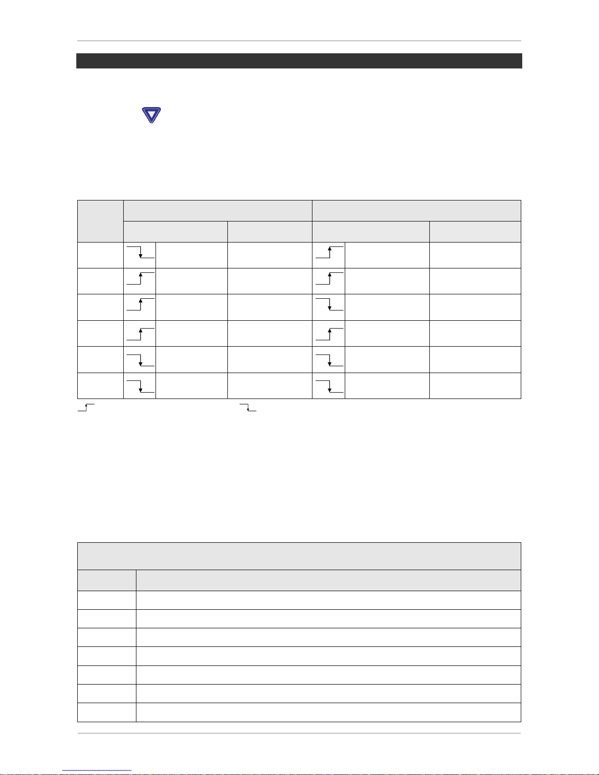
SCHMALZ SCPSI - 2
5-55
START OF OPERATIONS
The communication LED on the IO-Link master port indicates the IO-Link communication
has been successfully established.
Pressing the button displays the operating mode of the ejector.
A typical handling cycle is divided into three steps: pick-up, blow-off and the idle state.
During the pick-up step, the switching threshold H2 is monitored to determine whether a
sufficient vacuum has been established.
Step
SCPSi – xx – NO – xx
SCPSi – xx – NC – xx
Bit
State
Signal
State
1
PDO 0.0
Suction ON
PDO 0.0
Suction ON
2
PDI 0.0
Vacuum
> H2
PDI 0.0
Vacuum
> H2
3
PDO 0.0
Suction OFF
PDO 0.0
Suction OFF
4
PDO 0.1
Blow-off ON
PDO 0.1
Blow-off ON
5
PDO 0.1
Blow-off OFF
PDO 0.1
Blow-off OFF
6
PDI 0.0
Vacuum
< (H2-h2)
PDI 0.0
Vacuum
< (H2-h2)
Signal status switches from LOW to HIGH |
Signal status switches from HIGH to LOW
PDO 0.0 = BDO Byte 0 Bit 0
CONDITION MONITORING [CM]
Any condition monitoring events that occur during the suction cycle cause the system status light to immediately switch from green to yellow. The specific event that caused this
switch can be seen in the “Condition Monitoring” IO-Link parameter. The following table
shows its coding:
Coding of the condition monitoring warnings
Bit
Event
0
Valve protection function active
1
Set limit for evacuation time (t-1) exceeded
2
Set limit for leakage (-L-) exceeded
3
Threshold value H1 not reached
4
Dynamic pressure > (H2-h2) and < H1
5
Supply voltage outside the operating range
7
System pressure outside of working range
Page 56

SCHMALZ SCPSI - 2
5-56
The four bits with the lowest values describe events that can only occur once per suction
cycle. They are reset at the start of every suction cycle and remain stable until after suctioning has finished.
Bit number 4, which describes excessive dynamic pressure, is initially deleted when the
device is switched on and is only updated when a dynamic pressure value is detected
again.
Bits 5 and 7 are permanently updated independently of the suction cycle and reflect the
current values for the supply voltage and system pressure.
The measurement values for condition monitoring – the evacuation times t0 and t1 as well
as the leakage area – are reset at the start of every suction cycle and updated at the point
in time when they can be measured.
ENERGY MONITORING [EM]
The measurement value for the absolute air consumption (Air consumption per cycle) is
reset at the start of every suction cycle and then permanently updated during the cycle. It
can continue to change until after the end of blow-off.
To determine the other EM values – air consumption in percent and electrical energy consumption – the neutral phase of the suction cycle must also be taken into consideration.
Therefore, the measurement values can only be updated once the next suction cycle starts
and thus show the result of the previous cycle during the complete cycle.
PREDICTIVE MAINTENANCE [PM]
The measurement value for the leakage rate and the related quality assessment in percent
are reset at the start of every suction cycle and permanently updated during the cycle as
moving averages. The values therefore remain stable until after the suction cycle is complete.
The dynamic pressure (vacuum during unobstructed intake) and the related performance
assessment in percent are initially unknown when the ejector is switched on. As soon as a
dynamic pressure measurement can be performed, they are updated and retain their values until the next dynamic pressure measurement.
Page 57
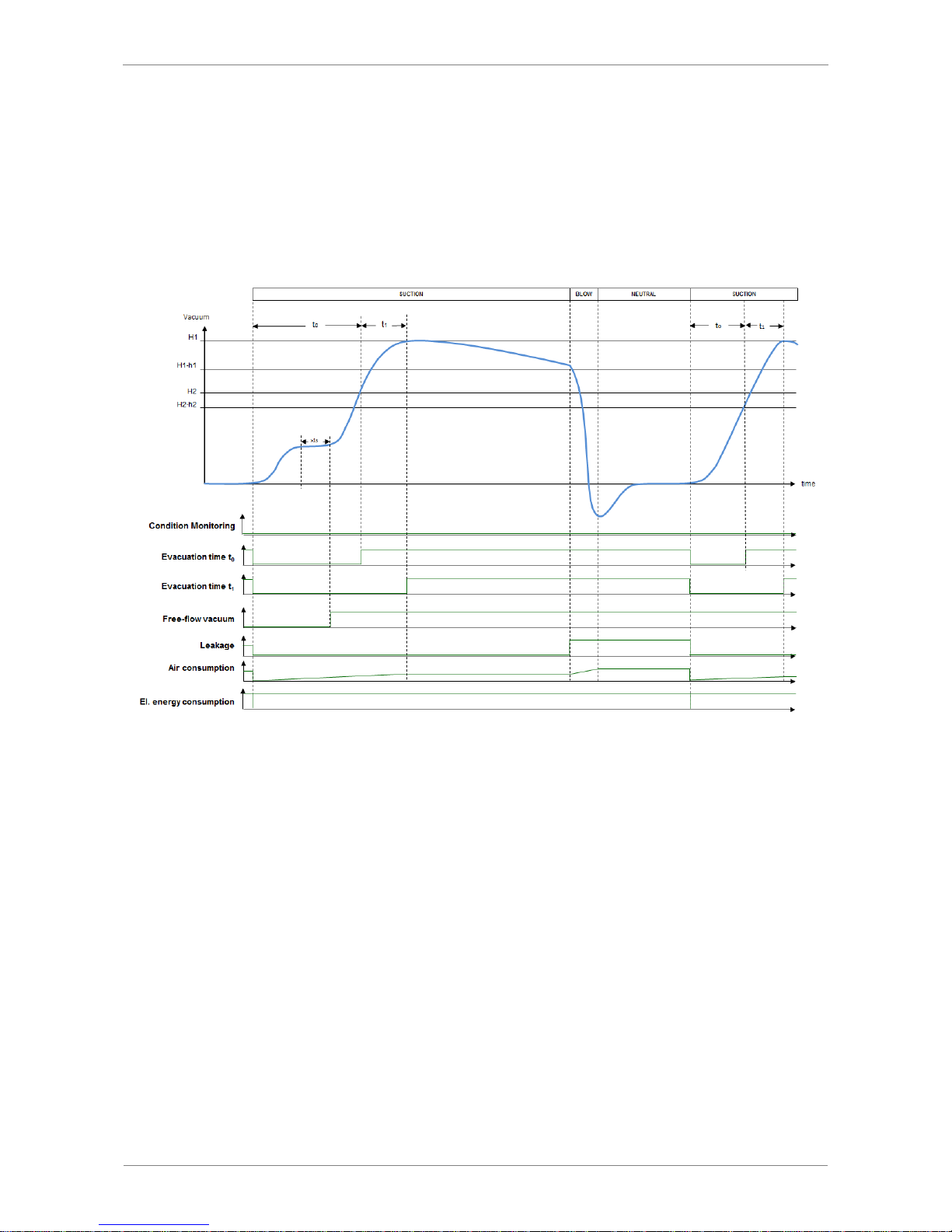
SCHMALZ SCPSI - 2
5-57
TYPICAL SUCTION CYCLES
The following diagrams show some typical vacuum curves during a suction cycle and
show the points at which EPC values could be updated.
Handling cycle with dynamic pressure measurement and average leakage
Page 58
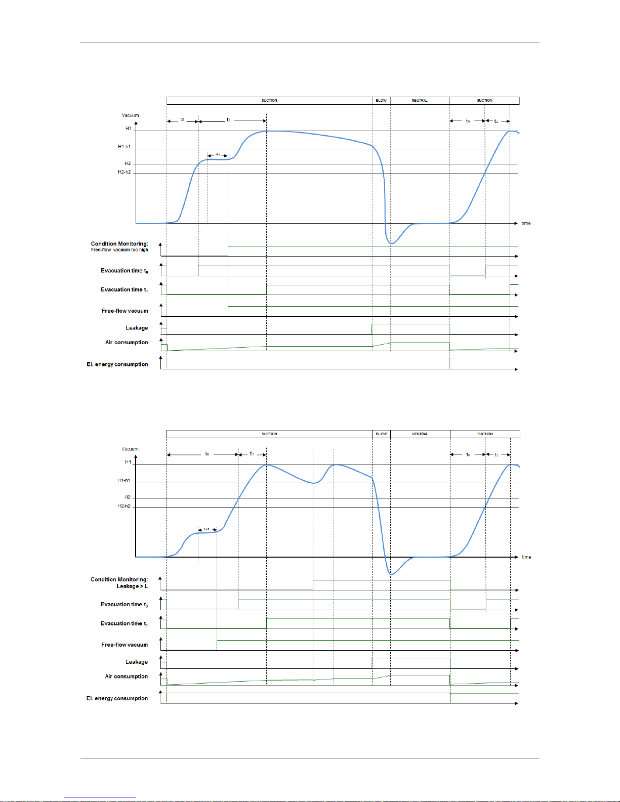
SCHMALZ SCPSI - 2
5-58
Handling cycle with dynamic pressure measurement and excessive leakage
Handling cycle with leakage > L and readjustment
Page 59
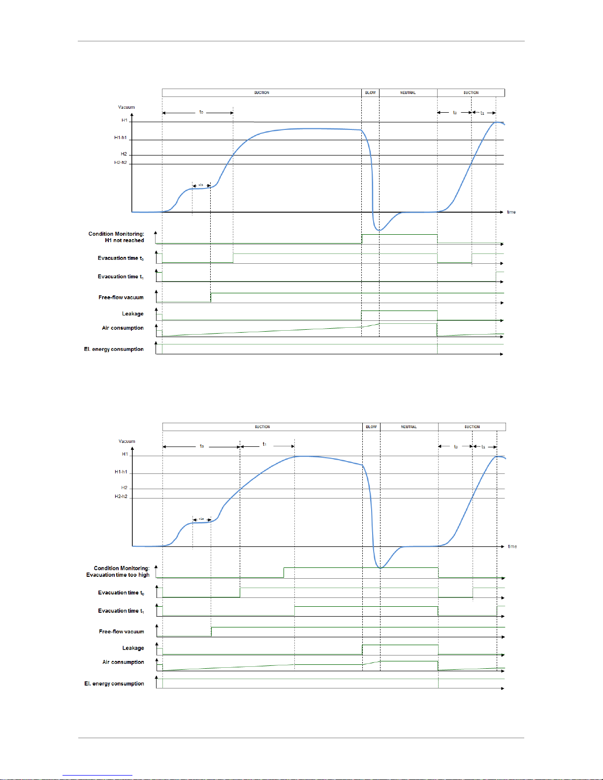
SCHMALZ SCPSI - 2
5-59
Handling cycle with very high leakage (H1 is not reached)
Handling cycle with excessive evacuation time t1
Page 60
SCHMALZ SCPSI - 2
5-60
SYSTEM STATUS LIGHT
The overall status of the ejector system is displayed as a traffic light using 3 bits of process
data input byte 0. All warnings and errors are used to determine the status shown here.
This basic display provides immediate information about the status of the ejector with all its
input and output parameters.
System status displayed
Overall ejector system status
Green system status
System is working perfectly with optimal operating parameters
Yellow system status
Warning – The ejector system is not working optimally;
please check the operating parameters
(Condition monitoring warnings have occurred)
Red system status
Error – Safe operation of the ejector within the operating
limits is no longer ensured
(Error code is available in the error parameter)
WARNINGS AND ERRORS
Coding of the condition monitoring warnings
Bit
Event
0
Valve protection function active
1
Set limit for evacuation time (t-1) exceeded
2
Set limit for leakage (-L-) exceeded
3
Threshold value H1 not reached
4
Dynamic pressure > (H2-h2) and < H1
5
Supply voltage outside the operating range
7
System pressure outside of working range
Code
Description
E01
Electronics error – internal data management
E02
Electronics error – internal communication
E03
Zero-point adjustment for vacuum sensor outside ± 3% FS
E07
Supply voltage is too low
E08
IO-Link communication error
E17
Supply voltage is too high
E18
Operating pressure is too high or too low (with externally supplied pressure
value)
Page 61
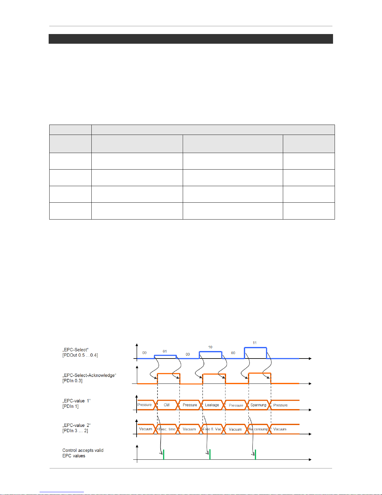
SCHMALZ SCPSI - 2
5-61
EPC-VALUES IN THE PROCESS DATA
To quickly and conveniently capture the most important results from the condition monitoring [CM], energy monitoring and predictive maintenance functions, these are also made
available via the process input data of the device. The top 3 bytes of the process output
data are also configured as a multifunctional data range, consisting of an 8 bit value (“EPC
Value 1”) and a 16 bit value (“EPC Value 2”).
The current content of this data supplied by the ejector can be changed via the process
output data using the 2 bits “EPC-Select”. The four possible ways in which this data is configured is listed in the following table:
PDO
PDI
EPC-Select
EPC-Value 1 (8-Bit)
EPC- Value 2 (16-Bit)
EPC-SelectAcknowledge
00
Current input pressure
(Unit 0,1 bar)
Current Vacuum level
(Unit 1 mbar)
0
01
Condition Monitoring
Evacuation time t
1
(Unit 1 ms) 1
10
Leakage rate
(Unit 1 mbar/s)
Last measured dynamic pressure
(Unit 1 mbar)
1
11
Supply voltage
(Unit 0,1 V)
Air consumption
(Unit 0,1 NL)
1
The switch is made depending on the structure of the automation system with some time
delay. However, in order to be able to read the different pairs of values efficiently though a
controller program, the bit EPC-Select-Acknowledge is provided in the process input data.
The bit always accepts the values shown in the table. In order to read out all EPC values,
the procedure illustrated in the following diagram is recommended:
Always start with EPC-Select = 00 and create the selection for the next value pair required,
e.g. EPC-Select = 01. Now wait until the bit EPC-Select-Acknowledge changes from 0 to
1. This signifies that the values transmitted match the selection created and they can be
accepted by the controller.
Now, switch back to EPC-Select = 00 and wait until the bit EPC-Select-Acknowledge is
reset to 0 by the ejector. The process for the next value pair, e.g. EPC-Select = 10, can
then be performed in the same way, and so on.
Page 62

SCHMALZ SCPSI - 2
6-62
6 MAINTENANCE
GENERAL MAINTENANCE
EXTERIOR SOILING
Remove dirt on the exterior of the device with a soft cloth and soap suds (max. 60°C). Ensure that the silencer and the controller are not soaked with soap suds.
SILENCER
Because it is open, the silencer may be exposed to high levels of dust, oil, etc., which may
dirty the silencer to the point of reducing the suction capacity. If this happens, it must be
replaced. Cleaning is not recommended due to the capillary effect of the porous material.
PRESS-IN SCREENS
The vacuum and compressed air connections include press-in screens.
Over time, dust, chips and other solids can become deposited in the screens.
If you notice that the performance of the ejector system has declined, simply replace the
screens.
Do not operate the ejector system without the screens. This can damage the
ejector system.
WARRANTY, SPARE PARTS AND WEARING PARTS
This system is guaranteed in accordance with our general terms of trade and delivery. The
same applies to spare parts, provided that these are original parts supplied by us.
We are not liable for any damage resulting from the use of non-original spare parts or accessories.
Wearing parts are not covered by the warranty.
The following list contains the primary spare and wearing parts.
Legend: - Spare part= S
- Wearing part= W
Page 63
SCHMALZ SCPSI - 2
6-63
SPARE AND WEARING PARTS
Type
Designation
Article no.
Legend
Silencer insert
10.02.02.04141
W
Screen
10.02.02.04404
S
TROUBLESHOOTING
Störung
mögliche Ursache
Abhilfe
Vacuum level is
not reach or vacuum is created too
slowly
Press-in screen in contami-
Replace the screen
Silencer is dirty
Replace silencer
Leakage in hose line
Check hose connections
Leakage at suction pad
Check suction pad
Operating pressure too low
Increase operating pressure (observe max.
limits)
Internal diameter of hose
lines too small
See recommended hose diameters
Payload cannot be
held securely
Vacuum level too low
Increase the control range if the air-saving
function is activated
Suction pad too small
Select a larger suction pad
Display shows
an error code
See “Error codes”
table
See “Error codes”
table
ACCESSORIES
Designation
Article no.
M12 connection cable, 5-pin, with open end, 5 m
21.04.05.00080
M12 connection cable, 5-pin, to 5-pin M12 plug, 1 m
10.02.02.00158
M12 connection distributor, 5-pin, to 2xM12, 4-pin
10.02.02.03490
Top-hat rail clamp for TS35 top-hat rail, incl. plastic tapping screws
(optional)
10.02.02.04139
Page 64
SCHMALZ SCPSI - 2
7-64
7 TECHNICAL DATA
Operating the ejector system outside of the specified values can result in damage to the
system and attached components.
ELECTRICAL PARAMETERS
Parameter
Sym-
bol
Limit values
Units
Comment
Min.
Typ.
Max.
Supply voltage
U
S/A
19,2
24
26,4
VDC
PELV 1)
SCPSi – xx – xx – NO – M12
Rated current from U
S/A
2)
I
S/A
50 4)
120
mA
U
S/A
= 24,0V
SCPSi – xx – xx – NC – M12
Rated current from U
S/A
2)
I
S/A
40 4)
70
mA
U
S/A
= 24,0V
Voltage of signal output (PNP)
UOH
U
S/SA
-2
V
S/SA
VDC
IOH < 140 mA
Voltage of signal output (NPN)
UOL
0 2
VDC
IOL < 140 mA
Current of signal output (PNP)
IOH
140
mA
Short-circuit-proof 3)
Current of signal output (NPN)
IOL
-140
mA
Short-circuit-proof 3)
Voltage of signal input (PNP)
UIH
15
U
A//SA
VDC
Relative to Gnd
A/SA
Voltage of signal input (NPN)
UIL
0 9
VDC
Relative to U
A/SA
Current of signal input (PNP)
IIH 5 mA
Current of signal input (NPN)
IIL -5 mA
Reaction time of signal inputs
tI 3 ms
Reaction time of signal output
tO
1 200
ms
adjustable
1)
The power supply must comply with the requirements of EN60204 (protective extra-low voltage).
The power supply, signal inputs and signal outputs are all protected against reverse polarity.
2)
Plus the output currents
3)
The signal output is protected against short circuits. However, the signal output is not secured against overloading.
Constant load currents of > 0.15 A can lead to unacceptable heat levels and subsequent destruction of the ejector.
4)
Average
Page 65
SCHMALZ SCPSI - 2
7-65
DISPLAY PARAMETERS
Parameter
Value
Unit
Comment
Display
3
Digits
Red 7-segment LED
Resolution
2
mbar
Accuracy
3
% FS
T
amb
= 25 °C, based on FS end value (full scale)
Linearity error
1
%
Offset error
2
mbar
After zero-point adjustment, without vacuum (unit = mbar)
Temperature influence
3
%
0 °C < T
amb
< 50°C
Display refresh rate
5
1/s
This only affects the red 7-segment display (see the
“Electrical parameters” section for signal inputs and outputs).
Idle time before the
menu is exited
2
min
If no settings are made in a menu, the ejector automatically returns to display mode.
MECHANICAL DATA
GENERAL PARAMETERS
Parameter
Symbol
Limit values
Unit
Comment
Min.
Typ
Max.
Ambient temperature
T
amb
0 50
°C
Storage temperature
T
Sto
-10 60
°C
Humidity
H
rel
10 90
%rf
Free from condensation
Degree of protection
IP65
Operating pressure
P 2 4 6 bar
Operating medium
Air or neutral gas, filtered to 5 µm, oiled or unoiled, compressed air w/ quality class 3-3-3 acc. to ISO 8573-1
Page 66
SCHMALZ SCPSI - 2
7-66
MATERIALS USED
Component
Material
Basic body
PA6-GF
Inner components
Anodized aluminum, Anodized aluminum alloy, brass,
galvanized steel, stainless steel, PU, POM
Controller housing
PC-ABS
Silencer insert
PE porous
Seals
NBR
Lubricants
Silicone-free
Screws
Galvanized steel
MECHANICAL PARAMETERS
Type
Nozzle
size
Max.
vacuum2
Suction
rate1
Max. blowoff capacity1
Air consumption1
Sound level1
Weight
Free
sucking
sucked
mm
mbar
l/min
l/min
l/min
dBA
dBA
kg
SCPSi-2-07
0,7
870
32
115
24
67
58
0,195
SCPSi-2-09
0,9
870
45
115
40
72
59
0,195
SCPSi-2-14
1,4
870
67
115
82
78,5
70
0,195
1)
at 4 bar 2) at optimum pressure
Page 67
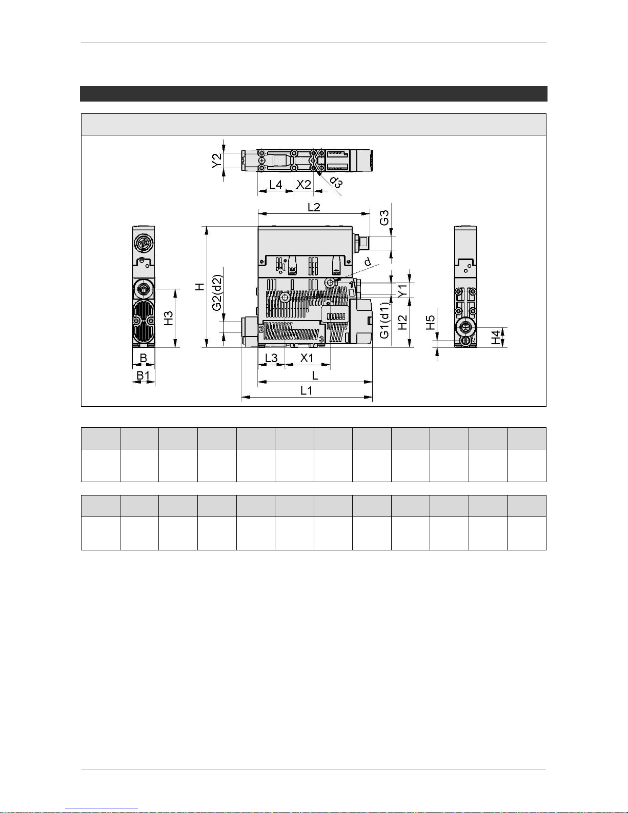
SCHMALZ SCPSI - 2
7-67
DIMENSIONS
SCPSi 2…
B
B1 d d1
d2 1
d3
G1
G2
G3 H H2
H3
18
18,6
4,4 6 6 / 8
2,6
G1/8”IG
G1/8”IG
M12x1
-AG
99
40,8
47,5
H4
H5 L L1
L2
L3
L4
X1
X2
Y1
Y2
16,5
5,5
93,8
107,1
91,5
22
29,5
36,9
16
12
12
1)
Only with plug-in hose connector All dimensions in mm
Page 68
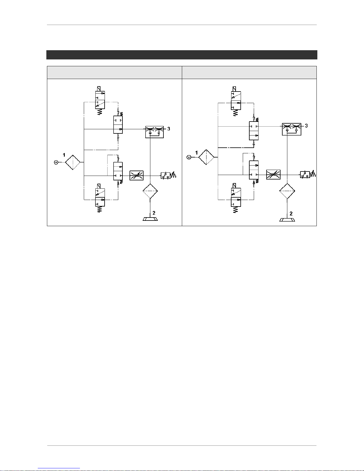
SCHMALZ SCPSI - 2
7-68
PNEUMATIC CIRCUIT DIAGRAMS
SCPSi 2...NO...
SCPSi 2...NC...
Page 69
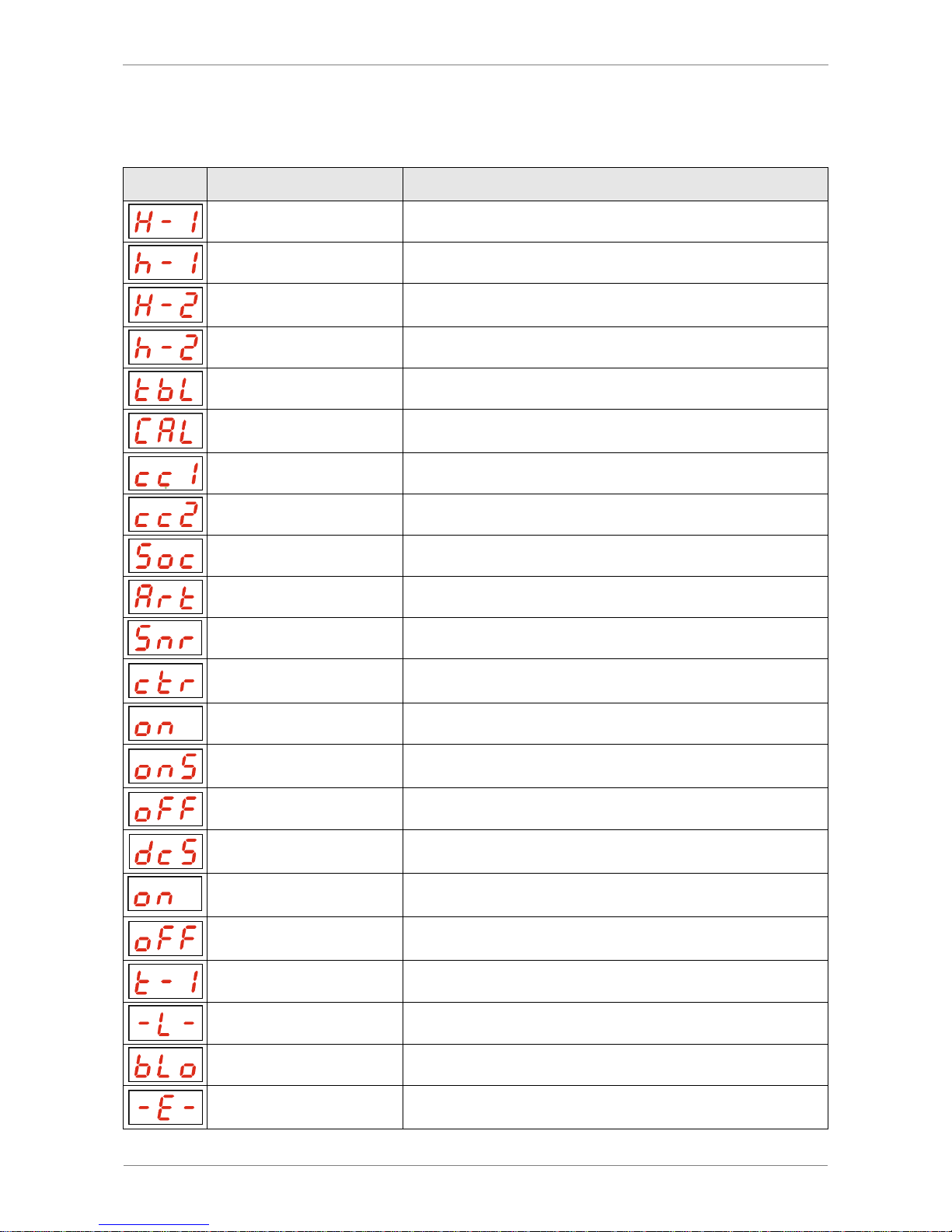
SCHMALZ SCPSI - 2
7-69
OVERVIEW OF DISPLAY SYMBOLS
Symbol
Function
Comment
Switching point H1
Switch-off value for the air-saving function
Hysteresis h1
Hysteresis of the air-saving function
Switching point H2
Switch-on value for the “part present control” signal output
(when NO output is configured)
Hysteresis h2
Hysteresis of “part present control” signal output
Blow-off time
Blow-off time setting for time-controlled blow-off
Zero-point adjustment
(calibrate)
Calibrating the vacuum sensor
Counter 1
Counter for suction cycles (suction signal input)
Counter 2
Counter for valve switching frequency
Software version
Displays the current software version
Article number
Displays the article number of the ejector
Serial number
Displays the serial number of the ejector
Air-saving function
(control)
Setting for the air-saving function
Air-saving function on
Activation of the air-saving function
Air-saving function on
with leakage monitoring
Switching on the air-saving function with leakage monitoring
Air-saving function off
Deactivation of the air-saving function
Deactivate continuous
suction
Enabling continuous suction
Continuous suction is
deactivated
Continuous suction option is deactivated
Continuous suction is
activated
Continuous suction option is activated
Evacuation time
Setting for the maximum permitted evacuation time
Leakage value
Setting for the maximum permitted leakage
Blow-off function
Menu for configuring the blow-off function
“External” blow-off
Selection of externally controlled blow-off (external signal)
Page 70
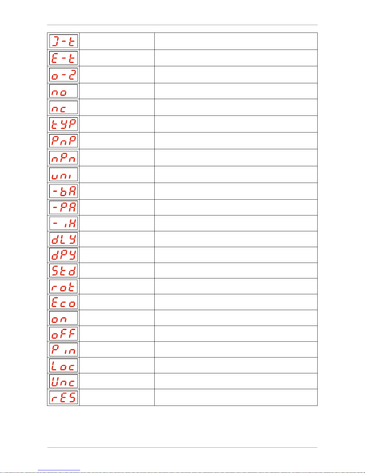
SCHMALZ SCPSI - 2
7-70
“Internal” blow-off
Selection of internally controlled blow-off (triggered internally; time can be set)
“Externally timecontrolled” blow-off
Selection of externally controlled blow-off (triggered externally; time can be set)
Configuration of the
signal output
Menu for configuring the signal output
Normally open contact
Setting the signal output as a normally open contact
Normally closed
contact
Setting the signal output as a normally closed contact
Configuration of
signal type
Menu for configuring the signal type (NPN/PNP)
PNP signal type
All input and output signals switch according to PNP
(input/output on = 24 V)
NPN signal type
All input and output signals switch according to NPN
(input/output on = 0 V)
Vacuum unit
Vacuum unit in which the measurement and setting values are displayed
Vacuum value in mbar
The vacuum and pressure values are displayed
in mbar.
Vacuum value (in kPa)
The vacuum and pressure values are displayed in kPa.
Vacuum value in inHg
The vacuum and pressure values are displayed in inHg.
Switch-off delay
Setting for the switch-off delay for OUT1 and OUT2
Display rotation
Setting the display position (rotation)
Default display
Display is not rotated
Rotated display
Display is rotated by 180°
ECO mode
Configuring ECO mode
ECO mode on
ECO mode is activated – the display switches off
Not in ECO mode
ECO mode is deactivated – the display remains on
PIN
Enter the PIN to unlock the menu
Menu locked
A lock prevents parameters from being changed.
Menu unlocked
The buttons and menus are unlocked.
Reset
All values that can be changed are reset to the factory
settings.
Page 71
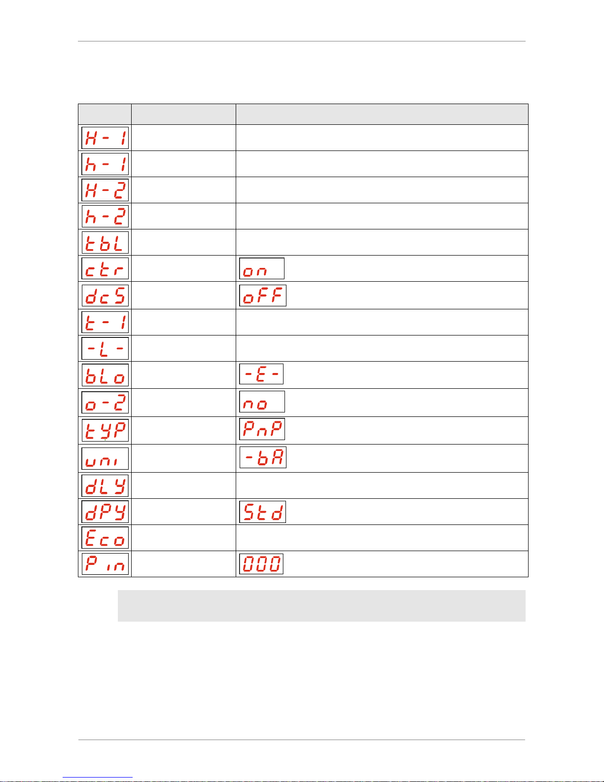
SCHMALZ SCPSI - 2
7-71
FACTORY SETTINGS
Symbol
Function
Factory setting
Switching point H1
750 mbar
Hysteresis h1
150 mbar
Switching point H2
550 mbar
Hysteresis h2
10 mbar
Blow-off time
0,20 s
Air-saving function
Deactivate continuous suction
Evacuation time
2 s
Leakage value
250 mbar/s
Blow-off function
Externally controlled blow-off
Configuration of the
signal output
Normally open contact)
Signal type
PNP switching
Vacuum unit
Vacuum unit (in mbar)
Switch-off delay
10 ms
Display rotation
ECO mode
oFF
PIN-Code
The production setup profiles P-1 to P-3 are factory-set to have the exact same
data set as the default data set P-0.
Page 72

SCHMALZ SCPSI - 2
8-72
8 CONFORMITY DECLARATION
Page 73

SCHMALZ SCPSI - 2
8-73
Page 74

SCHMALZ SCPSI - 2
8-74
Visit us online:
Schmalz online – www.schmalz.com
These operating instructions were originally written in German and have been translated
into English.
We reserve the right to make technical changes. No responsibility is taken for print errors
or other types of errors.
All information and specifications are subject to change without notice.
© J. Schmalz GmbH. All rights reserved.
Page 75

Schmalz worldwide
Canada
Tel.+1 905 569 9520
Fax+1 905 569 8256
[email protected]
China
Tel.+86 21 5109 9933
Fax+86 21 5039 8882
[email protected]
Finland
Tel.+358 9 85746 92
Fax+358 9 85746 94
[email protected]
France
Tel.+33 (0) 1 6473 1730
Fax+33 (0) 1 6006 6371
[email protected]
India
Tel.+91 (0) 20 4072 5500
Fax+91 (0) 20 4072 5588
[email protected]
Italy
Tel. +39 0321 621510
Fax +39 0321 621714
[email protected]
Japan
Tel. +81 45 308 9940
Fax +81 45 308 9941
[email protected]
Netherlands
Tel. +31 (0)74 255 5757
Fax +31 (0)74 255 5758
[email protected]
Poland
Tel. +48 (0)22 46 04970
Fax +48 (0)22 87 40062
[email protected]
Russia
Tel. +7 495 9671248
Fax +7 495 9671249
[email protected]
Spain
Tel. +34 94 4805585
Fax +34 94 4807264
[email protected]
South Korea
Tel.+82 31 8162403
Fax+82 31 8162404
[email protected]
Switzerland
Tel.+41 44 88875 25
Fax+41 44 88875 29
[email protected]
Turkey
Tel.+90 216 3400121
Fax+90 216 3400124
[email protected]
USA
Tel.+1 919 7130880
Fax+1 919 7130883
[email protected]
30.30.01.00762_EN
Index: 02 Status: 03/2017
J. Schmalz GmbH
Aacher Strasse 29
D-72293 Glatten
Tel. +49 (0)7443 2403 0
Fax +49 (0)7443 2403 259
[email protected]
www.schmalz.com
 Loading...