


Compaktejector SCPi FS RP
Operating Instructions
WWW.SCHMALZ.COM EN-US · 30.30.01.01602 · 01 · 10/18

Note
The operating instructions were originally written in German and have been translated into English. Store
in a safe place for future reference. Subject to technical changes without notice. No responsibility is taken
for printing or other types of errors.
Published by
© J.SchmalzGmbH, 10/18
This document is protected by copyright. J.SchmalzGmbH retains the rights established thereby. Reproduction of the contents, in full or in part, is only permitted within the limits of the legal provisions of
copyright law. Any modifications to or abridgments of the document are prohibited without explicit written agreement from J.SchmalzGmbH.
Contact
J. Schmalz GmbH
Johannes-Schmalz-Str. 1
72293 Glatten, Germany
T: +49 7443 2403-0
schmalz@schmalz.de
www.schmalz.com
Contact information for Schmalz companies and trade partners worldwide can be found at:
www.schmalz.com/salesnetwork
2 / 58 EN-US · 30.30.01.01602 · 01 · 10/18

Contents
EN-US · 30.30.01.01602 · 01 · 10/18 3 / 58
Contents
1 Important information ...................................................................................................................................7
1.1 Note on using these operating instructions ......................................................................................... 7
1.2 The technical documentation is part of the product ........................................................................... 7
1.3 Warnings in this document.................................................................................................................... 7
1.4 Symbol..................................................................................................................................................... 7
2 Fundamental Safety Instructions...................................................................................................................8
2.1 Standards of Technology ....................................................................................................................... 8
2.2 Emissions ................................................................................................................................................. 8
2.3 Intended Use........................................................................................................................................... 8
2.4 Non-Intended Use .................................................................................................................................. 8
2.5 Personnel Qualification.......................................................................................................................... 9
2.6 Modifications to the Ejector .................................................................................................................. 9
3 Product description.......................................................................................................................................10
3.1 Description of the Ejector .................................................................................................................... 10
3.1.1 Suction of the Workpiece (Vacuum Generation) .................................................................... 10
3.1.2 Depositing the Workpiece (Blowing Off) ................................................................................ 10
3.1.3 Pneumatic Air Saving Function................................................................................................. 11
3.2 Operating Modes ................................................................................................................................. 11
3.3 Ejector Designation .............................................................................................................................. 11
3.4 Ejector Structure................................................................................................................................... 12
3.5 Display and Operating Element in Detail ........................................................................................... 13
4 Technical Data ...............................................................................................................................................14
4.1 Display Parameters ............................................................................................................................... 14
4.2 Electrical Parameters ............................................................................................................................ 14
4.3 General Parameters.............................................................................................................................. 15
4.4 Mechanical Data................................................................................................................................... 15
4.4.1 Performance Data...................................................................................................................... 15
4.4.2 Factory Settings ......................................................................................................................... 15
4.4.3 Dimensions................................................................................................................................. 16

Contents
4 / 58 EN-US · 30.30.01.01602 · 01 · 10/18
4.4.4 Pneumatic Circuit Plan .............................................................................................................. 17
5 General Description of Functions ................................................................................................................18
5.1 Digital Switching Outputs (SIO)........................................................................................................... 18
5.2 IO-Link................................................................................................................................................... 18
5.3 Operating and Menu Concepts ........................................................................................................... 19
5.3.1 Navigating in the Menu ............................................................................................................19
5.3.2 Enabling Vacuum Switches and Editing Parameters ...............................................................19
5.3.3 Displaying the Basic Settings (Slide Show)............................................................................... 20
5.3.4 Basic Menu .................................................................................................................................21
5.3.5 Extended Functions Menu (EF) .................................................................................................22
5.3.6 Info menu (INF).......................................................................................................................... 23
5.4 Error Display ......................................................................................................................................... 24
6 Transport and storage ..................................................................................................................................25
6.1 Checking the Delivery .......................................................................................................................... 25
7 Installation.....................................................................................................................................................26
7.1 Installation Instructions........................................................................................................................ 26
7.2 Installation ............................................................................................................................................ 26
7.3 Pneumatic Connection ......................................................................................................................... 27
7.3.1 Connecting the Compressed Air and Vacuum .........................................................................27
7.3.2 Instructions for the Pneumatic Connection .............................................................................28
7.4 Electrical Connection............................................................................................................................ 28
7.4.1 Operating the Vacuum Switch in SIO Mode ............................................................................30
7.4.2 Operating the Vacuum Switch in IO-Link Mode...................................................................... 30
8 Functions of the Vacuum Switch .................................................................................................................31
8.1 Overview of Functions ......................................................................................................................... 31
8.2 Monitoring the Operating Voltage..................................................................................................... 32
8.3 Switching Points ................................................................................................................................... 32
8.3.1 Switching Point Mode and Switching Point Logic................................................................... 32
8.3.2 Two-Point Mode ........................................................................................................................32
8.3.3 Window Mode ...........................................................................................................................33

Contents
EN-US · 30.30.01.01602 · 01 · 10/18 5 / 58
8.3.4 Condition Monitoring Mode (Leakage Measurement)........................................................... 33
8.3.5 Diagnostics Mode ......................................................................................................................34
8.4 Teach-in for Switching Points .............................................................................................................. 34
8.5 Additional Switching Point Settings ................................................................................................... 35
8.5.1 Switch-on and Switch-off Delay ............................................................................................... 35
8.5.2 Transistor Function ....................................................................................................................35
8.6 Display Screen....................................................................................................................................... 35
8.6.1 Vacuum Unit ..............................................................................................................................35
8.6.2 Display Alignment .....................................................................................................................36
8.6.3 ECO Mode ..................................................................................................................................36
8.7 Access Rights......................................................................................................................................... 36
8.7.1 PIN Code for Write Protection ..................................................................................................36
8.7.2 IO-Link Device Access Locks ...................................................................................................... 36
8.8 Device Identification ............................................................................................................................ 37
8.9 User-Specific Localization .................................................................................................................... 37
8.10 System Monitoring and Diagnostics.................................................................................................... 37
8.10.1 Minimum and Maximum Values............................................................................................... 37
8.10.2 Counters ..................................................................................................................................... 37
8.10.3 Status Signals .............................................................................................................................38
8.10.4 Leakage Measurement .............................................................................................................. 38
8.11 System Commands................................................................................................................................ 38
8.11.1 Resetting to Factory Settings .................................................................................................... 38
8.11.2 Calibrating the Vacuum Sensor ................................................................................................39
9 Operation ......................................................................................................................................................40
9.1 General Preparations ........................................................................................................................... 40
10 Troubleshooting............................................................................................................................................ 41
10.1 Help with Malfunctions ....................................................................................................................... 41
10.2 List of Error Numbers ........................................................................................................................... 42
10.3 Warnings and Error Messages in IO-Link Mode ................................................................................. 43
11 Maintenance.................................................................................................................................................. 44

Contents
6 / 58 EN-US · 30.30.01.01602 · 01 · 10/18
11.1 Safety .................................................................................................................................................... 44
11.2 Cleaning the Ejector............................................................................................................................. 44
11.3 Replacement of the Device with a Parameterization Server ............................................................. 44
12 Warranty........................................................................................................................................................ 46
13 Spare and Wearing Parts, Accessories......................................................................................................... 47
13.1 Spare and Wearing Parts ..................................................................................................................... 47
13.2 Accessories ............................................................................................................................................ 47
14 Decommissioning and recycling ..................................................................................................................48
14.1 Disposing of the Ejector....................................................................................................................... 48
14.2 Materials Used ...................................................................................................................................... 48
15 Appendix .......................................................................................................................................................49
15.1 SCPi_CE_30.30.01.01667-00.pdf ........................................................................................................... 50
15.2 SCPi_Data Dictionary_01.pdf ............................................................................................................... 51
16 Notes..............................................................................................................................................................57

Important information
EN-US · 30.30.01.01602 · 01 · 10/18 7 / 58
1Important information
1.1Note on using these operating instructions
The J.SchmalzGmbH is generally referred to as Schmalz in these operating instructions.
These operating instructions contain important notes and information about the different operating
phases of the product:
• Transport, storage, start of operations and decommissioning
• Safe operation, required maintenance, rectification of any faults
The operating instructions describe the product at the time of delivery by Schmalz.
1.2The technical documentation is part of the product
1. For problem-free and safe operation, follow the instructions in the documents.
2. Keep the technical documentation in close proximity to the product. The documentation must be accessible to personnel at all times.
3. Pass on the technical documentation to subsequent users.
ð Schmalz is not liable for damage or malfunctions that result from failure to heed these instructions.
If you still have questions after reading the technical documentation, contact the Customer Service Center
on:
www.schmalz.com/services
1.3Warnings in this document
Warnings warn against hazards that may occur when handling the product. This document contains three
levels of danger that you can recognize by the signal word.
Signal word Meaning
WARNING Indicates a medium-risk hazard which, if not avoided, could result in death or
serious injury.
CAUTION Indicates a low-risk hazard which, if not avoided, could result in minor or
moderate injury.
NOTE Indicates a danger that leads to property damage.
1.4Symbol
This sign indicates useful and important information.
ü This symbol represents a prerequisite that must be met before installation and maintenance work.
4 This sign represents an action to be performed.
ð This sign represents the result of an action.
Actions that consist of more than one step are numbered:
1. First action to be performed.
2. Second action to be performed.

Fundamental Safety Instructions
8 / 58 EN-US · 30.30.01.01602 · 01 · 10/18
2Fundamental Safety Instructions
2.1Standards of Technology
The ejector is built in accordance with the latest standards of technology and is shipped safely, however,
hazards can arise during use.
WARNING
Failure to follow the instructions in this manual can lead to life-threatening injuries!
4 Read the operating instructions carefully and observe the contents.
2.2Emissions
The ejector emits noise due to the operation of compressed air.
WARNING
Noise pollution due to the escape of compressed air
Hearing damage!
4 Wear ear protectors.
4 The ejector must only be operated with a silencer.
2.3Intended Use
The ejector is designed to generate a vacuum for gripping and transporting objects when used in conjunction with suction cups. Operation is via a controller using external solenoid valves.
Neutral gases are approved as evacuation media. Neutral gases include air, nitrogen and inert gases (e.g.
argon, xenon and neon).
The product is intended for industrial use.
Intended use includes the observance of the technical data and the installation and operating instructions
in this manual.
2.4Non-Intended Use
WARNING
Extraction of hazardous media, liquids or bulk material
Personal injury or damage to property!
4 Do not extract harmful media such as dust, oil mists, vapors, aerosols etc.
4 Do not extract aggressive gases or media such as acids, acid fumes, bases, biocides, dis-
infectants or detergents.
4 Do not extract liquids or bulk materials, e.g. granulates.
Schmalz accepts no liability for damages caused by non-intended usage of the ejector. In particular, the
following are considered non-intended use:
• Use in potentially explosive atmospheres
• Use in medical applications
• Lifting people or animals

Fundamental Safety Instructions
EN-US · 30.30.01.01602 · 01 · 10/18 9 / 58
• Evacuation of objects that are in danger of imploding
2.5Personnel Qualification
Unqualified personnel cannot recognize dangers and are therefore exposed to higher risks!
1. Only instruct qualified personnel to perform the tasks described in this manual.
2. The product may only be operated by persons who have undergone appropriate training.
3. Electrical work and installations may only be carried out by qualified electrical specialists.
4. Assembly and maintenance work may only be carried out by qualified personnel.
The following target groups are addressed in this manual:
• Installers who are trained in handling the product and can operate and install it
• Technically trained service personnel performing the maintenance work
• Technically trained persons who work on electrical equipment
2.6Modifications to the Ejector
Schmalz assumes no liability for consequences of modifications over which it has no control:
1. The ejector must be operated only in its original condition as delivered.
2. Use only original spare parts from Schmalz.
3. The ejector must be operated only in perfect condition.

Product description
10 / 58 EN-US · 30.30.01.01602 · 01 · 10/18
3Product description
3.1Description of the Ejector
3.1.1Suction of the Workpiece (Vacuum Generation)
The Venturi nozzle on the ejector is activated and deactivated using the Suction command.
In the NO (normally open) version, the Venturi nozzle is continuously sucking. As soon as compressed air is
present at the ejector, the Venturi nozzle becomes active and the ejector generates a vacuum (suction). As
soon as there is no compressed air at the ejector, the Venturi nozzle is deactivated.
An integrated sensor records the vacuum generated by the Venturi nozzle. The value is evaluated using
electronics, displayed via the display and output via the IO-Link process data. The measured value serves
as the basis for the various condition monitoring analysis functions in IO-Link mode.
The ejector has an integrated, pneumatically controlled, air saving function and automatically regulates
the vacuum in Suction mode:
• The integrated, pneumatically controlled, air saving function switches off the Venturi nozzle as soon
as the set vacuum limit value, deactivation value A, has been reached (factory setting).
• When objects with dense surfaces are picked up, the integrated non-return valve prevents the vacuum from dropping.
• If the system vacuum drops below the activation limit value E due to leaks, the Venturi nozzle is
switched back on.
• Depending on the vacuum, the switching point SP1 is set once a workpiece is picked up safely. This
enables the further handling process.
• The enable signal is only reset when rP1 is not reached (> See ch. 3.1.3).
The air saving function is integrated in the ejector via a pneumatic controller. The limit values A and E
cannot be changed.
The display and the LED status display show the current process states, for example the current vacuum
level is displayed.
If small volumes are to be evacuated, the set deactivation value A might be exceeded considerably before the vacuum is switched off. This system behavior does not constitute an error.
3.1.2Depositing the Workpiece (Blowing Off)
In Blow off mode, the vacuum circuit of the ejector is supplied with external compressed air at the corresponding compressed air connection. This ensures that the vacuum drops quickly, depositing the workpiece quickly as well.
NOTE
Compressed air at both compressed air connections at the same time
Damage to the ejector
4 Do not apply compressed air to both compressed air connections at the same time!
When blowing off, make sure that the compressed air supply for vacuum generation is switched off.

Product description
EN-US · 30.30.01.01602 · 01 · 10/18 11 / 58
3.1.3Pneumatic Air Saving Function
The ejector includes a pneumatically operated air saving function. When compressed air is applied to compressed air connection 1 (> See ch. (See chap. Ejector structure)), the ejector automatically controls the
vacuum. When the set deactivation value A is reached, the ejector switches off the Venturi nozzle. If the
system vacuum drops below the activation value E due to leaks, the Venturi nozzle is switched back on.
The following diagram shows the air saving function.
The output is set to "on" when switching point SP1 is reached. If the reset value rP1 is not reached, the
output is set to "off."
Vacuum
[mbar]
Vacuum on
Time [s]
A
SP1
E
rP1
OUT=on
OUT=off
3.2Operating Modes
The vacuum switch can be operated in two operating modes. Users can choose between direct connection
to discrete inputs (standard I/O = SIO mode) or connection through the communication line (IO-Link class
A).
If the device is connected to the supply voltage, it is ready for operation. This is the normal operating
mode, in which the vacuum switch is operated by the system controller. A differentiation is made between SIO mode and IO-Link mode.
The vacuum switch is parameterized via the available menus or via IO-Link.
3.3Ejector Designation
The breakdown of the item designation (e.g. SCPi 15 NO-FS RP-VD M12-5) is as follows:
Feature Specifications
Type of ejector SCPi
Nozzle size 1.5mm
Control Normally open (NO)
Type of external control Externally controlled FS
Type of internal control Pneumatically controlled RP
Type of display Vacuum digital VD
Electrical connection M12, 5-pin connector

Product description
12 / 58 EN-US · 30.30.01.01602 · 01 · 10/18
3.4Ejector Structure
1
2
3
4
5
6
7
8
9
11
10
1 Silencer 2 Type plate 1
3 4x mounting holes 4 Position of pneumatic controller
5 Vacuum switch with control and display el-
ement
6 Electrical connection, M12, 5-pin
7 Compressed air connection 1A (blow off) 8 Compressed air connection 1 (suction)
9 Bypass for exhaust air 10 Type plate 2
11 Vacuum connection

Product description
EN-US · 30.30.01.01602 · 01 · 10/18 13 / 58
3.5Display and Operating Element in Detail
The simple operation of the vacuum switch is ensured by 3 buttons, the 3-digit display, as well as 2 LEDs
for status information.
1
2
3
4
5
6
1 Menu button 2 Display
3 LED switching point 1 4 Down button
5 Up button 6 LED switching point 2
Switching points are indicated using two orange LEDs. Depending on the selected operating mode, the
LEDs of the switching points SP1 and SP2 indicate the level of the current system vacuum in relation to the
set limit values.
Detailed information on the meaning of the LEDs in the respective operating modes can be found in the
explanations of the operating modes (> See ch. Functions of the Vacuum Switch).

Technical Data
14 / 58 EN-US · 30.30.01.01602 · 01 · 10/18
4Technical Data
4.1Display Parameters
Parameter Value Unit Note
Display 3 Digit Red 7-segment LED display
Resolution ±1 mbar —
Accuracy ±3 % FS T
amb
= 25° C, based on FS final value (full-scale)
Linearity error ±1 % —
Offset error ±2 mbar After zero-point adjustment, without vacuum
Temperature influ-
ence
±3 % 5° C < T
amb
< 50° C
Display refresh rate 5 1/s Only affects the 7-segment display
Idle time before the
menu is exited
1 min The display mode is accessed automatically when no set-
tings are made in a menu.
4.2Electrical Parameters
Parameter Symbol Limit values Unit Note
min. typ. max.
Supply voltage U
s
19.2 24 28.8 V
DC
PELV
1)
Power consumption from U
S
2)
I
S
— 40
4)
— mA US = 24.0V
Voltage of signal output
(PNP)
U
OH
US-2 — U
s
V
DC
I
OH
< 100mA
Voltage of signal output
(NPN)
U
OL
0 — 2 V
DC
I
OL
< 100mA
Current of signal output
(PNP)
I
OH
— — 100 mA Short-circuit-proof
3)
Current of signal output
(NPN)
I
OL
— — -100 mA Short-circuit-proof
3)
Reaction time of signal outputs
t
O
1 — 200 ms Adjustable
1) The power supply must correspond to the regulations in accordance with EN60204 (protected extra-low
voltage). The signal outputs are protected against reverse polarity.
2) Plus the output currents
3) The signal output is protected against short circuits. However, it is not protected against overloading.
Constant load currents of > 0.1A can lead to impermissible heating and subsequent destruction of the
vacuum switch.
4) Mean value

Technical Data
EN-US · 30.30.01.01602 · 01 · 10/18 15 / 58
4.3General Parameters
Parameter Symbol Limit value Unit Note
min. typ. max.
Working temperature T
amb
5 — 50 °C —
Storage temperature T
Sto
-10 — 60 °C —
Humidity H
rel
10 — 90 % r.h. Free from condensation
Degree of protection — — — IP65 — —
Operating pressure p 4 4.2 7 bar —
Operating medium Air or neutral gas, 5µm filtered, with or without oil, class 3-3-3 compressed
air quality in acc. with ISO 8573-1
4.4Mechanical Data
4.4.1Performance Data
Version SCPi-15 SCPi-20 SCPi-25
Nozzle size 1.5mm 2.0mm 2.5mm
Max. vacuum1 [%] 870
Suction rate1 [l/min] 75 135 185
Max. blow off capacity 1 [l/min] 300
Air consumption 1 [l/min] 115 190 290
Air consumption for blow off1 [l/min] 310
Sound level1, unobstructed suction
[dBA]
75
Sound level1, suction [dBA] 72
Weight [kg] 0.64
All values at ambient conditions of T = 20° C and 1000mbar ambient pressure
1)
at 4.5 bar
4.4.2Factory Settings
In the factory setting, switching point 1 is set in two-point mode (3), and switching point 2 is set in condition monitoring mode (128). The signals are in the NO state.
Part no. Activation
value E
[mbar]
Switching
point SP1
[mbar]
Reset point
rp1 [mbar]
Switching
point SP2
[mbar]
Reset point
rp2 [mbar]
Leakage
limit L2
[mbar/s]
10.02.02.05400
-520 -450 -440 -570 -500 100
10.02.02.05450
10.02.02.04521
10.02.02.05436
-630 -550 -540 -680 -610 100
10.02.02.05438
10.02.02.05440

Technical Data
16 / 58 EN-US · 30.30.01.01602 · 01 · 10/18
Display code Parameter Value of the factory setting
Xy1
Window hysteresis 1 20mbar
d51
Switch-on delay 1 0ms
dr1
Switch-off delay 1 0ms
Xy2
Window hysteresis 2 100mbar
d52
Switch-on delay 2 0ms
dr2
Switch-off delay 2 0ms
P-n
Signal type/transistor function
PNP switch = P-n
uni
Vacuum unit
Vacuum unit in mbar = -bA
Eco
ECO mode
Deactivated = oFF
d15
Display alignment
Standard = 5td
Pin
PIN code 000
Factory settings
4.4.3Dimensions
B d d1 G1 G2 G3 G4 G5 H H1 H2 H3
22.8 6.6 5.5 G1/4"
-IG
G3/8"
-IG
M12x
1-AG
M4-IG G1/8"
-IG
170 98 460 87.5
H4 H5 L L1 L2 L3 L4 X1 X2 X3 Y2 Y3
76 127.5 118 126.5 112 67.5 36.75 27.5 14 58 30 10
All specifications are in mm

Technical Data
EN-US · 30.30.01.01602 · 01 · 10/18 17 / 58
4.4.4Pneumatic Circuit Plan

General Description of Functions
18 / 58 EN-US · 30.30.01.01602 · 01 · 10/18
5General Description of Functions
5.1Digital Switching Outputs (SIO)
To operate the standard digital inputs of the automation technology or to directly control the electrical
consumers, the switch has two digital outputs.
In the delivery state, the signal output OUT 1 is assigned the function switching point 1, parts control, and
the signal output OUT 2 is assigned the switching point 2, leakage monitoring. They are configured in the
EF menu (Extended Functions) via the associated menu items 0u1 and 0u2.
The electrical status of both of the outputs OUT1 and OUT2 thus corresponds with the logical status of
switching points 1 and 2 regardless of the switching point parameters that have been set:
• Switching point mode and switching point logic
• Switching thresholds and hysteresis (function depends on mode set)
• Switch-on and switch-off delay times
• Electrical transistor functions PNP or NPN
The electrical signal outputs are adjustable with regard to the switching behavior on the device. In the EF
menu or via IO-Link, a choice can be made between the PNP and NPN signal types for each signal output.
The setting is independent of the version.
The vacuum switch is factory set to PNP.
5.2IO-Link
The vacuum switch can be operated in IO-Link mode to enable intelligent communication with a controller. The parameters of the vacuum switch can be set remotely using IO-Link mode.
The vacuum switch provides many additional functions besides the two switching signals via the IO-Link
communication.
• The actual measurement value is provided live using the process data.
• Warnings and error statuses that occur are reported to the master via the IO-Link event mechanism.
• More precise information regarding the system status is retrieved using the acyclical communication
channel (known as ISDU parameters).
• Within the framework of the ISDU channel, all settings (e.g. switching point modes and delay times)
for the vacuum switch are read or overwritten.
• In addition to the identification data that can be accessed from the control menu such as the part
number and serial number, additional information regarding the identity of the ejector can be retrieved. It also provides memory for user-specific information, for example the installation or storage
site.
The following diagram shows the alignment of the 2byte process input data for the vacuum switch.
PD in
byte no.
0 1
Bit no. 15 14 13 12 11 10 9 8 7 6 5 4 3 2 1 0
Contents Measured value (14 bit) SP2 SP1
The bits SP1 and SP2 reflect the logical status of switching points 1 and 2.
The measured value is displayed as 14bit unsigned vacuum in millibar (vacuum positive).
A detailed description of all the device parameters can be found in the data dictionary.

General Description of Functions
EN-US · 30.30.01.01602 · 01 · 10/18 19 / 58
5.3Operating and Menu Concepts
The unit is operated via three buttons on the foil keypad. The parameters are set via software menus. The
current system status and the settings are shown on a display.
The operating structure is divided into three menus:
• The basic menu
• The menu for extended functions (EF)
• The info menu (INF)
Setting of the vacuum switch in the basic menu is sufficient for standard applications. An extended functions menu (EF) is available for applications with special requirements.
If settings are changed, undefined states of the system may occur for a short time (for approx. 50ms).
The following information can be shown on the display:
• The current vacuum measurement value
• The selected menu item
• The setting values
• Error messages
In the basic operating menu state, the actual measurement value of the vacuum is displayed on the basis
of the chosen display unit. All units are available in millibar, kilo pascal, inch-hg and PSi. The measured
value is displayed as a positive compared to the ambient air pressure.
After setting a parameter via the operating menu, the power supply of the switch must remain
stable for at least 3 seconds, otherwise there may be a loss of data and the resulting error
E01 occurs.
The menus will automatically close if no button is pressed for 1 minute.
The display also returns to the basic status when an error status occurs so that the error number can be
displayed. A menu can be called up and used again afterward.
If parameters are changed using the IO-Link, the menu will also close. The instruction dAt will then appear on the display for 2 seconds.
5.3.1Navigating in the Menu
The basic menu can be reached from the basic status by pressing the DOWN BUTTON or the UP BUT-
TON . Scrolling through the menu is also possible using these buttons. When the desired menu item
has been found, select it using the MENU BUTTON . If there is a submenu ("EF" and "INF"), this can
also be browsed in the same manner using the DOWN and UP buttons.
5.3.2Enabling Vacuum Switches and Editing Parameters
Enabling Vacuum Switches
Using the Extended functions (EF) menu, the vacuum switch can be protected against unintentional access
by means of a PIN code P1n.
If you attempt to change a parameter value, the message "P.I.n" will appear in the display and changes to
enter the 3-digit PIN code. It is also possible to exit the menu in the meantime.
How to enable the vacuum switch:
1. Press the button
ð The display changes to input
2. Use the or buttons to enter the first digit of the PIN code

General Description of Functions
20 / 58 EN-US · 30.30.01.01602 · 01 · 10/18
3. Confirm using the button
ð The display changes to the middle digit.
4. Enter the remaining digits in the same way.
5. To enable the device using the menu, press the button
ð When entering a valid PIN the message VnC appears.
ð The entry of an invalid PIN is rejected with the message LoC.
The lock is activated again automatically 1 minute after the selected menu or function is exited.
The PIN code 000 must be set for permanent deactivation of the lock.
Tips and Tricks for Parameter Setting
• By pressing the or button for approx. 3 seconds, the value to be changed is
scrolled through quickly
• If you exit the changed value by briefly pressing , the value will not be applied.
Editing the parameters
If a menu item has been selected, the current value first appears in the display. With parameters that can
be set, the adjustable digit or the whole value will flash. These values can be changed using the and
buttons. When doing so, the possible settings are run through cyclically. For numerical valuesconsist-
ing of 3 digits, the button is used to move to the next highest digit. At the end of the editing process,
the button is pressed again after the last number. The new value then appears on the display without
flashing.
If the new value is invalid, the display shows one of the following messages instead and the old value remains:
• Oor (out of range) means that the new value is generally outside the value range
• inC (inconsistent) means that the value overlaps with the current setting of another parameter,
e.g. rP1 > SP1
To cancel the editing process, buttons and can be simultaneously pressed at any time.
5.3.3Displaying the Basic Settings (Slide Show)
By pressing the button in the basic operating state, the current parameter values of the vacuum switch
listed here are automatically displayed one after the other on the display (slide show):
• The vacuum unit
• The communication mode
• The switching point
• The reset point
• The operating voltage
The display cycle returns to the vacuum display after a complete cycle or can be canceled at any time by
pressing any button.

General Description of Functions
EN-US · 30.30.01.01602 · 01 · 10/18 21 / 58
5.3.4Basic Menu
All of the settings for standard vacuum switch applications can be configured and read from the basic
menu.
1. Use or to select the desired adjustable parameter.
2. Confirm the selection of the parameter with the button.
3. Use the or buttons to set the value of the parameter.
4. To save and exit the menu, press and hold the button.
ð The displayed value flashes to confirm.
Display code Parameter Explanation
5P1 or FX1
Switching point 1 / upper window
point 1
—
rP1 or FL1
Reset point 1 / lower window
point 1
—
hy1 or -L-
Hysteresis switching point 1 (window mode) or leakage limit 1 (CM
mode)
—
5P2 or FX2
Switching point 2 / upper window
point 2
—
rP2 or FL2
Reset point 2 / lower window
point 2
—
hy2 or L-2
Hysteresis switching point 2 (window mode) or leakage limit 2 (CM
mode)
—
tCX
Teach-in function
No / 5P1 / 5P2
CAL
Calibrate zero offset
Calibrate integrated vacuum sensor, No /
yE5
EF
Additional functions Menu: Additional functions
1mF
Information Menu: Information
Overview of the display codes in the basic menu
Calibrating the vacuum sensor
1. Select the parameter or display code CAL with the or buttons.
2. Confirm using the button.
3. Use the or buttons to select YE5.
4. Press the button to confirm.
ð The vacuum sensor integrated in the ejector is now calibrated.

General Description of Functions
22 / 58 EN-US · 30.30.01.01602 · 01 · 10/18
5.3.5Extended Functions Menu (EF)
An "Extended functions" menu (EF) is available for applications with special requirements.
1. In the basic menu, press the or button to select the EF parameter and change to the param-
eter selection of the EF menu by pressing the button.
2. The parameters are set in accordance with the description in the Basic Menu section.
ð The first parameter 0u1 appears on the display.
Display
code
Parameter Explanation
0u1
Switching function,
switching output 1
Define the switching point mode:
H.no / H.nc: Hysteresis function, normally open / normally
closed
F.no / F.nc: Window function, normally open / normally closed
C.no / C.nc: Condition monitoring function, normally open /
normally closed
d.no / d.nc: Diagnosis function, normally open / normally
closed
0u2
Switching function,
switching output 2
Switching function, switching output 2: (see Ou1)
d51
Switch-on delay for
switching point 1
in ms; This parameter is not displayed in the menu if the
switching point is in condition monitoring mode C.no.
dr1
Switch-off delay for
switching point 1
In ms; This parameter is not displayed in the menu if the
switching point is in condition monitoring mode C.no.
d52
Switch-on delay for
switching point 2
In ms; This parameter is not displayed in the menu if the
switching point is in condition monitoring mode C.no.
dr2
Switch-off delay for
switching point 2
In ms; This parameter is not displayed in the menu if the
switching point is in condition monitoring mode C.no.
uni
Vacuum unit Define the displayed vacuum unit
bAr: Vacuum value in millibar
kPa: Vacuum value in kilopascal
IHg: Vacuum value in inch of mercury
PSI: Vacuum value in pound-force per square inch
Eco
Display in ECO mode Set the display
off: ECO mode is deactivated – the display remains on
Lo: Display dimmed by 50%
on: ECO mode is activated – the display switches off
d15
Align the display Std: Standard
Red: Display rotated by 180°
P1n
PIN code Access rights, specify the PIN code, lock the menus
P-n
Signal type Transistor functions of both outputs: PnP / nPn
rE5
Reset No: The values remain unchanged
YES: Reset parameter values to factory settings
Overview of display codes in the Additional functions menu

General Description of Functions
EN-US · 30.30.01.01602 · 01 · 10/18 23 / 58
5.3.6Info menu (INF)
The "Info" (INF) menu is available for reading out system data such as counters, software version, part
numbers and serial numbers.
1. In the basic menu, press the or button to select the 1mF parameter and change to the pa-
rameter selection of the menu by pressing the button.
2. The parameters are set in accordance with the description in the Basic Menu section.
ð The first parameter X1 appears on the display.
Display code Parameter Explanation
X1
Max. vacuum value Highest measured sensor value (since restart)
L0
Min. vacuum value Lowest measured sensor value (since restart)
rXl
Reset vacuum value Reset maximum and minimum values (HI/LO)
cc1
Counter 1 Counter, switching ramp SP1 (non-erasable)
cc2
Counter 2 Counter, switching ramp SP2 (non-erasable)
ct1
Counter 3 Counter, switching ramp SP1 (erasable)
ct2
Counter 4 Counter, switching ramp SP2 (erasable)
rct
Reset erasable counters
Reset erasable counters (Ct1 and Ct2) using YE5
5oC
Software function Firmware revision
Art
Part number Format of the part no., example: 10.02.02.05440
5nr
Serial number Information about the production period
Overview of display codes in the "Info" menu
When specifying the counter valuesor numbers with more than 3 digits, the following special features
must be observed.
The counters and serial numbers are 9-digit whole numbers. These are divided into 3 blocks of 3 numbers
when indicated in the display. Each time a decimal point is displayed to indicate if it is the highest, middle
or lowest block. The display starts with the 3 highest numbers and can be scrolled through using the
or button.
Prompting for the counter values
After confirming the parameter counter 1 or counter 2 with the button, the three decimal places of
the total counter value are displayed (the digits x106). This corresponds to the three-digit block with the
highest perceived value.
Use the buttons to display the remaining decimal places of the total counter value in order. The decimal points show which three-digit block of the complete counter value is shown in the display.
The complete counter value is comprised of the three digit blocks together:
Displayed position 10
6
10
3
10
0
Displayed number block 0.48 61.8 593.
The current complete counter value in this example is 048 618 593.

General Description of Functions
24 / 58 EN-US · 30.30.01.01602 · 01 · 10/18
Prompting for the part number
The part number of the ejector is printed on the label and also stored electronically.
After confirming the part number Art parameter with the button, the first two digits of the part
number are displayed. The remaining digits of the part number are displayed with the button. The
displayed decimal points are part of the part number.
The part number consists of 4 number blocks with a total of 11 digits.
Digit block 1 2 3 4
Displayed number block 10. 02.0 2.00 383
The part number in this example is 10.02.02.00383.
Prompting for the serial number
The serial number indicates the production period of the ejector.
After confirming the serial number parameter with the button, the first three decimal places of the serial number are displayed (the digits x106). This corresponds to the three-digit block with the highest perceived value.
The remaining decimal places of the serial number are displayed with the button. The decimal points
show which three-digit block of the serial number is shown in the display.
The serial number consists of 3 number blocks with a total of 9 digits:
Displayed position 10
6
10
3
10
0
Displayed number block 0.48 61.8 593.
The serial number in this example is 048 618 593.
5.4Error Display
If an error occurs, it appears on the display in the form of an error code ("E number"). The vacuum
switch’s response to an error depends on the type of error.
You can find a list of possible errors and the corresponding codes in the Warnings and Errors section.
Any operation being performed in the menu will be interrupted if an error occurs.
The error code can also be opened as a parameter using IO-Link.

Transport and storage
EN-US · 30.30.01.01602 · 01 · 10/18 25 / 58
6Transport and storage
6.1Checking the Delivery
The scope of delivery can be found in the order confirmation. The weights and dimensions are listed in
the delivery notes.
1. Compare the entire delivery with the supplied delivery notes to make sure nothing is missing.
2. Damage caused by defective packaging or in transit must be reported immediately to the carrier and
J. Schmalz.

Installation
26 / 58 EN-US · 30.30.01.01602 · 01 · 10/18
7Installation
7.1Installation Instructions
CAUTION
Improper installation or maintenance
Personal injury or damage to property
4 During installation and maintenance, make sure that the ejector is disconnected and
depressurized and that it cannot be switched on again without authorization.
For safe installation, the following instructions must be observed:
1. Use only the connections, mounting holes and attachment materials that have been provided.
2. Carry out mounting and removal only when the device is in an idle, depressurized state.
3. Pneumatic and electrical line connections must be securely connected and attached to the ejector.
7.2Installation
The ejector may be installed in any position.
When installing the ejector, make sure that the areas around the silencer and the bypass remain free, so
that unimpeded discharge of the escaping air is ensured.
Bypass
Silencer
Four mounting holes for 2x M5 and 2x M6 screws are used to fix the ejector. The ejector is to be fixed
with at least 2 screws, the maximum tightening torque is 6Nm.
Mounting hole 2xM5
Mounting hole 2xM6
Installation
EN-US · 30.30.01.01602 · 01 · 10/18 27 / 58
For start of operations, the ejector must be connected to the controller via the connection plug with a
connection cable. The compressed air required to generate the vacuum and the blow off is connected via
the corresponding compressed air connections. The compressed air supply must be supplied by the higherlevel machine.
The vacuum circuit or gripping system is connected to the vacuum connection.
The installation process is described and explained in detail below.
7.3Pneumatic Connection
CAUTION
Compressed air or vacuum in direct contact with the eye
Severe eye injury
4 Wear eye protection
4 Do not look into compressed air openings
4 Do not look into the silencer air stream
4 Do not look into vacuum openings, e.g. suction cups
CAUTION
Noise pollution due to incorrect installation of the pressure and vacuum connections
Hearing damage
4 Correct installation.
4 Wear ear protectors.
7.3.1Connecting the Compressed Air and Vacuum
1
1A
2
1 Compressed air connection (suction)
1A Compressed air connection (blow off)
2 Vacuum connection
The compressed air connection 1 on the ejector has the size G1/4"-IG.

Installation
28 / 58 EN-US · 30.30.01.01602 · 01 · 10/18
4 Connect compressed air hose. The max. tightening torque is 10Nm.
The compressed air connection 1A on the ejector has the size G1/8"-IG.
4 Connect compressed air hose. The max. tightening torque is 10Nm.
The vacuum connection G3/8"-IG is marked with the number 2 on the ejector.
4 Connect vacuum hose. The max. tightening torque is 10Nm.
7.3.2Instructions for the Pneumatic Connection
Use only screw unions with cylindrical G-threads for the compressed air and vacuum connection!
To ensure problem-free operation and a long service life of the ejector, only use adequately maintained
compressed air and consider the following requirements:
• Use of air or neutral gas in accordance with EN 983, filtered 5 μm, oiled or unoiled.
• Dirt particles or foreign bodies in the ejector connections, hoses or pipelines can lead to partial or
complete ejector malfunction.
1. Shorten the hoses and pipelines as much as possible.
2. Keep hose lines free of bends and crimps.
3. Only use a hose or pipe with the recommended internal diameter to connect the ejector, otherwise
use the next largest diameter.
4. On the compressed air side, ensure that the internal diameter has the necessary specifications so
that the ejector achieves its performance data.
5. On the vacuum side, ensure that the internal diameter has the necessary specifications to avoid high
flow resistance. If the internal diameter is too small, the flow resistance and the evacuation times increase and the blow off times are extended.
The following table shows the recommended line cross-sections (internal diameter):
Performance class Line cross-section (internal diameter) in mm
1)
pressure side Vacuum side
15 6 6
20 6 8
25 8 9
1)
Based on a maximum hose length of 2m.
4 For longer hose lengths, the cross-sections must also be larger.
7.4Electrical Connection
WARNING
By activating/deactivating the product, output signals lead to an action in the production process!
Personal injury
4 Avoid possible danger zone.
4 Remain vigilant.

Installation
EN-US · 30.30.01.01602 · 01 · 10/18 29 / 58
NOTE
Incorrect power supply
Destruction of the integrated electronics
4 Operate the product using a power supply unit with protected extra-low voltage
(PELV).
4 The system must incorporate safe electrical cut-off of the power supply in compliance
with EN60204.
4 Do not connect or disconnect the connector under tension and/or when voltage is ap-
plied.
NOTE
Power load too high
Destruction of the vacuum switch, as there is no protection against overloading!
4 Prevent constant load currents > 0.1A.
The electrical connection is established using a 5-pin M12 connector that supplies the vacuum switch with
voltage, and contains the two output signals.
The maximum line length for the supply voltage, the signal inputs and the signal output is:
• 30m in SIO mode
• 20m in IO-Link mode
Connect the ejector electrically using the plug connection 1 shown in the figure
1
1 Electrical connection plug, M12, 5-pin
ü Provide connection cable with 5-pin M12 plug, taking account of the selected operating mode (de-
termined by the customer).
4 Attach the connection cable to the ejector, maximum tightening torque = hand-tight.

Installation
30 / 58 EN-US · 30.30.01.01602 · 01 · 10/18
7.4.1Operating the Vacuum Switch in SIO Mode
PIN assignment, 5-pin M12 connector
M12 connector Pin Symbol Function
1 U
s
Supply voltage
2 OUT2 Switching point 2, leakage monitoring (factory setting)
3 Gnd
S
Ground
4 OUT1 Switching point 1, parts control (factory setting)
5 — Not used
The electrical connection can be established in the following ways:
1. Direct connection to the controller
Using the Schmalz connection cable, part no. 21.04.05.00080, with connector M12-5 with open end
and 5m length.
2. Connection via an I/O box
Using the Schmalz connection cable, part no. 21.04.05.00158, with connector M12-5 on M12-5 and 1m
length.
7.4.2Operating the Vacuum Switch in IO-Link Mode
PIN assignment, 5-pin M12 connector
M12 connector Pin Symbol Function
1 U
s
Power supply for sensor
2 — —
3 Gnd Ground
4 C/Q IO-Link communication
5 — —
Start of operations
The second output OUT2 for the vacuum switch is deactivated in IO-Link operation.
When operating the switch in IO-Link mode (digital communication), the supply voltage, Gnd and the C/Q
communication cable must be directly connected to the corresponding connections of an IO-Link master
with IO-Link class A parts. When doing so, a new port must be used on the master for each switch; a junction of several C/Q cables is not possible with only one IO-Link master port.
The IO-Link master must be connected in the configuration of the automation system in the same way as
other fieldbus components. To activate the port for IO-Link communication, a software tool from the respective master manufacturer is usually provided (e.g. Siemens PCT, Beckhoff TwinCAT etc.).

Functions of the Vacuum Switch
EN-US · 30.30.01.01602 · 01 · 10/18 31 / 58
8Functions of the Vacuum Switch
8.1Overview of Functions
Description Availability Parameter See section
SIO IO-Link
Switching point setting
5P1 / FX1
rP1 / FL1
hy1 / L-1
5P2 / FX2
rP2 / FL2
hy2 / L-2
(> See ch. 8.3.)
Switching point mode and logic
0u1 / 0u2
(> See ch. 8.3.1)
Teach-in
tCX
(> See ch. 8.4)
Switch-on and switch-off delay
d51 / dr1
d52 / dr2
(> See ch. 8.5.1)
Transistor function
P-n
(> See ch. 8.5.2)
Display unit
uni
(> See ch. 8.6.1)
Display alignment
dI5
(> See ch. 8.6.2)
Eco mode
Eco
(> See ch. 8.6.3)
Menu PIN, access rights
P1n
(> See ch. 8.7.1)
IO-Link device access locks — (> See ch. 8.7.2)
Part number
Art
(> See ch. 5.3.6)
Software version
5oc
(> See ch. 5.3.6)
Serial number
5nr
(> See ch. 5.3.6)
IO-Link identification data — (> See ch. 8.8)
User-specific identification — (> See ch. 8.9)
Voltage measurement — (> See ch. 8.2)
Minimum and maximum values
X1 / L0
(> See ch. 8.10.1)
Counters
cc1 / cc2
ct1 / ct2
(> See ch. 8.10.2)
Warnings and errors
e.g. E02
FFF / -FF
(> See ch. 10.2)
System status — (> See ch. 8.10.3)
Condition monitoring (CM) —
Reset to factory settings
rE5
(> See ch. 8.11.1)
Calibrate zero position
CAL
(> See ch. 8.11.2)
Reset maximum and minimum value
rxl
(> See ch. 8.10.1)
Reset counters
rct
(> See ch. 8.10.2)

Functions of the Vacuum Switch
32 / 58 EN-US · 30.30.01.01602 · 01 · 10/18
8.2Monitoring the Operating Voltage
The vacuum switch measures the amount of its operating voltage US with a resolution of 100mV.
When the valid voltage range is left, corresponding error statuses (> See ch. 10.2 and 10.3) are triggered.
In the undervoltage range, the switch delays all inputs by the user.
8.3Switching Points
In the following, the switching point number is always denoted by an "x" when information
applies equally to both switching points. SPx therefore stands for both SP1 and SP2.
8.3.1Switching Point Mode and Switching Point Logic
Both switching points are identical in terms of function and can be parameterized independently of one
another.
There are 4 different switching point modes to choose from:
• Two-point mode H.no / H.nc
• Window mode F.no / F.nc
• Condition monitoring mode C.no / C.nc
• Diagnostics mode D.no / D.nc
In this case, there is a differentiation between the switching point logic NO (normally open) and NC (normally closed). A change in the switching point logic from NO to NC causes a logical inversion of the electrical switching outputs, the switching point bits in the IO-link process data and the orange LED display(s)
on the switch.
The condition monitoring and diagnostics modes cannot be activated simultaneously for both
switching points. That means that when a switching point is already parameterized to C.no,
C.nc, D.no or D.nc, the other can only adopt the modes H.no, H.nc, F.no or F.nc.
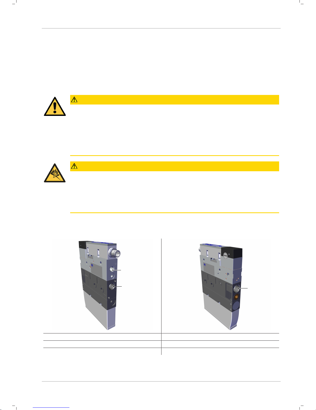
8.3.2Two-Point Mode
The two-point mode is a threshold switch with hysteresis.
When the measurement value increases, the switching point will be active when the switch-on threshold
SPx is reached and remains on until it falls below the reset threshold rPx. The following must always apply
for switching thresholds and reset thresholds: |SPx| > |rPx|. The hysteresis is therefore defined by the difference |SPx – rPx|.
Functions of the Vacuum Switch
EN-US · 30.30.01.01602 · 01 · 10/18 33 / 58
Pressure p
[mbar]
Time t
Switching point SP
Reset point rP
Output NO
Output NC
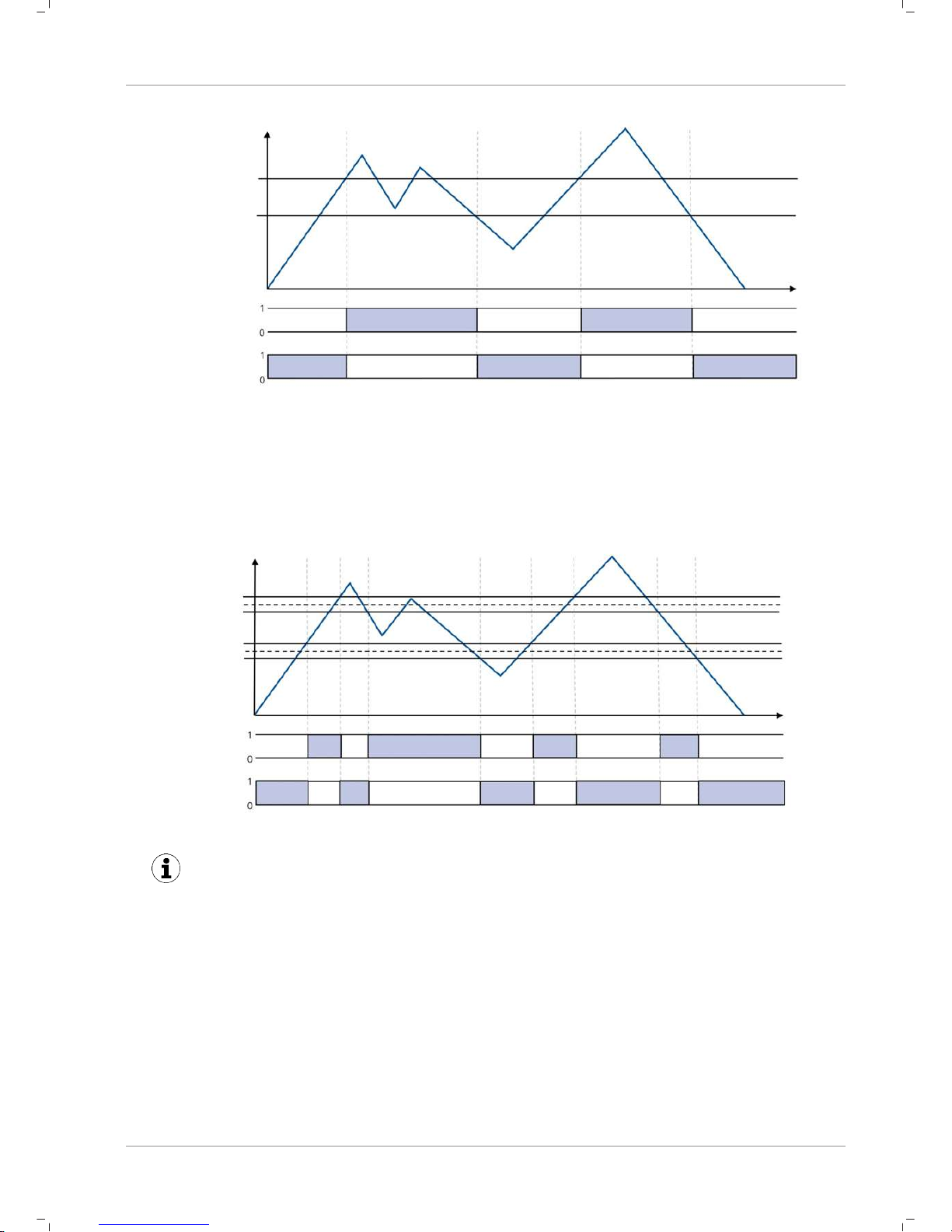
8.3.3Window Mode
In window mode, the switching point is active when the measurement value is between the upper window point FHx and the lower window point FLx. Outside this window, the switching point is inactive. If
necessary, a common switching hysteresis Hyx can be set, which symmetrically applies to both window
points. For the parameters of the upper window point FHx, lower window point FLx and hysteresis Hyx,
the following must always apply: |FHx| > |FLx| + Hyx
Pressure p
[mbar]
Switching point FH
Switching point FL
Output NO
Output NC
Time t
Hysteresis
Hysteresis
}
}
When switching from two-point mode to window mode, the current switching points SPx and
rPx are interpreted as window points FHx and FLx. They are the same internal parameters (also
see the data dictionary). If the resulting set of parameters are not valid in the new mode (e.g.
hysteresis too big in window mode), it is not possible to switch the mode because the difference must be at least 30mbar.
8.3.4Condition Monitoring Mode (Leakage Measurement)
The condition monitoring switching point mode is used to monitor the quality of a vacuum suction system. In this case, the vacuum switch can measure the vacuum leakage in millibars per second between
two drainage cycles. The switching point is then activated when a leakage exceeds its maximum permissible setting, which can be configured.

Functions of the Vacuum Switch
34 / 58 EN-US · 30.30.01.01602 · 01 · 10/18
The detection of an external suction cycle is carried out using the adjustable limit values SPx and rPx that
indicate the limits for picking up and depositing a workpiece. The threshold for the maximum permissible
leakage is set using the parameter L-x in millibars per second. The following diagram shows the case of a
typical suction cycle where the system indicates a leakage and the vacuum generator drains many times:
Pressure p
[mbar]
Switching point SP
Reset point rP
Output
Suction cycle
begins
New
suction cycle
Suction cycle
ends
Time t
Peak recognition activates
leakage measurement
Low
leakage
Low
leakage
High
leakage
Another application for Condition monitoring mode occurs if the regulation threshold of the vacuum system is never achieved and the vacuum generator permanently sucks. In this case, if the end vacuum is
20mbar lower than the start vacuum, the switching point will also be activated.
For a very tight vacuum system where the second case shown always occurs in normal operation and indicates no error, Condition monitoring mode is not suitable.
8.3.5Diagnostics Mode
Diagnostics mode monitors the internal warnings and error messages of the switch. When an error message (error code in display or ISDU 130) or warning (CM bit in ISDI 146) appears, the switching point is activated.
Diagnostics mode also includes the functions of Condition monitoring mode. That means the switching
point is also activated when the leakage measurement results in a warning.
8.4Teach-in for Switching Points
A teach-in function is available to make it easier to set the limit values. This only affects one switching
point on one occasion and changes nothing on the selected switching point mode or switching point
logic.
ü To cancel a teach-in process, the required switching point must first be selected. This is done via IO-
Link, via ISDU 58 or in the menu item "tCX" in the basic menu.
4 In the menu, the teach-in starts immediately when the button is pressed; if it is done via IO-link,
the appropriate system command has to be written via ISDU 2 first.
ð The switch-on threshold SPX or FHx is set for teach-in in such a way that it is 20% below the actual
required measurement value. The reset threshold for vacuum values is set at 50mbar below the
switch-on threshold. The associated hysteresis for window mode is set at 10mbar for vacuum values.
ð After a successful teach-in process, an automatic display cycle of the newly set values appears in the
display.

Functions of the Vacuum Switch
EN-US · 30.30.01.01602 · 01 · 10/18 35 / 58
8.5Additional Switching Point Settings
8.5.1Switch-on and Switch-off Delay
For each switching point and each associated limit value, a delay time can be set, with the exception of
condition monitoring mode. Here, this parameter can only be defined for the switching point SP1. In Condition monitoring mode, the parameters dSx and drx are also not shown on the display.
Due to the switch-on and switch-off delay, short-term fluctuations of the measurement signal can be hidden. In this case, the switch delay dSx is based on a situation in which the measurement value increases
(from the absolute value). Accordingly, the reset delay drx is based on a decreasing measurement value.
The following diagram shows the option to set the delay times using two-point mode:
Pressure p
[mbar]
Switching point SP
Reset point rP
Output NO
Output NC
Time t
Legend:
Switch-on delay (ds)
Reset delay (dr)
8.5.2Transistor Function
The electrical characteristic of the switching outputs can be switched between PNP switching ("plus
switching" or also "24V switching") and NPN switching ("zero switching" or also "GND switching"). Both
switching outputs can always be set together, which does not affect the IO-Link operation.
The transistor function is set in the EF menu under the parameter P-n.
8.6Display Screen
8.6.1Vacuum Unit
The physical unit that is used to display the measured values as well as the limit valuesand hystereses on
the display can be set via the EF menu under the menu item uni or via IO-Link:
Unit Display code, setting parame-
ters
Display unit
Bar
bAr
mbar
Pascal
kPA
kPa
Inch Mercury
iXg
inHg
Pound-force per square inch
P5i
Psi
The selection of the vacuum unit affects only the display, it has no effect on the display of the values via
IO-Link. These are always measured in mbar, see (> See ch. data dictionary).

Functions of the Vacuum Switch
36 / 58 EN-US · 30.30.01.01602 · 01 · 10/18
8.6.2Display Alignment
The display alignment can be rotated by 180 degrees using the parameter di5 to adapt to the installation position of the ejector.
When rotated, the decimal point on the far right is no longer displayed and is therefore missing from the
display of the counter statuses and serial numbers.
8.6.3ECO Mode
The ejector offers the option to switch off the display or to dim the display to save energy.
ECO mode can be activated and deactivated in the EF menu under the menu item Eco or via the IO-Link.
• ECO mode (ECO mode "on"), the display is switched off 1 minute after the last button is pressed.
• ECO mode "Lo": 1 minute after the last button is pressed, the numerical display will reduce to 50%
of its normal brightness.
The display is reactivated by pressing any button or by an error message.
If you activate ECO mode using IO-Link, the display will immediately enter energy-saving
mode.
8.7Access Rights
8.7.1PIN Code for Write Protection
A PIN code can be used to prevent the parameters from being changed using the operating menu.
A PIN is recommended because carrying out parameterization while the device is in operation
can change the status of signal inputs and outputs.
The PIN code is entered in the EF menu under the menu item P1N or via IO-Link.
The current settings are still displayed in a locked state.
The PIN is set to 000 on delivery, meaning access to the parameters is not locked. To activate the write
protection, a PIN code between 001 and 999 must be entered via the menu or IO-Link.
If write protection is activated with a customer-specific PIN, the desired parameters are changed within
one minute of the correct code being entered. If no changes are made within one minute, write protection is automatically reactivated. A PIN of 000 must be reset to permanently deactivate the lock.
Full access to the device is still possible via IO-Link even if a PIN is enabled. The current PIN can also be
read out and changed/deleted (PIN = 000) via IO-Link.
8.7.2IO-Link Device Access Locks
In IO-Link mode, the "Device access locks" default parameter is available to prevent changes to parameter
values using the user menu or IO-Link. You can also prevent the use of the Data storage mechanism described in IO-Link Standard V1.1.
Bit Meaning
0 Parameter write access locked
(Parameters cannot be changed via IO-Link)
1 Data storage locked
(Data storage mechanism is not triggered)
2 Local parametrization locked
(Parameters cannot be changed via the user menu)
Coding for the device access locks

Functions of the Vacuum Switch
EN-US · 30.30.01.01602 · 01 · 10/18 37 / 58
A menu lock using the Device access locks parameter has a higher priority than the menu PIN. In other
words, this lock cannot be bypassed by entering a PIN and remains in SIO mode.
It can only be canceled via IO-Link, not via the ejector or the vacuum switch itself.
8.8Device Identification
The IO-Link protocol provides a range of identification data for compliant devices that can be used to
uniquely identify a device. This product contains even more advanced identification parameters.
The parameters are ASCII character strings that adapt their length to the relevant content.
The following parameters can be queried:
• Manufacturer's name and website
• Product, series and exact type name
• Part number and development status
• Serial number and date code
• Version status of the hardware and firmware
8.9User-Specific Localization
The following parameters are available for each vacuum switch when saving user-specific information:
• Identification of the installation location
• Identification of the storage location
• Equipment labeling from the circuit diagram
• Installation date
• Geo-location
• Web link to the relevant IODD
The parameters are ASCII character strings with the maximum length given in the data dictionary. They
can also be used for other purposes if necessary.
8.10System Monitoring and Diagnostics
8.10.1Minimum and Maximum Values
The maximum and minimum vacuum and operating voltage values that were measured since the last
switch-on are logged by the switch and can be queried.
The maximum and minimum values can be reset via IO-Link during operation using the appropriate system commands.
For the vacuum, it is possible to query the values using the INF menu via the parameters X1 and Lo. The
values are reset using the parameter rxL.
8.10.2Counters
The vacuum switch has two non-erasable counters cc1 and cc2 as well as two erasable counters ct1
and ct2 in the INF menu.
These counters count the positive switching ramps of the switching points 1 and 2:
Designation Display code or param-
eter
Description
Counter 1
cc1
Counter for positive switching ramps SP1 (non-erasable)
Counter 2
cc2
Counter for positive switching ramps SP2 (non-erasable)
Counter 3
ct1
Counter for positive switching ramps SP1 (erasable)
Counter 4
ct2
Counter for positive switching ramps SP2 (erasable)

Functions of the Vacuum Switch
38 / 58 EN-US · 30.30.01.01602 · 01 · 10/18
The average switching frequency of the air saving function can be determined using the difference between counters 1 and 2.
The erasable counters ct1 and ct2 can be reset to 0 during operation via IO-Link by using the appropriate
system commands.
In the operating menu, this is possible via the INF menu and the parameter rct.
The storage of the non-erasable counter readings only occurs every 500 steps. That means that when the
operating voltage is switched off, up to 499 steps of the counter are lost.
8.10.3Status Signals
The current status of the ejector, i.e. whether errors or warnings are active, can be queried in various
ways:
• Using the standard "Device status," "Detailed device status" and "Error count" IO-Link parameters
• Using the "Active error code" and "Condition monitoring" parameters
• Using the "Extended device status," which transmits the entire display of the device status with classification of the severity level of errors and warnings.
8.10.4Leakage Measurement
If one of the switching points for the vacuum switch is set to Condition monitoring mode, the actual leakage measured can be read in millibars per second.
8.11System Commands
8.11.1Resetting to Factory Settings
All adjustable parameters for the vacuum switch are reset to factory settings using this function.
WARNING
By activating/deactivating the product, output signals lead to an action in the production process!
Personal injury
4 Avoid possible danger zone.
4 Remain vigilant.
The function is executed in the EF menu under the parameter re5 or via IO-Link:
1. Press the button.
ð When the menu is locked, enter the valid PIN code.
2. Use the or button to select the menu item EF.
3. Confirm using the button.
ð 0u1 appears on the display.
4. Use the button to select the parameter re5.
5. Press the button.
ð YE5 appears on the display.
6. Press the button again.
ð The vacuum switch is reset to the factory settings.
ð The display flashes briefly and then returns to the display mode.

Functions of the Vacuum Switch
EN-US · 30.30.01.01602 · 01 · 10/18 39 / 58
The Reset to factory settings function does not affect:
• Counter statuses
• The zero-point adjustment of the sensor
• The maximum and minimum values of the measurements
8.11.2Calibrating the Vacuum Sensor
As the production conditions for the internally integrated vacuum sensor can vary, we recommend calibrating the sensor once it is installed in the ejector. To calibrate the vacuum sensor, the system's vacuum
circuit must be open to the atmosphere.
The function for zero-point adjustment of the sensor is performed in the basic menu under the parameter
CAL or using IO-Link.
1. Press the button
ð The menu changes to input
2. Press the or button until cal appears in the display
3. Confirm with the button
4. When YE5 appears, press the button to confirm.
ð The vacuum sensor is now calibrated.
A zero offset is only possible in the range of ± 3% around the theoretical zero position.
When the permissible limit is exceeded by ±3%, error code E03 will appear in the display.

Operation
40 / 58 EN-US · 30.30.01.01602 · 01 · 10/18
9Operation
9.1General Preparations
WARNING
Extraction of hazardous media, liquids or bulk material
Personal injury or damage to property!
4 Do not extract harmful media such as dust, oil mists, vapors, aerosols etc.
4 Do not extract aggressive gases or media such as acids, acid fumes, bases, biocides, dis-
infectants or detergents.
4 Do not extract liquids or bulk materials, e.g. granulates.
Always carry out the following tasks before activating the system:
1. Before each use, check that the safety devices are in perfect condition.
2. Check the ejector for visible damage and deal with any problems immediately (or notify your supervisor).
3. Ensure that only authorized personnel are present in the working area of the machine or system and
that no other personnel are put in danger by switching on the machine.
There must be no people in the system danger area while it is in operation.

Troubleshooting
EN-US · 30.30.01.01602 · 01 · 10/18 41 / 58
10Troubleshooting
10.1Help with Malfunctions
Error Cause Measure
Master or peripheral
power supply disturbed
Connection to IO-Link master with
IO-Link class-B port
4 Connection to IO-Link class A port
No output signal Incorrect electrical connection 4 Check electrical connection and PIN
assignment
Transistor function (PNP/NPN) not
appropriate for the application
4 Adjust the transistor function (PNP/
NPN) to the device's electrics
Switching logic inverted 4 Adjust the NO/NC switching point
logic
No IO-Link communication
Incorrect electrical connection 4 Check electrical connection and pin
assignment
Master not correctly configured 4 Check configuration of the master
to see whether the port is set to IOLink
IODD connection does not work 4 Check for the appropriate IODD
Ejector does not respond
No compressed air supply 4 Check the compressed air supply
Vacuum level is not
reached or vacuum is
built up too slowly
Press-in screen is contaminated 4 Replace screen
Silencer is soiled 4 Replace silencer insert
Leakage in hose line 4 Eliminate leakage from hose con-
nections
Leakage at suction cup 4 Eliminate leakage from suction cup
Operating pressure too low 4 Increase operating pressure, ob-
serve maximum limits
Internal diameter of hose line too
small
4 Observe recommendations for hose
diameter
Load cannot be held Vacuum level is too low 4 Increase the control range for the
air saving function
Suction cup too small 4 Select a larger suction cup
No display on the
screen
ECO mode activated 4 Press any button or deactivate ECO
mode
Incorrect electrical connection 4 Check electrical connection and PIN
assignment
Display shows error
code
See "Error codes" table 4 See "Error Codes" table in the fol-
lowing chapter
IO-Link warning message "Leakage too
high" although handling cycle is working
optimally
Limit value L-x (permissible leakage per second) set too low
4 Determine typical leakage values in
a good handling cycle and set as
limit value
Limit values SPx and rPx for leak-
age measurement set too low
4 Set limit values in such a way that
there is a clear differentiation be-
tween the neutral and suction sys-
tem statuses
IO-Link warning message "Leakage too
high" does not appear
although there is high
leakage in the system
Limit value L-x (permissible leakage per second) set too high
4 Determine typical leakage values in
a good handling cycle and set as
limit value

Troubleshooting
42 / 58 EN-US · 30.30.01.01602 · 01 · 10/18
Error Cause Measure
Limit values SPx and rPx for leakage measurement set too high
4 Set limit values in such a way that
there is a clear differentiation between the neutral and suction system statuses
10.2List of Error Numbers
When a known error occurs, this is reported in the form of an error number. In SIO mode, the error messages are displayed periodically in the display with the measured value. On the display, an "E" for error
precedes the error message, followed by the error number.
One exception is error E07 (operating voltage too low): in this case "E07" will be permanently indicated in
the display and the ejector will delay further user entries until the operating voltage has reached the necessary level again.
The following table shows all of the error codes:
Display code Fault Possible cause Measure
E01
Data error Electronic errors – internal data
management – EEPROM, operating voltage was disconnected too
quickly after changing the parameters, saving process was not complete
4 Reset to factory settings,
recording of a valid data set
via IO-Link (with engineering
tool)
E03
CAL error Zero point adjustment of the vac-
uum sensor outside ± 3% FS
CAL was canceled when the measurement value was too high or
too low
4 Vent pneumatic connection
before CAL is carried out
E07
Under voltage US
Supply voltage is too low 4 Check power supply and
power load
E08
Communication canceled
IO-Link communication canceled
without explicit "fallback" from
master
4 Check cabling for the master
E11
Overload/short
circuit OUT1
Power load too high, short circuit 4 Check cabling and power con-
sumption for the connected
consumers
E12
Overload/short
circuit OUT2
Power load too high, short circuit 4 Check cabling and power con-
sumption for the connected
consumers
E17
Over voltageUSSupply voltage is too high 4 Check power supply
E19
Overheating Ambient temperature too high,
output continuous load too high
4 Ensure ventilation/cooling,
check the power consumption
of the connected consumers

Troubleshooting
EN-US · 30.30.01.01602 · 01 · 10/18 43 / 58
Display code Fault Possible cause Measure
E20
Teach-in error
Teach-in was carried out with invalid measured value (FFF/-FF),
teach-in of the leakage mode was
carried out with existing pressure
4 Measurement value must be in
the valid measurement range
FFF
Measurement range
exceeded
Overpressure in the system, e.g.
when blowing off
—
-FF
Overpressure
in vacuum
circuit
Overpressure in the system, e.g.
when blowing off
—
Error codes
The error E01 remains in the display after being shown once. Delete the error by switching off the
power supply. If this error occurs again after the power supply is switched back on, then the device must
be replaced.
10.3Warnings and Error Messages in IO-Link Mode
In IO-Link mode, status information is available in addition to the error messages displayed in SIO mode.
The following section from the data dictionary shows detailed information here.
Any condition monitoring events that occur during the suction cycle cause the system status light to immediately switch from green to yellow. The specific event that caused this switch can be seen in the "Condition monitoring" IO-Link parameter.

Maintenance
44 / 58 EN-US · 30.30.01.01602 · 01 · 10/18
11Maintenance
11.1Safety
Maintenance work may only be carried out by qualified personnel.
WARNING
Risk of injury due to incorrect maintenance or troubleshooting
4 Check the proper functioning of the product, especially the safety features, after every
maintenance or troubleshooting operation.
NOTE
Incorrect maintenance work
Damage to the ejector!
4 Always switch off supply voltage before carrying out any maintenance work.
4 Secure before switching back on.
4 The ejector must only be operated with a silencer and press-in screens.
4 Create atmospheric pressure in the ejector's compressed air circuit before working on the system!
11.2Cleaning the Ejector
1. For cleaning, do not use aggressive cleaning agents such as industrial alcohol, white spirit or thinners. Only use cleaning agents with pH 7–12.
2. Remove dirt on the exterior of the device with a soft cloth and soap suds at a maximum temperature of 60° C. Make sure that the silencer is not soaked in soapy water.
3. Ensure that no moisture can reach the electrical connection or other electrical components.
11.3Replacement of the Device with a Parameterization Server
The IO-Link protocol provides an automated process for transferring data when a device is replaced. For
this Data storage mechanism, the IO-Link master mirrors all setting parameters for the device in a separate non-volatile memory. When a device is swapped for a new one of the same type, the setting parameters for the old device are automatically saved in the new device by the master.
ü The device is operated on a master with IO-Link revision 1.1 or higher.
ü The Data storage feature in the configuration of the IO-Link port is activated.
4 Ensure that the new device is restored to the factory settings before it is connected to the IO-Link
master. If necessary, reset the device to factory settings, e.g. via the operating menu.
ð The device parameters are automatically mirrored in the master when the device is configured using
an IO-Link configuration tool.
ð Changes to the parameters made in the user menu on the device are automatically mirrored in the
master.
Changes to the parameters made by a PLC program using a function module are not automatically mirrored in the master.
4 Manually mirroring data: After changing all the required parameters, execute ISDU write access to
the System command parameter (index 2) with the ParamDownloadStore command (numerical
value 5).

Maintenance
EN-US · 30.30.01.01602 · 01 · 10/18 45 / 58
Use the Parameterization server function of the IO-Link master to ensure that no data is lost
when switching the device.

Warranty
46 / 58 EN-US · 30.30.01.01602 · 01 · 10/18
12Warranty
This system is guaranteed in accordance with our general terms of trade and delivery. The same applies to
spare parts, provided that these are original parts supplied by us.
We are not liable for any damage resulting from the use of non-original spare parts or accessories.
The exclusive use of original spare parts is a prerequisite for the proper functioning of the ejector and for
the validity of the warranty.
Wearing parts are not covered by the warranty.
Opening the ejector will damage the "tested" labels. This voids the warranty.

Spare and Wearing Parts, Accessories
EN-US · 30.30.01.01602 · 01 · 10/18 47 / 58
13Spare and Wearing Parts, Accessories
13.1Spare and Wearing Parts
Maintenance work may only be carried out by qualified personnel.
WARNING
Risk of injury due to incorrect maintenance or troubleshooting
4 Check the proper functioning of the product, especially the safety features, after every
maintenance or troubleshooting operation.
The following list contains the primary spare and wearing parts.
Part no. Designation Legend
10.02.02.03381 Silencer insert W
Legend:
• Wearing part = W
4 When tightening the fastening screws on the silencer module, observe the maximum tightening
torque of 0.5Nm.
13.2Accessories
Part no. Designation Note
10.02.02.00158 Connection cable M12, 5-pin, to 5-pin M12 connector, 1m
21.04.05.00080 Connection cable M12, 5-pin, with open end, 5m

Decommissioning and recycling
48 / 58 EN-US · 30.30.01.01602 · 01 · 10/18
14Decommissioning and recycling
14.1Disposing of the Ejector
1. Dispose of the product properly after replacement or decommissioning.
2. Observe the country-specific guidelines and legal obligations for waste prevention and disposal.
14.2Materials Used
Component Material
Housing PA6-GF, PC-ABS, AL
Inner components Aluminum alloy, anodized aluminum alloy, brass, galvanized steel, stainless-
steel, PU, POM
Silencer insert Porous PE
Screws Galvanized steel
Sealing Nitrile rubber (NBR)
Lubrication Silicone-free
Main body: Stainless steel (1.4435 BN II)
Sealing: VMQ – 65 Shore (FDA 177.2600-21)

Appendix
EN-US · 30.30.01.01602 · 01 · 10/18 49 / 58
15Appendix
See also
2 SCPi_CE_30.30.01.01667-00.pdf [}50]
2 SCPi_Data Dictionary_01.pdf [}51]


IO-Link Data Dictionary SMP FS RP
21.10.01.00115/00 13.03.2018
J. Schmalz GmbH
Aacher Straße 29, D 72293 Glatten
Tel.: +49(0)7443/2403-0
Fax: +49(0)7443/2403-259
info@schmalz.de
7…0 Most significant 8 bits of sensor measurement value (mbar)
7…2 Least significant 6 bits of sensor measurement value (mbar)
1 Boolean ro Logic state of switch point 2
0 Boolean ro Logic state of switch point 1
Process Data Input
SIO-Mode
Bits
Process Data Output
IO-Link Bitrate
Minimum Cycle Time
PD In Byte 0
Vacuum in mbar, MSB
Data Type
ro
38.4 kBit/sec (COM2)
Switching Point 1
Access
Process Data Input
IO-Link Implementation
Process Data
Remark
Switching Point 2
Name
PD In Byte 1
IO-Link Revision
IO-Link Profile
Smart Sensor Profile with 2 Binary Data Channels, 1 Process Data Variable, Teach-In and Diagnosis
234 (0x00EA)
100244 (0x018794)
Yes
1.1 (compatible with 1.0)
Device ID
Vendor ID
2.3 ms
2 bytes
None
Special Values
VSi V: 10000 = Overflow, 16383 = Underflow (pressure)
Vacuum in mbar, LSB
VSi V: 14-bit unsigned integer
J. Schmalz GmbH
1 of 6 VSi Data Dictionary

IO-Link Data Dictionary SMP FS RP
21.10.01.00115/00 13.03.2018
J. Schmalz GmbH
Aacher Straße 29, D 72293 Glatten
Tel.: +49(0)7443/2403-0
Fax: +49(0)7443/2403-259
info@schmalz.de
Subindex
dec hex dec
16 0x0010 0 1...32 bytes ro J. Schmalz GmbH Manufacturer designation
17 0x0011 0 1...32 bytes ro www.schmalz.com Internet address
18 0x0012 0 1...32 bytes ro SCP 25 NO FS RP General product name
19 0x0013 0 1...32 bytes ro SCP 25 NO FS RP Product variant name
20 0x0014 0 1...32 bytes ro SCP 25 NO FS RP Order-code
21 0x0015 0 Snr 9 bytes ro 000000001 Serial number
22 0x0016 0 2 bytes ro 00 Hardware revison
23 0x0017 0 SoC 4 bytes ro 1.11 Firmware revision
240 0x00F0 0 20 bytes ro Unique device identification number
241 0x00F1 0 11 bytes ro Type code of device features (see IODD)
250 0x00FA 0 Art 14 bytes ro 10.02.02.* Order-number
251 0x00FB 0 2 bytes ro 00 Article revision
252 0x00FC 0 3 bytes ro Date code of production (month, year)
254 0x00FE 0 1...64 bytes ro SCP 25 NO FS RP Detailed type description of the device
24 0x0018 0 1...32 bytes rw *** User string to store location or tooling information
242 0x00F2 0 1…64 bytes rw *** User string to store identification name from schematic
246 0x00F6 0 1…64 bytes rw *** User string to store geolocation from handheld device
247 0x00F7 0 1…64 bytes rw *** User string to store web link to IODD file
249 0x00F9 0 1…32 bytes rw *** User string to store storage location
253 0x00FD 0 1…16 bytes rw *** User string to store date of installation
Value Range
Vendor Text
Display
Appearance
ISDU Parameters
Identification
Device Features
Device Management
Installation Date
Application Specific Tag
Remark
Access
Parameter
Hardware Revision
Product Text
Unique ID
Vendor Name
Product ID
Size
Firmware Revision
Production Date
ISDU Index
Product Name
Article Number
Article Revision
Serial Number
Detailed Product Text
Geolocation
Storage Location
Equipment Identification
Device Localization
IODD Web Link
Default Value
J. Schmalz GmbH
2 of 6 VSi Data Dictionary

IO-Link Data Dictionary SMP FS RP
21.10.01.00115/00 13.03.2018
J. Schmalz GmbH
Aacher Straße 29, D 72293 Glatten
Tel.: +49(0)7443/2403-0
Fax: +49(0)7443/2403-259
info@schmalz.de
2 0x0002 0 1 byte
5, 65, 130, 165,
66, 167, 168, 169
wo
0x05 (dec 5): Force upload of parameter data into the master
0x41 (dec 65): Execute single-value teach for currently selected SPx
0x82 (dec 130): Restore device parameters to factory defaults
0xA5 (dec 165): Calibrate sensor
0xA7 (dec 167): Reset erasable counters ct1 and ct2
0xA8 (dec 168): Reset voltage HI/LO
0xA9 (dec 169): Reset sensor HI/LO
58 0x003A 0 1 byte 1, 2 rw Select switch point 1 or 2 for teaching
59 0x003B 0 1 byte ro
Result of last teach-in command:
0x00 = Channel changed
0x07 = Teach-in failed
0x11 = Teach-in successful
12 0x000C 0 2 bytes 0 - 7 rw 0
Bit 0: Parameter access lock (lock ISDU-write access)
Bit 1: Data storage lock
Bit 2: Local parameterization lock (lock menu editing)
77 0x004D 0 Pin 2 bytes 0 - 999 rw 0
0 = Menu editing unlocked
>0 = Menu editing locked with pin-code
73 0x0049 0 P-n 1 byte 0 - 1 rw 0
0 = PNP
1 = NPN
74 0x004A 0 uni 1 byte 0 - 3 rw 0
0 = mbar
1 = kPa
2 = inHg
3 = psi
76 0x004C 0 Eco 1 byte 0 - 2 rw 0
0 = off
1 = on (full eco mode with display switching off completely)
2 = Lo (medium eco mode with display dimmed to 50%)
79 0x004F 0 dIS 1 byte 0 - 1 rw 0
0 = Standard
1 = Rotated
Device Settings
Teach-In Status
Signal Type
Eco-Mode
Initial Settings
Display Rotation
Display Unit
Menu PIN code
Device Access Locks
Teach-In Channel
Parameter
System Command
Commands
Access Control
J. Schmalz GmbH
3 of 6 VSi Data Dictionary

IO-Link Data Dictionary SMP FS RP
21.10.01.00115/00 13.03.2018
J. Schmalz GmbH
Aacher Straße 29, D 72293 Glatten
Tel.: +49(0)7443/2403-0
Fax: +49(0)7443/2403-259
info@schmalz.de
60 0x003C 1 SP1/FH1 2 bytes rw Unit mbar
60 0x003C 2 rP1/FL1 2 bytes rw Unit mbar
61 0x003D 1 Ou1 1 byte 0 - 1 rw 0
0 = NO
1 = NC
61 0x003D 2 Ou1 1 byte 2, 3, 128, 129 rw 3
2 = Window Mode
3 = Two-Point Mode
128 = Condition Monitoring (not for VSi P10)
129 = Diagnostic Mode
61 0x003D 3 Hy1 2 bytes rw Unit mbar
75 0x004B 1 dS1 2 bytes 0 - 999 rw Unit ms
75 0x004B 2 dr1 2 bytes 0 - 999 rw Unit ms
62 0x003E 1 SP2/FH2 2 bytes rw Unit mbar
62 0x003E 2 rP2/FL2 2 bytes rw Unit mbar
63 0x003F 1 Ou2 1 byte 0 - 1 rw 0
0 = NO
1 = NC
63 0x003F 2 Ou2 1 byte 2, 3, 128, 129 rw 3
2 = Window Mode
3 = Two-Point Mode
128 = Condition Monitoring (not for VSi P10)
129 = Diagnostic Mode
63 0x003F 3 Hy2 2 bytes rw Unit mbar
80 0x0050 1 dS2 2 bytes 0 - 999 rw Unit ms
80 0x0050 2 dr2 2 bytes 0 - 999 rw Unit ms
108 0x006C 0 -L- 2 bytes 0 - 999 rw Unit mbar/sec
Process Settings
Switch Point 1 - Switch-on delay
Switch Point 2 - Upper Threshold
Switch Point 2 - Lower Threshold
Switch Point 2 - Mode
Switch Point 1 - Upper Threshold
Switch Point 1 - Lower Threshold
Switch Point 1 - Logic
Switch Point 1 - Mode
Switch Point 2 - Logic
Switch Point 1 - Window Hysteresis
Switch Point 2 - Switch-on delay
Permissible Leakage Rate
Condition Monitoring [CM]
Switch Point 2 - Switch-off delay
Switch Point 1 - Switch-off delay
Switch Point 2 - Window Hysteresis
Switch Point 1
Switch Point 2
J. Schmalz GmbH
4 of 6 VSi Data Dictionary

IO-Link Data Dictionary SMP FS RP
21.10.01.00115/00 13.03.2018
J. Schmalz GmbH
Aacher Straße 29, D 72293 Glatten
Tel.: +49(0)7443/2403-0
Fax: +49(0)7443/2403-259
info@schmalz.de
40 0x0028 0 2 bytes ro Copy of currently active process data input
64 0x0040 1 2 bytes ro Actual sensor value
64 0x0040 2 2 bytes ro Lowest measured sensor value since power-up
64 0x0040 3 2 bytes ro Highest measured sensor value since power-up
66 0x0042 1 2 bytes ro Supply voltage as measured by the device (unit: 0.1 Volt)
66 0x0042 2 2 bytes ro Lowest measured supply voltage since power-up
66 0x0042 3 2 bytes ro Highest measured supply voltage since power-up
564 0x0234 0 1 byte ro
0x00 = SIO mode
0x10 = IO-Link revision 1.0 (set by master)
0x11 = IO-Link revision 1.1 (set by master)
140 0x008C 0 cc1 4 bytes ro Switch-on counter for switch point 1 (non-erasable)
141 0x008D 0 cc2 4 bytes ro Switch-on counter for switch point 2 (non-erasable)
143 0x008F 0 ct1 4 bytes ro Switch-on counter for switch point 1 (erasable)
144 0x0090 0 ct2 4 bytes ro Switch-on counter for switch point 2 (erasable)
32 0x0020 0 2 bytes ro Number of errors since last power-up
36 0x0024 0 1 byte ro
0 = Device is operating properly
1 = Maintenance required
2 = Out of specification
3 = Functional check
4 = Failure
37 0x0025 1-15 15 x 3 bytes ro
Information about currently pending events
Fixed-length array format according to IO-Link specification V1.1
130 0x0082 0 1 byte ro
0 = No error
1-99 = Error code displayed by the device
138 0x008A 1 1 byte ro Type code of active device status (see below)
138 0x008A 2 2 bytes ro ID code of active device status (see below)
146 0x0092 0 Condition Monitoring 1 byte ro
Bit 2: Leakage rate above limit -L- (not for VSi P10)
Bit 5: Primary voltage US outside of optimal range
160 0x00A0 0 Actual Leakage Rate 2 bytes ro Leakage rate, unit mbar/sec (not for VSi P10)
Supply Voltage
Error Count
Condition Monitoring [CM]
Sensor Value
Sensor Value HI
Monitoring
Process Data In Copy
Observation
Counter cc2
Diagnosis
Device Status
Supply Voltage LO
Sensor Value LO
Detailed Device Status
Supply Voltage HI
Counter ct1
Counter cc1
IO-Link Device Status
Communication Mode
Active Error Code
Counter ct2
Extended Device Status - Type
Extended Device Status - ID
Process Data
Communication Mode
Counters
J. Schmalz GmbH
5 of 6 VSi Data Dictionary

IO-Link Data Dictionary SMP FS RP
21.10.01.00115/00 13.03.2018
J. Schmalz GmbH
Aacher Straße 29, D 72293 Glatten
Tel.: +49(0)7443/2403-0
Fax: +49(0)7443/2403-259
info@schmalz.de
ID
0x0000
0x0002
0x0007
0x000A
0x0017
0x000C
0x000D
0x0015
0x0010
0x0011
0x0016
0x0000
Type Color
Type Text
Warning upper
Critical condition lower
Orange
Parameter ISDU 138 - Extended Device Status
0x10
Type
Status Text
Green
0x21
Yellow
Warning lower
Leakage rate above limit
0x22
Yellow
Primary supply voltage US outside of operating range
Yellow
Warning upper
Teach-In failed
Everything OK
Everything OK
0x41
0x81
Red
Defect lower
Internal parameter data invalid
0x22
Yellow
Warning upper
Sensor calibration failed
0x22
0x42
Orange
Critical condition upper
IO-Link communication interruption
Orange
Critical condition upper
Primary supply voltage US too low
0x41
Orange
Critical condition lower
Overload OUT1
0x41
Orange
Critical condition lower
Overload OUT2
0x42
Orange
Critical condition upper
Primary supply voltage US too high
Overtemperature
0x42
J. Schmalz GmbH
6 of 6 VSi Data Dictionary

Notes
EN-US · 30.30.01.01602 · 01 · 10/18 57 / 58
16Notes

© J.SchmalzGmbH · EN-US · 30.30.01.01602 · 01 · 10/18 · Subject to technical changes without notice
 Loading...